CN102064589B - Charging device for valve-regulated lead-acid battery - Google Patents
Charging device for valve-regulated lead-acid batteryDownload PDFInfo
- Publication number
- CN102064589B CN102064589BCN 201110039359CN201110039359ACN102064589BCN 102064589 BCN102064589 BCN 102064589BCN 201110039359CN201110039359CN 201110039359CN 201110039359 ACN201110039359 ACN 201110039359ACN 102064589 BCN102064589 BCN 102064589B
- Authority
- CN
- China
- Prior art keywords
- charging
- voltage
- storage battery
- charge
- current
- Prior art date
- Legal status (The legal status is an assumption and is not a legal conclusion. Google has not performed a legal analysis and makes no representation as to the accuracy of the status listed.)
- Expired - Fee Related
Links
Images


Landscapes
- Secondary Cells (AREA)
- Charge And Discharge Circuits For Batteries Or The Like (AREA)
Abstract
Description
Translated fromChinese技术领域technical field
本发明涉及蓄电池充电的技术领域,具体是一种阀控式铅酸蓄电池的充电装置。The invention relates to the technical field of battery charging, in particular to a charging device for a valve-regulated lead-acid battery.
背景技术Background technique
铅酸蓄电池是由多个单格电池串联组成。阀控式铅酸蓄电池寿命提前终止的两个最主要的因素是正板栅的软化腐蚀和电解液过度失水。对于免维护型阀控式铅酸蓄电池失水10%容量减少20%,失水25%寿命即终止。因此,该类蓄电池如何在充电过程中减少失水量成为延长阀控式铅酸蓄电池寿命的关键。A lead-acid battery is composed of multiple cells connected in series. The two most important factors for the premature end of life of valve-regulated lead-acid batteries are softening corrosion of the positive grid and excessive loss of water from the electrolyte. For the maintenance-free valve-regulated lead-acid battery, the capacity will be reduced by 20% if the water loss is 10%, and the life will be terminated if the water loss is 25%. Therefore, how to reduce the water loss during the charging process of this type of battery has become the key to prolonging the life of the valve-regulated lead-acid battery.
阀控式铅酸蓄电池失水的主要形式是在充电电压上升到单个栅格电压2.35V,正极发生水分解副反应析出氧气,充电电压上升到单格2.42V负极析出氢气,也就是达到充满电电压的70%从正极开始析出氧气,达到充满电压的90%开始析出氢气,正常情况下充电由于正负极之间氧通道的存在,氧气会被负极活化物反应吸收而不会形成失水,即使到达充满电的电压数值,铅酸蓄电池栅格内部温度不高时,氧气和氢气所形成的压力也不足以顶破并冲出阀帽而形成大量失水(只有轻微失水)。但是,在室温(25℃)以下的春秋冬季节,温度偏低,有时甚至达到-20℃以下充电(铅酸蓄电池的电解液的冰点适于达到-25℃以下,有的可达-40℃),此时由于正负极液体相对粘稠,化学反应速度和离子移动速度比较缓慢,外在表现为内阻值增加,充电接电能力大大下降,正极降为正常室温的70%以下,负极更是达到40%以下,如果在初始充电阶段不加预热地仍然使用大电流充电,则会导致电化学极化电压的急速上升和电池综合阻抗的快速增加,同时充电产生的热量(Q=I2Rt)快速增多、各栅格两端的电压非正常地在初始充电阶段快速上升。The main form of dehydration of valve-regulated lead-acid batteries is that when the charging voltage rises to a single grid voltage of 2.35V, the side reaction of water decomposition occurs on the positive electrode to precipitate oxygen, and the charging voltage rises to a single grid voltage of 2.42V to precipitate hydrogen gas on the negative electrode, that is, it reaches full charge. Oxygen will be precipitated from the positive electrode at 70% of the voltage, and hydrogen will be precipitated at 90% of the full voltage. Under normal charging, due to the existence of oxygen channels between the positive and negative electrodes, oxygen will be absorbed by the negative electrode activator without dehydration. Even if the fully charged voltage value is reached, when the internal temperature of the lead-acid battery grid is not high, the pressure formed by oxygen and hydrogen is not enough to burst and rush out of the valve cap to cause a large amount of dehydration (only a slight dehydration). However, in the spring, autumn and winter seasons below room temperature (25°C), the temperature is low, sometimes even below -20°C for charging (the freezing point of the electrolyte of lead-acid batteries is suitable for below -25°C, and some can reach -40°C ), at this time, because the positive and negative liquids are relatively viscous, the chemical reaction speed and ion movement speed are relatively slow, the external performance is that the internal resistance value increases, the charging and connecting ability is greatly reduced, the positive electrode drops below 70% of the normal room temperature, and the negative electrode It is even lower than 40%. If high current charging is still used without preheating in the initial charging stage, it will lead to a rapid increase in the electrochemical polarization voltage and a rapid increase in the overall impedance of the battery. At the same time, the heat generated by charging (Q= I2 Rt) increases rapidly, and the voltage across each grid rises abnormally and rapidly during the initial charging stage.
图1为室温(即25℃)条件下的阀控式铅酸蓄电池在充电时的蓄电池电压曲线。其中,在恒流充电阶段(即上述曲线的a-b段),蓄电池电压上升的速度较慢,蓄电池接受充电也主要在这个阶段,一般可接受整个充电量的70%-85%。上述恒流充电阶段结束后,依次采用恒压充电(即上述曲线的b-f段)和浮充充电(即上述曲线的g-h段)。Figure 1 is the battery voltage curve of the valve-regulated lead-acid battery at room temperature (ie 25°C) during charging. Among them, in the constant current charging stage (that is, the a-b section of the above curve), the battery voltage rises slowly, and the battery is mainly charged at this stage, and generally 70%-85% of the entire charging capacity can be accepted. After the above constant current charging stage is over, constant voltage charging (that is, the b-f section of the above curve) and floating charge (that is, the g-h section of the above curve) are adopted in sequence.
电解液内阻随温度的降低而增大,随温度的升高而减小。以25℃为基准,每降低10℃,则内阻增大12%~15%;温度趋于越低,内阻增大的幅度加大。这主要是由于硫酸溶液的比电阻与粘度增大的缘故。The internal resistance of the electrolyte increases with decreasing temperature and decreases with increasing temperature. Taking 25°C as the benchmark, the internal resistance will increase by 12% to 15% for every 10°C decrease; the lower the temperature tends to be, the larger the increase in internal resistance will be. This is mainly due to the increase in the specific resistance and viscosity of the sulfuric acid solution.
若在低温条件以下充电,由于没有预热,将导致电池电压上升速度较快,从而使电池电压从所述曲线上的a点到达析气电压b点的时间被大幅缩短,并使得整个充电过程的安时数少于电池标称放电容量所需的安时数(电池容量的110%-130%),即在低温条件下,采用图1的先恒流、后恒压(即通常在恒压充电至析气点后进行恒压充电,如果始终恒流充电将导致大量失水)的充电方法,将使得电池充不饱;同时,由于初期发热大,导致充电后期栅格内部压力较大,氧气和氢气顶破并冲出阀帽形成大量失水,使用恒流定时充电方式时失水量更大。If charging under low temperature conditions, because there is no preheating, the battery voltage will rise faster, so that the time for the battery voltage to reach the gassing voltage point b from point a on the curve is greatly shortened, and the entire charging process The number of ampere-hours is less than the number of ampere-hours required for the battery's nominal discharge capacity (110%-130% of the battery capacity), that is, under low temperature conditions, use the constant current first and then constant voltage in Figure 1 (that is, usually at constant Constant voltage charging after charging to the gassing point, if constant current charging will cause a large amount of water loss), the battery will not be fully charged; at the same time, due to the high initial heat generation, the internal pressure of the grid will be relatively high in the later stage of charging , Oxygen and hydrogen burst and rush out of the valve cap to form a large amount of water loss, and the amount of water loss is even greater when using the constant current timing charging method.
如何解决在低温下充电失水的问题,是本领域的技术难题。How to solve the problem of dehydration during charging at low temperature is a technical problem in this field.
发明内容Contents of the invention
本发明要解决的技术问题是提供一种适于避免低温下充电失水的阀控式铅酸蓄电池的充电装置。The technical problem to be solved by the present invention is to provide a charging device for a valve-regulated lead-acid battery suitable for avoiding water loss during charging at low temperature.
为解决上述技术问题,本发明提供了一种阀控式铅酸蓄电池的充电装置,其包括:整流供电电路;脉冲功率放大及变压电路,与该整流供电电路的电源输出端相连,用于向蓄电池提供充电电源;充电取样回路,设于所述脉冲功率放大及变压电路的输出端和蓄电池之间,用于检测充电电流和电压;充电控制电路,用于控制所述脉冲功率放大及变压电路的输出电压,并通过所述充电取样回路测得的充电电流和电压计算出蓄电池的实时内阻Rt。In order to solve the above-mentioned technical problems, the present invention provides a charging device for a valve-regulated lead-acid battery, which includes: a rectification power supply circuit; Provide charging power to the storage battery; charging sampling circuit, set between the output terminal of the pulse power amplification and voltage transformation circuit and the storage battery, for detecting charging current and voltage; charging control circuit, for controlling the pulse power amplification and Transform the output voltage of the circuit, and calculate the real-time internal resistance Rt of the storage battery through the charging current and voltage measured by the charging sampling circuit.
进一步,若蓄电池中的电解液在温度为25℃时蓄电池的内阻为RT,当测得蓄电池的实时内阻Rt≤RT,即所述电解液的温度不低于25℃时,对该蓄电池进行恒流充电,且充电电流的大小为0.1C(C为蓄电池标称容量);直至该蓄电池的电压到达该蓄电池的析气电压值时,进行恒压充电;当该蓄电池的电压到达额定饱和电压时,经浮充充电一段时间后结束充电;若在浮充充电过程中,测得所述电解液的温度升高时,立即停止浮充充电。Further, if the internal resistance of the battery is RT when the temperature of the electrolyte in the battery is 25°C, when the real-time internal resistance Rt ≤ RT of the battery is measured, that is, when the temperature of the electrolyte is not lower than 25°C, Carry out constant current charging to the storage battery, and the size of the charging current is 0.1C (C is the nominal capacity of the storage battery); carry out constant voltage charging until the voltage of the storage battery reaches the gassing voltage value of the storage battery; when the voltage of the storage battery When the rated saturation voltage is reached, the float charge will be finished after a period of time; if the temperature of the electrolyte is measured to rise during the float charge, the float charge will be stopped immediately.
进一步,当测得Rt>RT,即所述电解液的温度低于25℃时,先以小于0.1C的充电电流对该蓄电池充电一个或多个时段;其中,在以小于0.1C的充电电流对该蓄电池充电多个时段时,各时段的充电电流先后依次增大;直至Rt≤RT,即所述电解液的温度不低于25℃时,采用0.1C的充电电流进行恒流充电,直至该蓄电池的电压到达该蓄电池的析气电压值时,进行恒压充电;当该蓄电池的电压到达额定饱和电压时,经浮充充电一段时间后结束充电。Further, when it is measured that Rt >RT , that is, when the temperature of the electrolyte is lower than 25°C, first charge the battery with a charging current of less than 0.1C for one or more periods of time; wherein, at a charging current of less than 0.1C When the charging current charges the storage battery for multiple periods, the charging current of each period increases successively; until Rt ≤ RT , that is, when the temperature of the electrolyte is not lower than 25°C, the charging current of 0.1C is used for constant When the voltage of the battery reaches the gassing voltage value of the battery, constant voltage charging is carried out; when the voltage of the battery reaches the rated saturation voltage, the charging is completed after a period of float charging.
进一步,在以小于0.1C的充电电流对该蓄电池充电多个时段时,各时段的长度一致。Further, when the storage battery is charged for multiple time periods with a charging current less than 0.1C, the lengths of each time period are consistent.
进一步,在同一时段内的充电电流的大小不变,以方便检测蓄电池内阻大小。Further, the magnitude of the charging current in the same period of time remains unchanged, so as to facilitate the detection of the internal resistance of the storage battery.
进一步,当测得所述Rt大于所述电解液的温度低于10℃时的内阻时,以小于0.1C的充电电流对该蓄电池充电多个时段,且各时段的充电电流先后依次增大,以逐步采用固定大小的直流电对蓄电池充电并预热电解液,使电解液的温度逐渐到达适于充电的最佳温度。各时段的充电电流先后依次增大,可防止温度过快上升带来的失水问题。Further, when it is measured that the Rt is greater than the internal resistance when the temperature of the electrolyte is lower than 10°C, the battery is charged with a charging current of less than 0.1C for multiple periods, and the charging current of each period increases successively. Large, to gradually use a fixed size of direct current to charge the battery and preheat the electrolyte, so that the temperature of the electrolyte gradually reaches the optimum temperature for charging. The charging current of each time period increases successively, which can prevent the problem of dehydration caused by excessive temperature rise.
进一步,所述脉冲功率放大及变压电路包括:开关管VMOS和变压器T;开关管VMOS的电流输入端和电流输出端分别与整流电路的输出端和变压器T的初级线圈连接,开关管VMOS的控制端与充电控制电路的控制信号输出端连接;变压器T的次级与作为输出端与充电取样回路的输入端连接,充电取样回路的电源输出端与蓄电池相连;充电控制电路通过控制所述控制信号输出端的PWM脉冲信号的脉宽,来控制充电电压。Further, the pulse power amplification and voltage transformation circuit includes: a switch tube VMOS and a transformer T; the current input terminal and the current output terminal of the switch tube VMOS are respectively connected with the output terminal of the rectifier circuit and the primary coil of the transformer T, and the switch tube VMOS The control terminal is connected to the control signal output terminal of the charging control circuit; the secondary of the transformer T is connected to the input terminal of the charging sampling circuit as an output terminal, and the power supply output terminal of the charging sampling circuit is connected to the storage battery; The pulse width of the PWM pulse signal at the signal output terminal is used to control the charging voltage.
进一步,在充电装置空载不充电的情况下,由充电控制电路产生脉宽由零逐渐增加的PWM脉冲信号,以探测在该脉冲下充电装置输出的充电电压的高低,若该充电电压到达设定的标准电压,则停止PWM脉冲宽度的变化,然后控制充电装置接通蓄电池,并在该PWM脉冲宽度下充电;以根据此时的充电电流得出蓄电池的实时内阻Rt。Further, when the charging device is not charging with no load, the charging control circuit generates a PWM pulse signal with a pulse width gradually increasing from zero to detect the level of the charging voltage output by the charging device under the pulse, if the charging voltage reaches the set If the standard voltage is fixed, stop the change of PWM pulse width, and then control the charging device to connect the battery, and charge under the PWM pulse width; the real-time internal resistance Rt of the battery can be obtained according to the charging current at this time.
本发明具有积极的效果:本发明的阀控式铅酸蓄电池的预热充电方法,在低温时采用小电流对蓄电池充电,直至蓄电池中的电解液温度达到最佳值(一般为25℃)时,采用正常的充电电流先恒流、后恒压充电,最后进行浮充充电,直至充满;该方法避免了“电化学极化电压的急速上升和电池综合阻抗的快速增加,同时充电产生的热量(Q=I2Rt)快速增多、各栅格两端的电压非正常地在初始充电阶段快速上升”的情况,从而解决了低温充电易失水的问题,确保了铅酸蓄电池的使用寿命,并使得整个充电过程的安时数满足电池标称放电容量所需的安时数(电池容量的110%-130%)。本发明在初始充电期采用多阶段小电流充电的方法,不仅完全在正负电极低温情况下的接电能力范围之内,而且利用了小电流产生的热量Q(Q=i2Rt),使得栅格温度逐步升高后,再逐步加大电流,蓄电池电压上升得非常缓慢,且在阀控电池内部温度发热到正常充电所需的温度(此时内阻已在正常范围内)再转为大电流充电,因此不会产生大量的热量而失水。The present invention has positive effects: the valve-regulated lead-acid battery preheating charging method of the present invention uses a small current to charge the battery at low temperature until the temperature of the electrolyte in the battery reaches the optimum value (generally 25°C) , use the normal charging current to charge with constant current first, then constant voltage, and finally float charge until it is fully charged; this method avoids the "rapid rise of electrochemical polarization voltage and the rapid increase of battery comprehensive impedance, and the heat generated by charging (Q=I2 Rt) rapid increase, the voltage at both ends of each grid abnormally rises rapidly in the initial charging stage", thus solving the problem of easy water loss during low-temperature charging, ensuring the service life of the lead-acid battery, and Make the ampere hours of the entire charging process meet the ampere hours required for the battery's nominal discharge capacity (110%-130% of the battery capacity). The present invention adopts a multi-stage small current charging method in the initial charging period, which is not only fully within the range of the power connection capability of the positive and negative electrodes at low temperature, but also utilizes the heat Q (Q=i2 Rt) generated by the small current, so that After the grid temperature rises gradually, the current is gradually increased, and the battery voltage rises very slowly, and the internal temperature of the valve-controlled battery heats up to the temperature required for normal charging (at this time, the internal resistance is within the normal range) and then turns to High current charging, so it will not generate a lot of heat and lose water.
附图说明Description of drawings
为了使本发明的内容更容易被清楚的理解,下面根据的具体实施例并结合附图,对本发明作进一步详细的说明,其中In order to make the content of the present invention more easily understood, the present invention will be described in further detail below in conjunction with the specific embodiments according to the accompanying drawings, wherein
图1为现有技术中的蓄电池在充电时的蓄电池电压曲线图;Fig. 1 is the storage battery voltage graph when the storage battery in the prior art is charging;
图2为实施例中的蓄电池小电流充电预热曲线图;Fig. 2 is the charging preheating curve figure of battery small current in the embodiment;
图3为实施例中的阀控式铅酸蓄电池的预热充电装置的电路框图;Fig. 3 is the circuit block diagram of the warm-up charging device of the valve-regulated lead-acid storage battery in the embodiment;
图4为实施例中的阀控式铅酸蓄电池的预热充电装置的电路原理图;Fig. 4 is the circuit principle diagram of the warm-up charging device of the valve-regulated lead-acid storage battery in the embodiment;
图5为实施例中的阀控式铅酸蓄电池的预热充电装置中的单片机的主程序框图;Fig. 5 is the main program block diagram of the single-chip microcomputer in the warm-up charging device of the valve-regulated lead-acid storage battery in the embodiment;
图6为图5中的主程序的中断子程序图。FIG. 6 is a diagram of an interrupt subroutine of the main program in FIG. 5 .
具体实施方式Detailed ways
(实施例1)(Example 1)
本实施例的阀控式铅酸蓄电池的预热充电方法包括:The preheating charging method of the valve-regulated lead-acid battery of the present embodiment comprises:
A:若蓄电池中的电解液在温度为25℃时蓄电池的内阻为RT,充电初期当测得蓄电池的实时内阻Rt≤RT,即所述电解液的温度不低于25℃时,对该蓄电池进行恒流充电,且充电电流的大小为0.1C;直至该蓄电池的电压到达该蓄电池的析气电压值时,进行恒压充电;当该蓄电池的电压到达额定饱和电压时,经浮充充电一段时间后结束充电;该一段时间为1-24小时,浮充充电的电流为0.01-0.02C;由于浮充充电电流较小,因此,浮充充电的电压一般在蓄电池析气点电压以下。A: If the internal resistance of the battery is RT when the temperature of the electrolyte in the battery is 25°C, when the real-time internal resistance Rt ≤ RT of the battery is measured at the initial stage of charging, that is, the temperature of the electrolyte is not lower than 25°C When the battery is charged with a constant current, and the charging current is 0.1C; until the voltage of the battery reaches the gassing voltage value of the battery, the constant voltage charge is carried out; when the voltage of the battery reaches the rated saturation voltage, End charging after a period of float charging; the period of time is 1-24 hours, and the current of float charging is 0.01-0.02C; because the floating charging current is small, the voltage of floating charging is generally in the battery. below the point voltage.
在浮充充电过程中,测得所述电解液的温度升高时,立即停止浮充充电。具体可通过检测浮充充电过程中的充电电压和电流测出:蓄电池的实时内阻Rt是否明显变小。During the floating charging process, when the temperature of the electrolyte is detected to rise, the floating charging is stopped immediately. Specifically, it can be measured by detecting the charging voltage and current during the float charging process: whether the real-time internal resistance Rt of the battery is significantly smaller.
B:充电初期当测得Rt>RT,且Rt处于电解液的温度为小于25℃而大于15℃时的内阻之间时,则以0.05C的充电电流对该蓄电池恒流充电;若Rt处于电解液的温度为小于15℃而大于10℃时的内阻之间时,则以0.04C的充电电流对该蓄恒流电池充电;即:若电解液的温度越低,初始的充电电流就越小;直至Rt≤RT,即所述电解液的温度不低于25℃时,采用0.1C的充电电流进行恒流充电,直至蓄电池的电压到达该蓄电池的析气电压值时,进行恒压充电;当该蓄电池的电压到达额定饱和电压时,经浮充充电一段时间后结束充电。B: When Rt > RT is measured at the initial stage of charging, and Rt is between the internal resistance when the temperature of the electrolyte is less than 25°C and greater than 15°C, charge the battery with a constant current of 0.05C ; If Rt is between the internal resistance when the temperature of the electrolyte is less than 15°C and greater than 10°C, charge the constant current battery with a charging current of 0.04C; that is, if the temperature of the electrolyte is lower, The initial charging current is smaller; until Rt ≤ RT , that is, when the temperature of the electrolyte is not lower than 25°C, a charging current of 0.1C is used for constant current charging until the voltage of the battery reaches the gas evolution of the battery When the battery voltage reaches the rated saturation voltage, carry out constant voltage charging; when the voltage of the battery reaches the rated saturation voltage, the charging will end after a period of floating charging.
当充电初期测得蓄电池的实时内阻Rt处于电解液的温度为0-10℃时的内阻之间时,分别以0.02C、0.04C和0.06C的充电电流对该蓄电池充电各20分钟,或依次充电25分钟、15分钟和10分钟,若在该过程中测得Rt≤RT,则立即采用0.1C的充电电流进行恒流充电。若在该过程结束时Rt仍然大于RT,则采用0.06-0.08C的充电电流对该蓄电池持续恒流充电,直至测得Rt≤RT时,采用0.1C的充电电流进行恒流充电,直至蓄电池的电压到达所述析气电压值时,进行恒压充电;当该蓄电池的电压到达额定饱和电压时,经浮充充电一段时间后结束充电。When the real-time internal resistance Rt of the battery measured at the initial stage of charging is between the internal resistance when the temperature of the electrolyte is 0-10°C, charge the battery with a charging current of 0.02C, 0.04C and 0.06C for 20 minutes each , or sequentially charge for 25 minutes, 15 minutes and 10 minutes, if Rt ≤ RT is measured during this process, immediately use a charging current of 0.1C for constant current charging. If Rt is still greater than RT at the end of the process, use a charging current of 0.06-0.08C to continue charging the battery with a constant current until it is measured that Rt ≤ RT , then use a charging current of 0.1C for constant current charging , until the voltage of the battery reaches the gassing voltage value, constant voltage charging is carried out; when the voltage of the battery reaches the rated saturation voltage, the charging is terminated after a period of float charging.
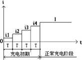
见图2,充电初期当测得蓄电池的实时内阻Rt处于电解液的温度为-15℃至0℃时的内阻之间时,分别以i1=0.01C、i2=0.02C、i3=0.04C和i4=0.06C的充电电流对该蓄电池充电各30分钟(即T=30分钟),若在该过程(即图2中的“充电初期”)中测得Rt≤RT,则立即采用0.1C的充电电流进行恒流充电(即进入图2中的“正常充电阶段”),直至蓄电池的电压到达所述析气电压值时,进行恒压充电;当该蓄电池的电压到达额定饱和电压时,进行浮充充电一段时间后结束充电。若在该过程结束时Rt仍然大于RT,则采用0.06-0.08C的充电电流对该蓄电池持续恒流充电,直至测得Rt≤RT,则立即采用0.1C的充电电流进行恒流充电,直至蓄电池的电压到达所述析气电压值时,进行恒压充电;当该蓄电池的电压到达额定饱和电压时,进行浮充充电一段时间后结束充电。As shown in Figure 2, when the measured real-time internal resistance Rt of the battery is between -15°C and 0°C at the initial stage of charging, take i1 =0.01C, i2 =0.02C, The charging current of i3 =0.04C and i4 =0.06C charges the battery for 30 minutes each (ie T=30 minutes), if Rt ≤ RT , then immediately use a charging current of 0.1C to carry out constant current charging (that is, enter the "normal charging stage" in Figure 2), until the battery voltage reaches the gas evolution voltage value, then carry out constant voltage charging; when the battery When the voltage reaches the rated saturation voltage, the float charge will be carried out for a period of time and then the charge will end. If Rt is still greater than RT at the end of the process, use a charging current of 0.06-0.08C to continuously charge the battery with a constant current until it is measured that Rt ≤ RT , then immediately use a charging current of 0.1C for constant current Charge until the battery voltage reaches the gassing voltage value, then perform constant-voltage charging; when the battery voltage reaches the rated saturation voltage, perform float charging for a period of time and then end charging.
充电初期当测得蓄电池的实时内阻Rt大于电解液的温度为-15℃的内阻时,分别以0.01C、0.02C、0.03C、0.04C、0.05C和0.06C的充电电流对该蓄电池充电各30分钟,或依次充电40分钟、35分钟、30分钟、28分钟、25分钟和20分钟,即:电解液的温度越低,对该蓄电池充电的时段数可适当增加,且各时段内充电电流依次逐渐小幅增加;若在该过程中测得Rt≤RT,则立即采用0.1C的充电电流进行恒流充电。若在该过程结束时Rt仍然大于RT,则采用0.06-0.08C的充电电流对该蓄电池持续恒流充电,直至测得Rt≤RT,则立即采用0.1C的充电电流进行恒流充电,直至蓄电池的电压到达所述析气电压值时,进行恒压充电;当该蓄电池的电压到达额定饱和电压时,浮充充电一段时间后结束充电。When the measured real-time internal resistance Rt of the battery is greater than the internal resistance of the electrolyte at -15°C at the initial stage of charging, charge currents of 0.01C, 0.02C, 0.03C, 0.04C, 0.05C and 0.06C to the battery Charge the battery for 30 minutes each, or sequentially charge for 40 minutes, 35 minutes, 30 minutes, 28 minutes, 25 minutes, and 20 minutes. The internal charging current gradually increases slightly in turn; if Rt ≤ RT is measured during this process, a charging current of 0.1C is immediately used for constant current charging. If Rt is still greater than RT at the end of the process, use a charging current of 0.06-0.08C to continuously charge the battery with a constant current until it is measured that Rt ≤ RT , then immediately use a charging current of 0.1C for constant current Charge until the voltage of the battery reaches the gassing voltage value, then perform constant-voltage charging; when the voltage of the battery reaches the rated saturation voltage, finish charging after a period of float charging.
本发明在初始充电期采用多阶段小电流充电的方法,不仅完全在正负电极低温情况下的接电能力范围之内,而且利用了小电流产生的热量Q(Q=i2Rt),使得栅格温度逐步升高后,再逐步加大电流,蓄电池电压上升得非常缓慢,且在阀控电池内部温度发热到正常充电所需的温度(,该温度一般为25℃,此时内阻已在正常范围内)再转为大电流充电(一般为0.1C,也可采用0.1C-0.25C之间的任意值),因此不会产生大量的热量而失水。The present invention adopts a multi-stage small current charging method in the initial charging period, which is not only fully within the range of the power connection capability of the positive and negative electrodes at low temperature, but also utilizes the heat Q (Q=i2 Rt) generated by the small current, so that After the grid temperature rises gradually, and then gradually increase the current, the battery voltage rises very slowly, and the internal temperature of the valve-controlled battery heats up to the temperature required for normal charging (the temperature is generally 25°C, and the internal resistance has already Within the normal range) and then switch to high current charging (generally 0.1C, any value between 0.1C-0.25C can also be used), so it will not generate a lot of heat and lose water.
开始充电时,采用固定大小的直流电对蓄电池充电并预热电解液,在固定PWM脉宽的情况下检测当前充电电流的大小,就可以得到当前被充电蓄电池的内阻(R=V/I)。When starting to charge, use a fixed size of direct current to charge the battery and preheat the electrolyte, and detect the size of the current charging current under the condition of a fixed PWM pulse width to obtain the current internal resistance of the battery being charged (R=V/I) .
在开始充电时,首先由单片机检测当前蓄电池内阻的大小,从而决定在充电初期各个小电流阶段时间T的长短,以100AH阀控铅酸蓄电池为例,若每只蓄电池内阻低于8mΩ(R1),则T为零;若每只蓄电池内阻高于11 mΩ(R2),则T为30分钟;80AH阀控铅酸蓄电池为例,每只蓄电池内阻低于10mΩ,则T为零;高于13 mΩ,则T为30分钟;20AH阀控铅酸蓄电池为例,每只蓄电池内阻低于35mΩ,则T为零;高于48 mΩ,则T为30分钟等;前述各例充电电流i1、i2、i3、i4、I均分别为0.01C、0.02C、0.04C、0.06C、0.1C(C为蓄电池标称容量)大小的充电电流。At the beginning of charging, firstly, the single-chip microcomputer detects the size of the internal resistance of the current battery, so as to determine the length of the time T of each small current stage in the initial stage of charging. Taking a 100AH valve-regulated lead-acid battery as an example, if the internal resistance of each battery is lower than 8mΩ ( R1), then T is zero; if the internal resistance of each battery is higher than 11 mΩ (R2), then T is 30 minutes; 80AH valve-regulated lead-acid battery as an example, if the internal resistance of each battery is lower than 10mΩ, then T is zero ; higher than 13 mΩ, then T is 30 minutes; 20AH valve-regulated lead-acid battery as an example, if the internal resistance of each battery is lower than 35mΩ, then T is zero; higher than 48 mΩ, then T is 30 minutes; The charging currents i1, i2, i3, i4, and I are respectively 0.01C, 0.02C, 0.04C, 0.06C, and 0.1C (C is the nominal capacity of the battery).
蓄电池在充电过程中,析氧和析氢电压与蓄电池电解液的温度有关,即:During the charging process of the battery, the oxygen evolution and hydrogen evolution voltage are related to the temperature of the battery electrolyte, namely:
V析氧= n×2. 35-0.004×n×( Ta-25) (1)Voxygen evolution = n×2. 35-0.004×n×(Ta-25) (1)
V析氢= n×2. 42-0.004×n×( Ta-25) (2)Vhydrogen evolution = n×2. 42-0.004×n×(Ta-25) (2)
式中:n为串行连接的电池栅格的数量,Ta为蓄电池电解液的温度;In the formula: n is the number of battery grids connected in series, and Ta is the temperature of the battery electrolyte;
即在25 ℃环境下,当n = 18 时,析氧电压V析氧= 42. 3 V ,析氢电压V析氢= 43. 56 V ,且随着温度升高而减小,温度降低而增大。That is, in the environment of 25 ℃, when n = 18, the oxygenevolution voltage V = 42.3 V, and the hydrogenevolution voltage V = 43.56 V, and they decrease as the temperature increases and increase as the temperature decreases. .
初始充电阶段对电池进行固定脉冲宽度后形成的固定电压充电,根据蓄电池的充电电压和电流得出蓄电池实时的内阻,然后根据该蓄电池内阻值与温度的关系曲线(该曲线可通过实验得出)得出该蓄电池中的电解液的温度,当测得蓄电池的电压值达到析气电压值(析气电压值为蓄电池的常数,可通过实验测量)时,恒流充电结束。然后进行恒压充电;当该蓄电池的电压到达额定饱和电压时,进行浮充充电一段时间后结束充电。In the initial charging stage, the battery is charged with a fixed voltage formed after a fixed pulse width, and the real-time internal resistance of the battery is obtained according to the charging voltage and current of the battery, and then according to the relationship curve between the internal resistance of the battery and temperature (this curve can be obtained through experiments) output) to get the temperature of the electrolyte in the battery, when the measured voltage value of the battery reaches the gassing voltage value (the gassing voltage value is a constant of the battery, which can be measured by experiment), the constant current charging ends. Then carry out constant voltage charging; when the voltage of the storage battery reaches the rated saturation voltage, carry out floating charging for a period of time and then end charging.
由于恒流充电到恒压充电的过渡根据实测电压决定,这样可根据不同电池的放电深度,决定恒流充电阶段的时间,防止放电深度较浅的电池过充电。 另外,为了防止某些品质已受影响的电池(即已失效或即将失效的蓄电池)无法达到规定的电压值,恒流充电阶段设置最长充电时间(如:16个小时)。 如果已到达最长充电时间,还未达到指定的电量,则停止充电。Since the transition from constant current charging to constant voltage charging is determined by the measured voltage, the time of the constant current charging phase can be determined according to the discharge depth of different batteries to prevent overcharging of batteries with shallow discharge depths. In addition, in order to prevent some batteries whose quality has been affected (that is, batteries that have failed or are about to fail) from reaching the specified voltage value, the maximum charging time (eg: 16 hours) is set in the constant current charging stage. If the maximum charging time has been reached and the specified power has not been reached, the charging will stop.
(实施例2)(Example 2)
见图3-6,应用上述阀控式铅酸蓄电池的预热充电方法的充电装置,包括:整流供电电路1、与该整流供电电路1的电源输出端相连的用于向蓄电池提供充电电源的脉冲功率放大及变压电路4、用于检测充电电流和电压的充电取样回路3和用于控制所述脉冲功率放大及变压电路4的输出电压的充电控制电路2;充电控制电路2适于通过所述充电取样回路3测得的充电电流和固定的充电电压计算出蓄电池的实时内阻Rt,以根据Rt与RT的大小关系,采用实施例1中相应的充电步骤。See Fig. 3-6, the charging device that applies the preheating charging method of the above-mentioned valve-regulated lead-acid battery includes: a rectification
整流电路1的输入端与交流电网连接,整流电路1的第一直流输出端与脉冲功率放大及变压电路4的电源输入端相连,脉冲功率放大及变压电路4的电源输出端与充电取样回路3的电源输入端连接,充电取样回路3的电源输出端用于与蓄电池相连,充电取样回路3的电压采样信号输出端和电流采样信号输出端分别与充电控制电路2的电压采样信号输入端和电流采样信号输入端相连;充电控制电路2的脉冲信号输出端与脉冲功率放大及变压电路4的控制信号输入端相连4。The input end of the
见图4,充电控制电路2包括有单片机IC1、稳压集成块IC2、直流运放器IC3、缓冲放大器IC4、电阻R4~R6、R8~R10和电容C2,单片机IC1是内部具有FLASH程序存储器和4路A/D转换器的P87LPC767单片机,直流运放器是型号为LM358的集成电路,缓冲放大器是型号为4050集成电路;稳压集成块IC2的输入端通过电阻R4与整流电路1的一输出端连接,稳压集成块IC2的输出端与单片机IC1的电源VCC端连接,稳压集成块IC2的输出端还与电解电容C2的正极连接,电解电容C2的正极接地;电阻R1与变压器T的连接处作为电压信号采样端通过电阻R5与直流运放器IC3的正输入端连接,直流运放器IC3的负输入端通过电阻R6接地,直流运放器IC3的输出端通过电阻R8与单片机IC1的信号输入端AD1连接,直流运放器IC3的输出端还通过电阻R7与其负输入端连接;电阻R2、R3的连接处作为信号采样端与单片机IC1的信号端AD0连接;单片机IC1的控制信号输出端通过电阻R9与缓冲放大器IC4的输入端连接,缓冲放大器IC4的输出端通过电阻R10与脉冲功率放大及变压电路4的控制信号输入端连接。As shown in Fig. 4, the charging control circuit 2 includes a single-chip microcomputer IC1, a voltage stabilizing integrated block IC2, a DC operational amplifier IC3, a buffer amplifier IC4, resistors R4-R6, R8-R10, and a capacitor C2. The single-chip microcomputer IC1 has a FLASH program memory and The P87LPC767 single-chip microcomputer of the 4-way A/D converter, the DC operational amplifier is an integrated circuit of the model LM358, and the buffer amplifier is an integrated circuit of the model 4050; the input terminal of the voltage stabilizing integrated block IC2 is connected with an output of the rectifier circuit 1 through the resistor R4 The output terminal of the voltage stabilizing integrated block IC2 is connected to the power supply VCC terminal of the single chip microcomputer IC1, the output terminal of the stabilizing integrated block IC2 is also connected to the positive pole of the electrolytic capacitor C2, and the positive pole of the electrolytic capacitor C2 is grounded; the resistance R1 and the transformer T The connection is used as a voltage signal sampling terminal to connect to the positive input terminal of the DC operational amplifier IC3 through the resistor R5, the negative input terminal of the DC operational amplifier IC3 is grounded through the resistor R6, and the output terminal of the DC operational amplifier IC3 is connected to the single-chip microcomputer IC1 through the resistor R8 The signal input terminal AD1 is connected, and the output terminal of the DC operational amplifier IC3 is also connected to its negative input terminal through the resistor R7; the connection of the resistors R2 and R3 is used as the signal sampling terminal to connect with the signal terminal AD0 of the single-chip microcomputer IC1; the control signal of the single-chip microcomputer IC1 The output terminal is connected to the input terminal of the buffer amplifier IC4 through the resistor R9, and the output terminal of the buffer amplifier IC4 is connected to the control signal input terminal of the pulse power amplification and voltage transformation circuit 4 through the resistor R10.
脉冲功率放大及变压电路4包括:开关管VMOS和变压器T;开关管VMOS的电流输入端和电流输出端分别与整流电路1的输出端和变压器T的初级线圈连接,开关管VMOS的控制端与充电控制电路2的控制信号输出端连接;变压器T的次级与作为输出端与充电取样回路3的输入端连接。The pulse power amplification and voltage transformation circuit 4 includes: a switch tube VMOS and a transformer T; the current input terminal and the current output terminal of the switch tube VMOS are respectively connected to the output terminal of the
电取样回路3包括有整流二极管D1、电解电容C1、采样电阻R1和分压电阻R2、R3;所述的整流二极管D1的正极与变压器T的次级线圈的一端连接,整流二极管D1的负极与继电器KA的常开触点的一端相连,该常开触点的另一端与待充电的蓄电池的正极相连;电解电容C1的正极与整流二极管D1的负极连接,电解电容C1的负极接地;分压电阻R2、R3串联后一端与整流二极管D1的负极连接,另一端接地;采样电阻R1的一端与变压器T的次级线圈的另一端连接,采样电阻R1的另一端和蓄电池的负极接地。图4中的接头X3、X4分别接蓄电池的正、负极。The electrical sampling loop 3 includes a rectifying diode D1, an electrolytic capacitor C1, a sampling resistor R1 and voltage dividing resistors R2, R3; the anode of the rectifying diode D1 is connected to one end of the secondary coil of the transformer T, and the negative pole of the rectifying diode D1 is connected to One end of the normally open contact of the relay KA is connected, and the other end of the normally open contact is connected to the positive pole of the battery to be charged; the positive pole of the electrolytic capacitor C1 is connected to the negative pole of the rectifier diode D1, and the negative pole of the electrolytic capacitor C1 is grounded; After resistors R2 and R3 are connected in series, one end is connected to the negative pole of the rectifier diode D1, and the other end is grounded; one end of the sampling resistor R1 is connected to the other end of the secondary coil of the transformer T, and the other end of the sampling resistor R1 is grounded to the negative pole of the battery. Connectors X3 and X4 in Figure 4 are respectively connected to the positive and negative poles of the storage battery.
由于检测蓄电池内阻的前提是在固定电压下检测充电电流大小,而开关电源式的充电装置输出的充电电流、电压是由单片机产生的PWM脉冲来控制的,脉冲开启和关闭变压器T的初级上的电源,形成初级励磁再耦合到次级,然后经整流形成充电电压和充电电流。由于PWM脉冲经过了放大、变压、整流等环节,即使被充电的蓄电池的内阻相同,空载时,同样占空比的PWM脉冲,不一定能产生同样的充电电压和充电电流。Since the premise of detecting the internal resistance of the battery is to detect the charging current at a fixed voltage, the charging current and voltage output by the switching power supply charging device are controlled by the PWM pulse generated by the single-chip microcomputer, and the pulse turns on and off the primary side of the transformer T. The power supply forms the primary excitation and then couples to the secondary, and then is rectified to form the charging voltage and charging current. Since the PWM pulse has been amplified, transformed, and rectified, even if the internal resistance of the battery being charged is the same, the PWM pulse with the same duty cycle may not be able to generate the same charging voltage and charging current when it is no-load.
因此,为了较准确地检测蓄电池的实时内阻Rt,采用的优选方案如下:Therefore, in order to detect the real-time internal resistance Rt of the battery more accurately, the optimal scheme adopted is as follows:
首先在空载不充电的情况下(即:采用继电器KA先断开蓄电池和充电装置),使用单片机产生脉宽由零逐渐增加的PWM脉冲信号,以探测在该脉冲下充电装置输出的充电电压的高低,若该充电电压到达设定的标准电压(该电压比待充电蓄电池的电压高1-2V),则停止PWM脉冲宽度的变化,然后再控制继电器KA接通蓄电池,并在该PWM脉冲宽度下充电;此时,根据充电电流,即可得出蓄电池的实时内阻Rt。然后根据Rt与RT的大小关系,采用相应的充电程序。First, in the case of no-load charging (i.e. use the relay KA to disconnect the battery and charging device first), use a single-chip microcomputer to generate a PWM pulse signal with a pulse width gradually increasing from zero to detect the charging voltage output by the charging device under this pulse If the charging voltage reaches the set standard voltage (the voltage is 1-2V higher than the voltage of the battery to be charged), the change of the PWM pulse width will be stopped, and then the relay KA will be controlled to connect the battery, and the PWM pulse will Charge at a wide range; at this time, according to the charging current, the real-time internal resistance Rt of the battery can be obtained. Then according to the size relationship between Rt andRT , adopt the corresponding charging procedure.
探测所述标准电压的方法是:采用继电器KA先断开蓄电池和充电装置,充电装置的空载输出电压经过分压电阻R2、R3分压后作为比较器IC5的负输入,固定标准电压由2.5V精密基准电压源IC6 (型号为MC1403)作为比较器IC5的正输入,逐渐增加PWM宽度,使比较器IC5的负端电压逐渐升高,直到比较器IC5的负输入电压超过固定标准电压后,比较器IC5有输出,使得单片机IC1的INT0(P1.3)中断口产生中断后停止PWM宽度的变化,IC7与IC4是同相缓冲放大器, IC7将单片机IC1的P0.2口输出的高低电平放大后驱动继电器KA的线圈,以控制继电器KA的通断,从而控制本充电装置连接或断开蓄电池。该方法为初始充电电压的标定。得到标准电压后,通过所述P0.2口接通继电器KA并检测出该标准电压下电流的大小即可得出蓄电池的内阻,再根据内阻大小,采用实施例1中相应的充电程序。The method for detecting the standard voltage is: use the relay KA to first disconnect the storage battery and the charging device, the no-load output voltage of the charging device will be used as the negative input of the comparator IC5 after being divided by the voltage dividing resistors R2 and R3, and the fixed standard voltage is changed from 2.5 V precision reference voltage source IC6 (model MC1403) is used as the positive input of comparator IC5, and gradually increases the PWM width, so that the negative terminal voltage of comparator IC5 gradually increases until the negative input voltage of comparator IC5 exceeds the fixed standard voltage. The comparator IC5 has an output, so that the INT0 (P1.3) interrupt port of the single-chip microcomputer IC1 stops the change of the PWM width after an interrupt. IC7 and IC4 are in-phase buffer amplifiers, and IC7 amplifies the high and low levels output by the P0.2 port of the single-chip microcomputer IC1. Afterwards, the coil of the relay KA is driven to control the on-off of the relay KA, thereby controlling the charging device to connect or disconnect the storage battery. This method is the calibration of the initial charging voltage. After obtaining the standard voltage, connect the relay KA through the P0.2 port and detect the magnitude of the current under the standard voltage to obtain the internal resistance of the battery, and then according to the magnitude of the internal resistance, use the corresponding charging procedure in Example 1 .
首先由交流市电通过整流和滤波提供恒稳直流电压进行电路供电;PWM脉冲产生及定时控制电路则控制初始充电电流大小、时间长短和正常充电电流的大小;充电及温度、电流、电压取样回路用来产生充电电流、采样初始充电期环境温度、采样充电电流大小和充电期间当前电压高低;脉冲功率放大及变压电路,将单片机并行口输出的PWM脉冲放大后推动大功率VMOS管工作,开关高频变压器将整流后高压变压为充电所需电压和电流。First, the AC mains provides constant and stable DC voltage through rectification and filtering to power the circuit; the PWM pulse generation and timing control circuit controls the initial charging current, the length of time and the size of the normal charging current; charging and temperature, current, voltage sampling loop Used to generate charging current, sample the ambient temperature during the initial charging period, sample the size of the charging current and the current voltage during charging; pulse power amplification and voltage transformation circuit, amplify the PWM pulse output by the parallel port of the single-chip microcomputer to drive the high-power VMOS tube to work, switch The high-frequency transformer transforms the rectified high voltage into the voltage and current required for charging.
单片机IC1的并行口P0.1发出PWM脉冲,脉冲频率约为20KHz。PWM脉冲提供开关电源脉冲变压器T所需的激励脉冲频率,使充电器产生充电所需脉冲峰值电流,在每个PWM脉冲频率不变的情况下,脉冲宽度窄、脉间宽度宽则产生充电电流小,否则充电电流大。脉宽脉间长度大小,由P0.1口的PWM发生器软件赋值改变,但脉冲频率不变,即改变PWM脉冲脉宽和脉间大小就可以控制充电电流的大小。定时则由软件循环或单片机内部定时器完成。单片机产生20KHz脉冲,经过电阻R9隔离和IC4的同相缓冲放大后,经电阻R10限流后直接驱动开关管VMOS进行开关通断,从而将经过交流220V整流得到的直流高压变换为开关电源所需的脉冲电压,开关电源脉冲变压器T的次级得到经过变压过的较低的脉冲电压,经整流二极管D1整流及电解电容C1滤波后,提供蓄电池充电所需电压。The parallel port P0.1 of the single-chip microcomputer IC1 sends out PWM pulses, and the pulse frequency is about 20KHz. The PWM pulse provides the excitation pulse frequency required by the pulse transformer T of the switching power supply, so that the charger generates the pulse peak current required for charging. Under the condition that the frequency of each PWM pulse remains unchanged, the narrow pulse width and wide pulse width will generate charging current. Small, otherwise the charging current is large. The pulse width and length between pulses are changed by the PWM generator software at P0.1 port, but the pulse frequency remains unchanged, that is, changing the PWM pulse width and pulse-to-pulse size can control the size of the charging current. Timing is completed by the software loop or the internal timer of the one-chip computer. The single-chip microcomputer generates 20KHz pulses, which are isolated by resistor R9 and in-phase buffered and amplified by IC4, and then directly drive the switch tube VMOS to switch on and off after being limited by resistor R10, so as to convert the DC high voltage obtained through
充电电流大小由采样电阻R1一端(即图4中的接点Q)的电压,作为直流运放器IC3的正端输入,经直流运放器IC3的放大后被单片机IC1的A/D1端采集。充电期间电压采样是将充电电压经过分压电阻R2、R3分压后由单片机IC1的A/D0端采集,以得到充电电压值,并根据此充电电压值及时转为恒压充电和浮充充电,到达设定电压值后,停止整个充电过程。The charging current is determined by the voltage at one end of the sampling resistor R1 (that is, the contact point Q in Figure 4), which is used as the positive input of the DC operational amplifier IC3, and is collected by the A/D1 terminal of the single-chip microcomputer IC1 after being amplified by the DC operational amplifier IC3. The voltage sampling during charging is to collect the charging voltage by the A/D0 terminal of the single chip IC1 after being divided by the voltage dividing resistors R2 and R3, so as to obtain the charging voltage value, and convert it to constant voltage charging and floating charging in time according to the charging voltage value , after reaching the set voltage value, stop the whole charging process.
单片机IC1还可使用内部具有FLASH程序存储器和4路A/D转换器和4路PWM脉冲发生器的P87LPC768芯片,运放器IC3可使用LM358集成电路,缓冲器IC4、IC7使用4050集成电路,稳压器IC2使用7805集成电路。The microcontroller IC1 can also use the P87LPC768 chip with FLASH program memory, 4-way A/D converter and 4-way PWM pulse generator inside, the op amp IC3 can use the LM358 integrated circuit, and the buffer IC4 and IC7 can use the 4050 integrated circuit. Compressor IC2 uses 7805 integrated circuit.
上述实施例仅仅是为清楚地说明本发明所作的举例,而并非是对本发明的实施方式的限定。对于所属领域的普通技术人员来说,在上述说明的基础上还可以做出其它不同形式的变化或变动。这里无需也无法对所有的实施方式予以穷举。而这些属于本发明的精神所引伸出的显而易见的变化或变动仍处于本发明的保护范围之中。The above-mentioned embodiments are only examples for clearly illustrating the present invention, rather than limiting the implementation of the present invention. For those of ordinary skill in the art, other changes or changes in different forms can be made on the basis of the above description. It is not necessary and impossible to exhaustively list all the implementation manners here. And these obvious changes or modifications derived from the spirit of the present invention are still within the protection scope of the present invention.
Claims (7)
Priority Applications (1)
| Application Number | Priority Date | Filing Date | Title |
|---|---|---|---|
| CN 201110039359CN102064589B (en) | 2011-02-16 | 2011-02-16 | Charging device for valve-regulated lead-acid battery |
Applications Claiming Priority (1)
| Application Number | Priority Date | Filing Date | Title |
|---|---|---|---|
| CN 201110039359CN102064589B (en) | 2011-02-16 | 2011-02-16 | Charging device for valve-regulated lead-acid battery |
Related Child Applications (1)
| Application Number | Title | Priority Date | Filing Date |
|---|---|---|---|
| CN201210370722.7ADivisionCN102856603B (en) | 2011-02-16 | 2011-02-16 | Preheating and charging method of valve-control type lead-acid storage battery capable of avoiding water loss in low-temperature charging |
Publications (2)
| Publication Number | Publication Date |
|---|---|
| CN102064589A CN102064589A (en) | 2011-05-18 |
| CN102064589Btrue CN102064589B (en) | 2013-02-27 |
Family
ID=43999750
Family Applications (1)
| Application Number | Title | Priority Date | Filing Date |
|---|---|---|---|
| CN 201110039359Expired - Fee RelatedCN102064589B (en) | 2011-02-16 | 2011-02-16 | Charging device for valve-regulated lead-acid battery |
Country Status (1)
| Country | Link |
|---|---|
| CN (1) | CN102064589B (en) |
Families Citing this family (3)
| Publication number | Priority date | Publication date | Assignee | Title |
|---|---|---|---|---|
| DE112012003131T5 (en)* | 2011-07-27 | 2014-04-10 | Mitsubishi Electric Corporation | Charge control device and charge control method for a secondary battery |
| CN111157907B (en)* | 2019-12-30 | 2022-07-05 | Oppo广东移动通信有限公司 | Detection method and device, charging method and device, electronic equipment, storage medium |
| CN113612279B (en)* | 2021-08-04 | 2024-02-09 | 北京泰和九思科技有限公司 | Gradient pulse current high-efficiency low-temperature quick charging device |
Family Cites Families (4)
| Publication number | Priority date | Publication date | Assignee | Title |
|---|---|---|---|---|
| UA59019C2 (en)* | 2002-12-06 | 2007-01-15 | Viktor Oleksandrov Dzenzerskyi | Method for fast forming accumulator batteries by increased current |
| CN101237071A (en)* | 2007-02-03 | 2008-08-06 | 江苏双登集团有限公司 | Charging method for valve-controlled sealed lead-acid storage battery |
| US8174242B2 (en)* | 2008-04-10 | 2012-05-08 | Iks Co., Ltd. | Apparatus and method for pre-charging in charging/discharging equipment for an energy-storage device |
| CN101593855B (en)* | 2009-07-02 | 2010-12-01 | 马贵龙 | Lead-acid cell charge method controlled by microcomputer |
- 2011
- 2011-02-16CNCN 201110039359patent/CN102064589B/ennot_activeExpired - Fee Related
Also Published As
| Publication number | Publication date |
|---|---|
| CN102064589A (en) | 2011-05-18 |
Similar Documents
| Publication | Publication Date | Title |
|---|---|---|
| CN102136613B (en) | Valve-regulated lead-acid battery equalizing charge method | |
| CN102110863B (en) | Battery temperature measurement and charging method | |
| CN104282965B (en) | A kind of lithium ion battery self-heating apparatus and method | |
| CN108777339B (en) | A kind of lithium-ion battery pulse discharge self-heating method and device | |
| CN103117421A (en) | Low-temperature battery charging method | |
| CN102130368B (en) | Preheating charging method of valve-controlled type lead-acid storage battery | |
| CN104935045A (en) | A battery pack equalization method for an energy storage system using a nickel-based secondary battery | |
| CN201113410Y (en) | Electric power driven car battery charging protector | |
| CN110085947A (en) | A kind of quick self-heating method of battery cell, system and device | |
| CN103138021A (en) | Battery charging method | |
| CN203721843U (en) | Low-temperature self-heating circuit for power lithium ion battery module | |
| CN107666167A (en) | A kind of novel three-stage charging management method and device | |
| CN206878144U (en) | Power battery AC charging and discharging low temperature heating system | |
| CN102157975A (en) | Intelligent charging system of lead acid batteries and charging method | |
| CN205693385U (en) | Battery charger | |
| CN201674260U (en) | An intelligent charger | |
| CN103997108A (en) | Electric automobile lead acid battery charger | |
| CN102723762A (en) | Lithium ion storage battery formation circuit | |
| CN102064589B (en) | Charging device for valve-regulated lead-acid battery | |
| CN102856603B (en) | Preheating and charging method of valve-control type lead-acid storage battery capable of avoiding water loss in low-temperature charging | |
| WO2021114683A1 (en) | Charger and charging method therefor | |
| CN204131199U (en) | A kind of control circuit of battery charger | |
| CN104659830A (en) | Novel intelligent charger | |
| CN102136614A (en) | Self-adapting charging method for valve-regulated lead-acid storage battery | |
| CN111092271B (en) | Low-temperature charging method for lithium ion battery |
Legal Events
| Date | Code | Title | Description |
|---|---|---|---|
| C06 | Publication | ||
| PB01 | Publication | ||
| C10 | Entry into substantive examination | ||
| SE01 | Entry into force of request for substantive examination | ||
| C14 | Grant of patent or utility model | ||
| GR01 | Patent grant | ||
| C56 | Change in the name or address of the patentee | Owner name:JIANGSU UNIVERSITY OF TECHNOLOGY Free format text:FORMER NAME: JIANGSU TECHNOLOGY NORMAL COLLEGE | |
| CP03 | Change of name, title or address | Address after:213015 Changzhou Province in the Clock Tower District, Jiangsu, Wu Road, No. 1801 Patentee after:Jiangsu University of Technology Address before:213000 Changzhou Province in the Clock Tower District, Jiangsu, Wu Road, No. 1801 Patentee before:Jiangsu Teachers University of Technology | |
| ASS | Succession or assignment of patent right | Owner name:JIANGSU UNIVERSITY OF TECHNOLOGY Effective date:20131114 Owner name:NANTONG JINNIU MACHINERY MANUFACTURE CO., LTD. Free format text:FORMER OWNER: JIANGSU UNIVERSITY OF TECHNOLOGY Effective date:20131114 | |
| C41 | Transfer of patent application or patent right or utility model | ||
| COR | Change of bibliographic data | Free format text:CORRECT: ADDRESS; FROM: 213015 CHANGZHOU, JIANGSU PROVINCE TO: 226600 NANTONG, JIANGSU PROVINCE | |
| TR01 | Transfer of patent right | Effective date of registration:20131114 Address after:226600, Jiangsu province Nantong city Haian county old dam Town Industrial Park Patentee after:NANTONG JINNIU MACHINERY MANUFACTURE CO., LTD. Patentee after:Jiangsu University of Technology Address before:213015 Changzhou Province in the Clock Tower District, Jiangsu, Wu Road, No. 1801 Patentee before:Jiangsu University of Technology | |
| CF01 | Termination of patent right due to non-payment of annual fee | Granted publication date:20130227 Termination date:20200216 | |
| CF01 | Termination of patent right due to non-payment of annual fee |