CN102062713B - Device for testing high-temperature load-carrying properties of aluminum and aluminum alloy electric power apparatuses of power transmission line - Google Patents
Device for testing high-temperature load-carrying properties of aluminum and aluminum alloy electric power apparatuses of power transmission lineDownload PDFInfo
- Publication number
- CN102062713B CN102062713BCN 201010582453CN201010582453ACN102062713BCN 102062713 BCN102062713 BCN 102062713BCN 201010582453CN201010582453CN 201010582453CN 201010582453 ACN201010582453 ACN 201010582453ACN 102062713 BCN102062713 BCN 102062713B
- Authority
- CN
- China
- Prior art keywords
- temperature
- aluminum
- rod
- aluminum alloy
- testing
- Prior art date
- Legal status (The legal status is an assumption and is not a legal conclusion. Google has not performed a legal analysis and makes no representation as to the accuracy of the status listed.)
- Active
Links
Images


Landscapes
- Investigating Strength Of Materials By Application Of Mechanical Stress (AREA)
Abstract
Translated fromChinese
Description
Translated fromChinese技术领域technical field
本发明涉及测试技术领域,尤其涉及电力器材高温承载性能测试装置,具体地说是一种输电线路铝及铝合金电力器材高温承载性能测试装置。The invention relates to the technical field of testing, in particular to a device for testing the high-temperature load-bearing performance of electric equipment, in particular to a device for testing the high-temperature load-bearing performance of aluminum and aluminum alloy power equipment for transmission lines.
背景技术Background technique
目前相关国家标准中对铝及铝合金电力器材的破坏强度测试是在常温下进行的,但随着输送容量的不断提高,导线及与其配套的电力器材的运行温度也在不断提升。在铝及铝合金器材的设计标准中,其强度按照最高使用温度为70℃时校核,而当器材与耐热导线相配套时,其运行温度可达200℃,接近了铝及铝合金的再结晶温度(软化温度)。而金属材料长期在高温下运行时,其强度一般会随着温度的升高而不断降低。At present, the destructive strength test of aluminum and aluminum alloy power equipment in the relevant national standards is carried out at room temperature, but with the continuous increase of transmission capacity, the operating temperature of the wire and its supporting power equipment is also increasing. In the design standards of aluminum and aluminum alloy equipment, its strength is checked according to the maximum operating temperature of 70°C, and when the equipment is matched with heat-resistant wires, its operating temperature can reach 200°C, which is close to that of aluminum and aluminum alloy. Recrystallization temperature (softening temperature). When metal materials are operated at high temperature for a long time, their strength will generally decrease with the increase of temperature.
现有的国内外对输电线路铝及铝合金电力器材的强度测试试验机都为在常温下进行,无高温加热装置,虽然部分试验机有载荷保持功能,但其载荷保持时间都比较短,无法长时间(400小时以上)地保持较高的载荷。因此现有的试验装置无法真实反映电力器材在实际运行状态下的破坏强度。Existing testing machines for strength testing of transmission line aluminum and aluminum alloy power equipment at home and abroad are all carried out at room temperature without high-temperature heating devices. Although some testing machines have a load holding function, their load holding time is relatively short and cannot Maintain a high load for a long time (over 400 hours). Therefore, the existing test devices cannot truly reflect the destructive strength of electrical equipment under actual operating conditions.
发明内容Contents of the invention
本发明要解决的是现有技术存在的上述问题,旨在提供一种改进型的铝及铝合金电力器材高温承载性能装置,即能在常温下对试样进行短时间加载测试,同时也能满足在高温下对试样进行长时间加载测试。The present invention aims to solve the above-mentioned problems existing in the prior art, and aims to provide an improved high-temperature load-bearing performance device for aluminum and aluminum alloy power equipment, which can carry out short-time loading tests on samples at room temperature, and can also Meet the long-term loading test on the sample at high temperature.
为解决上述问题,本发明采用以下技术方案:输电线路铝及铝合金电力器材高温承载性能测试装置,包括控制计算机、高温箱、电液伺服拉力试验机、载荷保持控制系统和试样专用夹具,其特征在于所述的高温箱受控于温度控制器,并设置在拉力试验机的上夹头和下夹头之间;所述的专用夹具包括上拉杆和下拉杆,所述的上拉杆上端设有与拉力试验机上夹头连接的支承座,上拉杆的下端穿入所述的高温箱,端部设有一个试样连接件,所述的下拉杆的下端与拉力试验机的下夹头连接,上端穿入所述的高温箱,顶部设有一个试样连接头;In order to solve the above problems, the present invention adopts the following technical solutions: the high-temperature load-bearing performance test device for aluminum and aluminum alloy power equipment of transmission lines, including a control computer, a high-temperature box, an electro-hydraulic servo tensile testing machine, a load holding control system and a special fixture for samples, It is characterized in that the high-temperature box is controlled by a temperature controller and is arranged between the upper chuck and the lower chuck of the tensile testing machine; the special clamp includes an upper pull rod and a lower rod, and the upper end of the upper pull rod There is a supporting seat connected with the upper chuck of the tensile testing machine, the lower end of the upper pull rod penetrates into the high-temperature box, and a sample connector is provided at the end, and the lower end of the lower pull rod is connected with the lower chuck of the tensile testing machine. connection, the upper end penetrates into the high-temperature box, and a sample connector is provided on the top;
所述支承座通过两侧的楔面与试验机上夹头的楔面贴合;所述的上拉杆通过一个调心球与所述的支承座的内侧球面槽可调配合,支承座上开设有供上拉杆穿越的中心孔和球面槽,在所述球面槽放置所述的调心球,调心球的下表面为与支承座球面槽相等曲率的球面,使调心球和支承座的球面槽贴合,将上拉杆穿过调心球和支承座,在上拉杆上端旋入螺母,螺母的一个端面与调心球上表面贴合。The support seat fits the wedge surface of the chuck on the testing machine through the wedge surfaces on both sides; the upper pull rod can be adjusted and matched with the inner spherical groove of the support seat through a self-aligning ball, and the support seat is equipped with The central hole and spherical groove for the upper rod to pass through, place the self-aligning ball in the spherical groove, the lower surface of the self-aligning ball is a spherical surface with the same curvature as the spherical groove of the support seat, so that the spherical surface of the self-aligning ball and the support seat Fit the groove, pass the upper tie rod through the self-aligning ball and the support seat, screw the nut on the upper end of the upper tie rod, and one end surface of the nut fits on the upper surface of the self-aligning ball.
本发明的装置,在“机械负载+恒定高温+长时间”这三个条件下测试,模拟电力器材的实际运行环境,获得电力器材在高温承载条件下的强度损失率(与常温下强度进行对比),为耐高温电力器材提供相关的试验数据和设计依据。The device of the present invention is tested under the three conditions of "mechanical load + constant high temperature + long time", simulates the actual operating environment of electric equipment, and obtains the strength loss rate of electric equipment under high temperature load conditions (compared with the strength at normal temperature ), providing relevant test data and design basis for high temperature resistant power equipment.
本发明装置可以将被测试样加载到12~600kN之间的任一载荷,加温到室温~200℃之间的任一温度,并稳定地保持载荷在400小时以上,在载荷保持阶段结束后可继续加载直至试样破坏,获得被测电力器材在一定温度、一定载荷和一定保持时间后的破坏强度。The device of the present invention can load the tested sample to any load between 12 and 600kN, heat it to any temperature between room temperature and 200°C, and keep the load stably for more than 400 hours. It can continue to load until the sample is destroyed, and obtain the failure strength of the electric equipment under test after a certain temperature, a certain load and a certain holding time.
作为本发明的进一步改进,所述的上拉杆和试样连接件之间可脱卸连接。所述的下拉杆和试样连接头之间可脱卸连接。根据不同类型的试样,可以方便地更换试样连接件和试样连接头。As a further improvement of the present invention, the connection between the pull-up rod and the sample connecting piece is detachable. There is a detachable connection between the lower rod and the sample connection head. According to different types of samples, the sample connectors and sample connectors can be easily replaced.
作为本发明的再进一步改进,所述的上拉杆通过一个调心球与所述的支承座的内侧球面槽可调配合。上述调心球和支承座之间的球面配合结构能够将一对试验力自动调整成同轴,以减少试验力不同轴对试验结果带来的影响。As a further improvement of the present invention, the pull-up rod can be adjusted to cooperate with the inner spherical groove of the support seat through a self-aligning ball. The spherical fit structure between the above-mentioned self-aligning ball and the support seat can automatically adjust a pair of test forces to be coaxial, so as to reduce the influence of different test forces on the test results.
作为本发明的更进一步改进,所述的载荷保持控制系统与一个液压油冷却系统相连。由于试验机在工作时,其压强传递介质(液压油)需在高压下不断流动,而且受到电机、齿轮泵等工作时散发热量的影响,液压油在长时间循环工作时(长时间载荷保持状态),其温度会不断升高。为此,本发明引入了液压油冷却系统。将载荷保持控制系统的油缸侧面一端靠近底部的位置和油缸侧面另一端顶部位置开两个孔,前者连接冷却系统的进油口,后者连接冷却系统的出油口。液压油不断地通过冷却系统进行热交换达到降温目的,使本发明装置在长时间工作时保证油温的稳定,进一步提高了测试系统的可靠性。As a further improvement of the present invention, the load maintenance control system is connected with a hydraulic oil cooling system. Because the pressure transmission medium (hydraulic oil) of the testing machine needs to flow continuously under high pressure when the testing machine is working, and is affected by the heat emitted by the motor, gear pump, etc. ), its temperature will continue to rise. For this reason, the present invention has introduced hydraulic oil cooling system. Two holes are opened on the side of the oil cylinder of the load holding control system near the bottom and at the top of the other end of the oil cylinder. The former is connected to the oil inlet of the cooling system, and the latter is connected to the oil outlet of the cooling system. The hydraulic oil continuously conducts heat exchange through the cooling system to achieve the purpose of cooling, so that the device of the present invention can ensure the stability of the oil temperature when it works for a long time, and further improves the reliability of the test system.
附图说明Description of drawings
图1是本发明装置整体结构的示意图。Fig. 1 is a schematic diagram of the overall structure of the device of the present invention.
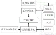
图2是本发明装置在工作时各系统之间的相互关系框图。Fig. 2 is a block diagram of the interrelationship between various systems of the device of the present invention when it is working.
图3是载荷保持系统构架框图。Figure 3 is a block diagram of the load holding system.
图4是高温箱2的安装示意图。FIG. 4 is a schematic diagram of the installation of the
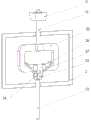
图5是试验机、高温箱和专用夹具的装配示意图。Figure 5 is a schematic diagram of the assembly of the testing machine, high temperature box and special fixtures.
图6是专用夹具的结构示意图。Fig. 6 is a schematic diagram of the structure of the special fixture.
图7是上拉杆组件的结构示意图。Fig. 7 is a structural schematic diagram of the pull-up rod assembly.
图8是上拉杆组件的装配示意图。Fig. 8 is a schematic diagram of the assembly of the pull-up rod assembly.
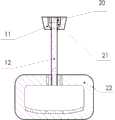
图9是下拉杆的结构示意图。Fig. 9 is a schematic diagram of the structure of the pull-down rod.
具体实施方式Detailed ways
参照图1,本发明的输电线路铝及铝合金电力器材高温承载性能测试装置,包括控制计算机4、高温箱2、电液伺服拉力试验机1、载荷保持控制系统7、液压油冷却系统8和电力器材破坏载荷测试专用夹具3,所述的高温箱2设置在拉力试验机1的上夹头9和下夹头10之间。Referring to Fig. 1, the high-temperature load-carrying performance test device of transmission line aluminum and aluminum alloy power equipment of the present invention includes a control computer 4, a high-
参照图2,在高温箱内设有一个固定的温度传感器和10个可活动的温度传感器。所述的10个可活动的温度传感器用于测量空间范围内和试样不同部位的温度值,用以判断被测试样的各个部分是否已经达到设定温度。所述的温度传感器感应的信号通过温度采集器输出给控制计算机进行计算和处理。所述的固定温度传感器用来感应箱内温度,并将信号输出给温度控制器,由温度控制器控制高温箱的箱内温度在一定的范围内。温度控制器采用可编程控制,可以分段设置升温速率和温度保持时间,即可实现温度的梯度升高和循环。Referring to Figure 2, there is a fixed temperature sensor and 10 movable temperature sensors in the high temperature box. The 10 movable temperature sensors are used to measure the temperature values of different parts of the sample in the space and to judge whether each part of the sample to be tested has reached the set temperature. The signal sensed by the temperature sensor is output to the control computer through the temperature collector for calculation and processing. The fixed temperature sensor is used to sense the temperature inside the box, and outputs the signal to the temperature controller, and the temperature controller controls the temperature inside the high-temperature box within a certain range. The temperature controller adopts programmable control, which can set the heating rate and temperature holding time in sections, so as to realize the gradient increase and cycle of temperature.
完成测试所需的载荷由电液伺服拉力试验机提供。为了保证试验机能够在长时间、高载荷条件下的稳定工作,本发明引入了液压油冷却系统8。所述的液压油冷却系统8和载荷保持控制系统7的油路联通,而载荷保持控制系统7与电液伺服拉力试验机1油路联通,这样,液压油不断地通过冷却系统进行热交换达到降温目的。The load required to complete the test is provided by an electro-hydraulic servo tensile testing machine. In order to ensure that the testing machine can work stably under long-term and high-load conditions, the present invention introduces a hydraulic
参照图3,电力器材的高温承载性能测试过程中需要对试样施加一恒定载荷,并保持这一载荷将超过400小时,上述条件由载荷保持系统提供。本发明中的载荷保持系统由位移传感器、拉力传感器和计算机控制载荷动态补偿系统组成。由位移传感器测量试样的形状变化,由拉力传感器感知试样的载荷波动,将这两者的变化同时输入计算机中的载荷动态补偿系统,由计算机控制系统输出补偿信号至电液伺服阀,通过电液伺服阀控制压力油缸的进油量大小,从而实现载荷的实时动态补偿和稳定。Referring to Figure 3, during the high temperature bearing performance test of electrical equipment, a constant load needs to be applied to the sample, and the load will be maintained for more than 400 hours. The above conditions are provided by the load holding system. The load maintaining system in the present invention is composed of a displacement sensor, a tension sensor and a computer-controlled load dynamic compensation system. The shape change of the sample is measured by the displacement sensor, the load fluctuation of the sample is sensed by the tension sensor, and the changes of the two are simultaneously input into the load dynamic compensation system in the computer, and the computer control system outputs the compensation signal to the electro-hydraulic servo valve, through The electro-hydraulic servo valve controls the oil intake of the pressure cylinder, so as to realize real-time dynamic compensation and stability of the load.
参照图4,高温箱2架设在可调节高度的支架上,并在支架上可进行前后移动,使箱体可以适应不同形状的试样和夹具。所述的支架包括垂直导轨18和横向悬臂17,所述高温箱2设置在所述的横向悬臂17的支板16上,横向悬臂17上还设有限位块15。所述的垂直导轨18固定在地面上,横向悬臂17可以沿垂直导轨18上下移动,在调整到位后由固定件19锁定。所述的高温箱2顶部和底部开设有供专用夹具3穿越的通孔14。Referring to Fig. 4, the
参照图5和图6,所述的专用夹具3包括上拉杆12和下拉杆13。所述的上拉杆12上端设有支承座11,与拉力试验机的上夹头9连接。上拉杆12的下端穿入高温箱2,端部设有一个连接件22,用于连接试样26。所述的下拉杆13的下端与拉力试验机的下夹头10连接,上端穿入高温箱2,顶部设有一个连接头24,用于固定试样26。Referring to FIG. 5 and FIG. 6 , the
参照图7、图8,本发明的上拉杆12上端设有支承座11,所述支承座11通过两侧的楔面与试验机上夹头9的楔面贴合,支承座11上开设有供上拉杆12穿越的中心孔和球面槽23,在所述球面槽23放置一个调心球21,调心球21的下表面也为与支承座球面槽23相等曲率的球面,使调心球21和支承座的球面槽23贴合。参照图8,上拉杆组件的装配过程如下:将上拉杆12穿过调心球21和支承座11,在上拉杆12上端旋入螺母20,螺母20的一个端面与调心球21上表面贴合。Referring to Fig. 7 and Fig. 8, the upper end of the pull-
试验时,要求试验机加载在试样上的一对拉力方向相反、大小相等,在上拉杆12下端受到偏离竖直向下的力时,上拉杆12将通过调心球21与支撑面之间的滑动,使上夹头9施加载荷的方向能随着下夹头10做微小的偏离而自动调整。可见,上述调心球21和支承座11之间的球面配合结构能够将一对试验力自动调整成同轴,以减少试验力不同轴对试验结果带来的影响。During the test, it is required that the direction of the pair of tensile forces loaded by the testing machine on the sample is opposite and equal in size. When the lower end of the
本发明所述的调心球21是一个相对广义的概念,可以是全球体或半球体,也可以是任何比率的球面,只要在底部具有部分球面,能够与支承座11形成转动配合即可。在本实施例中采用的是半球面结构。最好,所述的调心球21的上表面为平面,以便与螺母更好地配合。The self-aligning
另一个更为简单的实施方式,所述的调心球21通过焊接或螺纹连接直接与所述的上拉杆12固定,或者两者一体化成形,也能够实现自动调整同轴的功能。而且,可以省掉一个固定螺母,且装配也更为简单。In another simpler embodiment, the self-aligning
参照图7,所述的上拉杆12下端通过螺纹与连接件22连接。所述的连接件22的形状根据不同的试样结构进行设计。在本实施例中,试样26为悬垂线夹,连接件22为方形框体状夹具。Referring to FIG. 7 , the lower end of the pull-up
将框体22与悬垂线夹26接触部分的框体表面轮廓机加工成与悬垂线夹底部内表面紧密贴合,使施加在悬垂线夹内表面的为均布载荷而非集中应力,与悬垂线夹26的实际工作情况相吻合。同时将原先与悬垂线夹配套的U型挂板替换成下拉杆,大大简化了在装夹时的装配过程。且原先通过U型挂板连接下拉杆时,U型挂板只能经受单次测试,无法重复使用,采用一体式下拉杆时,将下拉杆上端设计成具有足够的受力支承面,可反复使用而不变形,同时将下拉杆下端设计成圆柱形,可将其直接夹持在试验机的下夹头10上。The frame body surface profile of the contact part of the
操作实例:Operation example:
将本发明的装置用于测试铸造铝合金悬垂线夹电力器材的一种,用于在铁塔上悬挂导线的高温承载性能时,首先将悬垂线夹的其他附件拆下,只将本体进行测试。按照图6所示进行装配和连接,将上拉杆12与框体22通过螺纹连接,将悬垂线夹26内表面与框体22下部贴合,将下拉杆13通过螺栓25与悬垂线夹的两个挂耳27相连。上拉杆12的下半部、框体22、悬垂线夹26和下拉杆13的上半部全部纳入高温箱2内,上下拉杆通过高温箱的上下两个面上直径为Φ50mm的通孔与试验机1的上下夹头9、10连接。待装夹完毕后,将高温箱上下通孔与拉杆之间的间隙用石棉封堵,并且关闭高温箱的门。The device of the present invention is used to test a kind of power equipment of cast aluminum alloy suspension wire clamp. When it is used to suspend the high temperature bearing performance of the wire on the iron tower, first remove other accessories of the suspension wire clamp, and only the main body is tested. Assembled and connected as shown in Figure 6, the
分别启动计算机和试验控制程序,高温箱温度控制系统和高温箱内的10路温度传感器,试验机电源和伺服开关。在高温箱控制系统面板上设定试验所需保持温度为200℃和保持时间为101小时。在试验控制程序中编写试样加载程序,如可设定试验机首先采用10mm/min的夹头分离速度,在载荷达到5kN时,以2mm/min位移速度加载,并在载荷达到50kN时停止加载,使载荷一直保持在50kN并持续100小时,在100小时后,继续加载直至试样破坏,程序将自动记录试样关于“位移-载荷”和“时间-载荷”的曲线,得到悬垂线夹在200℃高温下,持续承受50kN载荷100小时后,其破坏强度的值。通过对悬垂线夹在常温下和高温承载后的破坏强度对比,得到悬垂线夹在高温承载试验后的强度损失率,预测铸造铝合金悬垂线夹在与耐高温导线配套后的安全使用寿命。Start the computer and the test control program, the temperature control system of the high temperature box and the 10-way temperature sensor in the high temperature box, the power supply of the testing machine and the servo switch. On the control system panel of the high-temperature box, set the required holding temperature for the test as 200° C. and the holding time as 101 hours. Write the sample loading program in the test control program. For example, it can be set that the testing machine first adopts the chuck separation speed of 10mm/min, when the load reaches 5kN, loads at the displacement speed of 2mm/min, and stops loading when the load reaches 50kN , keep the load at 50kN for 100 hours, after 100 hours, continue to load until the sample is broken, the program will automatically record the curves of the sample about "displacement-load" and "time-load", and get the Under the high temperature of 200 ℃, the value of the breaking strength after continuously bearing the load of 50kN for 100 hours. By comparing the failure strength of the suspension wire clamp at normal temperature and high temperature load, the strength loss rate of the suspension wire clamp after the high temperature load test is obtained, and the safe service life of the cast aluminum alloy suspension wire clamp after matching with the high temperature resistant wire is predicted.
参照图9,本发明的另一种实施方式。所述的上拉杆12下端的试样连接件22为倒U形结构,所述的下拉杆13上端的连接头24为U形结构。这种结构夹具,用于测试连接金具类电力器材,如U型挂环和联板。图9中的试样26为U型挂环,倒U形连接件22和U形连接头24的开口方向垂直。上拉杆的倒U形连接件22通过螺栓28与U型挂环的挂耳相连,下拉杆的U形连接头24通过螺栓25与U型挂环的环体相连。Referring to Fig. 9, another embodiment of the present invention. The
图10中的试样26为联板,倒U形连接件22和U形连接头24的开口方向一致。上拉杆的倒U形连接件22通过螺栓28与联板的一端相连,下拉杆的U形连接头24通过螺栓25与联板的的另一端相连。由于上拉杆12可转动,因此,更换试样时无须更换夹具,只要调整上下拉杆之间的角度就行了。The
上拉杆12和试样连接件22采用可脱卸连接,可较为方便地更换夹具。如将测试悬垂线夹用的框体夹具旋下,装上用于测试联板的U形夹具即可。The pull-up
应该理解到的是:上述实施例只是对本发明的说明,而不是对本发明的限制,任何不超出本发明实质精神范围内的发明创造,均落入本发明的保护范围之内。It should be understood that: the above-mentioned embodiments are only descriptions of the present invention, rather than limitations of the present invention, and any inventions that do not exceed the spirit of the present invention fall within the protection scope of the present invention.
Claims (9)
Translated fromChinesePriority Applications (1)
| Application Number | Priority Date | Filing Date | Title |
|---|---|---|---|
| CN 201010582453CN102062713B (en) | 2010-12-10 | 2010-12-10 | Device for testing high-temperature load-carrying properties of aluminum and aluminum alloy electric power apparatuses of power transmission line |
Applications Claiming Priority (1)
| Application Number | Priority Date | Filing Date | Title |
|---|---|---|---|
| CN 201010582453CN102062713B (en) | 2010-12-10 | 2010-12-10 | Device for testing high-temperature load-carrying properties of aluminum and aluminum alloy electric power apparatuses of power transmission line |
Publications (2)
| Publication Number | Publication Date |
|---|---|
| CN102062713A CN102062713A (en) | 2011-05-18 |
| CN102062713Btrue CN102062713B (en) | 2013-04-24 |
Family
ID=43998085
Family Applications (1)
| Application Number | Title | Priority Date | Filing Date |
|---|---|---|---|
| CN 201010582453ActiveCN102062713B (en) | 2010-12-10 | 2010-12-10 | Device for testing high-temperature load-carrying properties of aluminum and aluminum alloy electric power apparatuses of power transmission line |
Country Status (1)
| Country | Link |
|---|---|
| CN (1) | CN102062713B (en) |
Families Citing this family (9)
| Publication number | Priority date | Publication date | Assignee | Title |
|---|---|---|---|---|
| CN102944767B (en)* | 2012-09-25 | 2015-01-28 | 浙江华电器材检测研究所 | Electrical equipment energy consumption testing device |
| CN103207116B (en)* | 2013-04-23 | 2015-06-03 | 中复碳芯电缆科技有限公司 | Long-time property detection device for carbon fiber composite material cable core |
| CN103439184A (en)* | 2013-08-21 | 2013-12-11 | 国家电网公司 | Clamping device used for electric power fitting abrasion testing machine |
| CN103913373B (en)* | 2014-04-14 | 2016-08-17 | 吉林大学 | Can be used for the tension-torsion composite fixture under multiple physical field coupling condition |
| CN103983510A (en)* | 2014-05-30 | 2014-08-13 | 浙江省泵阀产品质量检验中心 | Clamp special for combined tension test of gate valve closing member |
| CN104515707A (en)* | 2015-01-12 | 2015-04-15 | 西北工业大学 | Temperature measurement method for electrified tensile test piece and tensile test device |
| CN106568587B (en)* | 2016-11-02 | 2021-01-01 | 上海航天设备制造总厂 | Different-direction synchronous load test device and using method thereof |
| CN110220779A (en)* | 2019-05-15 | 2019-09-10 | 广州广能信达检测科技有限公司 | A kind of mechanical load test method of power metal suspension clamp |
| CN114235563B (en)* | 2022-02-24 | 2022-04-26 | 江苏恒康电力科技有限公司 | Device and method for testing strength of suspended power wire clamp |
Citations (4)
| Publication number | Priority date | Publication date | Assignee | Title |
|---|---|---|---|---|
| CN2318740Y (en)* | 1997-11-10 | 1999-05-12 | 高正贤 | Aluminum alloy suspension clamps for high and low voltage transmission and distribution lines |
| CN2634468Y (en)* | 2003-07-31 | 2004-08-18 | 重庆工学院 | High temperature combination strength detector for material and coating layer |
| CN2879172Y (en)* | 2006-03-24 | 2007-03-14 | 深圳市新三思材料检测有限公司 | High temperature material mechanics performance testing machine |
| CN202041425U (en)* | 2010-12-10 | 2011-11-16 | 浙江华电器材检测研究所 | Testing device for testing high-temperature loading property of aluminum and aluminum alloy electric power equipment of power transmission line |
- 2010
- 2010-12-10CNCN 201010582453patent/CN102062713B/enactiveActive
Patent Citations (4)
| Publication number | Priority date | Publication date | Assignee | Title |
|---|---|---|---|---|
| CN2318740Y (en)* | 1997-11-10 | 1999-05-12 | 高正贤 | Aluminum alloy suspension clamps for high and low voltage transmission and distribution lines |
| CN2634468Y (en)* | 2003-07-31 | 2004-08-18 | 重庆工学院 | High temperature combination strength detector for material and coating layer |
| CN2879172Y (en)* | 2006-03-24 | 2007-03-14 | 深圳市新三思材料检测有限公司 | High temperature material mechanics performance testing machine |
| CN202041425U (en)* | 2010-12-10 | 2011-11-16 | 浙江华电器材检测研究所 | Testing device for testing high-temperature loading property of aluminum and aluminum alloy electric power equipment of power transmission line |
Also Published As
| Publication number | Publication date |
|---|---|
| CN102062713A (en) | 2011-05-18 |
Similar Documents
| Publication | Publication Date | Title |
|---|---|---|
| CN102062713B (en) | Device for testing high-temperature load-carrying properties of aluminum and aluminum alloy electric power apparatuses of power transmission line | |
| CN104006957B (en) | The electro spindle reliability test bench of contact mix-loaded | |
| CN108548716B (en) | A kind of pole test specimen high temperature push-pull fatigue test cramp and test method | |
| CN108732035B (en) | High-temperature fretting fatigue life testing method for tenon connection structure | |
| CN107116361B (en) | The pressure testing of Steam Turbine jet chimney entirety, whole Stressless Pipeline Connection construction method | |
| WO2014107941A1 (en) | Micro-sample creep and creep fatigue test system and test method | |
| CN108362566A (en) | High-flux creep testing device load loading system and compressive creep equipment | |
| CN202188954U (en) | High-speed electric spindle dynamic loading device | |
| CN101819114A (en) | Ultrasonic bending fatigue experimental device | |
| CN202158949U (en) | Safety valve on-line verification explosion-proof device | |
| CN105547683B (en) | Lifting lug or the security performance detection method for lifting pipe | |
| CN103900911A (en) | Electrified thermal stretching testing device and stretching testing method | |
| CN205049423U (en) | Four -point bending test device of full -scale evaluation of tubular product | |
| CN109060553A (en) | A kind of through-flow bending creep testing device suitable for electrician's busbar | |
| CN106442182A (en) | High-temperature micro-motion fatigue experiment clamping and loading device | |
| CN202372500U (en) | Humidity and heat aging test device for composite material | |
| CN201653822U (en) | Ultrasonic bending fatigue test device with automatic adjustment of sample support point | |
| CN202041425U (en) | Testing device for testing high-temperature loading property of aluminum and aluminum alloy electric power equipment of power transmission line | |
| CN117347209A (en) | Fretting corrosion abrasion testing machine suitable for high-temperature lead bismuth environment | |
| CN108375516A (en) | A kind of horizontal linear motor driving medium-high frequency fatigue tester | |
| CN106168560B (en) | Device for testing creep rate of dissimilar material under high-pressure kettle environment | |
| CN203658143U (en) | Loading device of high-temperature and high-pressure kettle | |
| CN115268359A (en) | A dynamometer safety protection device and control method | |
| CN110220786B (en) | A stable controllable load normal loading device | |
| CN105388184A (en) | Specimen installation fixture used for contact thermal resistance testing |
Legal Events
| Date | Code | Title | Description |
|---|---|---|---|
| C06 | Publication | ||
| PB01 | Publication | ||
| C10 | Entry into substantive examination | ||
| SE01 | Entry into force of request for substantive examination | ||
| C14 | Grant of patent or utility model | ||
| GR01 | Patent grant | ||
| C41 | Transfer of patent application or patent right or utility model | ||
| CB03 | Change of inventor or designer information | Inventor after:Yu Hongyun Inventor after:Zhang Zhenquan Inventor after:Zhang Long Inventor after:Lu Jun Inventor after:Li Wei Inventor after:Li Wensheng Inventor after:He Cheng Inventor after:Zhao Jianping Inventor after:Zhuang Wenbing Inventor after:Fu Hao Inventor after:Ai Hong Inventor after:Li Guoyong Inventor after:You Yi Inventor after:Wang Liang Inventor after:Li Rui Inventor after:Yu Minbo Inventor after:Zhang Longqin Inventor after:Zhang Wei Inventor after:Ma Qinyong Inventor after:Sun Yiqian Inventor before:Yu Hongyun Inventor before:Li Guoyong Inventor before:Wang Liang Inventor before:Li Rui Inventor before:Yu Minbo | |
| COR | Change of bibliographic data | ||
| TR01 | Transfer of patent right | Effective date of registration:20151016 Address after:310015 Taizhou Road, Zhejiang, China, No. 217, No. Patentee after:Zhejiang Huadian Equipment Inspection Institute Patentee after:Electric Power Research Institute, State Grid Xinjiang Electric Power Company Address before:310015 Taizhou Road, Zhejiang, China, No. 217, No. Patentee before:Zhejiang Huadian Equipment Inspection Institute | |
| CP01 | Change in the name or title of a patent holder | ||
| CP01 | Change in the name or title of a patent holder | Address after:310015 Taizhou Road, Zhejiang, China, No. 217, No. Co-patentee after:Electric Power Research Institute, State Grid Xinjiang Electric Power Company Patentee after:Zhejiang Huadian inspection and Research Institute Co., Ltd. Address before:310015 Taizhou Road, Zhejiang, China, No. 217, No. Co-patentee before:Electric Power Research Institute, State Grid Xinjiang Electric Power Company Patentee before:Zhejiang Huadian Equipment Inspection Institute |