CN102059162A - Microfluidic device - Google Patents
Microfluidic deviceDownload PDFInfo
- Publication number
- CN102059162A CN102059162ACN2010105999339ACN201010599933ACN102059162ACN 102059162 ACN102059162 ACN 102059162ACN 2010105999339 ACN2010105999339 ACN 2010105999339ACN 201010599933 ACN201010599933 ACN 201010599933ACN 102059162 ACN102059162 ACN 102059162A
- Authority
- CN
- China
- Prior art keywords
- fluid
- size
- channel
- item
- flow
- Prior art date
- Legal status (The legal status is an assumption and is not a legal conclusion. Google has not performed a legal analysis and makes no representation as to the accuracy of the status listed.)
- Pending
Links
Images


Classifications
- B—PERFORMING OPERATIONS; TRANSPORTING
- B05—SPRAYING OR ATOMISING IN GENERAL; APPLYING FLUENT MATERIALS TO SURFACES, IN GENERAL
- B05B—SPRAYING APPARATUS; ATOMISING APPARATUS; NOZZLES
- B05B7/00—Spraying apparatus for discharge of liquids or other fluent materials from two or more sources, e.g. of liquid and air, of powder and gas
- B05B7/02—Spray pistols; Apparatus for discharge
- B05B7/04—Spray pistols; Apparatus for discharge with arrangements for mixing liquids or other fluent materials before discharge
- B05B7/0408—Spray pistols; Apparatus for discharge with arrangements for mixing liquids or other fluent materials before discharge with arrangements for mixing two or more liquids
- B—PERFORMING OPERATIONS; TRANSPORTING
- B01—PHYSICAL OR CHEMICAL PROCESSES OR APPARATUS IN GENERAL
- B01F—MIXING, e.g. DISSOLVING, EMULSIFYING OR DISPERSING
- B01F23/00—Mixing according to the phases to be mixed, e.g. dispersing or emulsifying
- B01F23/40—Mixing liquids with liquids; Emulsifying
- B01F23/41—Emulsifying
- B—PERFORMING OPERATIONS; TRANSPORTING
- B01—PHYSICAL OR CHEMICAL PROCESSES OR APPARATUS IN GENERAL
- B01F—MIXING, e.g. DISSOLVING, EMULSIFYING OR DISPERSING
- B01F25/00—Flow mixers; Mixers for falling materials, e.g. solid particles
- B01F25/40—Static mixers
- B01F25/45—Mixers in which the materials to be mixed are pressed together through orifices or interstitial spaces, e.g. between beads
- B01F25/452—Mixers in which the materials to be mixed are pressed together through orifices or interstitial spaces, e.g. between beads characterised by elements provided with orifices or interstitial spaces
- B01F25/4521—Mixers in which the materials to be mixed are pressed together through orifices or interstitial spaces, e.g. between beads characterised by elements provided with orifices or interstitial spaces the components being pressed through orifices in elements, e.g. flat plates or cylinders, which obstruct the whole diameter of the tube
- B—PERFORMING OPERATIONS; TRANSPORTING
- B01—PHYSICAL OR CHEMICAL PROCESSES OR APPARATUS IN GENERAL
- B01F—MIXING, e.g. DISSOLVING, EMULSIFYING OR DISPERSING
- B01F33/00—Other mixers; Mixing plants; Combinations of mixers
- B01F33/30—Micromixers
- B01F33/301—Micromixers using specific means for arranging the streams to be mixed, e.g. channel geometries or dispositions
- B01F33/3011—Micromixers using specific means for arranging the streams to be mixed, e.g. channel geometries or dispositions using a sheathing stream of a fluid surrounding a central stream of a different fluid, e.g. for reducing the cross-section of the central stream or to produce droplets from the central stream
- B—PERFORMING OPERATIONS; TRANSPORTING
- B01—PHYSICAL OR CHEMICAL PROCESSES OR APPARATUS IN GENERAL
- B01L—CHEMICAL OR PHYSICAL LABORATORY APPARATUS FOR GENERAL USE
- B01L3/00—Containers or dishes for laboratory use, e.g. laboratory glassware; Droppers
- B01L3/50—Containers for the purpose of retaining a material to be analysed, e.g. test tubes
- B01L3/502—Containers for the purpose of retaining a material to be analysed, e.g. test tubes with fluid transport, e.g. in multi-compartment structures
- B01L3/5027—Containers for the purpose of retaining a material to be analysed, e.g. test tubes with fluid transport, e.g. in multi-compartment structures by integrated microfluidic structures, i.e. dimensions of channels and chambers are such that surface tension forces are important, e.g. lab-on-a-chip
- B—PERFORMING OPERATIONS; TRANSPORTING
- B05—SPRAYING OR ATOMISING IN GENERAL; APPLYING FLUENT MATERIALS TO SURFACES, IN GENERAL
- B05B—SPRAYING APPARATUS; ATOMISING APPARATUS; NOZZLES
- B05B7/00—Spraying apparatus for discharge of liquids or other fluent materials from two or more sources, e.g. of liquid and air, of powder and gas
- B05B7/02—Spray pistols; Apparatus for discharge
- B05B7/04—Spray pistols; Apparatus for discharge with arrangements for mixing liquids or other fluent materials before discharge
- B05B7/0416—Spray pistols; Apparatus for discharge with arrangements for mixing liquids or other fluent materials before discharge with arrangements for mixing one gas and one liquid
- B05B7/0441—Spray pistols; Apparatus for discharge with arrangements for mixing liquids or other fluent materials before discharge with arrangements for mixing one gas and one liquid with one inner conduit of liquid surrounded by an external conduit of gas upstream the mixing chamber
- B—PERFORMING OPERATIONS; TRANSPORTING
- B01—PHYSICAL OR CHEMICAL PROCESSES OR APPARATUS IN GENERAL
- B01F—MIXING, e.g. DISSOLVING, EMULSIFYING OR DISPERSING
- B01F2215/00—Auxiliary or complementary information in relation with mixing
- B01F2215/04—Technical information in relation with mixing
- B01F2215/0413—Numerical information
- B01F2215/0418—Geometrical information
- B01F2215/0431—Numerical size values, e.g. diameter of a hole or conduit, area, volume, length, width, or ratios thereof
- B—PERFORMING OPERATIONS; TRANSPORTING
- B01—PHYSICAL OR CHEMICAL PROCESSES OR APPARATUS IN GENERAL
- B01F—MIXING, e.g. DISSOLVING, EMULSIFYING OR DISPERSING
- B01F2215/00—Auxiliary or complementary information in relation with mixing
- B01F2215/04—Technical information in relation with mixing
- B01F2215/0413—Numerical information
- B01F2215/0436—Operational information
- B01F2215/045—Numerical flow-rate values
- Y—GENERAL TAGGING OF NEW TECHNOLOGICAL DEVELOPMENTS; GENERAL TAGGING OF CROSS-SECTIONAL TECHNOLOGIES SPANNING OVER SEVERAL SECTIONS OF THE IPC; TECHNICAL SUBJECTS COVERED BY FORMER USPC CROSS-REFERENCE ART COLLECTIONS [XRACs] AND DIGESTS
- Y10—TECHNICAL SUBJECTS COVERED BY FORMER USPC
- Y10S—TECHNICAL SUBJECTS COVERED BY FORMER USPC CROSS-REFERENCE ART COLLECTIONS [XRACs] AND DIGESTS
- Y10S516/00—Colloid systems and wetting agents; subcombinations thereof; processes of
- Y10S516/924—Significant dispersive or manipulative operation or step in making or stabilizing colloid system
- Y10S516/927—Significant dispersive or manipulative operation or step in making or stabilizing colloid system in situ formation of a colloid system making or stabilizing agent which chemical reaction
- Y—GENERAL TAGGING OF NEW TECHNOLOGICAL DEVELOPMENTS; GENERAL TAGGING OF CROSS-SECTIONAL TECHNOLOGIES SPANNING OVER SEVERAL SECTIONS OF THE IPC; TECHNICAL SUBJECTS COVERED BY FORMER USPC CROSS-REFERENCE ART COLLECTIONS [XRACs] AND DIGESTS
- Y10—TECHNICAL SUBJECTS COVERED BY FORMER USPC
- Y10T—TECHNICAL SUBJECTS COVERED BY FORMER US CLASSIFICATION
- Y10T137/00—Fluid handling
- Y10T137/0318—Processes
- Y10T137/0324—With control of flow by a condition or characteristic of a fluid
- Y10T137/0329—Mixing of plural fluids of diverse characteristics or conditions
- Y—GENERAL TAGGING OF NEW TECHNOLOGICAL DEVELOPMENTS; GENERAL TAGGING OF CROSS-SECTIONAL TECHNOLOGIES SPANNING OVER SEVERAL SECTIONS OF THE IPC; TECHNICAL SUBJECTS COVERED BY FORMER USPC CROSS-REFERENCE ART COLLECTIONS [XRACs] AND DIGESTS
- Y10—TECHNICAL SUBJECTS COVERED BY FORMER USPC
- Y10T—TECHNICAL SUBJECTS COVERED BY FORMER US CLASSIFICATION
- Y10T137/00—Fluid handling
- Y10T137/206—Flow affected by fluid contact, energy field or coanda effect [e.g., pure fluid device or system]
- Y—GENERAL TAGGING OF NEW TECHNOLOGICAL DEVELOPMENTS; GENERAL TAGGING OF CROSS-SECTIONAL TECHNOLOGIES SPANNING OVER SEVERAL SECTIONS OF THE IPC; TECHNICAL SUBJECTS COVERED BY FORMER USPC CROSS-REFERENCE ART COLLECTIONS [XRACs] AND DIGESTS
- Y10—TECHNICAL SUBJECTS COVERED BY FORMER USPC
- Y10T—TECHNICAL SUBJECTS COVERED BY FORMER US CLASSIFICATION
- Y10T137/00—Fluid handling
- Y10T137/8593—Systems
- Y10T137/87265—Dividing into parallel flow paths with recombining
- Y10T137/87338—Flow passage with bypass
- Y10T137/87346—Including mixing feature
- Y—GENERAL TAGGING OF NEW TECHNOLOGICAL DEVELOPMENTS; GENERAL TAGGING OF CROSS-SECTIONAL TECHNOLOGIES SPANNING OVER SEVERAL SECTIONS OF THE IPC; TECHNICAL SUBJECTS COVERED BY FORMER USPC CROSS-REFERENCE ART COLLECTIONS [XRACs] AND DIGESTS
- Y10—TECHNICAL SUBJECTS COVERED BY FORMER USPC
- Y10T—TECHNICAL SUBJECTS COVERED BY FORMER US CLASSIFICATION
- Y10T29/00—Metal working
- Y10T29/49—Method of mechanical manufacture
- Y10T29/49002—Electrical device making
- Y—GENERAL TAGGING OF NEW TECHNOLOGICAL DEVELOPMENTS; GENERAL TAGGING OF CROSS-SECTIONAL TECHNOLOGIES SPANNING OVER SEVERAL SECTIONS OF THE IPC; TECHNICAL SUBJECTS COVERED BY FORMER USPC CROSS-REFERENCE ART COLLECTIONS [XRACs] AND DIGESTS
- Y10—TECHNICAL SUBJECTS COVERED BY FORMER USPC
- Y10T—TECHNICAL SUBJECTS COVERED BY FORMER US CLASSIFICATION
- Y10T436/00—Chemistry: analytical and immunological testing
- Y10T436/25—Chemistry: analytical and immunological testing including sample preparation
- Y10T436/2575—Volumetric liquid transfer
Landscapes
- Chemical & Material Sciences (AREA)
- Chemical Kinetics & Catalysis (AREA)
- Dispersion Chemistry (AREA)
- Health & Medical Sciences (AREA)
- Analytical Chemistry (AREA)
- General Health & Medical Sciences (AREA)
- Hematology (AREA)
- Clinical Laboratory Science (AREA)
- Physical Or Chemical Processes And Apparatus (AREA)
- Micromachines (AREA)
Abstract
Translated fromChinese
Description
Translated fromChinese本申请是申请日为“2003年6月3日”,申请号为“03820494.0”,发明名称为“用于流体分散的方法和器件”的中国专利申请的分案申请。 This application is a divisional application of a Chinese patent application with an application date of "June 3, 2003", an application number of "03820494.0", and an invention title of "Method and Device for Fluid Dispersion". the
技术领域technical field
本发明一般地涉及流动聚焦型技术以及微型射流技术,更具体地说,本发明涉及为控制分散剂内的分散相和多相流体系统中分散相的尺寸和尺寸分布而安排的微型射流系统。 The present invention relates generally to flow-focusing technology and microfluidics, and more particularly to microfluidic systems arranged to control the size and size distribution of dispersed phases within dispersants and in multiphase fluid systems. the
背景技术Background technique
为了递送流体、制造产品和分析等目的处理流体使之形成预期结构的流体流、不连续的流体流、颗粒、分散体等等是一种被广泛研究的技术领域。例如,直径小于100微米的高度单分散的气体泡沫已经使用被称为毛细管流动聚焦的技术被生产出来。在这种技术中,气体被迫从毛细管中挤出进入液体浴,毛细管被放置在小孔的上方,而外部液体的收缩流动通过这个小孔使气体聚焦到细射流之中,随后借助毛细作用的不稳定性被破碎成同样大小的泡沫。在相关的技术中,类似的安排已被用来在空气产生的液体雾滴 Manipulating fluids to form fluid streams of desired structures, discontinuous fluid streams, particles, dispersions, etc. for the purposes of delivering fluids, manufacturing products, and analysis is an extensively researched field of technology. For example, highly monodisperse gas bubbles with diameters less than 100 microns have been produced using a technique known as capillary flow focusing. In this technique, gas is forced out of a capillary tube into a liquid bath, which is placed over a small orifice through which the constricted flow of an external liquid focuses the gas into a thin jet, which is then capillary. The instabilities are broken into bubbles of equal size. In a related art, similar arrangements have been used to generate liquid droplets in air
微型射流技术是涉及以非常小的规模控制流体流的技术领域。微型射流器件通常包括非常小的流体流动通道,该通道可以是分叉的或按别的方式安排的,以便允许流体相互合并、将流体转移到不同的位置、引起流体之间的层流、稀释流体等等。可能有重大影响的努力指向“芯片实验室(lab-on-a-chip)”微型射流技术,其中研究人员寻求在“芯片”或微型射流器件上最小规模地完成已知的化学或生物反应。此外,宏观上未必已知的新技术正在使用微型射流技术发展起来。以 微型射流的规模正在研究或发展的技术的例子包括高通过量的筛分、药物递送、化学动力学测量、组合化学(其中需要化学反应、化学亲和力和微结构形成的快速测试)以及物理、化学和工程学领域中的基本问题的研究。 Microfluidics is the field of technology concerned with controlling the flow of fluids on a very small scale. Microfluidic devices typically include very small fluid flow channels that may be bifurcated or otherwise arranged to allow fluids to merge with each other, transfer fluids to different locations, induce laminar flow between fluids, dilute fluid etc. Potentially high-impact efforts point to "lab-on-a-chip" microfluidics, in which researchers seek to accomplish known chemical or biological reactions on the smallest scale possible on a "chip" or microfluidic device. In addition, new technologies not necessarily known macroscopically are being developed using microfluidics. Examples of technologies being researched or developed at the microfluidic scale include high-throughput sieving, drug delivery, chemical kinetic measurements, combinatorial chemistry (where rapid testing of chemical reactions, chemical affinities, and microstructure formation is required), and physical, The study of fundamental problems in the fields of chemistry and engineering. the
分散体领域已得到很好的研究。分散体(或乳状液)是用至少两种不相容的(不能相混的)材料的混合物定义的一种材料分散在另一种材料之内的两种材料(通常是流体)的混合物。换句话说,一种材料被破碎成被运载第一相的另一相(分散剂或固定相)包围的小的孤立的区域即微滴。分散体的例子在许多工业中都能找到,包括食品工业和化妆品工业。例如,各种洗剂倾向于将油分散在水基分散剂之内。在分散体中,分散相微滴的尺寸控制能影响总的产品性质,例如,洗剂的“手感”。 The field of dispersions is well studied. A dispersion (or emulsion) is a mixture of two materials (usually fluids), one dispersed within another, defined by a mixture of at least two incompatible (immiscible) materials. In other words, a material is broken up into small isolated regions, or droplets, surrounded by another phase (dispersant or stationary phase) carrying the first phase. Examples of dispersions can be found in many industries, including the food industry and the cosmetics industry. For example, various lotions tend to disperse oils within water-based dispersants. In dispersions, size control of dispersed phase droplets can affect overall product properties, eg, the "hand" of a lotion. the
分散体的形成通常是在包括容易出故障而且在许多情况下不适合控制非常小的分散相微滴的运动部件(例如,搅拌器或为破碎材料设计的类似的器件)的设备中完成的。明确地说,传统的生产过程通常涉及为在通常不适合小分散体精确控制的尺寸上操作而建造的制造设备。薄膜乳化是一种使用微米级的小孔形成乳状液的小规模技术。然而,分散相的多分散性在某些情况下可能受薄膜上的小孔尺寸的限制。 Formation of dispersions is usually accomplished in equipment that includes moving parts (eg, agitators or similar devices designed to break up materials) that are prone to failure and in many cases unsuitable for handling very small droplets of the dispersed phase. Specifically, traditional production processes often involve fabrication equipment built to operate at dimensions that are often not amenable to precise control of small dispersions. Thin-film emulsification is a small-scale technique that uses micron-sized pores to form emulsions. However, the polydispersity of the dispersed phase may in some cases be limited by the size of the pores in the film. the
尽管存在许多涉及多相系统控制的技术,但是仍然需要改进对分散相的尺寸、尺寸范围(多分散性)和其它因素的控制。 Although many techniques exist that involve the control of multiphase systems, there remains a need for improved control of the size, size range (polydispersity) and other factors of the dispersed phase. the
1998年1月12日(Ganan-Calvo)以“稳定的显微液体线,单分散喷雾和气流喷雾的形成(Generation of Steady Liquid Microthreads and Monodisperse Sprays and Gas Streams)”为题发表在Phys.Rev.Lett.80:2,285-288上的文章描述借助分层的加速气流形成显微液体线,从而产生细雾。 January 12, 1998 (Ganan-Calvo) published in Phys.Rev. The article in Lett. 80: 2, 285-288 describes the formation of microscopic liquid lines by means of stratified accelerated gas streams to produce a fine mist. the
2000年9月19日颁布的美国专利第6,120,666号描述一种用来(例如,在生物流体分析中)分析流体介质中的显微颗粒的有用来在空间上限制第一和第二样品流体流的流体聚焦室的装置。 U.S. Patent No. 6,120,666 issued September 19, 2000 describes a useful method for spatially confining first and second sample fluid streams for analyzing microscopic particles in a fluid medium (for example, in biological fluid analysis). The device of the fluid focusing chamber. the
2000年9月12日颁布的美国专利第6,116,516号描述毛细管微射流的形成和借助微射流的分离形成单分散的气溶胶。 US Patent No. 6,116,516, issued September 12, 2000, describes the formation of capillary microjets and separation by means of the microjets to form monodisperse aerosols. the
2001年2月13日颁布的美国专利第6,187,214号描述借助两种不能相混的流体的相互作用生产的尺寸范围从大约1微米到大约5微米的雾化粒子。 US Patent No. 6,187,214, issued February 13, 2001, describes the production of aerosolized particles ranging in size from about 1 micron to about 5 microns by the interaction of two immiscible fluids. the
2001年6月19日颁布的美国专利第6,248,378号描述使用微射流和在微射流分离时形成的单分散的气溶胶生产引进食物的粒子。 US Patent No. 6,248,378 issued June 19, 2001 describes the use of microjets and the monodisperse aerosol formed upon separation of the microjets to produce food-introducing particles. the
2001年4月30日(Thorsen等人)以“产生微流的气泡装置动态形成方式(Dynamic Patten Formation in a Vesicle-Generating Microfluidic Device)”为题发表在Phys.Rev.Lett.86:18上的文章描述借助微型射流横向流动,明确地说,通过在两个微型射流通道之间的“T”型接合部将水引到流动的油之中,在连续的油相中形成不连续的水相。 April 30, 2001 (Thorsen et al.) published on Phys.Rev.Lett.86:18 under the title of "Dynamic Patten Formation in a Vesicle-Generating Microfluidic Device" The article describes lateral flow by means of microjets, specifically, the introduction of water into the flowing oil through a "T" junction between two microjets channels, forming a discontinuous water phase within a continuous oil phase. the
微型射流系统已经在多种背景中(通常在小型化的实验室(例如,临床)分析的背景中)予以描述。其它的用途也已被描述。例如,在2001年11月29日公开的国际专利公开WO 01/89789中Anderson等人描述了能用来在表面上提供诸如生物材料和细胞之类的材料的图案的多级微型射流系统。其它的出版物描述了包括阀门、开关和其它零部件的微型射流系统。 Microfluidic systems have been described in a variety of contexts, typically in the context of miniaturized laboratory (eg, clinical) analysis. Other uses have also been described. For example, Anderson et al. in International Patent Publication WO 01/89789 published November 29, 2001 describe a multi-stage microfluidic system that can be used to provide patterns of materials such as biological materials and cells on surfaces. Other publications describe microfluidic systems including valves, switches and other components. the
尽管不连续流体、气溶胶等的制造是已知的,但是关于在微型射流系统中生产不连续流体,即生产液体-液体和气体-液体的分散体和乳状液却知之甚少。这可能是由于在微型射流系统中精确控制流体流动可能富有挑战性这一事实。 Although the production of discontinuous fluids, aerosols, etc. is known, little is known about the production of discontinuous fluids, ie liquid-liquid and gas-liquid dispersions and emulsions, in microfluidic systems. This may be due to the fact that precise control of fluid flow in microfluidic systems can be challenging. the
发明内容Contents of the invention
本发明包括一系列用于处理流体的器件、系统和技术。一方面,本发明提供一系列的方法。本发明的方法包括提供有上游部分和与出 口连接的下游部分的微型射流互连区域和在出口上游的互连区域中形成对象流体的不连续区段,至少一些不连续区段有小于20微米的最大尺寸。 The present invention includes a series of devices, systems and techniques for treating fluids. In one aspect, the invention provides a series of methods. The method of the present invention comprises providing a microfluidic interconnection region having an upstream portion and a downstream portion connected to the outlet and forming discontinuous sections of the subject fluid in the interconnection region upstream of the outlet, at least some of the discontinuous sections having less than 20 Maximum dimension in microns. the
另一个实施方案包括提供有上游部分和与出口连接的下游部分的微型射流互连区域,将对象流体引进互连区域的内部,以及在互连区域中形成对象流体不连续区段。 Another embodiment includes providing a microfluidic interconnection region with an upstream portion and a downstream portion connected to an outlet, introducing a subject fluid into the interior of the interconnection region, and forming a subject fluid discontinuity in the interconnection region. the
在另一个实施方案中,方法包括使对象流体流与尚未沿轴向完全包围对象流体流的分散流体结合起来,以及至少部分地借助分散流体的作用形成对象流体的不连续区段。 In another embodiment, a method includes combining the subject fluid flow with a dispersing fluid that does not axially completely surround the subject fluid flow, and forming discrete segments of the subject fluid at least in part by action of the dispersing fluid. the
本发明的另一种方法包括通过使对象流体暴露在两条分开的第二流体流之中聚焦对象流体流,以及允许两条分开的流体流结合起来完全环绕着对象流体流。 Another method of the present invention includes focusing the subject fluid stream by exposing the subject fluid to two separate second fluid streams, and allowing the two separate fluid streams to combine to completely surround the subject fluid stream. the
在另一个实施方案中,本发明包括让对象流体流和分散流体流过平均横截面尺寸相对于把对象流体或分散流体递送给尺寸受限制的区段的通道在尺寸上受限制的尺寸受限制区段,以及形成分别有不小于尺寸受限制的区段的平均横截面尺寸的平均横截面尺寸或平均直径的对象流体流或对象流体流的不连续部分。 In another embodiment, the invention includes flow of the subject fluid and the dispersing fluid through a size-restricted mean cross-sectional dimension that is dimensionally restricted relative to the channel that delivers the subject fluid or dispersing fluid to the size-restricted segment. Segments, and forming a subject fluid flow or a discontinuous portion of a subject fluid flow having an average cross-sectional dimension or an average diameter, respectively, not less than the average cross-sectional dimension of the size-restricted section. the
在另一个实施方案中,本发明包括用单一的材料至少形成流动聚焦器件的对象流体通道和聚焦流体通道的某些部分。 In another embodiment, the invention includes forming at least some portions of the subject fluid channel and the focusing fluid channel of the flow focusing device from a single material. the
在另一个实施方案中,本发明包括在单一成型步骤中至少形成流动聚焦器件的对象流体通道和聚焦流体通道的某些部分。 In another embodiment, the present invention includes forming at least some portions of the subject fluidic channel and the focusing fluidic channel of the flow focusing device in a single molding step. the
另一方面,本发明包括一系列的系统。本发明的一个系统包括微型射流互连区域和至少部分地被微型射流互连区域包围的对象流体微型射流通道。 In another aspect, the invention includes a series of systems. A system of the present invention includes a microfluidic interconnection region and a subject fluid microfluidic channel at least partially surrounded by the microfluidic interconnection region. the
在另一个实施方案中,本发明的系统包括有上游部分和与出口连接的下游部分的微型射流互连区域和在出口上游的无阀门的尺寸上受限制的区段。 In another embodiment, the system of the present invention includes a microfluidic interconnected region having an upstream portion and a downstream portion connected to an outlet, and a valveless, dimensionally limited section upstream of the outlet. the
本发明的器件包括用来运送聚焦流体的互连区域和用来运送将用聚焦流体聚焦的流体的至少部分地被互连区域包围的对象流体通道,其中至少定义互连区域外通道壁的部分和定义对象流体通道外通道壁的部分是单一整体单元的某些部分。 The device of the present invention comprises an interconnected region for conveying a focusing fluid and a subject fluid channel at least partially surrounded by the interconnected region for conveying a fluid to be focused with the focusing fluid, wherein at least a portion of the channel wall outside the interconnected region is defined and the portions of the outer channel walls that define the subject's fluid channels are parts of a single integral unit. the
依照另一个实施方案,流动聚焦器件包括用来运送将用该器件聚焦的流体的流动通道和至少两条用来在递送聚焦流体的同时聚焦对象流体的分开的聚焦流体通道。 According to another embodiment, a flow focusing device includes a flow channel for delivering a fluid to be focused by the device and at least two separate focusing fluid channels for focusing a subject fluid while delivering the focusing fluid. the
另一方面,本发明提供包括将分散流体破碎成较小的部分的器件和方法。在本发明的大多数特定实施方案中,一种流体的离散的孤立部分在另一种不相容的流体内的分散体通过在狭窄的通道中撞击障碍或在通道接合部被分到至少两个不同的通道中被进一步破碎。 In another aspect, the present invention provides devices and methods that include breaking up a dispersion fluid into smaller portions. In most specific embodiments of the invention, a dispersion of discrete, isolated portions of one fluid within another incompatible fluid is divided into at least two It is further broken in a different channel. the
在一个实施方案中,方法包括在狭窄的通道内驱动流体的不连续区段撞击障碍和引起障碍将至少一些不连续的区段分成被进一步分散的区段。 In one embodiment, the method includes driving discrete segments of fluid within the narrow channel to impinge on barriers and causing the barriers to divide at least some of the discrete segments into further dispersed segments. the
在另一个实施方案中,本发明的方法包括通过在射流系统的通道接合部把各个区段分成至少两个分开的通道将流体的至少一个不连续区段分成进一步分散的区段。在另一个实施方案中,本发明的方法包括让分散相和分散剂在通道交叉点内流动以及在通道交叉点将分散相进一步分散成至少两个有各自的平均尺寸的进一步分散相,其中至少两个进一步分散相的平均尺寸是用该分散相在通道交叉点经历的至少两个不同的反压设定的。 In another embodiment, the method of the present invention comprises dividing at least one discrete segment of fluid into further discrete segments by dividing each segment into at least two separate channels at channel junctions of the fluidic system. In another embodiment, the method of the present invention comprises flowing the dispersed phase and the dispersant in channel intersections and further dispersing the dispersed phase at channel intersections into at least two further dispersed phases having respective average sizes, wherein at least The average size of the two further dispersed phases is set by at least two different counterpressures experienced by the dispersed phases at the intersection of the channels. the
另一方面,本发明提供一系列的器件。本发明的一种器件包括有可与第一流体和与第一流体不相容的第二流体的来源连接的入口、可与用来接收第一流体在第二流体中的分散相的容器连接的出口和在入口和出口之间的狭窄通道内的障碍的狭窄通道。 In another aspect, the invention provides a series of devices. A device of the present invention includes an inlet connectable to a source of a first fluid and a second fluid incompatible with the first fluid, connectable to a container for receiving a dispersed phase of the first fluid in the second fluid The narrow passage of the exit and the obstacle in the narrow passage between the entrance and the exit. the
这份申请的对象物质在一些情况下可以包括相关的产品、特定问题的替代解决办法和/或单一系统或制品的众多不同的用途。 The subject matter of this application may in some cases include related products, alternative solutions to specific problems and/or many different uses of a single system or article. the
本发明的其它优势、特征和用途在连同不打算按比例绘制的示意性的附图一起考虑的时候从下面关于本发明非限制性的实施方案的详细描述将变得非常明显。在这些附图中,每个在各种不同的附图中举例说明的同一的或几乎同一的零部件通常是用单一的数字表示的。为了清楚起见,每个零部件并非在每张附图中都被标注出来,在不必举例说明就允许熟悉这项技术的人理解本发明的场合,本发明的每个实施方案的每个零部件也不展示。在本说明书和通过引证被并入的文件包括相互矛盾的揭示的情况下,本说明书将作为对照标准。 Other advantages, features and uses of the invention will become apparent from the following detailed description of non-limiting embodiments of the invention when considered together with the schematic drawings, which are not intended to be drawn to scale. In the drawings, each identical or nearly identical component that is illustrated in the various figures is generally represented by a single numeral. For purposes of clarity, not every component is labeled in every drawing, and where illustration is not necessary to allow those skilled in the art to understand the invention, every component of each embodiment of the invention Neither is displayed. In the event that this specification and documents incorporated by reference contain conflicting disclosures, this specification will serve as the controlling standard. the
本发明还涉及以下具体方面。 The present invention also relates to the following specific aspects. the
1.一种方法,其中包括: 1. A method comprising:
提供有上游部分和与出口连接的下游部分的微型射流互连区域;以及在出口的互连区域上游中形成对象流体的不连续区段,至少一些不连续区段有小于20微米的最大尺寸。 providing a microfluidic interconnection region having an upstream portion and a downstream portion connected to the outlet; and forming discontinuous sections of subject fluid in the interconnection region upstream of the outlet, at least some of the discontinuities having a largest dimension less than 20 microns. the
2.根据项目1的方法,进一步包括使分散流体形成对象流体的不连续区段。 2. The method according to item 1, further comprising forming the dispersing fluid into discrete segments of the subject fluid. the
3.根据项目2的方法,进一步包括使对象流体暴露在分开的两条分散流体流之中,而且允许两条分开的流体流结合起来完全环绕对象流体流。 3. The method according to
4.根据项目1的方法,其中互连区域有封闭的横截面。 4. The method according to item 1, wherein the interconnection region has a closed cross-section. the
5.根据项目1的方法,其中互连区域有小于1毫米的最大横截面尺寸。 5. The method according to item 1, wherein the interconnection region has a maximum cross-sectional dimension of less than 1 mm. the
6.根据项目1的方法,其中互连区域有小于500微米的最大横截面尺寸。 6. The method of item 1, wherein the interconnect region has a largest cross-sectional dimension of less than 500 microns. the
7.根据项目1的方法,其中互连区域有小于200微米的最大横截面尺寸。 7. The method according to item 1, wherein the interconnection region has a largest cross-sectional dimension of less than 200 microns. the
8.根据项目1的方法,其中互连区域有小于100微米的最大横截 面尺寸。 8. The method of item 1, wherein the interconnection region has a maximum cross-sectional dimension of less than 100 microns. the
9.根据项目1的方法,其中互连区域有小于50微米的最大横截面尺寸。 9. The method of item 1, wherein the interconnect region has a largest cross-sectional dimension of less than 50 microns. the
10.根据项目1的方法,其中互连区域有小于25微米的最大横截面尺寸。 10. The method of item 1, wherein the interconnect region has a largest cross-sectional dimension of less than 25 microns. the
11.根据项目1的方法,其中对象流体和分散流体都在互连区域的外边界里面。 11. The method of item 1, wherein both the subject fluid and the dispersing fluid are within the outer boundary of the interconnected region. the
12.根据项目2的方法,其中互连区域包含帮助形成不连续区段的尺寸上受到限制的区段。 12. The method according to
13.根据项目12的方法,包括允许分散流体和对象流体通过尺寸受限制的区段,其中对象流体不接触限定尺寸受限制区段的通道壁。 13. The method according to
14.根据项目2的方法,进一步包括将对象流体从对象流体通道引进互连区域中的分散流体。 14. The method of
15.根据项目2的方法,其中对象流体包括液体。 15. The method according to
16.根据项目2的方法,其中对象流体包括气体。 16. The method according to
17.根据项目13的方法,其中对象流体通道至少部分地被互连区域包围。 17. The method according to item 13, wherein the subject fluid channel is at least partially surrounded by the interconnected region. the
18.根据项目14的方法,其中互连区域包括有至少两个部分地包围对象流体通道的区段并且在对象流体通道出口互连的上游部分。 18. The method according to
19.根据项目2的方法,进一步包括在互连区域的上游部分和下游部分之间形成压差,在上游部分和出口之间引入分散流体,和至少部分地借助压差形成对象流体的不连续区段。 19. The method according to
20.根据项目19的方法,进一步包括至少部分地借助尺寸受限制的区段在互连区域的上游部分和出口之间形成压差。 20. The method of item 19, further comprising creating a pressure differential between the upstream portion of the interconnection region and the outlet at least in part by means of the size-restricted section. the
21.根据项目20的方法,进一步包括使对象流体和分散流体流过尺寸受限制的区段。 21. The method according to
22.根据项目21的方法,其中分散流体和对象流体有各自的流速,而且对象流体与分散流体的流速比小于1∶5。 22. The method according to item 21, wherein the dispersing fluid and the subject fluid have respective flow rates, and the ratio of the flow rates of the subject fluid to the dispersing fluid is less than 1:5. the
23.根据项目22的方法,其中流速比小于1∶25。 23. The method according to
24.根据项目22的方法,其中流速比小于1∶50。 24. The method according to
25.根据项目22的方法,其中流速比小于1∶100。 25. The method according to
26.根据项目22的方法,其中流速比小于1∶250。 26. The method according to
27.根据项目22的方法,其中流速比小于1∶400。 27. The method according to
28.根据项目22的方法,其中对象流体通道有在尺寸受限制的区段的互连区域上游中终止的出口。 28. The method according to
29.根据项目28的方法,其中对象流体通道有穿过尺寸受限制的区段的轴线。 29. The method according to
30.根据项目2的方法,其中互连区域的下游部分有中心轴线,而且对象流体是从中心轴线对准互连区域下游部分的中心轴线的对象流体通道引进互连区域的。 30. The method of
31.根据项目2的方法,其中分散流体有介于在6×10⁻⁵和1×10⁻²毫升/秒之间的流速。 31. The method according to
32.根据项目2的方法,其中分散流体有介于1×10⁻⁴和1×10⁻³毫升/秒之间的流速。 32. The method according to
33.根据项目32的方法,其中对象流体与分散流体的流速比小于1∶5。 33. The method according to
34.根据项目32的方法,其中对象流体与分散流体的流速比小于1∶100。 34. The method according to
35.根据项目32的方法,其中对象流体与分散流体的流速比小于1∶400。 35. The method according to
36.根据项目2的方法,进一步包括在分散流体之内形成单分散 的不连续的对象流体区段。 36. The method of
37.根据项目2的方法,进一步包括在分散流体之内形成单分散的对象流体滴。 37. The method according to
38.根据项目2的方法,进一步包括在分散流体之内形成多分散的不连续的对象流体区段。 38. The method of
39.根据项目38的方法,其中不连续区段有各自的最大尺寸,而且最大尺寸的最大的区段与最大尺寸的最小的区段的尺寸比至少是10∶1。 39. The method according to
40.根据项目39的方法,其中尺寸比至少是25∶1。 40. The method according to item 39, wherein the size ratio is at least 25:1. the
41.根据项目39的方法,其中尺寸比至少是50∶1。 41. The method according to item 39, wherein the size ratio is at least 50:1. the
42.根据项目39的方法,其中尺寸比至少是100∶1。 42. The method according to item 39, wherein the size ratio is at least 100:1. the
43.根据项目38的方法,其中至少一些不连续的区段有小于50微米的最大横截面尺寸。 43. The method according to
44.根据项目38的方法,其中至少一些不连续的区段有小于25微米的最大横截面尺寸。 44. The method according to
45.根据项目38的方法,其中至少一些不连续的区段有小于10微米的最大横截面尺寸。 45. The method according to
46.根据项目38的方法,其中至少一些不连续的区段有小于5微米的最大横截面尺寸。 46. The method according to
47.根据项目38的方法,其中至少一些不连续的区段有小于1微米的最大横截面尺寸。 47. The method according to
48.根据项目2的方法,进一步包括在对象流体和分散流体之间引进中间流体,以及形成对象流体的不连续区段,而且每个区段都被中间流体外壳包围着。 48. The method according to
49.根据项目48的方法,进一步包括使外壳变硬。 49. The method according to item 48, further comprising hardening the shell. the
50.根据项目48的方法,进一步包括借助在对象流体通道和互连区域之间的至少一个中间流体通道在对象流体和分散流体之间引进中间流体。 50. The method according to item 48, further comprising introducing an intermediate fluid between the subject fluid and the dispersing fluid by means of at least one intermediate fluid channel between the subject fluid channel and the interconnection region. the
51.根据项目48的方法,其中至少一个中间流体通道有在对象流体通道出口附近的出口。 51. The method according to item 48, wherein at least one of the intermediate fluid channels has an outlet near the outlet of the subject fluid channel. the
52.根据项目2的方法,其中对象流体和分散流体在形成不连续区段的时间上是不相混的。 52. The method according to
53.根据项目48的方法,其中对象流体、中间流体和分散流体在形成区段的时间上是彼此不相混的。 53. The method according to item 48, wherein the subject fluid, the intermediate fluid and the dispersing fluid are immiscible with each other at the time of forming the segment. the
54.一种方法,其中包括: 54. A method comprising:
提供有上游部分和与出口连接的下游部分的微型射流互连区域; providing a microfluidic interconnection zone having an upstream portion and a downstream portion connected to the outlet;
将对象流体引进互连区域的内部部分;以及 Introduce object fluids to the interior parts of interconnected regions; and
在互连区域中形成对象流体的不连续区段。 Discontinuous segments of the subject fluid are formed in the interconnected regions. the
55.根据项目60的方法,其中对象流体包括气体。 55. The method according to
56.根据项目55的方法,其中在互连区域中形成气体的不连续区段的步骤形成泡沫。 56. The method according to item 55, wherein the step of forming the discrete segments of gas in the interconnected region forms a foam. the
57.一种方法,其中包括: 57. A method comprising:
使对象流体流与沿轴向不完全包围对象流体流的分散流体结合起来,以及至少部分地借助分散流体的作用形成对象流体的不连续区段。 The stream of subject fluid is combined with the dispersing fluid axially not completely surrounding the stream of subject fluid, and the discrete segments of subject fluid are formed at least in part by the action of the dispersing fluid. the
58.根据项目57的方法,进一步包括使对象流体暴露在两条分开的分散流体流之中,以及允许两条流体流结合起来完全环绕着对象流体流。 58. The method according to item 57, further comprising exposing the subject fluid to two separate dispersed fluid streams, and allowing the two fluid streams to combine to completely surround the subject fluid stream. the
59.根据项目57的方法,其中两种流体都被装在微型射流系统之内。 59. The method according to item 57, wherein both fluids are contained within the microfluidic system. the
60.根据项目70的方法,其中两种流体都由液体组成。 60. The method according to
61.根据项目70的方法,其中一种流体由气体组成。 61. The method according to
62.一种方法,其中包括: 62. A method comprising:
通过使对象流体暴露在两条分开的第二流体流之中聚焦对象流体流,以及 focusing the subject fluid stream by exposing the subject fluid to two separate second fluid streams, and
允许两条分开的流体流结合起来完全环绕着对象流体流。 Allows two separate fluid streams to combine to completely surround the subject fluid stream. the
63.一种方法,其中包括: 63. A method comprising:
传送对象流体流和分散流体,通过尺寸受限制区段,所述尺寸受限制区段有在尺寸上受到限制的平均横截面尺寸,所述截面尺寸是相对于将对象流体或分散流体递送给尺寸受限制的区段的通道尺寸受到限制,以及 conveying the subject fluid stream and the dispersing fluid through a size-restricted section having an average cross-sectional dimension limited in size relative to the dimension to which the subject fluid or dispersing fluid is delivered The channel size of the restricted segment is restricted, and
形成分别有不小于尺寸受限制区段的平均横截面尺寸的30%的平均横截面尺寸或平均直径的对象流体流或对象流体流的不连续部分。 A subject fluid flow or a discontinuous portion of a subject fluid flow is formed having an average cross-sectional dimension or an average diameter, respectively, not less than 30% of the average cross-sectional dimension of the size-restricted section. the
64.根据项目63的方法,包括形成分别有不小于尺寸受限制区段的平均横截面尺寸的40%的平均横截面尺寸或平均直径的对象流体流或对象流体流的不连续部分。 64. The method according to item 63, comprising forming the subject fluid flow or the discontinuous portion of the subject fluid flow having an average cross-sectional dimension or average diameter, respectively, not less than 40% of the average cross-sectional dimension of the size-restricted section. the
65.根据项目63的方法,包括形成分别有不小于尺寸受限制区段的平均横截面尺寸的50%的平均横截面尺寸或平均直径的对象流体流或对象流体流的不连续部分。 65. The method according to item 63, comprising forming the subject fluid flow or the discontinuous portion of the subject fluid flow having an average cross-sectional dimension or average diameter, respectively, not less than 50% of the average cross-sectional dimension of the size-restricted section. the
66.根据项目63的方法,包括形成分别有不小于尺寸受限制区段的平均横截面尺寸的60%的平均横截面尺寸或平均直径的对象流体流或对象流体流的不连续部分。 66. The method according to item 63, comprising forming the subject fluid flow or the discontinuous portion of the subject fluid flow having an average cross-sectional dimension or average diameter, respectively, not less than 60% of the average cross-sectional dimension of the size-restricted section. the
67.根据项目63的方法,包括形成分别有不小于尺寸受限制区段的平均横截面尺寸的70%的平均横截面尺寸或平均直径的对象流体流或对象流体流的不连续部分。 67. The method according to item 63, comprising forming the subject fluid flow or the discontinuous portion of the subject fluid flow having an average cross-sectional dimension or average diameter, respectively, not less than 70% of the average cross-sectional dimension of the size-restricted section. the
68.根据项目63的方法,包括形成分别有不小于尺寸受限制区 段的平均横截面尺寸的80%的平均横截面尺寸或平均直径的对象流体流或对象流体流的不连续部分。 68. The method according to item 63, comprising forming the subject fluid flow or the discontinuous portion of the subject fluid flow having an average cross-sectional dimension or average diameter, respectively, not less than 80% of the average cross-sectional dimension of the size-restricted section. the
69.根据项目63的方法,包括形成分别有不小于尺寸受限制区段的平均横截面尺寸的90%的平均横截面尺寸或平均直径的对象流体流或对象流体流的不连续部分。 69. The method according to item 63, comprising forming the subject fluid flow or the discontinuous portion of the subject fluid flow having an average cross-sectional dimension or average diameter, respectively, not less than 90% of the average cross-sectional dimension of the size-restricted section. the
70.根据项目63的方法,包括形成分别有不小于尺寸受限制区段的平均横截面尺寸的平均横截面尺寸或平均直径的对象流体流或对象流体流的不连续部分。 70. The method according to item 63, comprising forming the subject fluid flow or the discontinuous portion of the subject fluid flow having an average cross-sectional dimension or an average diameter, respectively, not smaller than the average cross-sectional dimension of the size-restricted section. the
71.一种系统,其中包括: 71. A system comprising:
微型射流互连区域;以及 microfluidic interconnection regions; and
至少部分地被微型射流互连区域包围的对象流体微型射流通道。 A subject fluid microfluidic channel at least partially surrounded by a microfluidic interconnection region. the
72.根据项目71的系统,其中至少定义互连区域的部分和定义对象流体通道的部分是单一的整体单元的某些部分。 72. The system according to item 71, wherein at least the portion defining the interconnection region and the portion defining the subject fluid channel are portions of a single integral unit. the
73.根据项目71的系统,其中互连区域有上游部分和与出口连接的下游部分,对象流体微型射流通道有在互连区域的上游部分和出口之间的出口。 73. The system according to item 71, wherein the interconnected region has an upstream portion and a downstream portion connected to the outlet, and the subject fluid microfluidic channel has an outlet between the upstream portion of the interconnected region and the outlet. the
74.根据项目71的系统,其中互连区域包括上游部分、与出口连接的下游部分和在上游部分和出口之间的尺寸受限制区段。 74. The system according to item 71, wherein the interconnected region comprises an upstream portion, a downstream portion connected to the outlet, and a size-restricted section between the upstream portion and the outlet. the
75.根据项目74的系统,其中对象流体微型射流通道有在尺寸受限制区段上游的出口。 75. The system according to
76.根据项目75的系统,其中对象流体通道和互连区域下游部分有各自的中心轴线,这些轴线在一条直线上。 76. The system according to item 75, wherein the subject fluid channel and the downstream portion of the interconnection region have respective central axes, the axes being aligned. the
77.根据项目71的系统,其中对象流体通道和互连区域下游部分每个都有中心轴线,而且这些轴线在一条直线上。 77. The system according to item 71, wherein the subject fluid passageway and the downstream portion of the interconnection region each have a central axis, and these axes are aligned. the
78.根据项目71的系统,进一步包括至少一个与互连区域和对 象流体通道流体连接的中间流体通道。 78. The system according to item 71, further comprising at least one intermediate fluid channel in fluid connection with the interconnection region and the subject fluid channel. the
79.根据项目78的系统,其中中间流体区域有在互连区域的上游部分和出口之间的出口。 79. The system according to
80.根据项目78的系统,其中中间流体通道有在互连区域的尺寸受限制部分上游的出口。 80. The system according to
81.根据项目78的系统,其中对象流体通道借助至少一个中间流体通道与互连区域横向分开。 81. The system according to
82.根据项目80的系统,其中对象流体通道和中间流体通道每个都有在尺寸受限制区段上游的出口。 82. The system according to
83.一种系统,其中包括: 83. A system comprising:
有上游部分和与出口连接的下游部分的微型射流互连区域;以及 a microfluidic interconnection region having an upstream portion and a downstream portion connected to the outlet; and
在出口上游的无阀门的尺寸上受限制区段。 The unvalved section is dimensionally limited upstream of the outlet. the
84.一种流动聚焦器件,包括用来运送聚焦流体的互连区域和用来运送至少部分地被互连区域包围的聚焦流体聚焦的流体的对象流体通道,其中至少限定互连区域的外通道壁的部分和限定对象流体通道的外通道壁的部分是单一的整体单元的组成部分。 84. A flow focusing device comprising an interconnecting region for carrying a focusing fluid and a subject fluid channel for carrying a fluid focused by the focusing fluid at least partially surrounded by the interconnecting region, wherein at least an outer channel of the interconnecting region is defined The portion of the wall and the portion of the outer channel wall defining the channel of the subject fluid are part of a single integral unit. the
85.一种流动聚焦器件,其中包括: 85. A flow focusing device comprising:
用来运送将用该器件聚焦的流体的流体通道;以及 a fluidic channel for carrying the fluid to be focused with the device; and
用来在递送聚焦流体的同时聚焦对象流体的至少两条分开的聚焦流体通道。 At least two separate focusing fluid channels for focusing the subject fluid while delivering the focusing fluid. the
86.一种方法,其中包括: 86. A method comprising:
用单一的材料至少形成流动聚焦器件的对象流体通道和聚焦流体通道两者的某些部分。 At least some portions of both the subject fluid channel and the focusing fluid channel of the flow focusing device are formed from a single material. the
87.一种方法,其中包括:在单一的成型步骤中至少形成流动聚 焦器件的对象流体通道和聚焦流体通道的某些部分。 87. A method, comprising: forming at least some portions of a subject fluid channel and a focusing fluid channel of a flow focusing device in a single molding step. the
88.一种方法,其中包括:在狭窄的通道内推动流体的不连续区段越过障碍并且引起障碍将至少一些不连续的区段分成被进一步分散的区段。 88. A method comprising: pushing discrete segments of fluid within a narrow channel across an obstacle and causing the obstacle to divide at least some of the discrete segments into further dispersed segments. the
89.根据项目88的方法,进一步包括作为产品收集被进一步分散的区段。 89. The method according to item 88, further comprising collecting the further dispersed segments as a product. the
90.根据项目89的方法,其中产品是消费品。 90. The method according to item 89, wherein the product is a consumer product. the
91.根据项目88的方法,其中狭窄的通道是微型射流通道。 91. The method according to item 88, wherein the narrow channel is a microfluidic channel. the
92.根据项目91的方法,其中狭窄的通道有小于1毫米的最大横截面尺寸。 92. The method according to item 91, wherein the narrow channel has a maximum cross-sectional dimension of less than 1 mm. the
93.根据项目91的方法,其中狭窄的通道有小于500微米的最大横截面尺寸。 93. The method according to item 91, wherein the narrow channels have a maximum cross-sectional dimension of less than 500 microns. the
94.根据项目91的方法,其中狭窄的通道有小于200微米的最大横截面尺寸。 94. The method according to item 91, wherein the narrow channels have a maximum cross-sectional dimension of less than 200 microns. the
95.根据项目91的方法,其中狭窄的通道有小于100微米的最大横截面尺寸。 95. The method according to item 91, wherein the narrow channels have a maximum cross-sectional dimension of less than 100 microns. the
96.根据项目91的方法,其中狭窄的通道有小于50微米的最大横截面尺寸。 96. The method according to item 91, wherein the narrow channels have a maximum cross-sectional dimension of less than 50 microns. the
97.根据项目91的方法,其中狭窄的通道有小于25微米的最大横截面尺寸。 97. The method according to item 91, wherein the narrow channels have a maximum cross-sectional dimension of less than 25 microns. the
98.根据项目88的方法,其中障碍在狭窄的通道中位于中心。 98. The method according to item 88, wherein the obstacle is centrally located in the narrow passage. the
99.根据项目88的方法,其中障碍在狭窄的通道中偏离中心。 99. The method according to item 88, wherein the obstacle is off-centered in the narrow passage. the
100.根据项目88的方法,进一步包括使流体的不连续区段在包含众多障碍的通道中流动,以及允许至少一些不连续的区段在障碍处被进一步分散。 100. The method according to item 88, further comprising flowing discrete sections of fluid in a channel comprising a plurality of obstacles, and allowing at least some of the discrete sections to be further dispersed at the obstacles. the
101.根据项目100的方法,进一步包括允许至少一个不连续的区段在第一障碍处被分成至少两个被进一步分散的区段,并且至少允许被进一步分散的区段之一在第二障碍处被进一步分散。 101. The method according to
102.根据项目88的方法,进一步包括作为不连续相和障碍之间的相互作用的结果重新获得平均最大横截面尺寸小于500微米的被进一步分散的区段。 102. The method according to item 88, further comprising recovering further dispersed segments having an average maximum cross-sectional dimension of less than 500 microns as a result of an interaction between the discontinuous phase and the barrier. the
103.根据项目88的方法,进一步包括作为不连续相和障碍之间的相互作用的结果重新获得平均最大横截面尺寸小于200微米的被进一步分散的区段。 103. The method according to item 88, further comprising recovering further dispersed segments having an average maximum cross-sectional dimension of less than 200 microns as a result of an interaction between the discontinuous phase and the barrier. the
104.根据项目88的方法,进一步包括作为不连续相和障碍之间的相互作用的结果重新获得平均最大横截面尺寸小于100微米的被进一步分散的区段。 104. The method according to item 88, further comprising recovering further dispersed segments having an average maximum cross-sectional dimension of less than 100 microns as a result of an interaction between the discontinuous phase and the barrier. the
105.根据项目88的方法,进一步包括作为不连续相和障碍之间的相互作用的结果重新获得平均最大横截面尺寸小于50微米的被进一步分散的区段。 105. The method according to item 88, further comprising recovering further dispersed segments having an average maximum cross-sectional dimension of less than 50 microns as a result of an interaction between the discontinuous phase and the barrier. the
106.根据项目88的方法,进一步包括作为不连续相和障碍之间的相互作用的结果重新获得平均最大横截面尺寸小于20微米的被进一步分散的区段。 106. The method according to item 88, further comprising recovering further dispersed segments having an average maximum cross-sectional dimension of less than 20 microns as a result of the interaction between the discontinuous phase and the barrier. the
107.根据项目88的方法,进一步包括作为不连续相和障碍之间的相互作用的结果重新获得平均最大横截面尺寸小于10微米的被进一步分散的区段。 107. The method according to item 88, further comprising recovering further dispersed segments having an average maximum cross-sectional dimension of less than 10 microns as a result of an interaction between the discontinuous phase and the barrier. the
108.一种方法,其中包括: 108. A method comprising:
使分散相和分散剂在通道交叉点内流动;在通道交叉点,使分散相进一步分散成有各自的平均尺寸的至少两个进一步分散相,其中至少两个进一步分散相的平均尺寸是借助分散相在通道交叉点经历的至少两个不同的反压设定的。 The dispersed phase and the dispersing agent are made to flow in the channel intersection; at the channel intersection, the dispersed phase is further dispersed into at least two further dispersed phases having respective average sizes, wherein the average size of the at least two further dispersed phases is obtained by means of dispersing Phases experience at least two different backpressure settings at channel intersections. the
109.根据项目108的方法,其中通道交叉点是T型交叉点。 109. The method according to item 108, wherein the passage intersections are T-junctions. the
110.一种方法,其中包括: 110. A method comprising:
通过使不连续的区段在射流系统的通道接合部分开的通道中分成至少两个被进一步分散的区段,将至少一个流体的不连续区段分成至少两个被进一步分散的区段,其中至少两个被进一步分散的区段是不同体积的。 Dividing at least one fluidic discrete segment into at least two further dispersed segments by dividing the discrete segment into at least two further dispersed segments in a channel separated by a channel junction of the fluidic system, wherein At least two further dispersed segments are of different volumes. the
111.根据项目110的方法,其中至少两个被进一步分散的区段包括较大的区段和较小的区段,较大的区段与较小的区段相比按体积计至少大10%。 111. The method according to item 110, wherein the at least two further dispersed segments comprise a larger segment and a smaller segment, the larger segment being at least 10% larger in volume than the smaller segment %. the
112.根据项目111的方法,其中较大的区段与较小的区段相比按体积计至少大20%。 112. The method according to item 111, wherein the larger section is at least 20% larger by volume than the smaller section. the
113.根据项目111的方法,其中较大的区段与较小的区段相比按体积计至少大30%。 113. The method according to item 111, wherein the larger section is at least 30% larger by volume than the smaller section. the
114.根据项目111的方法,其中较大的区段与较小的区段相比按体积计至少大50%。 114. The method according to item 111, wherein the larger section is at least 50% larger by volume than the smaller section. the
115.根据项目111的方法,其中较大的区段与较小的区段相比按体积计至少大70%。 115. The method according to item 111, wherein the larger section is at least 70% larger by volume than the smaller section. the
116.一种器件,其中包括: 116. A device comprising:
可与第一流体和与第一流体不相容的第二流体的来源连接的入口,以及可与用来接收第一流体在第二流体中的分散相的储藏容器连接的出口的狭窄通道;以及在入口和出口之间的狭窄通道内的障碍。 a narrow channel having an inlet connectable to a source of the first fluid and a second fluid incompatible with the first fluid, and an outlet connectable to a storage vessel for receiving a dispersed phase of the first fluid in the second fluid; and obstacles in the narrow passage between the entrance and the exit. the
附图说明Description of drawings
图1是现有技术的流动聚焦安排的示意图; Fig. 1 is the schematic diagram of the flow focusing arrangement of prior art;
图2是通过图1的线2-2截取的示意截面图; Figure 2 is a schematic cross-sectional view taken through line 2-2 of Figure 1;
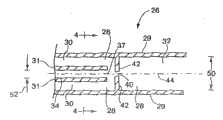
图3是本发明的微型射流器件的示意图; Fig. 3 is the schematic diagram of micro-fluidic device of the present invention;
图4是通过图3的线4-4截取的示意截面图; Figure 4 is a schematic cross-sectional view taken through line 4-4 of Figure 3;
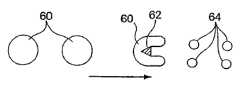
图5举例说明依照本发明分散的微滴经由障碍被进一步分散的原则; Fig. 5 illustrates according to the principle that the dispersed droplet of the present invention is further dispersed through obstacles;
图6举例说明包括经由障碍分散或缺乏这种分散的五种不同的情况; Figure 6 illustrates five different situations involving dispersion via barriers or the absence of such dispersion;
图7举例说明在有借助障碍进一步分散的情况下在T-接合部形成的分散体; Figure 7 illustrates the dispersion formed at the T-junction with further dispersion by means of barriers;
图8举例说明借助T-接合部每个分支中不同的反压形成不同的T-接合部分散体; Figure 8 illustrates the formation of different T-junction dispersions by means of different back pressures in each branch of the T-junction;
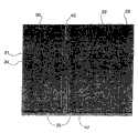
图9是在图3中示意地举例说明的本发明的微型射流安排的放大照片的影印件; Figure 9 is a photocopy of an enlarged photograph of the micro-jet arrangement of the present invention schematically illustrated in Figure 3;
图10(图像a-e)是图5的安排在使用中的放大照片的影印件; Figure 10 (images a-e) is a photocopy of an enlarged photograph of the arrangement of Figure 5 in use;
图11(图像a-e)是依照另一个实施方案图5的安排在使用中的放大照片的影印件; Figure 11 (images a-e) is a photocopy of an enlarged photograph of the arrangement of Figure 5 in use according to another embodiment;
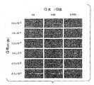
图12是图5的安排在使用中在多种流体流速和比率下的放大照片的影印件; Figure 12 is a photocopy of an enlarged photograph of the arrangement of Figure 5 in use at various fluid flow rates and ratios;
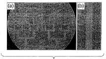
图13(区段a-e)是展示气体在液体中的分散体的显微照片的影印件;图13(区段f-i)表示在更低的流速下,被分散的流体部分将开始失去它们圆形的形状; Figure 13 (section a-e) is a photocopy of a photomicrograph showing a dispersion of gas in a liquid; Figure 13 (section f-i) shows that at lower flow rates the dispersed fluid fractions will begin to lose their circular shape shape;
图14(区段a-d)是展示在微型射流系统中借助障碍分散物种被进一步分散的分散体的显微照片的影印件; Figure 14 (sections a-d) is a photocopy of a photomicrograph showing the dispersion of the dispersed species being further dispersed by means of barriers in the microfluidic system;
图15(区段a-c)是分散物种在T-接合部被进一步分散的分散体的显微照片的影印件,其中不同的分散体是用不同的反压表示的;而 Figure 15 (sections a-c) are photocopies of photomicrographs of dispersions in which dispersed species are further dispersed at T-junctions, where different dispersions are represented by different back pressures; and
图16(区段a-b)是分散物种经由连续的T-接合部被进一步分散的分散体的显微照片的影印件(a)和在高度分散的物种方面的结果(b)。 Figure 16 (Panels a-b) are photocopies (a) of photomicrographs of dispersions in which dispersed species were further dispersed via continuous T-junctions and the results (b) for highly dispersed species. the
具体实施方式Detailed ways
下列的文件在此通过引证被全部并入本文:1996年4月30日授权给Kumar等人的美国专利第5,512,131号;1996年6月26日公开的Whitesides等人的国际专利公开WO 96/29629;2002年3月12日授权给Kim等人的美国专利第6,355,198号;和2001年11日月29公开的Anderson等人的国际专利公开WO 01/89787。本发明提供用来引起流体之间相互作用的微型射流技术,尤其是形成流体的不连续部分,例如,生产分散体和乳状液。本发明在若干方面不同于用来形成分散流体的大多数已知技术。 The following documents are hereby incorporated by reference in their entirety: U.S. Patent No. 5,512,131 issued April 30, 1996 to Kumar et al; International Patent Publication WO 96/29629 to Whitesides et al published June 26, 1996 ; U.S. Patent No. 6,355,198 issued March 12, 2002 to Kim et al; and International Patent Publication WO 01/89787 by Anderson et al published on November 29, 2001. The present invention provides microfluidics for inducing interactions between fluids, especially to form discrete portions of fluids, eg, to produce dispersions and emulsions. The present invention differs from most known techniques for forming dispersion fluids in several respects. the
本发明部分地包括对于在许多技术领域中需要改进分散体的形成和/或控制和应用改进的分散体的理解。依照本发明在分散体形成方面的改进能为了各种各样的用途在精确递送小体积流体(例如,纳升、皮升、甚至飞升或更小数量)方面找到应用。例如,一条可能的系统递送小体积流体的路径是形成尺寸受控的微滴,它们可能方便地输送特定的化学品或者可能它们自己就是小的化学反应器。因为体积为1皮升的微滴有不足10微米的半径,所以非常小的微滴的受控成形是非常重要的。指定大于一种尺寸的体积也可以借助本发明提供,例如,为了精确地控制不同的化学反应物的化学定量关系。换句话说,在需要按指定的数量将反应物递送到各种不同的位置的芯片实验室器件中,这可以通过先控制流体反应物的微滴尺寸然后控制它通过器件的递送路径得以实现。这可以依照本发明得以实现。尽管已存在对于分散体中微滴尺寸和微滴尺寸范围达到某种程度的控制,但是本发明提供用来实现对小的流体微滴的尺寸的更好的控制的技术和/或用来实现控制的改进技术。本发明提供轻松自如地可再现地控制流体微滴尺寸和尺寸范围并且把一种尺寸或尺寸范围的流体微滴转移到一个位置而把另一种尺寸或尺寸范围的微滴转移到另一个位置的能力。 The present invention consists in part of the understanding that there is a need in many technical fields for improved dispersion formation and/or control and application of improved dispersions. Improvements in dispersion formation according to the present invention can find application in the precise delivery of small volumes of fluid (eg, nanoliters, picoliters, even femtoliters or smaller quantities) for a variety of uses. For example, one possible route for the system to deliver small volumes of fluid is to form size-controlled droplets, which may conveniently deliver specific chemicals or may themselves be small chemical reactors. Because droplets with a volume of 1 picoliter have a radius of less than 10 microns, controlled formation of very small droplets is very important. Volumes specifying more than one size can also be provided by the present invention, for example, in order to precisely control the stoichiometric relationship of different chemical reactants. In other words, in a lab-on-a-chip device where specific quantities of reactants need to be delivered to various locations, this can be achieved by first controlling the droplet size of the fluid reactant and then controlling its delivery path through the device. This can be achieved according to the invention. Although some degree of control already exists over droplet size and droplet size ranges in dispersions, the present invention provides techniques for achieving better control over the size of small fluid droplets and/or for achieving Improved techniques for control. The present invention provides for the ease and reproducibility of fluid droplet size and size ranges and the transfer of fluid droplets of one size or size range to one location and another size or size range of droplets to another location Ability. the
明确地说,本发明包括与多相材料的处理相关联的器件和技术。尽管普通的技术人员将认识到依照本发明能够处理包括许多各种不同 的相的各式各样的材料之中的任何一种,不过本发明发现最经常与不相容流体的两相系统一起使用。如同在本文中使用的那样,“流体”意味着能被推动流过下面描述的器件实现本发明的优势的任何物质。原本熟悉这项技术的人将认识到流体有适合依照本发明使用的粘度,即该物质是“流体”。人们应该领会到,物质为了本发明的目的在一组条件下可能是流体,但是在其它条件下可能有太高的粘度以致无法在本发明中作为流体使用。在一种或多种材料在与本发明兼容的至少一组条件下表现为流体的场合,它们就作为可借助本发明处理的潜在材料被包括在内。 In particular, the present invention includes devices and techniques associated with the processing of multiphase materials. While those of ordinary skill will recognize that any of a wide variety of materials comprising many different phases can be processed in accordance with the present invention, the present invention finds itself most often with two-phase systems of incompatible fluids. use. As used herein, "fluid" means any substance that can be forced to flow through the devices described below to achieve the advantages of the present invention. Those originally skilled in the art will recognize that a fluid has a suitable viscosity for use in accordance with the present invention, ie, that the substance is a "fluid". It should be appreciated that a substance may be fluid under one set of conditions for the purposes of the present invention, but under other conditions may have too high a viscosity to be useful as a fluid in the present invention. Where one or more materials behave as fluids under at least one set of conditions compatible with the present invention, they are included as potential materials that can be treated by means of the present invention. the
在一组实施方案中,本发明包括在不用运动部件形成微滴的流动系统(优选微型射流系统)中分散相在分散剂之内的尺寸和尺寸分布受控的微滴的形成。换言之,在需要形成预期尺寸的微滴一个或多个位置,该器件没有相对于该器件作为一个整体运动的零部件影响微滴的形成或尺寸。例如,在形成尺寸受控的微滴的场合,它们是在没有相对于定义微滴流动通道的器件的其它部件运动的部件的情况下形成的。这可以被称为微滴尺寸的“被动控制”,或在第一组微滴被破碎成更小的微滴的场合被称为“被动破碎”。下列定义将有助于理解本发明的某些方面。本发明的某些实施方案落在其中的数组参数也包括在定义目录之内。 In one set of embodiments, the present invention comprises the formation of droplets of controlled size and size distribution of the dispersed phase within the dispersant in a fluidic system (preferably a microfluidic system) that does not use moving parts to form the droplets. In other words, there are no parts of the device that move relative to the device as a whole to affect droplet formation or size at one or more locations required to form droplets of the desired size. For example, where size-controlled droplets are formed, they are formed without moving parts relative to other parts of the device defining the droplet flow path. This may be referred to as "passive control" of droplet size, or "passive fragmentation" where the first set of droplets are broken into smaller droplets. The following definitions will assist in understanding certain aspects of the invention. Array parameters within which certain embodiments of the present invention fall are also included within the definition catalog. the
如同在本文中使用的那样,“通道”意味着在制品(基体)之中或之上能够至少部分地限制和引导体的流动而且有至少2∶1、更典型至少3∶1、5∶1或10∶1纵横比(长度与平均横截面尺寸之比)的特征。特征可能是凹槽或任何横截面形状(曲线形、正方形或矩形)的其它凹痕而且可能是被覆盖的或未被覆盖的。在它被完全覆盖的实施方案中,至少一部分通道可以有被完全封闭的横截面,或者整个通道可以除了它的入口和出口之外沿着它的整个长度被完全封闭。敞开的通道通常将包括有助于控制流体传送的特征,例如,结构特征(延长的凹痕)和/或物理或化学特性(疏水性对亲水性)或其它能够对流体施力(例如,牵制力) 的特性。通道内的流体可能部分地或完全地充满通道。在某些使用敞开的通道的情况下,流体可以利用表面张力(即,凹面或凸面的弯液面)被保留在通道之内。通道可能有任何尺寸,例如,有小于大约5或2毫米、或小于大约1毫米、或小于大约500微米、小于大约200微米、小于大约100微米、或小于大约50或25微米的垂直于流体流的最大尺寸。在某些情况下,通道的尺寸可以是这样选定的,以致流体能够自由地流过反应器。通道的尺寸也可能是这样选定的,例如,为了允许流体在通道中有某种体积流速或线性流速。当然,通道的数目和通道的形状可以借助原本熟悉这项技术的人已知的任何方法改变。在用附图举例说明的实施方案中,所有的通道都是完全封闭的。如同在本文中使用的那样,“通道”不包括在通道壁和障碍之间形成的空间。相反,如同在本文中定义的那样,障碍被理解为被包含在通道之内。较大的通道、管道及其它可以为了各种各样的。目的(例如,为了大批储存流体和把流体递送到本发明的零部件中)被用在微型射流器件中。 As used herein, "channel" means capable of at least partially restricting and directing the flow of a body in or on an article (matrix) and having at least 2:1, more typically at least 3:1, 5:1 Or a 10:1 aspect ratio (ratio of length to average cross-sectional dimension) feature. Features may be grooves or other indentations of any cross-sectional shape (curved, square or rectangular) and may be covered or uncovered. In embodiments where it is fully covered, at least a portion of the channel may have a fully closed cross-section, or the entire channel may be fully closed along its entire length except for its inlet and outlet. Open channels will typically include features that help control fluid transport, for example, structural features (elongated dimples) and/or physical or chemical properties (hydrophobic vs. traction force) characteristics. Fluid within the channel may partially or completely fill the channel. In some cases where open channels are used, fluid can be retained within the channel by surface tension (ie, a concave or convex meniscus). The channel may be of any size, for example, having a diameter perpendicular to fluid flow of less than about 5 or 2 mm, or less than about 1 mm, or less than about 500 microns, less than about 200 microns, less than about 100 microns, or less than about 50 or 25 microns the maximum size of . In some cases, the dimensions of the channels may be selected such that fluids can flow freely through the reactor. The dimensions of the channels may also be selected, for example, to allow a certain volumetric or linear flow rate of the fluid in the channels. Of course, the number of channels and the shape of the channels may be varied by any means known to those skilled in the art. In the embodiments illustrated in the figures, all channels are completely closed. As used herein, "channel" does not include the space formed between channel walls and obstacles. Rather, obstacles, as defined herein, are understood to be contained within the passage. Larger passages, pipes and others can be ordered for various. Purposes (eg, for bulk storage and delivery of fluids into components of the invention) are used in microfluidic devices. the
不同的零部件可以用不同的材料制造。例如,微型射流器件的基础部分,包括底部的通道壁和侧面的通道壁,可以用诸如硅或PDMS之类不透明材料制造,而顶部或盖子可以用诸如玻璃或透明的聚合物之类透明的材料制造以便观察和控制射流过程。零部件可以是有涂层的,以便在底部支撑材料没有精确的预期的功能性的场合将预期的化学功能性暴露在接触通道内通道壁的流体之中。例如,零部件可以是如同举例说明的那样制造的,有用另一种材料涂过的通道内通道壁。 Different parts can be made of different materials. For example, the base part of a microfluidic device, including the bottom and side channel walls, can be fabricated from an opaque material such as silicon or PDMS, while the top or lid can be made of a transparent material such as glass or a transparent polymer. Manufactured to observe and control the fluidic process. Parts may be coated to expose the intended chemical functionality to fluid contacting the channel walls within the channel where the bottom support material does not have the precise intended functionality. For example, the component could be fabricated as illustrated with the channel walls within the channels coated with another material. the
图1是用来减少流体流尺寸和作为替代形成被第二流体分开的第一流体微滴的典型的现有的“流动聚焦”技术的部分横截面的示意图。在图1的安排中,管道10有位于在内藏管道10的容器16的通道壁面上形成的小孔14的上游并且指向小孔14的出口12。第一流体18流过管道10而且在出口12离开流体10。第二流体20以比壳体16外面的压力高的压力装在壳体16的内部22之中。由于这个压差,流体20通过孔口14从壳体16中逸出,而流体18借助流体20的作用向小 孔14延伸并且通过小孔14被吸出。流体18的稳定的细液体射流24发生,而且能被破碎成不连续的区段。这种通常称之为“流动聚焦”的技术已经针对包括燃料注入、制造食品颗粒和制造药物等在内的多种用途予以描述。 Figure 1 is a schematic diagram of a partial cross-section of a typical prior art "flow focusing" technique used to reduce fluid stream size and instead form droplets of a first fluid separated by a second fluid. In the arrangement of FIG. 1 , the
图2是通过图1的线2-2截取的展示壳体16和管道10的截面图。壳体16通常被安排成完全包围着管道10,以致流体20在流体18从管道10的出口流出之时完全包围着流体18。图1和2的安排是由多个零件制成的,相对于本发明的器件结构,通常需要比较复杂的多个步骤的加工,而且在总尺寸方面通常要大得多。 FIG. 2 is a cross-sectional
现在参照图3,以微型射流系统26的形式用横截面示意地举例说明本发明的一个实施方案(虽然人们将理解没有图4的顶部外通道壁38的系统26的俯视图似乎上相似的)。虽然“顶部”和“底部”被用来定义本发明的系统的某些部分和透视图,但是人们将理解系统可以被用在不同于所描述的那些方位。作为参考,人们注意到,系统是这样设计的,以致就图3的每个方位而言流体从左到右流动都是最佳的。 Referring now to FIG. 3, one embodiment of the invention is schematically illustrated in cross-section in the form of a microfluidic system 26 (although one will appreciate that the top view of the
系统26包括一系列定义微型射流系统的各个区域的通道壁,我们将借助这些通道壁描述该系统。微型射流互连区域28借助通道壁29限定在系统中,而且包括上游部分30和在图3展示的与更远的出口下游连接的下游部分32。在图3举例说明的实施方案中,侧通道壁31所定义的对象流体通道34是在互连区域28的外边界之内提供的。对象流体通道34有在互连区域28的上游部分30和下游部分32之间的出口37。因此,该系统是为将对象流体从通道34递送到在上游部分和下游部分之间的互连区域中而安排的。 The
图4(通过图3中线4-4截取的横截图)除了在图3中展示的一些零部件-通道壁29和31之外还展示底部的通道壁36和顶部的通道壁38,它们与通道壁29和31一起定义连续区域28(在其上游部分30)和对象流体通道34。人们能见到互连区域28在上游部分30包括被对象流体通道34分开的两个分开的区段。这两个分开的区段在更远的下游 互连。 Fig. 4 (cross-section taken through line 4-4 in Fig. 3) also shows the
再一次参照图3,互连区域28包括借助从侧面的通道壁29延伸到互连区域之中的延伸段42形成的尺寸受限制的区段40。在举例说明的实施方案中,从互连区域的上游部分30流向下游部分32的流体必须通过尺寸上受限制的区段40。对象流体通道34的出口37位于尺寸受限制区段的上游。在举例说明的实施方案中,互连区域28的下游部分有与对象流体通道34的中心轴线相同的中心轴线44。换句话说,对象流体通道是为在尺寸受限制区段的上游释放对象流体而定位的并且与尺寸受限制区段成一条直线。与图3所示的安排一样,对象流体通道34将对象流体释放到互连区域28的内部。换句话说,互连区域的外边界在对象流体通道的外边界之外。在互连区域中向下游流动的流体与从对象流体通道释放的流体相遇的精确点,对象流体至少部分地被互连区域中的流体包围,但是未被互连区域中的流体完全包围。在举例说明的实施方案中,它自始至终被包围其圆周的大约50%。对象流体的圆周部分受底部的通道壁36和顶部的通道壁38制约。 Referring again to FIG. 3 , the
在举例说明的实施方案中,尺寸受限制的区段是环形孔,但是它可以采用多种形状之中的任何形状。例如,它可能是细长的、卵形的、正方形的等等。优选的是,它是以任何导致分散流体包围和压缩对象流体横截面形状的方式成形的。尺寸受限制区段在优选的实施方案中是无阀门的。换句话说,它是不能在打开状态和和关闭状态之间切换的小孔,而且其大小通常是固定的。 In the illustrated embodiment, the size-restricted section is an annular hole, but it may take any of a variety of shapes. For example, it may be elongated, oval, square, etc. Preferably, it is shaped in any manner that results in the dispersion fluid surrounding and compressing the cross-sectional shape of the subject fluid. The size-restricted section is unvalved in a preferred embodiment. In other words, it is a small hole that cannot be switched between an open state and a closed state, and its size is usually fixed. the
虽然在图3和4中未予以展示,但是在图3和4的安排中可以提供一个或多个的中间流体通道,以便提供包围着借助分散流体对对象流体的作用产生的对象流体的不连续部分的封装流体。在一个实施方案中,提供两个中间流体通道,在对象流体通道34两边一边一个,每个都有在对象流体通道的出口附近的出口。 Although not shown in Figures 3 and 4, one or more intermediate fluid passages may be provided in the arrangement of Figures 3 and 4 to provide a discontinuity surrounding the subject fluid created by the action of the dispersing fluid on the subject fluid. part of the packaging fluid. In one embodiment, two intermediate fluid channels are provided, one on either side of subject
在一些但不是全部的实施方案中,系统26的所有零部件都是微型射流的。如同在本文中使用的那样,“微型射流”指的是包括至少一 个横截面尺寸小于1毫米(mm)而且最大横截面尺寸与长度之比至少为3∶1的流体通道的器件、装置或系统,而“微型射流通道”是满足这些判据的通道。横截面尺寸垂直于流体流动方向测量的。在本发明的流体通道中大多数零部件有小于2毫米、优选小于1毫米的最大横截面尺寸。在一组实施方案中,所有的流体通道至少在一种流体被另一种流体分散的区域是微型射流通道或最大横截面尺寸不超过2毫米。在另一个实施方案中,与流体分散相关联的所有部分地靠单一零部件(例如,被蚀刻的基体或模塑成形的单元)形成的流体通道都是微型射流通道或最大尺寸为2毫米的通道。当然,较大的通道、管道等能用来大批储存流体和把流体递送给本发明的零部件。 In some, but not all embodiments, all components of
在本文中使用的“微型射流互连区域指的是器件、装置或系统中包括两个以上流体连通的微型射流通道的部分。 As used herein, "microfluidic interconnection region" refers to a part of a device, device, or system that includes more than two microfluidic channels in fluid communication.
在一组实施方案中,所有活跃的流体通道(即所有的参与流体分散的通道)的最大横截面尺寸都小于500微米、或小于200、100、50或25微米。例如,互连区域28的横截面50以及最大对象流体通道34的横截面尺寸52都可以小于这些尺寸之中的任何一个。互连区域28的上游区段30也可以用这些最大横截面边界中的任何一个来定义。器件和系统也可能包括有非微型射流部分的通道。 In one set of embodiments, all active fluidic channels (ie, all channels participating in fluid dispersion) have a largest cross-sectional dimension of less than 500 microns, or less than 200, 100, 50 or 25 microns. For example, both the
如同在本文中使用的那样,“通道”意味着在至少部分地引导流体流动的制品(基体)之中或之上的特征。该特征可能是任何横截面形状(曲线形的,正方形的或如同附图中举例说明的矩形的,等等)的凹槽而且可以是被覆盖的或未被覆盖的。在它被完全覆盖的实施方案中,通道的至少一个部分可以有被完全封闭的横截面,或者整个通道可以沿着它的整个长度除了它的入口和出口之外被完全封闭。除非另有说明,在用附图举例说明的实施方案中,所有的通道都被完全封闭。 As used herein, "channel" means a feature in or on an article (substrate) that at least partially directs fluid flow. The feature may be a groove of any cross-sectional shape (curvilinear, square or rectangular as illustrated in the figures, etc.) and may be covered or uncovered. In embodiments where it is fully covered, at least a portion of the channel may have a fully closed cross-section, or the entire channel may be fully closed along its entire length except for its inlet and outlet. Unless otherwise stated, in the embodiments illustrated in the figures, all channels are completely enclosed. the
本发明的一个方面包括简化的微型射流流体混合系统的制造和最终得到的用比典型的现有技术的系统少的零部件定义的系统。例如,在用图3和4举例说明的安排中,底部部分36以及通道壁29和31彼 此成为一个整体。如同在本文中使用的那样,“整体”意味着这些部分以这样的方式结合在一起,以致它们在不将零部件切开或破坏的情况下彼此不能分开。如同举例说明的那样,底部部分36和通道壁31和29是用一块材料形成的。在举例说明的实施方案中定义互连区域28和对象流体通道34的顶部通道壁的顶部部分38可以是用与底部通道壁36和通道壁31和29相同的材料或不同的材料形成的。在一个实施方案中,至少一些上述的零部件是透明的,以致流体流动能被观察到。例如,顶部的通道壁38可能是诸如玻璃之类透明的材料。 One aspect of the present invention includes simplified fabrication of the microfluidic fluid mixing system and the resulting system is defined with fewer parts than typical prior art systems. For example, in the arrangement illustrated with Figures 3 and 4, the
各种各样的材料和方法能用来形成系统26的零部件。在某些情况下,选定的材料可以有不同的方法。例如,本发明的零部件可以用固体材料制成,其中通道可以是借助显微机械加工、旋涂和化学蒸镀之类的薄膜沉积工艺、激光加工、光刻技术、包括湿化学或等离子体工艺在内的蚀刻法等等形成的。例如,见Angell等人在Scientific,American 248:44-55(1983)上的论述。在一个实施方案中,至少系统的某些部分(例如,底部通道壁36以及通道壁29和31)是通过在硅片上蚀刻特征用硅制成的。用硅精确而有效地制造的本发明的器件的技术是已知的。在另一个实施方案中,这个区段(或其它区段)可以是用聚合物制成的,而且可能是弹性体聚合物、或聚四氟乙烯(PTFE; 或类似的东西。 A variety of materials and methods can be used to form the components of
不同的零部件可以用不同材料制造的。例如,包括底部的通道壁36和侧面的通道壁29和34的底部部分可以是用诸如硅或PDMS之类不透明的材料制造的,而顶部部分38可以是用诸如玻璃或透明的聚合物之类适合观察和控制流动过程的透明材料制造的。零部件可以有涂层,以便将需要的化学功能性暴露在接触底部支撑材料没有精确的预期的功能性的通道内壁的流体之中。例如,零部件可以是如同举例说明的那样制造的,其中通道内壁涂上一层其它材料。 Different parts can be made of different materials. For example, the bottom portion including the
制造本发明的器件所用的材料或涂在流体通道内壁上的材料预期可从那些将不产生不利影响或不受流过器件的流体影响的材料之中 选定,例如,在有流体存在的情况下在将在器件之内使用的工作温度和压力下呈化学惰性的材料。 The materials used to make the devices of the present invention or to coat the interior walls of the fluid passages are expected to be selected from among those that will not be adversely affected or affected by fluid flowing through the device, e.g., in the presence of fluids A material that is chemically inert at the operating temperatures and pressures that will be used within the device. the
在一个实施方案中,本发明的零部件是用聚合物的和/或柔性的和/或弹性体的材料制成的,而且可以方便地用可硬化的流体制成,从而有利于借助模塑成形(例如,复制模塑、注塑、铸塑等)制造。可硬化的流体本质上可以是任何能被引发凝固或自然凝固成有能力容纳和传送打算在微型射流网络结构之中使用的流体的固体的流体。在一个实施方案中,可硬化的流体包括聚合物液体或液体聚合物的前身(即“预聚物”)。适当的聚合物液体可以包括,例如,热塑性聚合物、热固性聚合物或这样的聚合物加热到它们的熔点以上的混合物;或溶解在适当的溶剂中在除去溶剂(例如,借助蒸发)之后能形成固体聚合材料的一种或多种聚合物的溶液。这样的能从熔融状态凝固的、借助溶剂蒸发或借助催化作用凝固的聚合物材料对于熟悉这项技术的人是已知的。多种聚合物材料(其中大多数是弹性体)是适当的,而且就模具原型之一或两者由弹性体材料组成的实施方案而言对于形成模具或模具原型也是适当的。这样的聚合物的的例子的非限制性目录包括一般的硅树脂类聚合物、环氧树脂类聚合物和丙烯酸酯类聚合物。环氧树脂类聚合物是以存在通常被称为环氧基、1,2-环氧化物或环氧乙烷的三段式环醚为特色的。例如,除了基于芳香族胺,三嗪和环脂族主链的化合物之外,可以使用双酚A的二环氧甘油醚。另一个例子包括众所周知的NovolacTM聚合物。依照本发明适合使用的适当的硅树脂类弹性体的例子包括从包括诸如甲基氯硅烷、乙基氯硅烷和苯基氯硅烷之类的氯硅烷的产物母体形成的那些。 In one embodiment, the parts of the present invention are made of polymeric and/or flexible and/or elastomeric materials, and may conveniently be made of hardenable fluids, thereby facilitating Forming (eg, replication molding, injection molding, casting, etc.) manufacturing. The hardenable fluid can be essentially any fluid that can be induced to solidify or naturally solidify into a solid capable of containing and delivering the fluid intended for use within the microfluidic network structure. In one embodiment, the hardenable fluid comprises a polymer liquid or a precursor (ie, "prepolymer") of a liquid polymer. Suitable polymeric liquids may include, for example, thermoplastic polymers, thermosetting polymers, or mixtures of such polymers heated above their melting point; or dissolved in a suitable solvent capable of forming after removal of the solvent (e.g., by evaporation) A solution of one or more polymers of a solid polymeric material. Such polymeric materials which can solidify from the molten state, by solvent evaporation or by catalysis are known to those skilled in the art. A variety of polymeric materials, most of which are elastomeric, are suitable, and for embodiments where one or both of the mold prototypes consist of an elastomeric material, are also suitable for forming the mold or mold prototypes. A non-limiting list of examples of such polymers includes silicone-based polymers, epoxy-based polymers, and acrylate-based polymers in general. Epoxy polymers are characterized by the presence of a three-block cyclic ether commonly referred to as epoxy, 1,2-epoxide, or oxirane. For example, diglycidyl ethers of bisphenol A may be used in addition to compounds based on aromatic amines, triazines and cycloaliphatic backbones. Another example includes the well known Novolac™ polymers. Examples of suitable silicone-based elastomers suitable for use in accordance with the present invention include those formed from product precursors including chlorosilanes such as methylchlorosilane, ethylchlorosilane, and phenylchlorosilane.
硅树脂类聚合物在一组实施方案中是优选的,例如,硅树脂类弹性体聚二甲基硅氧烷(PDMS)。可仿效的聚二甲基硅氧烷聚合物包括Dow Chemical Co.,Midland MI在商标 
用PDMS之类的硅氧烷聚合物形成本发明的微型射流结构的另一个优势是这样的聚合物被氧化的能力,例如,通过暴露在诸如空气等离子体之类的含氧等离子体之中,以致被氧化的结构在它们的表面包含能够与其它被氧化的硅氧烷聚合物表面或各式各样其它的聚合物和非聚合物材料被氧化的表面交联的化学基团。因此,零部件可以被制造出来,然后被氧化,而且本质上被不可逆地密封到其它的硅氧烷聚合物表面或与被氧化的硅氧烷聚合物表面反应的其它基体表面上,不需要另外的粘合剂或其它密封装置。在大多数情况下,密封能通过简单地使被氧化的硅氧烷表面接触另一个表面得以完成,不需要为了形成密封施加辅助压力。换句话说,预先氧化的硅氧烷表面对适当的配合表面起接触粘合剂的作用。明确地说,除了可对它本身不可逆地密封之外,被氧化的PDMS之类被氧化的硅氧烷也能不可逆地密封到不同于它自己的一系列被氧化的材料上,包括,例如,已以与PDMS类似的方式(例如,暴露在含氧的等离子体之中)被氧化的玻璃、硅、氧化硅、石英、氮化硅、聚乙烯、聚苯乙烯、玻璃化碳黑和环氧树脂聚合物。在本发明的思路中有用的氧化和密封以及全部的成型技术是Duffy等人在通过引证被并入的“Rapid Prototyping of Microfluidic System and Polydimenthylsiloxane(微型射流系统的快速原型设计和聚二甲基硅氧烷),Analytical Chemistry,Vol.70,第474-480页(1998)中描述的。 Another advantage of forming the microfluidic structures of the present invention from silicone polymers such as PDMS is the ability of such polymers to be oxidized, for example, by exposure to oxygen-containing plasmas such as air plasmas, Such that the oxidized structures contain on their surfaces chemical groups capable of crosslinking with other oxidized silicone polymer surfaces or with the oxidized surfaces of a variety of other polymeric and non-polymeric materials. Thus, parts can be fabricated, then oxidized, and essentially irreversibly sealed to other silicone polymer surfaces or other substrate surfaces that react with the oxidized silicone polymer surface, without additional adhesive or other sealing device. In most cases, sealing can be accomplished by simply bringing the oxidized silicone surface into contact with another surface, without the need for additional pressure to be applied to form the seal. In other words, the pre-oxidized silicone surface acts as a contact adhesive to the appropriate mating surface. Specifically, in addition to being irreversibly sealed to itself, an oxidized siloxane such as oxidized PDMS can also be irreversibly sealed to a range of oxidized materials other than itself, including, for example, Glass, silicon, silicon oxide, quartz, silicon nitride, polyethylene, polystyrene, glassy carbon, and epoxy that have been oxidized in a manner similar to PDMS (e.g., by exposure to an oxygen-containing plasma) Resin polymer. Oxidation and sealing and overall molding techniques useful in the teachings of the present invention are Duffy et al. Alkanes), described in Analytical Chemistry, Vol.70, pages 474-480 (1998).
用被氧化的硅氧烷聚合物形成本发明的微型射流结构(或接触流体的内表面)的另一个优势是这些表面与典型的弹性体聚合物表面 相比(在需要亲水性的内表面的场合)能具有强得多的亲水性。因此,这样的亲水性通道表面与典型的未被氧化的弹性体聚合物或其它的憎水材料组成的结构相比能更容易用水溶液填充和润湿。因此,本发明的器件可以具有与未被氧化的弹性体聚合物相比更亲水的表面。 Another advantage of using oxidized siloxane polymers to form the microfluidic structures (or fluid-contacting interior surfaces) of the present invention is that these surfaces are compared to typical elastomeric polymer surfaces (where hydrophilicity is desired on interior surfaces). occasions) can have a much stronger hydrophilicity. Thus, such hydrophilic channel surfaces can be more easily filled and wetted with aqueous solutions than typical structures composed of unoxidized elastomeric polymers or other hydrophobic materials. Thus, the devices of the present invention may have a more hydrophilic surface than non-oxidized elastomeric polymers. the
在一个实施方案中,底部通道壁36是用不同于一个或多个通道壁29或31或顶部通道壁38或其它零部件的材料制成的。例如,底部通道壁36的内表面可以包括硅晶片或微芯片或其它基体的表面。其它的零部件可以如同前面描述的那样被密封到这样的替代基体上。在需要将硅氧烷聚合物(例如,PDMS)组成的零部件密封到不同材料的基体(底部通道壁)上的场合,优选的是基体选自被氧化的硅氧烷聚合物能够与它不可逆地密封的一组材料(例如,表面已被氧化的玻璃、硅、氧化硅、石英、氮化硅、聚乙烯、聚苯乙烯、环氧树脂聚合物和玻璃化碳黑)。作为替代,其它的密封技术也能使用,这对于熟悉这项技术的人将是明显的,包括但不限于使用分开的粘合剂、热粘接、溶剂粘接、超声波焊接及其它。 In one embodiment,
本发明为在分散流体中形成对象流体的不连续的或隔离的区域创造条件,其中这些流体非必选地被一种或多种中间流体分开。这些流体可以由熟悉这项技术的人通过考虑流体之间的关系从本质上任何流体(液体、气体等)之中选定。例如,对象流体和分散流体是这样选定的,以致它们在形成分散部分的时间范围内不能相混。在分散部分在足够长的时间周期里保持液体状态的场合,流体应该是充分不相混的。在形成分散部分之后分散部分很快地通过聚合等方式变硬的情况下,流体不需要被看作是不能相混的。原本熟悉这项技术的人能使用接触角测量结果或类似的参数选择适当的不能相混的流体,实现本发明的技术。 The present invention provides for the formation of discrete or isolated regions of subject fluids in a dispersing fluid, wherein these fluids are optionally separated by one or more intermediate fluids. These fluids can be selected from among essentially any fluid (liquid, gas, etc.) by one skilled in the art by considering the relationship between the fluids. For example, the object fluid and the dispersing fluid are selected such that they cannot be mixed within the time frame in which the dispersing portion is formed. Where the dispersed portion remains liquid for a sufficiently long period of time, the fluids should be sufficiently immiscible. In cases where the dispersed portion hardens, by polymerization or the like, shortly after forming the dispersed portion, the fluids need not be considered immiscible. One skilled in the art can use contact angle measurements or similar parameters to select appropriate immiscible fluids to implement the techniques of the present invention. the
对象流体分散体能基于本文的教导以及在流动聚焦领域中可得的教导受原本熟悉这项技术的人的控制。例如,为了实现本发明的目的选择流体可以参考Ganan-Calvo以“Generation of Steady Liquid Microthreads and Micro-Sized Monodispersed Sprays and Gas Streams”为题发表在Phys.Rev.Lett.,80:2(1998年1月12日)上的文章以及很多其它的文本。如同从下面的例子将更全面地领会到的那样,分散流体的流速控制和分散流体与对象流体的流速比能用来控制对象流体流和/或分散体尺寸,以及流体分散体中的单分散性和多分散性之比。与本文教导的流速和比率控制结合,本发明的微型射流器件允许充分改善的控制和范围。分散部分的尺寸能向下延伸到直径小于1微米。 The subject fluid dispersion can be controlled by one originally skilled in the art based on the teachings herein and those available in the field of flow focusing. For example, in order to realize the purpose of the present invention to select fluid can refer to Ganan-Calvo to be published in Phys.Rev.Lett., 80:2 (1998 1 12) and many other texts. As will be more fully appreciated from the examples below, control of the flow rate of the dispersing fluid and the ratio of the flow rates of the dispersing fluid to the subject fluid can be used to control the subject fluid flow and/or dispersion size, as well as monodispersity in the fluid dispersion. ratio of sex and polydispersity. Combined with the flow rate and ratio control taught herein, the microfluidic devices of the present invention allow substantially improved control and range. The size of the discrete portions can extend down to less than 1 micron in diameter. the
许多分散体有整体性质,例如,流变特性;分散体怎样流动,以及诸如光学性质、口感、手感之类受分散体尺寸和分散体尺寸分布影响的非必选的其它性质。诸如现有技术的流动聚焦技术之类典型的现有技术大部分普遍包括单分散系统。本发明还包括导致不连续区段的双分散和多分散分布的条件控制,这在通过改变不连续的尺寸分布等参数来影响整体性质的时候可能是有用的。 Many dispersions have bulk properties, for example, rheological properties; how the dispersion flows, and optionally other properties such as optical properties, mouthfeel, hand, etc. that are affected by the size of the dispersion and the size distribution of the dispersion. Typical prior art techniques such as prior art flow focusing techniques generally involve monodisperse systems for the most part. The present invention also includes control of conditions leading to bidisperse and polydisperse distributions of discrete segments, which may be useful when influencing bulk properties by varying parameters such as the size distribution of the discrete. the
本发明能用来形成在医学(例如,药物)、护肤产品(例如,洗剂、淋浴凝胶)、食物(例如,沙拉酱、冰激凌)、墨水微囊、油漆、微工程材料的微样板(例如,光子晶体(photonic crystals)、智能材料等)、泡沫等等之中使用的各种各样的分散流体区段或粒子。依照本发明生产的高度单分散的浓缩液晶微滴能自动组织成二维和三维的空间结构,而且这些能被用于,例如,新颖的光学器件。 The present invention can be used to form micropatterns in medicine (e.g., drugs), skin care products (e.g., lotions, shower gels), foods (e.g., salad dressings, ice cream), ink microcapsules, paints, microengineered materials ( For example, various dispersed fluid segments or particles used in photonic crystals (photonic crystals, smart materials, etc.), foams, and the like. Highly monodisperse condensed liquid crystal droplets produced according to the present invention can automatically organize into two-dimensional and three-dimensional spatial structures, and these can be used, for example, in novel optical devices. the
本发明的一个优势是增强对对象流体的不连续部分的尺寸的控制。这与许多现有技术相反,在这些现有技术中内部的流体通常被拖入尺寸小于流体被迫通过的小孔的微滴组或微滴流。在本发明中,一些实施方案包括形成平均横截面尺寸或平均直径分别不小于尺寸受限制区段的平均横截面尺寸的对象流体流和/或不连续部分。本发明包括通过控制分散流体、对象流体或两者的流速和/或控制这些流速的比例,二者择一地结合微型射流环境,来控制这些平均横截面尺寸或直径。在其它的实施方案中,对象流体流和/或不连续部分的平均横截面 尺寸或平均直径分别不小于尺寸受限制区段的平均横截面尺寸的90%,或在其它的实施方案中不小于尺寸受限制区段的平均横截面尺寸的80%、70%、60%、50%、40%或30%。这可能是有利的,因为本发明的系统能在某个流速范围之内操作并且能在达到增加流速将分别在对象流体流和/或不连续部分的平均横截面尺寸或平均直径方面引起相应的减少的临界流速之前的那些变化的流速下分别产生本质上相同的对象流体流或不连续区段的尺寸(借助尺寸受限制区段的尺寸设定的尺寸)。 One advantage of the present invention is enhanced control over the size of discrete portions of the subject fluid. This is in contrast to many prior art techniques in which the fluid inside is generally drawn into a droplet set or stream that is smaller in size than the pores through which the fluid is forced. In the present invention, some embodiments include forming subject fluid streams and/or discontinuities having an average cross-sectional dimension or average diameter, respectively, not less than the average cross-sectional dimension of the size-restricted section. The present invention includes controlling these mean cross-sectional dimensions or diameters by controlling the flow rates of the dispersing fluid, the subject fluid, or both and/or controlling the ratio of these flow rates, alternatively in conjunction with the microfluidic environment. In other embodiments, the average cross-sectional dimension or average diameter of the subject fluid flow and/or discontinuity, respectively, is not less than 90% of the average cross-sectional dimension of the size-restricted segment, or in other embodiments is not less than 80%, 70%, 60%, 50%, 40% or 30% of the average cross-sectional dimension of the size-restricted section. This may be advantageous because the system of the present invention is capable of operating within a range of flow velocities and can achieve increased flow velocities that will cause a corresponding increase in the subject fluid flow and/or the average cross-sectional dimension or average diameter of the discontinuity, respectively. Those varying flow rates preceding the reduced critical flow rate yield essentially the same subject fluid flow or size of the discontinuous section (dimensioned by the size of the size-restricted section), respectively. the
在一些实施方案中,气-液分散体可以形成从而产生泡沫。随着气体在气-液分散体中的体积百分比增加,个体气泡当它们相互挤压的时候可能失去它们球形的形状。如果受一个或多个表面限制,这些球体可能被压扁,但是当通过压缩表面观看时通常将维持圆形的形状。通常,当气泡以较高的体积百分比变成非球形或多角形的时候,分散体被称为泡沫。虽然在一些实施方案中许多因素(例如,分散体尺寸、粘度和表面张力)可能影响泡沫形成的时间,但是当气-液分散体中气体的体积百分比超过,例如,75、80、85、90或95的时候泡沫形成(非球形气泡)。 In some embodiments, a gas-liquid dispersion can be formed to generate a foam. As the volume percent of gas in the gas-liquid dispersion increases, individual gas bubbles may lose their spherical shape as they squeeze against each other. These spheres may be squashed if constrained by one or more surfaces, but will generally maintain a circular shape when viewed through the compressed surface. Generally, when the bubbles become non-spherical or polygonal at a higher volume percentage, the dispersion is called a foam. Although many factors (e.g., dispersion size, viscosity, and surface tension) may affect the time to foam formation in some embodiments, when the volume percent of gas in the gas-liquid dispersion exceeds, for example, 75, 80, 85, 90 or 95 when foam formation (non-spherical bubbles). the
下面将描述能依照本发明的某些方面被破碎成较小的微滴的最初的对象流体微滴(或分散相)的形成。人们将理解,为了形成对象流体微滴本质上可以使用任何技术,包括本文描述的那些。用来形成对象流体微滴的一种技术可以使用图1所示的器件来完成。图1是用来减少流体流尺寸和作为替代形成被第二流体分开的第一流体的微滴的典型的现有技术的“流动聚焦”技术的局部剖视示意图。这种安排在上面描述过。 The formation of droplets (or dispersed phase) of the primary subject fluid that can be broken up into smaller droplets in accordance with certain aspects of the invention is described below. It will be appreciated that essentially any technique may be used to form the subject fluid droplets, including those described herein. One technique for forming droplets of a subject fluid can be accomplished using the device shown in FIG. 1 . 1 is a schematic partial cross-sectional view of a typical prior art "flow focusing" technique used to reduce fluid stream size and instead form droplets of a first fluid separated by a second fluid. This arrangement is described above. the
用来形成对象流体微滴的另一种技术是通过使用在此描述的图3的器件。图3展示用横截面示意地举例说明的微型射流系统26(虽然人们将理解,系统26的俯视图在缺少顶部通道壁的情况下似乎是相似的)。虽然“顶部”和“底部”被用来定义本发明的系统的某些部分和 透视图,但是人们将理解这个系统可以在不同于本文描述的那些方位中使用。作为参考,人们应该注意到,系统是这样设计的,以致流体在图3的每个方位都优选从左到右流动。系统26包括定义借助它们描述系统的微型射流系统的各个区域的一系列通道壁。微型射流互连区域28在系统中是用通道壁29定义的,而且包括上游部分30和与在图3中未展示的更远的出口下游连接的下游部分32。在图3举例说明的实施方案中,用侧面的通道壁31定义的对象流体通道34是在互连区域28的外部边界之内提供的。对象流体通道34有在互连区域28的上游部分和下游部分之间的出口37。因此,系统是为了将对象流体在上游部分和下游部分之间从通道34递送到互连区域之中安排的。互连区域28包括从侧面的通道壁29延伸到互连区域之中的延伸段42形成的尺寸受限制区段40。在举例说明的实施方案中,从互连区域的上游部分30流向下游部分32的流体必须通过尺寸受限制区段40。对象流体通道34的出口37定位在尺寸受限制区段的上游。在举例说明的实施方案中,互连区域28的下游部分有与对象流体通道34的中心轴线相同的中心轴线44。换句话说,对象流体通道是为了在尺寸受限制区段的上游释放对象流体而定位的,并且与尺寸受限制区段在一条直线上。与图3所示的安排一样,对象流体通道34把对象流体释放到互连区域28的内部部分之中。换句话说,互连区域的外边界在对象流体通道的外边界之外。在互连区域中向下游流动的流体与从对象流体通道释放的流体相会的那个精确点,对象流体至少部分地被互连区域中的流体包围,但是未被互连区域中的流体完全包围。而是,在举例说明的实施方案中,它自始至终被包围其圆周的大约50%。 Another technique for forming droplets of a subject fluid is through the use of the device of FIG. 3 described herein. Figure 3 shows a
现在参照图5,适合本发明的微滴形成的一项普遍原则被示意地举例说明。在图5中,众多对象微滴60沿着箭头62指出的方向流动。微滴60是包含在分散剂(包围着微滴60,但是在图中未被明确地指出)之内的分散相微滴。使微滴60迎着障碍62流动并且撞击在障碍62上,因此微滴60在障碍的下游被破碎成较小的微滴64。使用包括本文描述的微型射流技术在内的任何适当的技术,能将微滴60引向障碍62 并使之被迫撞击障碍62,借此使之破碎成微滴64。 Referring now to FIG. 5, a general principle of droplet formation suitable for the present invention is schematically illustrated. In FIG. 5 , a plurality of
在一组实施方案中,对象流体微滴有不超过5毫米、1毫米、500微米、250微米、100微米、60微米、40微米、20微米、甚至10微米的最大横截面尺寸。在微滴本质上呈球形的场合,最大的横截面尺寸将是球体直径。最终被进一步分散的微滴64可以有与前面刚刚描述过的那些一样的最大横截面尺寸,当然,它们在横截面尺寸方面将小于微滴60。通常,被进一步分散的微滴64的最大横截面尺寸将不超过初始对象微滴60的最大横截面尺寸的80%,或不超过微滴60的最大横截面尺寸的60%、40%或20%。 In one set of embodiments, the subject fluid droplets have a maximum cross-sectional dimension of no more than 5 mm, 1 mm, 500 microns, 250 microns, 100 microns, 60 microns, 40 microns, 20 microns, or even 10 microns. Where the droplet is spherical in nature, the largest cross-sectional dimension will be the diameter of the sphere. The final further dispersed
参照图6,它举例说明用来形成各种各样的尺寸的微滴(控制微滴尺寸分布或范围)的一种安排。在图6中,众多微型射流通道66、68、70、72和74每个都运送众多对象微滴60(为了简单明了每个情况都用一个微滴表示),而且沿着箭头76的方向驱动这些微滴在包围微滴的分散剂中流动。每个通道66-74都包括不同的障碍安排。通道66没有任何障碍,微滴60在它向下游流动时不受影响。代表图5的安排的通道68在障碍62下游造成尺寸本质上一致的微滴64。通道70包括众多连续安排的障碍,一个近似在通道70的中心,而另外两个在第一个的下游,每个都近似地放置在第一个障碍和通道壁之间的中间位置。结果可能是众多尺寸本质上一致的比微滴64小的微滴76。通道72包括一个障碍,但是偏离中心。结果可能是在障碍下游形成至少两个不同微滴尺寸的不同的微滴78和80。通道74包括众多横跨通道等间隔排列的障碍,这些障碍能在其下游造成小微滴82的本质上一致的分布。通道66-74每个都能代表用来分开产生数组不同尺寸或尺寸分布的分散微滴的独立系统,或这些或其它通道的一些或全部出口能被组合起来,本质上造成任何本质上有任何微滴尺寸组合的产品。 Referring to Figure 6, it illustrates an arrangement for forming droplets of various sizes (controlling the droplet size distribution or range). In FIG. 6, a plurality of
图6的安排完全是示意性的,而且仅仅倾向于表达依照本发明能产生的各式各样的分散体。人们将理解:微滴在障碍下游特定的分布将改变,取决于诸如在分散剂之内分散相的不相混性(不相容性)(它 可以用流体接触角测量结果方面的差异或技术上已知的其它特性来表征)、流速、障碍的尺寸和形状之类的因素。虽然在图5中举例说明的是横截面形状呈三角形的障碍,而在图6中高度示意地再现了横截面本质上呈圆形的障碍,但是人们应该理解本质上任何尺寸和任何横截面形状的障碍都可能被采用(例如,正方形的、矩形的、三角形的、卵形的、圆形的)。原本熟悉这项技术的人可以选择障碍的尺寸、形状和安排以实现本质上任何最终的分散剂尺寸和部分。通道的形状和尺寸也可以有多种选择,例如,前面关于图3描述的那些。 The arrangement of Figure 6 is purely schematic and merely intended to represent the wide variety of dispersions that can be produced in accordance with the invention. It will be understood that the specific distribution of the droplets downstream of the barrier will vary depending on factors such as the immiscibility (incompatibility) of the dispersed phase within the dispersant (which can be measured using fluid contact angle differences or technical factors such as other characteristics known in the art), flow rate, size and shape of obstacles. While an obstacle having a triangular cross-sectional shape is illustrated in FIG. 5 and an essentially circular cross-sectional obstacle is highly schematically reproduced in FIG. 6, it should be understood that essentially any size and any cross-sectional shape Various obstacles may be used (eg, square, rectangular, triangular, oval, circular). One skilled in the art can choose the size, shape and arrangement of the barriers to achieve essentially any final dispersant size and fraction. The shape and size of the channel can also be selected from a variety of shapes, for example, those described above with respect to FIG. 3 . the
现在参照图7,示意地举例说明微型射流系统90,从而展示一种用来形成依照本发明能利用障碍被进一步分散的分散相微滴60的技术。系统90包括第一通道92和垂直于通道92并且以与通道92的“T”接合部为终点的第二通道94。分散剂在T-接合部上游沿着箭头96的方向在通道92内流动,而分散相在T-接合部上游沿着箭头98的方向在通道94内流动。在T-接合部,经由通道94递送的流体的分散相在经由通道92递送的分散剂内形成,该分散相被表现为流体微滴96。如同举例说明的那样,在T-接合部形成在分散剂之内的分散相是技术上已知的。与流体通道中的压力、流速等参数有关的分散剂和分散相的选择全部可以是原本熟悉这项技术的人例行公事地选定的。依照本发明,障碍98(在图7中表现为位于中心的横截面呈正方形的障碍)使微滴96在障碍下游破碎成较小的微滴100。障碍98的横向安排(用离开每个侧壁的相对距离(a)和(b)表示)允许控制最终的分散相的尺寸和尺寸分布范围,如同前面参照图6描述的那样。通道92和94本质上能采用任何几何形状。在举例说明的实施方案中,它们倾向于横截面本质上呈正方形,尺寸(c)表示小于大约1毫米或就通道提及的其它尺寸的通道侧壁之间的距离。 Referring now to FIG. 7, a
在替代安排中,图3举例说明的安排能被用在一个或多个障碍的上游,而不是如图7所示在T-接合部形成用微滴96表示的分散相。 In an alternative arrangement, the arrangement illustrated in FIG. 3 can be used upstream of one or more barriers, rather than forming a dispersed phase represented by
障碍本质上可以有任何尺寸和横截面构型。它们也可以被放置 在运送意欲被破碎成更分散的相的分散相的通道内的任何地方。为了便于制造,障碍通常将跨越通道,从其底面到顶面(在这种情况下图5、6和7是通道内的俯视图),而且其横截面的几何形状在这个跨度中通常将处处一致。 The barriers can be of essentially any size and cross-sectional configuration. They can also be placed anywhere within the channel that carries the dispersed phase that is intended to be broken up into more dispersed phases. For ease of manufacture, the barrier will generally span the channel, from its bottom to its top surface (in this case Figures 5, 6 and 7 are top views within the channel), and its cross-sectional geometry will generally be consistent throughout this span. the
现在参照图8,示意地举例说明用来进一步分散分散相的系统110。在系统110中,入口通道112将沿着箭头114的方向流动的流体递送到T-接合部116,在那里通道112垂直地邻接包括按相反方向分别从T-接合部延伸出来的区段118和120的背压控制通道。通道118和120分别接到最后结合起来将流体递送到出口通道126之中的收集通道122和124上。 Referring now to FIG. 8, a system 110 for further dispersing the dispersed phase is schematically illustrated. In system 110, inlet channel 112 delivers fluid flowing in the direction of arrow 114 to T-junction 116, where channel 112 is vertically adjoined by sections 118 and 118 that respectively extend from the T-junction in opposite directions. 120 channels of back pressure control. Channels 118 and 120 connect respectively to collection channels 122 and 124 which ultimately combine to deliver fluid into outlet channel 126 . the
通道112沿着箭头114的方向递送在某些条件(例如,原本熟悉这项技术的人已知的分散相尺寸、流速、压力等)下以任何便利的方式(例如,参照图1和3在此描述的那些)在分散剂流体相之内形成的分散流体相,以便引起分散相在T-接合部116破碎。依照本发明已经确定在每个通道118和120之中的相对流动阻力决定在这些通道之内流动的分散相微滴的相对尺寸(体积)(表现为通道118递送相对比较小的微滴128而通道120递送相对比较大的微滴130)。这些微滴在递送通道126中被合并。在以别的方式对称的器件中,逆流压力通道118和120的相对长度造成比例的反压,并且在较高的反压下(较长的通道)按比例造成尺寸比较小的微滴。因此,本发明一方面包括将第一和第二流体从递送通道递送到递送通道与第一和第二分散通道的交叉点,以及使第一流体在第一流体通道中按第一分散体尺寸分散在第二流体之内和使第一流体在第二分散通道中按不同的第二分散体尺寸分散在第二流体之内。这种安排利用在T-接合部邻近驻点的拉伸流动。 Channel 112 delivers in the direction of arrow 114 in any convenient manner (e.g., with reference to FIGS. Those described herein) form a dispersed fluid phase within the dispersant fluid phase so as to cause the dispersed phase to break up at the T-junction 116 . It has been determined in accordance with the present invention that the relative flow resistances within each of the channels 118 and 120 determine the relative size (volume) of the dispersed phase droplets flowing within those channels (expressed as channel 118 delivering relatively small droplets 128 and Channel 120 delivers relatively large droplets 130). These droplets are merged in delivery channel 126 . In an otherwise symmetric device, the relative lengths of the counterflow pressure channels 118 and 120 result in a proportional backpressure and proportionally smaller sized droplets at higher backpressures (longer channels). Accordingly, one aspect of the present invention includes delivering the first and second fluids from the delivery channel to the intersection of the delivery channel and the first and second dispersion channels, and causing the first fluid to pass through the first fluid channel in a first dispersion size Dispersing within the second fluid and dispersing the first fluid within the second fluid at different second dispersion sizes in the second dispersion channel. This arrangement utilizes extensional flow near the stagnation point at the T-junction. the
在使用T-接合部的几何学的时候,小微滴的形成通常需要在连续相中有高剪切率,因此小的微滴倾向于与分散相的小体积分数相关联。另一方面,在较低的剪切率下,分散相形成更细长的形状,后者本身意味着高分散相体积分数。 When using the T-junction geometry, the formation of small droplets generally requires high shear rates in the continuous phase, so small droplets tend to be associated with a small volume fraction of the dispersed phase. On the other hand, at lower shear rates, the dispersed phase forms a more elongated shape, which itself implies a high dispersed phase volume fraction. the
本发明的这些和其它实施方案的功能和优势将从下面的实施例得到更全面的理解。下面的实施例倾向于举例说明本发明的优势,但是不作为本发明全部范围的例证。 The functions and advantages of these and other embodiments of the invention will be more fully understood from the following examples. The following examples are intended to illustrate the advantages of the invention, but are not intended to exemplify the full scope of the invention. the
实施例 Example
下面的实施例示范利用微型射流通道几何形状在不能相混的第二分散流体的连续相中形成对象流体的微滴。就在这里描述的实验而言,流动聚焦般的几何形状已经使用软光刻加工方法按平面微通道设计被制造出来;即该实施例示范用本质上单一的步骤快速生产完整的微通道原型的能力。第一组实施例用油和水作为两种不相混的流体。用油作为连续相液体(分散流体)和用水作为分散相(对象流体),实现了各式各样的微滴成形图(不连续区段),取决于应用于每个入口液流的流速。在由此产生的不连续区段的尺寸方面的变化作为油流速Qoil和油流速与水流速之比R=Qoil/Qwater的函数被确定下来。观察到的微滴在直径方面相差三十倍,最小的微滴在数百纳米的范围内。 The following examples demonstrate the use of microfluidic channel geometry to form droplets of a subject fluid in a continuous phase of an immiscible second dispersed fluid. For the experiments described here, flow focus-like geometries have been fabricated as planar microchannel designs using soft lithographic processing methods; i.e., this example demonstrates the ability to rapidly produce complete microchannel prototypes in essentially a single step ability. A first set of embodiments uses oil and water as the two immiscible fluids. Using oil as the continuous phase liquid (dispersion fluid) and water as the dispersed phase (subject fluid), a wide variety of droplet formation patterns (discontinuous segments) were achieved, depending on the flow rate applied to each inlet stream. The change in the size of the resulting discontinuous section is determined as a function of the oil flow rate Qoil and the ratio of the oil flow rate to the water flow rate R=Qoil /Qwater . The observed droplets varied by a factor of thirty in diameter, with the smallest droplets in the range of hundreds of nanometers.
图9是依照本发明制作的用图3和4示意地举例说明的器件的放大照片(1O×)的影印件。水作为对象流体流过对象流体通道34,而油作为不相混的分散流体在包围对象流体通道的互连区段中向下游流动。然后,这两个液体相被迫流过位于对象流体通道的出口下游并且与对象流体通道的出口在一条直线上呈小孔形式的尺寸上受限制的区域40。分散流体(油)施加压力和粘性应力,强迫对象流体变成狭窄的细丝,然后在尺寸受限制区段的内部或恰好在其下游碎裂。Span80表面活性剂溶解在油相中以维持微滴抗聚结的稳定性。图10-12是在该器件中借助与对象流体66接触并且被迫通过尺寸受限制区域40的分散流体68的作用在对象流体66中形成不连续区段62的放大照片(放大20×)的影印件。如同人们见到的那样,能够提供不连续部分62的宽广的尺寸范围。例如,在图11(e)中,就这项讨论的目的而言,被明确地标注为70和72的不连续部分62表明每个不连续部分的最大横截面尺寸之比大约为5∶1。 Figure 9 is a photocopy of an enlarged photograph (1Ox) of the device schematically illustrated in Figures 3 and 4 made in accordance with the present invention. Water flows through the
图9(和图10-13)所示的微型射流器件是使用Duffy等人描述的软光刻技术用PDMS制造的,见前面的参考文献。名义上,互连区域的最大通道宽度50(参照示意图3)是1毫米,而对象流体通道34的宽度是200微米。从对象流体通道的出口36到尺寸受限制区域40的距离Hfocus是200微米,尺寸受限制部分的直径在两个不同的实验中是50微米和100微米。器件内壁的厚度是适合维持制作通道壁的PDMS和玻璃顶部通道壁38的100微米。通道的深度(通道壁29和31的高度)是100微米。在使用中实际尺寸略有变化,因为硅油引起PDMS溶胀。这些数值是用显微镜确定的。 The microfluidic devices shown in Figure 9 (and Figures 10-13) were fabricated in PDMS using the soft lithography technique described by Duffy et al., see supra ref. Nominally, the maximum channel width 50 (cf. schematic 3) of the interconnection region is 1 millimeter, while the width of the
所用的流体是蒸馏水(对象流体)和硅油(分散流体;Silicone Oil AS,Fluka)。制造商报告的硅油粘度是6mPa·sec。硅油包含0.67wt%Span80表面活性剂(Sorbitan monooleate,Aldrich)。表面活性剂溶液是这样制备的,即将表面活性剂和硅油机械混合大约30分钟,然后过滤,以便消除粒料和防止微通道堵塞。 The fluids used were distilled water (subject fluid) and silicone oil (dispersion fluid; Silicone Oil AS, Fluka). The manufacturer's reported viscosity of the silicone oil is 6 mPa·sec. The silicone oil contained 0.67
流体是通过软管(Clay Adams Intramedic PE60聚乙烯管)引进微通道的,而流速是对每种流体使用分开的注射泵(Braintree Scientific BS8000注射泵)控制的。在这个验证本发明的实施方案中,分散流体(油)的流速Qo总是大于对象流体(水)的流速Qi。三种不同的流速比被选定,Qo/Qi=4、40和400,给定的油流速在两种油入口流中对应于总流速。就每个Qo/Qi而言,跨越两个数量级以上的油流速被选定(4.2×10-5ml/sec≤Qo≤8.3×10-3ml/sec)。在Qo和Qi的每个数值,在小孔内部和恰好在小孔下游的微滴形成是使用倒装显微镜(Model DM IRB,Leica Microsystems)和高速照相机(Phantom V5.0,Photo-Sonics,Inc.;达到6000帧/秒)观察的。图像处理被用来测量作为等价球体直径报告的微滴尺寸。 Fluids were introduced into the microchannels through flexible tubing (Clay Adams Intramedic PE60 polyethylene tubing), and flow rates were controlled using separate syringe pumps for each fluid (Braintree Scientific BS8000 syringe pumps). In this embodiment demonstrating the invention, the flow rate Qo of the dispersing fluid (oil) is always greater than the flow rate Qi of the object fluid (water). Three different flow rate ratios were selected, Qo /Qi =4, 40 and 400, with a given oil flow rate corresponding to the total flow rate in the two oil inlet streams. For each Qo /Qi , an oil flow rate spanning over two orders of magnitude was chosen (4.2×10⁻⁵ ml/sec≦Qo ≦8.3×10⁻³ ml/sec). At each value of Qo and Qi , droplet formation inside and just downstream of the aperture was measured using an inverted microscope (Model DM IRB, Leica Microsystems) and a high-speed camera (Phantom V5.0, Photo-Sonics , Inc.; up to 6000 frames/sec) observed. Image processing was used to measure droplet size reported as equivalent spherical diameter.
图10(图像a-e)是在使用中图9的器件的20×放大照片的影印件。发生在尺寸受限制区域(小孔)内部的微滴破碎序列的实验图像被展示出来。形成尺寸一致的微滴,没有看得见的卫星,发生在小孔内部的 破碎。在图像之间的时间间隔是1000微秒。Qo=8.3×10⁻⁵ml/sec而Qo/Qi=4。 Figures 10 (images ae) are photocopies of photographs at 20X magnification of the device of Figure 9 in use. Experimental images of droplet breakup sequences occurring inside size-restricted regions (pores) are shown. Uniformly sized droplets are formed, with no visible satellites, and fragmentation occurs inside the pores. The time interval between images is 1000 microseconds. Qo =8.3×10⁻⁵ ml/sec and Qo /Qi =4.
图11(图像a-e)是图9的器件在不同条件下的使用中的20×放大照片的影印件。小卫星(不连续区域)陪伴着每个大的微滴(不连续区域);在小孔内部的两个对应的位置发生破碎。在图像之间的时间间隔是166微秒;Qo=4.2×10⁻⁴ml/sec,而Qo/Qi=40。 Figures 11 (images ae) are photocopies of 2Ox magnified photographs of the device of Figure 9 in use under different conditions. A small satellite (discontinuity) accompanies each large droplet (discontinuity); fragmentation occurs at two corresponding locations inside the pore. The time interval between images is 166 microseconds; Qo =4.2 x 10⁻⁴ ml/sec, and Qo /Qi =40.
图12是图9的安排在多种流体流速和流速比的使用中的放大照片的影印件。每幅图像表现不连续区域(微滴)的尺寸和在指定的Qo(行)和Qo/Qi(列)数值下形成的图案。放大倍率是20×。 Figure 12 is a photocopy of an enlarged photograph of the arrangement of Figure 9 in use at various fluid flow rates and flow ratios. Each image represents the size of the discrete regions (droplets) and patterns formed at the specified values of Qo (rows) and Qo /Qi (columns). The magnification is 2Ox.
图13提供一系列展示气泡在液体中形成的显微照片。气体分散体是使用与图3所展示的类似的微型射流聚焦器件制作的。对象流体是氮气,而分散流体是水。对象流体通道有200微米的宽度,而两个分散流体通道每个都有250微米的宽度。压缩区域是宽度为30微米的环形小孔。出口通道的宽度是750微米。馈送到对象流体通道的氮气压力是4psi。水分散相的流速阶梯式地从4毫升/小时向下变化到0.01毫升/小时。如图13(a)所示,在较高的分散流体流速(4毫升/小时)下,在流出的流体中气体的体积分数很小,而且气泡是不规则的。当分散流体的流速减少到1.8毫升/小时(图13(b))的时候,清楚的泡沫是看得见的但是仍然不够规则。当分散流体的流速减少到0.7毫升/小时(图13(c))的时候,见到较大的氮气体积分数和增加的有序程度。这种趋势在流速分别为0.5和0.1毫升/小时的情况下继续,图13(d)和(e)。在更低的流速下,如图13(f)-(i)所示,被分散的流体部分(氮气)将开始失去它们圆形的形状。我们认为,当气泡开始如图13(h)和(i)所示呈现非圆形的多角形形状时候,分散体将形成泡沫。我们相信,一旦气体在分散体中的体积分数变成大于大约90%,这些非圆形的形状容易发生。这些显微照片证明本发明以高体积分数在液体中形成有序相的能力。 Figure 13 provides a series of photomicrographs showing the formation of gas bubbles in a liquid. The gas dispersion was fabricated using a microfluidic focusing device similar to that shown in Figure 3. The object fluid is nitrogen, and the dispersion fluid is water. The subject fluid channel has a width of 200 microns, while the two dispersion fluid channels each have a width of 250 microns. The compression zone is an annular orifice with a width of 30 microns. The width of the exit channel is 750 microns. The nitrogen pressure fed to the subject fluid channels was 4 psi. The flow rate of the aqueous dispersed phase was varied stepwise from 4 ml/hr down to 0.01 ml/hr. As shown in Fig. 13(a), at a higher dispersion fluid flow rate (4 ml/h), the volume fraction of gas in the outflow fluid is small, and the bubbles are irregular. When the flow rate of the dispersion fluid was reduced to 1.8 ml/h (Fig. 13(b)), clear foam was visible but still irregular. When the flow rate of the dispersion fluid was reduced to 0.7 ml/hr (Fig. 13(c)), a larger nitrogen gas fraction and an increased degree of order were seen. This trend continued at flow rates of 0.5 and 0.1 mL/h, respectively, Fig. 13(d) and (e). At lower flow rates, the dispersed fluid fractions (nitrogen) will start to lose their circular shape as shown in Figure 13(f)-(i). We believe that the dispersion will foam when the bubbles start to take on non-circular polygonal shapes as shown in Figure 13(h) and (i). We believe that these non-circular shapes tend to occur once the volume fraction of gas in the dispersion becomes greater than about 90%. These micrographs demonstrate the ability of the present invention to form ordered phases in liquids at high volume fractions. the
为了进一步分散在不相混的流体中形成分散体的各个流体部分,制作了另一种器件。一系列的微通道使用已知的软光刻制造技术 (例如,参阅通过引证并入的Xia等人1998年发表在Angew.Chem.,Int.Edmund.Engl.,Vol.37,p.550上的文章;前面引证过的WO96/29629)已经用聚二甲基硅氧烷(PDMS)制造出来。对于在此描述的每个实施例,最初的微滴形成发生在T-接合部,而选择流速是为了维持几乎一致的微滴尺寸。通道高度是30微米,而在首先形成微滴的T-接合部,通道宽度也是30微米。在用障碍帮助破碎的情况下,障碍有60微米宽的正方形横截面,而且通道宽度从120微米变化到240微米,取决于障碍在通道内的安排(图7所示的(a)与(b)的相对比例)。选择蒸馏水形成分散相,用十六烷(剪切粘度等于0.08g/cm.sec)作为连续相。2.0wt%Span80表面活性剂被添加到油相中以协助微滴形成。使用单独的注射泵控制两相的流速。 To further disperse the individual fluid fractions forming dispersions in immiscible fluids, another device was fabricated. A series of microchannels were fabricated using known soft lithography techniques (see, for example, Xia et al. 1998 in Angew.Chem., Int.Edmund.Engl., Vol.37, p.550, incorporated by reference article; previously cited WO 96/29629) has been produced using polydimethylsiloxane (PDMS). For each of the examples described here, initial droplet formation occurred at the T-junction, and the flow rate was chosen to maintain a nearly uniform droplet size. The channel height is 30 microns, and at the T-junction where the droplet first forms, the channel width is also 30 microns. In the case of barrier-assisted fragmentation, the barrier has a
图14(a)展示一列尺寸与通道相当的微滴流过放在通道中央的障碍。微滴当它们在障碍周围的缝隙中流动的时候变形并且恰好在障碍的下游破碎成被进一步分散的微滴。图14(b)和(c)举例说明改变障碍的不对称位置允许控制被进一步分散的微滴的相对尺寸。除此之外,分散微滴的封填构型的变化可以发生在障碍下游。图14(d)举例说明当微滴的双层结构遇到偏离中央放置的障碍的时候,器件可以是这样安排的,以致只有一层中的微滴被进一步分散,因此结果是三种不同尺寸的微滴的规则序列。请注意:为了发生这种被动的微滴破碎路径,分散相的体积分数应该比较大,以致微滴不得不围绕着障碍变形,而不是仅仅通过狭窄的缝隙。 Figure 14(a) shows a column of droplets of comparable size to the channel flowing through an obstacle placed in the center of the channel. The droplets deform as they flow in the gaps around the barrier and break up into further dispersed droplets just downstream of the barrier. Figures 14(b) and (c) illustrate that varying the asymmetric position of the barrier allows control of the relative sizes of the further dispersed droplets. In addition, changes in the packing configuration of the dispersed droplets can occur downstream of the barrier. Figure 14(d) illustrates that when the double-layer structure of droplets encounters an obstacle placed off-centre, the device can be arranged so that only the droplets in one layer are further dispersed, thus resulting in three different sized A regular sequence of droplets. Note: For this passive droplet breakup path to occur, the volume fraction of the dispersed phase should be so large that the droplets have to deform around obstacles rather than just passing through narrow gaps. the
在图14(a-d)的每张图中,障碍是60微米截面的正方形。在(a)中,障碍放在通道的中心,以致比率(a)∶(b)是1∶1。在(b)中,通道宽度是150微米,而比率(a)∶(b)是1∶2。在(c)中,通道宽度是240微米,而比率(a)∶(b)是1∶5。在(d)中,当双层图案遇到偏离中心的障碍时,每隔一个微滴被进一步分散。 In each of Figures 14(a-d), the barriers are squares of 60 micron cross-section. In (a), the obstacle is placed in the center of the passage, so that the ratio (a):(b) is 1:1. In (b), the channel width is 150 microns, and the ratio (a):(b) is 1:2. In (c), the channel width is 240 microns, and the ratio (a):(b) is 1:5. In (d), every other droplet is further dispersed when the bilayer pattern encounters an off-center obstacle. the
图15举例说明分散系统借助使它在T-接合部的邻近区域经受外延流动进一步分散。就临界值以下的流速而言,个别微滴不破碎, 而是流进每个侧面的通道。对于任何给定的通道宽度与微滴直径之比,都存在一个临界流速,高于该流速,微滴破碎,如图15(a)所示,每个微滴破碎成两个尺寸相等的被进一步分散的微滴。被进一步分散的微滴的相对尺寸可以受侧面通道的流阻控制,后者本身是它们的长度和横截面的函数。图15(b)和(c)展示一些设计,其中侧面通道有递增地偏离1∶1的长度比。就层流通道而言,流动阻力与通道长度成正比。因为流动阻力设定相对的体积流速和侧面通道,所以微滴体积也随着长度比改变。不仅流动阻力能受流动通道的相对长度控制,而且压力驱动的阀门也能被使用。 Figure 15 illustrates that the dispersed system is further dispersed by subjecting it to epitaxial flow in the vicinity of the T-junction. For flow rates below the critical value, individual droplets are not broken up but flow into each side channel. For any given ratio of channel width to droplet diameter, there exists a critical flow velocity above which the droplet breaks up, as shown in Figure 15(a), where each droplet breaks into two equal-sized further dispersed droplets. The relative size of the further dispersed droplets can be controlled by the flow resistance of the side channels, which is itself a function of their length and cross-section. Figures 15(b) and (c) show designs in which the side channels have length ratios that deviate incrementally from 1:1. For laminar flow channels, the resistance to flow is proportional to the length of the channel. Since the flow resistance sets the relative volumetric flow rates and side channels, the droplet volume also changes with the length ratio. Not only can flow resistance be controlled by the relative lengths of the flow channels, but pressure-actuated valves can also be used. the
图16展示大段的分散相借助几何学上居中的T-接合部破碎成尺寸与通道横截面相当的进一步分散的更小的微滴的后续应用。具体地说,在单一的入口(区段(a)的顶端),在分散剂之内提供大量的分散相。分散相与分散剂之比是大的,至少为4∶1。在第一个T-接合部,分散相被破碎成体积大约为通过最初的入口递送的那些分散相的一半的片段。第一个T-接合部的每个出口作为另一个T-接合部的入口,通过两个以上T-接合部,最终获得的八个出口再次结合成把高度分散的微滴容纳在分散剂之内的单一的收集通道或产品通道(图16(b))。 Figure 16 shows the subsequent application of a large segment of the dispersed phase broken up by a geometrically centered T-junction into further dispersed smaller droplets of a size comparable to the channel cross-section. Specifically, at a single inlet (top of section (a)), a bulk dispersed phase is provided within the dispersant. The ratio of dispersed phase to dispersant is large, at least 4:1. At the first T-junction, the dispersed phase is broken into fragments approximately half the volume of those delivered through the initial inlet. Each outlet of the first T-junction acts as an inlet for another T-junction, and through more than two T-junctions, the resulting eight outlets are combined again to hold highly dispersed droplets between the dispersants. within a single collection or product channel (Fig. 16(b)). the
原本熟悉这项技术的人将认识到本文未展示或描述的辅助零部件在实现本发明方面是有用的。例如,各种不同的流体源、用来控制递送到本文展示的通道的这些流体的压力和/或流速的装置等等。原本熟悉这项技术的人将容易想象到用来实现本文所描述的功能和/或获得本文所描述的结果或优势的多种其它的装置和结构,而每种这样的变化或修正都被认为是在本发明范围之内。更一般地说,熟悉这项技术的人将领会到本文描述的所有的参数、尺寸、材料和构型是可仿效的,而实际的参数、尺寸、材料和构型将取决于使用本发明的教导的特定应用。熟悉这项技术的人将认识到或使用不多的例行实验就能够确定许多在此描述本发明的特定实施方案的等价方案。所以,人们将会理解上述的实施方案仅仅是作为实施例提交的,本发明可以在权利 要求书及其等价文件的范围内以不同于本文明确描述的方式的其它方式实践。本发明指向在此描述的每个独立的特征、系统、材料和/或方法。此外,如果这样的特征、系统、材料和/或方法不是互相矛盾的,两个或多个这样的特征、系统、材料和/或方法的任何组合就被包括在本发明范围之内。 Those of ordinary skill in the art will recognize ancillary components not shown or described herein to be useful in practicing the invention. For example, various sources of fluids, devices to control the pressure and/or flow rate of these fluids delivered to the channels presented herein, and the like. Those originally skilled in the art will readily imagine numerous other means and structures for performing the functions described herein and/or obtaining the results or advantages described herein, and each such variation or modification is considered to be are within the scope of the present invention. More generally, those skilled in the art will appreciate that all parameters, dimensions, materials and configurations described herein are exemplary and that actual parameters, dimensions, materials and configurations will depend on the specific application of the teaching. Those skilled in the art will recognize, or be able to ascertain using little routine experimentation, many equivalents to the specific embodiments of the invention described herein. It is therefore to be understood that the embodiments described above are presented as examples only, and that the invention may be practiced otherwise than as expressly described herein, within the scope of the claims and their equivalents. The present invention is directed to each individual feature, system, material and/or method described herein. Furthermore, any combination of two or more such features, systems, materials and/or methods is encompassed within the scope of the present invention if such features, systems, materials and/or methods are not mutually inconsistent. the
在权项(以及在上面的说明书)中,所有的过渡短语,例如“组成”、“包括”、“运送”、“有”、“包含”、“涉及”“由...组成”、“由...制成”、“由...形成”之类将被理解为无限制的,即意味着包括但不限于。只有过渡短语“由...组成”和“本质上由...组成”应该如同在United State Patent Office Manual of Patent Examining Procedures,section2111.03(美国专利局专利审查程序手册,第2111.03节)中陈述的那样分别是限定的或半限定的。 In the claims (and in the description above), all transitional phrases such as "consists of", "comprises", "conveys", "has", "comprises", "relates to", "consists of", " Made of", "formed of" and the like are to be read without limitation, meaning including but not limited to. Only the transitional phrases "consisting of" and "consisting essentially of" should be as in the United State Patent Office Manual of Patent Examining Procedures, section 2111.03 (United States Patent Office Manual of Patent Examining Procedures, Section 2111.03) Respectively defined or semi-defined as stated. the
Claims (21)
Applications Claiming Priority (4)
| Application Number | Priority Date | Filing Date | Title |
|---|---|---|---|
| US39219502P | 2002-06-28 | 2002-06-28 | |
| US60/392,195 | 2002-06-28 | ||
| US42404202P | 2002-11-05 | 2002-11-05 | |
| US60/424,042 | 2002-11-05 |
Related Parent Applications (1)
| Application Number | Title | Priority Date | Filing Date |
|---|---|---|---|
| CN03820494.0ADivisionCN1678397B (en) | 2002-06-28 | 2003-06-30 | Method and device for fluid dispersion |
Publications (1)
| Publication Number | Publication Date |
|---|---|
| CN102059162Atrue CN102059162A (en) | 2011-05-18 |
Family
ID=30003231
Family Applications (2)
| Application Number | Title | Priority Date | Filing Date |
|---|---|---|---|
| CN03820494.0AExpired - LifetimeCN1678397B (en) | 2002-06-28 | 2003-06-30 | Method and device for fluid dispersion |
| CN2010105999339APendingCN102059162A (en) | 2002-06-28 | 2003-06-30 | Microfluidic device |
Family Applications Before (1)
| Application Number | Title | Priority Date | Filing Date |
|---|---|---|---|
| CN03820494.0AExpired - LifetimeCN1678397B (en) | 2002-06-28 | 2003-06-30 | Method and device for fluid dispersion |
Country Status (7)
| Country | Link |
|---|---|
| US (3) | US7708949B2 (en) |
| EP (2) | EP1515803A2 (en) |
| JP (2) | JP2006507921A (en) |
| CN (2) | CN1678397B (en) |
| AU (1) | AU2003253751B2 (en) |
| CA (1) | CA2491564C (en) |
| WO (1) | WO2004002627A2 (en) |
Cited By (8)
| Publication number | Priority date | Publication date | Assignee | Title |
|---|---|---|---|---|
| CN103285946A (en)* | 2013-05-27 | 2013-09-11 | 苏州扬清芯片科技有限公司 | Biochip and control method thereof |
| CN103285947A (en)* | 2013-05-27 | 2013-09-11 | 苏州扬清芯片科技有限公司 | Droplet micro-fluidic chip and operation method thereof |
| CN103958050A (en)* | 2011-09-28 | 2014-07-30 | 哈佛学院院长等 | Systems and methods for droplet generation and/or fluid manipulation |
| CN105050718A (en)* | 2013-03-06 | 2015-11-11 | 哈佛学院院长及董事 | Apparatus and method for forming relatively monodisperse droplets |
| CN105344389A (en)* | 2008-05-16 | 2016-02-24 | 哈佛大学 | Microfluidic system, method, and apparatus |
| CN107414080A (en)* | 2016-05-23 | 2017-12-01 | 中国科学院理化技术研究所 | Liquid metal 3D prints shower nozzle device and is equipped with device's 3D printer |
| CN107530651A (en)* | 2015-01-22 | 2018-01-02 | 泰德微流体有限公司 | System and method for controlled manufacture single dispersing microbubble |
| CN114643088A (en)* | 2022-03-14 | 2022-06-21 | 常熟理工学院 | Micro-droplet generation chip based on Karman vortex street |
Families Citing this family (460)
| Publication number | Priority date | Publication date | Assignee | Title |
|---|---|---|---|---|
| JP2006507921A (en) | 2002-06-28 | 2006-03-09 | プレジデント・アンド・フェロウズ・オブ・ハーバード・カレッジ | Method and apparatus for fluid dispersion |
| WO2004071638A2 (en) | 2003-02-11 | 2004-08-26 | Regents Of The University Of California, The | Microfluidic devices and method for controlled viscous shearing and formation of amphiphilic vesicles |
| US20100022414A1 (en) | 2008-07-18 | 2010-01-28 | Raindance Technologies, Inc. | Droplet Libraries |
| GB0307403D0 (en) | 2003-03-31 | 2003-05-07 | Medical Res Council | Selection by compartmentalised screening |
| GB0307428D0 (en) | 2003-03-31 | 2003-05-07 | Medical Res Council | Compartmentalised combinatorial chemistry |
| US20060078893A1 (en) | 2004-10-12 | 2006-04-13 | Medical Research Council | Compartmentalised combinatorial chemistry by microfluidic control |
| WO2004091763A2 (en) | 2003-04-10 | 2004-10-28 | President And Fellows Of Harvard College | Formation and control of fluidic species |
| BRPI0414004A (en) | 2003-08-27 | 2006-10-24 | Harvard College | electronic control of fluidic species |
| US20050221339A1 (en) | 2004-03-31 | 2005-10-06 | Medical Research Council Harvard University | Compartmentalised screening by microfluidic control |
| EP1742979A4 (en)* | 2004-04-23 | 2008-05-21 | Eugenia Kumacheva | Method of producing polymeric particles with selected size, shape, morphology and composition |
| NL1026261C2 (en) | 2004-05-25 | 2005-11-28 | Nanomi B V | Spraying device with a nozzle plate provided with structures for promoting self-breakup, a nozzle plate, and methods for manufacturing and using such a nozzle plate. |
| GB0502398D0 (en)* | 2005-02-04 | 2005-03-16 | Q Chip Ltd | Device and method for producing spherical segmented flow |
| US7655470B2 (en) | 2004-10-29 | 2010-02-02 | University Of Chicago | Method for manipulating a plurality of plugs and performing reactions therein in microfluidic systems |
| US9477233B2 (en) | 2004-07-02 | 2016-10-25 | The University Of Chicago | Microfluidic system with a plurality of sequential T-junctions for performing reactions in microdroplets |
| US7968287B2 (en) | 2004-10-08 | 2011-06-28 | Medical Research Council Harvard University | In vitro evolution in microfluidic systems |
| EP1839760A1 (en)* | 2005-01-17 | 2007-10-03 | Universidad de Sevilla | Method and device for the micromixing of fluids using a reflux cell |
| WO2006078841A1 (en)* | 2005-01-21 | 2006-07-27 | President And Fellows Of Harvard College | Systems and methods for forming fluidic droplets encapsulated in particles such as colloidal particles |
| KR101198038B1 (en) | 2005-01-28 | 2012-11-06 | 듀크 유니버서티 | Apparatuses and methods for manipulating droplets on a printed circuit board |
| US9039273B2 (en) | 2005-03-04 | 2015-05-26 | President And Fellows Of Harvard College | Method and apparatus for forming multiple emulsions |
| US20070054119A1 (en)* | 2005-03-04 | 2007-03-08 | Piotr Garstecki | Systems and methods of forming particles |
| JP2006289250A (en)* | 2005-04-08 | 2006-10-26 | Kao Corp | Micromixer and fluid mixing method using the same |
| US20060280029A1 (en)* | 2005-06-13 | 2006-12-14 | President And Fellows Of Harvard College | Microfluidic mixer |
| US20070141593A1 (en)* | 2005-08-22 | 2007-06-21 | Lee Linda G | Apparatus, system, and method using immiscible-fluid-discrete-volumes |
| US7709544B2 (en)* | 2005-10-25 | 2010-05-04 | Massachusetts Institute Of Technology | Microstructure synthesis by flow lithography and polymerization |
| JP4954216B2 (en)* | 2005-10-25 | 2012-06-13 | マサチューセッツ インスティテュート オブ テクノロジー | Synthesis method of polymer microstructures by flow lithography and polymerization |
| GB2433448B (en) | 2005-12-20 | 2011-03-02 | Q Chip Ltd | Method for the control of chemical processes |
| US20100137163A1 (en) | 2006-01-11 | 2010-06-03 | Link Darren R | Microfluidic Devices and Methods of Use in The Formation and Control of Nanoreactors |
| JP4713397B2 (en) | 2006-01-18 | 2011-06-29 | 株式会社リコー | Microchannel structure and microdroplet generation system |
| WO2007089541A2 (en)* | 2006-01-27 | 2007-08-09 | President And Fellows Of Harvard College | Fluidic droplet coalescence |
| WO2007102785A1 (en)* | 2006-03-09 | 2007-09-13 | Agency For Science, Technology And Research | Apparatus for performing a reaction in a droplet and method of using the same |
| EP2007435B1 (en)* | 2006-03-31 | 2019-12-18 | Massachusetts Institute Of Technology | System for targeted delivery of therapeutic agents |
| US20140193807A1 (en) | 2006-04-18 | 2014-07-10 | Advanced Liquid Logic, Inc. | Bead manipulation techniques |
| US9476856B2 (en) | 2006-04-13 | 2016-10-25 | Advanced Liquid Logic, Inc. | Droplet-based affinity assays |
| US7901947B2 (en) | 2006-04-18 | 2011-03-08 | Advanced Liquid Logic, Inc. | Droplet-based particle sorting |
| US7439014B2 (en) | 2006-04-18 | 2008-10-21 | Advanced Liquid Logic, Inc. | Droplet-based surface modification and washing |
| US10078078B2 (en) | 2006-04-18 | 2018-09-18 | Advanced Liquid Logic, Inc. | Bead incubation and washing on a droplet actuator |
| US8637324B2 (en) | 2006-04-18 | 2014-01-28 | Advanced Liquid Logic, Inc. | Bead incubation and washing on a droplet actuator |
| US8980198B2 (en)* | 2006-04-18 | 2015-03-17 | Advanced Liquid Logic, Inc. | Filler fluids for droplet operations |
| US8809068B2 (en) | 2006-04-18 | 2014-08-19 | Advanced Liquid Logic, Inc. | Manipulation of beads in droplets and methods for manipulating droplets |
| WO2007133590A2 (en)* | 2006-05-08 | 2007-11-22 | Auburn University | Systems for and methods of characterizing reactions |
| WO2009111769A2 (en) | 2008-03-07 | 2009-09-11 | Advanced Liquid Logic, Inc. | Reagent and sample preparation and loading on a fluidic device |
| US9562837B2 (en) | 2006-05-11 | 2017-02-07 | Raindance Technologies, Inc. | Systems for handling microfludic droplets |
| ATE540750T1 (en) | 2006-05-11 | 2012-01-15 | Raindance Technologies Inc | MICROFLUIDIC DEVICE AND METHOD |
| KR100848559B1 (en)* | 2006-06-29 | 2008-07-25 | 엘지디스플레이 주식회사 | Soft Mold Manufacturing Method and Pattern Forming Method Using the Same |
| WO2008017031A2 (en)* | 2006-08-02 | 2008-02-07 | The Regents Of The University Of California | Microfluidic production of monodispersed submicron emulsion through filtration and sorting of satellite drops |
| EP3536396B1 (en) | 2006-08-07 | 2022-03-30 | The President and Fellows of Harvard College | Fluorocarbon emulsion stabilizing surfactants |
| WO2008027558A2 (en) | 2006-08-31 | 2008-03-06 | Codon Devices, Inc. | Iterative nucleic acid assembly using activation of vector-encoded traits |
| KR101556798B1 (en) | 2006-10-05 | 2015-10-01 | 메사츄세츠 인스티튜트 어브 테크놀로지 | Multifunctional Encoded Particles for High-Throughput Analysis |
| US9874501B2 (en) | 2006-11-24 | 2018-01-23 | Curiox Biosystems Pte Ltd. | Use of chemically patterned substrate for liquid handling, chemical and biological reactions |
| WO2008063135A1 (en) | 2006-11-24 | 2008-05-29 | Agency For Science, Technology And Research | Apparatus for processing a sample in a liquid droplet and method of using the same |
| WO2008097559A2 (en) | 2007-02-06 | 2008-08-14 | Brandeis University | Manipulation of fluids and reactions in microfluidic systems |
| AU2008212808B2 (en) | 2007-02-09 | 2013-09-12 | Advanced Liquid Logic, Inc. | Droplet actuator devices and methods employing magnetic beads |
| WO2008109176A2 (en) | 2007-03-07 | 2008-09-12 | President And Fellows Of Harvard College | Assays and other reactions involving droplets |
| WO2008121342A2 (en) | 2007-03-28 | 2008-10-09 | President And Fellows Of Harvard College | Emulsions and techniques for formation |
| WO2008130623A1 (en) | 2007-04-19 | 2008-10-30 | Brandeis University | Manipulation of fluids, fluid components and reactions in microfluidic systems |
| US8691164B2 (en)* | 2007-04-20 | 2014-04-08 | Celula, Inc. | Cell sorting system and methods |
| US8476382B2 (en) | 2007-06-05 | 2013-07-02 | Eugenia Kumacheva | Multiple continuous microfluidic reactors for the scaled up synthesis of gel or polymer particles |
| US20100255556A1 (en)* | 2007-06-29 | 2010-10-07 | President And Fellows Of Harvard College | Methods and apparatus for manipulation of fluidic species |
| GB0712861D0 (en)* | 2007-07-03 | 2007-08-08 | Eastman Kodak Co | Continuous ink jet printing of encapsulated droplets |
| GB0712863D0 (en) | 2007-07-03 | 2007-08-08 | Eastman Kodak Co | Monodisperse droplet generation |
| US20090068170A1 (en)* | 2007-07-13 | 2009-03-12 | President And Fellows Of Harvard College | Droplet-based selection |
| EP2183408A2 (en)* | 2007-08-07 | 2010-05-12 | President And Fellows Of Harvard College | Metal oxide coating on surfaces |
| EP2178641B1 (en)* | 2007-08-09 | 2018-04-11 | Progenity, Inc. | Methods and devices for correlated, multi-parameter single cell measurements and recovery of remnant biological material |
| US8702938B2 (en) | 2007-09-04 | 2014-04-22 | Advanced Liquid Logic, Inc. | Droplet actuator with improved top substrate |
| JP5023902B2 (en)* | 2007-09-06 | 2012-09-12 | 株式会社日立プラントテクノロジー | Emulsifying device |
| US8685323B2 (en)* | 2007-09-19 | 2014-04-01 | Massachusetts Institute Of Technology | Virus/nanowire encapsulation within polymer microgels for 2D and 3D devices for energy and electronics |
| WO2009037680A2 (en) | 2007-09-20 | 2009-03-26 | Jean-Louis Viovy | Encapsulation microfluidic device |
| US8408892B2 (en)* | 2007-10-05 | 2013-04-02 | Snu R&Db Foundation | Fluidic channel system and method for fabricating fine structure |
| US20090098168A1 (en)* | 2007-10-08 | 2009-04-16 | The Regents Of The University Of California | Multiple-layer microbubble liposphere drug delivery vehicle and system |
| US10725020B2 (en) | 2007-11-14 | 2020-07-28 | Curiox Biosystems Pte Ltd. | High throughput miniaturized assay system and methods |
| WO2013114217A1 (en) | 2012-02-05 | 2013-08-08 | Curiox Biosystems Pte Ltd. | Array plates and methods for making and using same |
| EP2235210B1 (en) | 2007-12-21 | 2015-03-25 | President and Fellows of Harvard College | Methods for nucleic acid sequencing |
| CN101945767B (en) | 2007-12-23 | 2013-10-30 | 先进液体逻辑公司 | Droplet actuator configuration and method for directing droplet manipulation |
| EP2271581A4 (en)* | 2008-03-28 | 2014-09-03 | Harvard College | SURFACES COMPRISING MICROFLUIDIC CHANNELS AND HAVING CONTROLLED OILING PROPERTIES |
| WO2009137415A2 (en) | 2008-05-03 | 2009-11-12 | Advanced Liquid Logic, Inc. | Reagent and sample preparation, loading, and storage |
| JP4572973B2 (en)* | 2008-06-16 | 2010-11-04 | ソニー株式会社 | Microchip and flow-feeding method in microchip |
| CN102439165A (en)* | 2008-06-27 | 2012-05-02 | 麻省理工学院 | Microfluidic droplets for metabolic engineering and other applications |
| US12038438B2 (en) | 2008-07-18 | 2024-07-16 | Bio-Rad Laboratories, Inc. | Enzyme quantification |
| JP2010038866A (en)* | 2008-08-08 | 2010-02-18 | Sony Corp | Microchip, particulate dispensing device, and feed flow method |
| DE102008039117B3 (en)* | 2008-08-21 | 2010-05-20 | Institut für Bioprozess- und Analysenmesstechnik e.V. | Arrangement and method for generating, manipulating and analyzing compartments |
| US20110218123A1 (en) | 2008-09-19 | 2011-09-08 | President And Fellows Of Harvard College | Creation of libraries of droplets and related species |
| US11130128B2 (en) | 2008-09-23 | 2021-09-28 | Bio-Rad Laboratories, Inc. | Detection method for a target nucleic acid |
| US12090480B2 (en) | 2008-09-23 | 2024-09-17 | Bio-Rad Laboratories, Inc. | Partition-based method of analysis |
| GB2477053B (en) | 2008-09-23 | 2013-11-13 | Quantalife Inc | Droplet-based assay system |
| US9417190B2 (en) | 2008-09-23 | 2016-08-16 | Bio-Rad Laboratories, Inc. | Calibrations and controls for droplet-based assays |
| US9132394B2 (en) | 2008-09-23 | 2015-09-15 | Bio-Rad Laboratories, Inc. | System for detection of spaced droplets |
| US8633015B2 (en) | 2008-09-23 | 2014-01-21 | Bio-Rad Laboratories, Inc. | Flow-based thermocycling system with thermoelectric cooler |
| US9492797B2 (en) | 2008-09-23 | 2016-11-15 | Bio-Rad Laboratories, Inc. | System for detection of spaced droplets |
| US9764322B2 (en) | 2008-09-23 | 2017-09-19 | Bio-Rad Laboratories, Inc. | System for generating droplets with pressure monitoring |
| US9156010B2 (en) | 2008-09-23 | 2015-10-13 | Bio-Rad Laboratories, Inc. | Droplet-based assay system |
| US8951939B2 (en) | 2011-07-12 | 2015-02-10 | Bio-Rad Laboratories, Inc. | Digital assays with multiplexed detection of two or more targets in the same optical channel |
| US12162008B2 (en) | 2008-09-23 | 2024-12-10 | Bio-Rad Laboratories, Inc. | Partition-based method of analysis |
| US8709762B2 (en) | 2010-03-02 | 2014-04-29 | Bio-Rad Laboratories, Inc. | System for hot-start amplification via a multiple emulsion |
| US8663920B2 (en) | 2011-07-29 | 2014-03-04 | Bio-Rad Laboratories, Inc. | Library characterization by digital assay |
| US10512910B2 (en) | 2008-09-23 | 2019-12-24 | Bio-Rad Laboratories, Inc. | Droplet-based analysis method |
| US8748094B2 (en) | 2008-12-19 | 2014-06-10 | President And Fellows Of Harvard College | Particle-assisted nucleic acid sequencing |
| BRPI1008965B1 (en)* | 2009-03-13 | 2018-12-18 | Harvard College | method for scaling up microfluidic devices and system for droplet formation in parallel microfluidic channels |
| WO2010104604A1 (en) | 2009-03-13 | 2010-09-16 | President And Fellows Of Harvard College | Method for the controlled creation of emulsions, including multiple emulsions |
| EP3415235A1 (en) | 2009-03-23 | 2018-12-19 | Raindance Technologies Inc. | Manipulation of microfluidic droplets |
| CN104722342B (en) | 2009-03-24 | 2017-01-11 | 芝加哥大学 | Slip chip device and method |
| US9464319B2 (en) | 2009-03-24 | 2016-10-11 | California Institute Of Technology | Multivolume devices, kits and related methods for quantification of nucleic acids and other analytes |
| US9447461B2 (en) | 2009-03-24 | 2016-09-20 | California Institute Of Technology | Analysis devices, kits, and related methods for digital quantification of nucleic acids and other analytes |
| US10196700B2 (en) | 2009-03-24 | 2019-02-05 | University Of Chicago | Multivolume devices, kits and related methods for quantification and detection of nucleic acids and other analytes |
| EP2411133B1 (en) | 2009-03-25 | 2013-12-18 | Eastman Kodak Company | Droplet generator |
| WO2010117458A1 (en) | 2009-04-10 | 2010-10-14 | President And Fellows Of Harvard College | Manipulation of particles in channels |
| US9757698B2 (en) | 2009-06-26 | 2017-09-12 | President And Fellows Of Harvard College | Fluid injection |
| US8926065B2 (en) | 2009-08-14 | 2015-01-06 | Advanced Liquid Logic, Inc. | Droplet actuator devices and methods |
| JP5869482B2 (en) | 2009-09-02 | 2016-02-24 | プレジデント アンド フェローズ オブ ハーバード カレッジ | Multiple emulsions produced using jetting and other techniques |
| JP6155418B2 (en) | 2009-09-02 | 2017-07-05 | バイオ−ラッド・ラボラトリーズ・インコーポレーテッド | System for mixing fluids by combining multiple emulsions |
| US8746285B2 (en)* | 2009-09-04 | 2014-06-10 | Auburn University | Programmable fluidic droplet generation |
| WO2011042564A1 (en) | 2009-10-09 | 2011-04-14 | Universite De Strasbourg | Labelled silica-based nanomaterial with enhanced properties and uses thereof |
| TWI421339B (en)* | 2009-10-16 | 2014-01-01 | Academia Sinica | Method of fabricating three dimensional scaffolds and device thereof |
| US8513014B2 (en) | 2009-10-20 | 2013-08-20 | Academia Sinica | Method for fabricating foam scaffolds to culture cells |
| EP3842150A1 (en) | 2009-10-27 | 2021-06-30 | President and Fellows of Harvard College | Droplet creation techniques |
| US10207240B2 (en) | 2009-11-03 | 2019-02-19 | Gen9, Inc. | Methods and microfluidic devices for the manipulation of droplets in high fidelity polynucleotide assembly |
| CN102712935B (en) | 2009-11-04 | 2017-04-26 | 不列颠哥伦比亚大学 | Nucleic acid-containing lipid particles and related methods |
| US9091649B2 (en) | 2009-11-06 | 2015-07-28 | Advanced Liquid Logic, Inc. | Integrated droplet actuator for gel; electrophoresis and molecular analysis |
| ES2574055T3 (en) | 2009-11-25 | 2016-06-14 | Gen9, Inc. | Methods and apparatus for error reduction in chip-based DNA |
| WO2011066185A1 (en) | 2009-11-25 | 2011-06-03 | Gen9, Inc. | Microfluidic devices and methods for gene synthesis |
| EP2516669B1 (en) | 2009-12-21 | 2016-10-12 | Advanced Liquid Logic, Inc. | Enzyme assays on a droplet actuator |
| EP2517025B1 (en) | 2009-12-23 | 2019-11-27 | Bio-Rad Laboratories, Inc. | Methods for reducing the exchange of molecules between droplets |
| WO2011085075A2 (en) | 2010-01-07 | 2011-07-14 | Gen9, Inc. | Assembly of high fidelity polynucleotides |
| US9366632B2 (en) | 2010-02-12 | 2016-06-14 | Raindance Technologies, Inc. | Digital analyte analysis |
| US10351905B2 (en) | 2010-02-12 | 2019-07-16 | Bio-Rad Laboratories, Inc. | Digital analyte analysis |
| US9399797B2 (en) | 2010-02-12 | 2016-07-26 | Raindance Technologies, Inc. | Digital analyte analysis |
| CA2789425C (en) | 2010-02-12 | 2020-04-28 | Raindance Technologies, Inc. | Digital analyte analysis with polymerase error correction |
| US8399198B2 (en) | 2010-03-02 | 2013-03-19 | Bio-Rad Laboratories, Inc. | Assays with droplets transformed into capsules |
| US8716467B2 (en) | 2010-03-03 | 2014-05-06 | Gen9, Inc. | Methods and devices for nucleic acid synthesis |
| CN102971069A (en) | 2010-03-17 | 2013-03-13 | 哈佛学院院长等 | Melt emulsification |
| EP2556170A4 (en) | 2010-03-25 | 2014-01-01 | Quantalife Inc | Droplet transport system for detection |
| CA2767182C (en) | 2010-03-25 | 2020-03-24 | Bio-Rad Laboratories, Inc. | Droplet generation for droplet-based assays |
| EP2550351A4 (en) | 2010-03-25 | 2014-07-09 | Quantalife Inc | Detection system for droplet-based assays |
| USD869308S1 (en) | 2010-04-29 | 2019-12-10 | Sony Corporation | Micro flow channel chip |
| USD673286S1 (en)* | 2010-04-29 | 2012-12-25 | Sony Corporation | Micro flow channel chip |
| USD673287S1 (en) | 2010-11-24 | 2012-12-25 | Sony Corporation | Micro flow channel chip |
| KR101947801B1 (en) | 2010-06-07 | 2019-02-13 | 파이어플라이 바이오웍스, 인코포레이티드 | Scanning multifunctional particles |
| US9499813B2 (en) | 2010-06-10 | 2016-11-22 | President And Fellows Of Harvard College | Systems and methods for amplification and phage display |
| WO2012011877A2 (en) | 2010-07-23 | 2012-01-26 | Curiox Biosystems Pte Ltd | Apparatus and method for multiple reactions in small volumes |
| JP2012024313A (en)* | 2010-07-23 | 2012-02-09 | Nitto Denko Corp | Device for forming droplets, and method for forming droplets |
| US9695390B2 (en) | 2010-08-23 | 2017-07-04 | President And Fellows Of Harvard College | Acoustic waves in microfluidics |
| EP2622103B2 (en) | 2010-09-30 | 2022-11-16 | Bio-Rad Laboratories, Inc. | Sandwich assays in droplets |
| CA3215088A1 (en) | 2010-11-01 | 2012-05-10 | Bio-Rad Laboratories, Inc. | System for forming emulsions |
| EP4039363A1 (en) | 2010-11-12 | 2022-08-10 | Gen9, Inc. | Protein arrays and methods of using and making the same |
| EP3360963B1 (en) | 2010-11-12 | 2019-11-06 | Gen9, Inc. | Methods and devices for nucleic acids synthesis |
| WO2012087350A2 (en) | 2010-12-21 | 2012-06-28 | President And Fellows Of Harvard College | Spray drying techniques |
| BR112013019880A2 (en)* | 2011-02-07 | 2016-10-11 | Harvard College | systems and methods for splitting droplets |
| WO2012109604A1 (en) | 2011-02-11 | 2012-08-16 | Raindance Technologies, Inc. | Thermocycling device for nucleic acid amplification and methods of use |
| WO2012109600A2 (en) | 2011-02-11 | 2012-08-16 | Raindance Technologies, Inc. | Methods for forming mixed droplets |
| US12097495B2 (en) | 2011-02-18 | 2024-09-24 | Bio-Rad Laboratories, Inc. | Methods and compositions for detecting genetic material |
| EP2675819B1 (en) | 2011-02-18 | 2020-04-08 | Bio-Rad Laboratories, Inc. | Compositions and methods for molecular labeling |
| EP2686449B1 (en) | 2011-03-18 | 2020-11-18 | Bio-Rad Laboratories, Inc. | Multiplexed digital assays with combinatorial use of signals |
| ES2656557T3 (en) | 2011-03-31 | 2018-02-27 | Dana-Farber Cancer Institute, Inc. | Method to enrich single-stranded mutant sequences from a mixture of natural and mutant sequences |
| EP3056573B1 (en) | 2011-03-31 | 2018-09-26 | Bio-Rad Laboratories, Inc. | Managing variation in spectroscopic intensity measurements through the use of a reference component |
| EP3395957B1 (en) | 2011-04-25 | 2020-08-12 | Bio-Rad Laboratories, Inc. | Methods and compositions for nucleic acid analysis |
| WO2012154745A2 (en) | 2011-05-09 | 2012-11-15 | Advanced Liquid Logic, Inc. | Microfluidic feedback using impedance detection |
| WO2012162296A2 (en) | 2011-05-23 | 2012-11-29 | President And Fellows Of Harvard College | Control of emulsions, including multiple emulsions |
| US8841071B2 (en) | 2011-06-02 | 2014-09-23 | Raindance Technologies, Inc. | Sample multiplexing |
| EP2714970B1 (en) | 2011-06-02 | 2017-04-19 | Raindance Technologies, Inc. | Enzyme quantification |
| CN106268389A (en) | 2011-07-06 | 2017-01-04 | 哈佛学院院长等 | Multiple Emulsion and for preparing the technology of multiple Emulsion |
| CA2840949A1 (en) | 2011-07-06 | 2013-01-10 | Advanced Liquid Logic Inc | Reagent storage on a droplet actuator |
| US9513253B2 (en) | 2011-07-11 | 2016-12-06 | Advanced Liquid Logic, Inc. | Droplet actuators and techniques for droplet-based enzymatic assays |
| US8658430B2 (en) | 2011-07-20 | 2014-02-25 | Raindance Technologies, Inc. | Manipulating droplet size |
| WO2013016413A2 (en) | 2011-07-25 | 2013-01-31 | Advanced Liquid Logic Inc | Droplet actuator apparatus and system |
| IL280334B2 (en) | 2011-08-26 | 2023-09-01 | Gen9 Inc | Compositions and methods for high fidelity assembly of nucleic acids |
| EP2750787A2 (en) | 2011-08-30 | 2014-07-09 | President and Fellows of Harvard College | Systems and methods for shell encapsulation |
| CA2853316C (en) | 2011-10-25 | 2018-11-27 | The University Of British Columbia | Limit size lipid nanoparticles and related methods |
| CN102500489A (en)* | 2011-11-06 | 2012-06-20 | 中国科学技术大学 | Spray gun spray nozzle capable of realizing minuteness atomization |
| US10731199B2 (en) | 2011-11-21 | 2020-08-04 | Advanced Liquid Logic, Inc. | Glucose-6-phosphate dehydrogenase assays |
| US8771611B2 (en) | 2011-11-28 | 2014-07-08 | Auburn University | System and methods of log-scale concentration gradients |
| KR20140122751A (en) | 2012-02-08 | 2014-10-20 | 프레지던트 앤드 펠로우즈 오브 하바드 칼리지 | Droplet formation using fluid breakup |
| EP2823303A4 (en) | 2012-02-10 | 2015-09-30 | Raindance Technologies Inc | MOLECULAR DIAGNOSTIC SCREEN TYPE ASSAY |
| EP3309262B1 (en) | 2012-02-24 | 2019-09-25 | Bio-Rad Laboratories, Inc. | Labeling and sample preparation for sequencing |
| EP3305918B1 (en) | 2012-03-05 | 2020-06-03 | President and Fellows of Harvard College | Methods for epigenetic sequencing |
| JP6115930B2 (en)* | 2012-03-12 | 2017-04-19 | 国立研究開発法人産業技術総合研究所 | Multi-stage split channel mixer |
| US10080997B2 (en) | 2012-03-16 | 2018-09-25 | Versitech Limited | System and method for generation of emulsions with low interfacial tension and measuring frequency vibrations in the system |
| US9150853B2 (en) | 2012-03-21 | 2015-10-06 | Gen9, Inc. | Methods for screening proteins using DNA encoded chemical libraries as templates for enzyme catalysis |
| US9782733B2 (en)* | 2012-03-22 | 2017-10-10 | Universiteit Twente | Apparatus and method for mass producing a monodisperse microbubble agent |
| US8939551B2 (en) | 2012-03-28 | 2015-01-27 | Eastman Kodak Company | Digital drop patterning device and method |
| US8936354B2 (en) | 2012-03-28 | 2015-01-20 | Eastman Kodak Company | Digital drop patterning device and method |
| US8602535B2 (en) | 2012-03-28 | 2013-12-10 | Eastman Kodak Company | Digital drop patterning device and method |
| US8936353B2 (en) | 2012-03-28 | 2015-01-20 | Eastman Kodak Company | Digital drop patterning device and method |
| US20150177115A1 (en) | 2012-04-06 | 2015-06-25 | Slingshot Biosciences | Hydrogel particles with tunable optical properties |
| WO2013155531A2 (en) | 2012-04-13 | 2013-10-17 | Bio-Rad Laboratories, Inc. | Sample holder with a well having a wicking promoter |
| WO2013159116A1 (en) | 2012-04-20 | 2013-10-24 | University Of Chicago | Fluidic devices for biospecimen preservation |
| CN104428651B (en) | 2012-04-20 | 2019-01-11 | 达丽斯生物医学公司 | Fluidic devices and systems for sample preparation or autonomous analysis |
| AU2013251701A1 (en) | 2012-04-24 | 2014-10-30 | Gen9, Inc. | Methods for sorting nucleic acids and multiplexed preparative in vitro cloning |
| US9803237B2 (en) | 2012-04-24 | 2017-10-31 | California Institute Of Technology | Slip-induced compartmentalization |
| WO2013163246A2 (en) | 2012-04-25 | 2013-10-31 | President And Fellows Of Harvard College | Polymerization reactions within microfluidic devices |
| EP2844768B1 (en) | 2012-04-30 | 2019-03-13 | Raindance Technologies, Inc. | Digital analyte analysis |
| CA2877823A1 (en) | 2012-06-25 | 2014-01-03 | Gen9, Inc. | Methods for nucleic acid assembly and high throughput sequencing |
| JP6222671B2 (en) | 2012-06-27 | 2017-11-01 | アドバンスト リキッド ロジック インコーポレイテッドAdvanced Liquid Logic, Inc. | Technology and droplet actuator design to reduce bubble formation |
| CA2881783A1 (en) | 2012-08-13 | 2014-02-20 | The Regents Of The University Of California | Methods and systems for detecting biological components |
| US11591637B2 (en) | 2012-08-14 | 2023-02-28 | 10X Genomics, Inc. | Compositions and methods for sample processing |
| CN113528634A (en) | 2012-08-14 | 2021-10-22 | 10X基因组学有限公司 | Microcapsule compositions and methods |
| US9951386B2 (en) | 2014-06-26 | 2018-04-24 | 10X Genomics, Inc. | Methods and systems for processing polynucleotides |
| US10221442B2 (en) | 2012-08-14 | 2019-03-05 | 10X Genomics, Inc. | Compositions and methods for sample processing |
| US10400280B2 (en) | 2012-08-14 | 2019-09-03 | 10X Genomics, Inc. | Methods and systems for processing polynucleotides |
| US9701998B2 (en) | 2012-12-14 | 2017-07-11 | 10X Genomics, Inc. | Methods and systems for processing polynucleotides |
| US10273541B2 (en) | 2012-08-14 | 2019-04-30 | 10X Genomics, Inc. | Methods and systems for processing polynucleotides |
| US10323279B2 (en) | 2012-08-14 | 2019-06-18 | 10X Genomics, Inc. | Methods and systems for processing polynucleotides |
| US10752949B2 (en) | 2012-08-14 | 2020-08-25 | 10X Genomics, Inc. | Methods and systems for processing polynucleotides |
| US9328376B2 (en)* | 2012-09-05 | 2016-05-03 | Bio-Rad Laboratories, Inc. | Systems and methods for stabilizing droplets |
| WO2014043388A1 (en) | 2012-09-12 | 2014-03-20 | Gnubio, Inc. | Integrated microfluidic system, method and kit for performing assays |
| WO2014047236A2 (en) | 2012-09-21 | 2014-03-27 | President And Fellows Of Harvard College | Systems and methods for spray drying in microfluidic and other systems |
| WO2014085801A1 (en) | 2012-11-30 | 2014-06-05 | The Broad Institute, Inc. | Cryo-treatment in a microfluidic device |
| EP2931919B1 (en) | 2012-12-14 | 2019-02-20 | 10X Genomics, Inc. | Methods and systems for processing polynucleotides |
| US10533221B2 (en) | 2012-12-14 | 2020-01-14 | 10X Genomics, Inc. | Methods and systems for processing polynucleotides |
| AU2014214682B2 (en) | 2013-02-08 | 2018-07-26 | 10X Genomics, Inc. | Polynucleotide barcode generation |
| WO2014153071A1 (en) | 2013-03-14 | 2014-09-25 | The Broad Institute, Inc. | Methods for quantitating dna using digital multiple displacement amplification |
| WO2014144495A1 (en) | 2013-03-15 | 2014-09-18 | Abvitro, Inc. | Single cell bar-coding for antibody discovery |
| CA2906732C (en) | 2013-03-15 | 2023-08-08 | The University Of British Columbia | Lipid nanoparticles for transfection and related methods |
| GB201306445D0 (en) | 2013-04-09 | 2013-05-22 | Base4 Innovation Ltd | Single nucleotide detection method |
| GB201306444D0 (en) | 2013-04-09 | 2013-05-22 | Base4 Innovation Ltd | Single nucleotide detection method |
| WO2014172288A2 (en) | 2013-04-19 | 2014-10-23 | Raindance Technologies, Inc. | Digital analyte analysis |
| KR20140144408A (en)* | 2013-06-11 | 2014-12-19 | 삼성전기주식회사 | Droplet forming device and method for forming droplet using the same |
| WO2014201196A2 (en) | 2013-06-14 | 2014-12-18 | President And Fellows Of Harvard College | Coalescence of droplets |
| US9557318B2 (en) | 2013-07-09 | 2017-01-31 | Curiox Biosystems Pte Ltd. | Array plates for washing samples |
| US10395758B2 (en) | 2013-08-30 | 2019-08-27 | 10X Genomics, Inc. | Sequencing methods |
| US9233859B2 (en) | 2013-09-30 | 2016-01-12 | Uchicago Argonne, Llc. | Microfluidic process monitor for industrial solvent extraction system |
| US11901041B2 (en) | 2013-10-04 | 2024-02-13 | Bio-Rad Laboratories, Inc. | Digital analysis of nucleic acid modification |
| WO2015069634A1 (en) | 2013-11-08 | 2015-05-14 | President And Fellows Of Harvard College | Microparticles, methods for their preparation and use |
| US10801070B2 (en) | 2013-11-25 | 2020-10-13 | The Broad Institute, Inc. | Compositions and methods for diagnosing, evaluating and treating cancer |
| WO2015085147A1 (en) | 2013-12-05 | 2015-06-11 | The Broad Institute Inc. | Polymorphic gene typing and somatic change detection using sequencing data |
| US9944977B2 (en) | 2013-12-12 | 2018-04-17 | Raindance Technologies, Inc. | Distinguishing rare variations in a nucleic acid sequence from a sample |
| US9824068B2 (en) | 2013-12-16 | 2017-11-21 | 10X Genomics, Inc. | Methods and apparatus for sorting data |
| EP3082853A2 (en) | 2013-12-20 | 2016-10-26 | The Broad Institute, Inc. | Combination therapy with neoantigen vaccine |
| EP3090063B1 (en) | 2013-12-31 | 2019-11-06 | Bio-Rad Laboratories, Inc. | Method for detection of latent retrovirus |
| EP3110971B1 (en) | 2014-02-27 | 2019-05-08 | The Broad Institute Inc. | T cell balance gene expression and methods of use thereof |
| EP3117897A4 (en)* | 2014-03-11 | 2017-10-18 | Toppan Printing Co., Ltd. | Droplet producing device, droplet producing method, liposome producing method, fixture, and droplet producing kit |
| CN114534806B (en) | 2014-04-10 | 2024-03-29 | 10X基因组学有限公司 | Fluidic devices, systems and methods for packaging and partitioning reagents and uses thereof |
| WO2015160919A1 (en) | 2014-04-16 | 2015-10-22 | President And Fellows Of Harvard College | Systems and methods for producing droplet emulsions with relatively thin shells |
| US20150298091A1 (en) | 2014-04-21 | 2015-10-22 | President And Fellows Of Harvard College | Systems and methods for barcoding nucleic acids |
| JP6853667B2 (en) | 2014-04-21 | 2021-03-31 | プレジデント アンド フェローズ オブ ハーバード カレッジ | Systems and methods for barcoding nucleic acids |
| CA2948979A1 (en) | 2014-05-14 | 2015-11-19 | University Of Limerick | Microfluidic devices that include channels that are slidable relative to each other and methods of use thereof |
| EP3155086B1 (en) | 2014-06-16 | 2021-10-20 | Bio-Rad Laboratories, Inc. | Size alternating injection into drops to facilitate sorting |
| WO2015200616A1 (en) | 2014-06-26 | 2015-12-30 | President And Fellows Of Harvard College | Fluid injection using acoustic waves |
| US12312640B2 (en) | 2014-06-26 | 2025-05-27 | 10X Genomics, Inc. | Analysis of nucleic acid sequences |
| AU2015279617A1 (en) | 2014-06-26 | 2017-01-12 | 10X Genomics, Inc. | Analysis of nucleic acid sequences |
| KR102755843B1 (en) | 2014-06-26 | 2025-01-15 | 10엑스 제노믹스, 인크. | Methods of analyzing nucleic acids from individual cells or cell populations |
| EP4235677A3 (en) | 2014-06-26 | 2023-11-22 | 10X Genomics, Inc. | Processes and systems for nucleic acid sequence assembly |
| EP3160654A4 (en) | 2014-06-27 | 2017-11-15 | The Regents of The University of California | Pcr-activated sorting (pas) |
| EP3177405B1 (en) | 2014-08-06 | 2020-05-06 | S.C. Johnson & Son, Inc. | Spray inserts |
| CN107873054B (en) | 2014-09-09 | 2022-07-12 | 博德研究所 | Droplet-based method and device for complex single-cell nucleic acid analysis |
| SG11201702060VA (en) | 2014-09-15 | 2017-04-27 | Abvitro Inc | High-throughput nucleotide library sequencing |
| WO2016065056A1 (en) | 2014-10-22 | 2016-04-28 | The Regents Of The University Of California | High definition microdroplet printer |
| CA2964472A1 (en) | 2014-10-29 | 2016-05-06 | 10X Genomics, Inc. | Methods and compositions for targeted nucleic acid sequencing |
| US10000799B2 (en) | 2014-11-04 | 2018-06-19 | Boreal Genomics, Inc. | Methods of sequencing with linked fragments |
| US9975122B2 (en) | 2014-11-05 | 2018-05-22 | 10X Genomics, Inc. | Instrument systems for integrated sample processing |
| JP6742311B2 (en) | 2014-11-14 | 2020-08-19 | アテナ ダイアグナスティクス,インコーポレイテッド | Method for detecting silent carrier genotype |
| WO2016085741A1 (en) | 2014-11-24 | 2016-06-02 | The Procter & Gamble Company | Systems for encapsulation of actives within droplets and other compartments |
| EP3234193B1 (en) | 2014-12-19 | 2020-07-15 | Massachusetts Institute of Technology | Molecular biomarkers for cancer immunotherapy |
| EP3234130B1 (en) | 2014-12-19 | 2020-11-25 | The Broad Institute, Inc. | Methods for profiling the t-cell- receptor repertoire |
| US10221436B2 (en) | 2015-01-12 | 2019-03-05 | 10X Genomics, Inc. | Processes and systems for preparation of nucleic acid sequencing libraries and libraries prepared using same |
| US10650912B2 (en) | 2015-01-13 | 2020-05-12 | 10X Genomics, Inc. | Systems and methods for visualizing structural variation and phasing information |
| US10875017B2 (en) | 2015-01-23 | 2020-12-29 | Neofluidics Llc | Microfluidic serial dilution platform based well-plate using an oil-free immiscible phase driven by manual or electronic pipettors |
| US12290811B2 (en) | 2015-01-23 | 2025-05-06 | Unchained Labs | Microfluidic serial dilution platform based well-plate using an oil-free immiscible phase driven by manual or electronic pipettors |
| US20160238506A1 (en)* | 2015-02-02 | 2016-08-18 | Derek Oberreit | Ice nucleii counter technology |
| CN107530654A (en) | 2015-02-04 | 2018-01-02 | 加利福尼亚大学董事会 | Sequence nucleic acids by barcoding in discrete entities |
| US20160358722A1 (en)* | 2015-02-05 | 2016-12-08 | Ramasamy Lakshmanan | Intelligent wireless and wired control of devices |
| CA2975301A1 (en) | 2015-02-09 | 2016-08-18 | Slingshot Biosciences, Inc. | Hydrogel particles with tunable optical properties and methods for using the same |
| US10854315B2 (en) | 2015-02-09 | 2020-12-01 | 10X Genomics, Inc. | Systems and methods for determining structural variation and phasing using variant call data |
| US10697000B2 (en) | 2015-02-24 | 2020-06-30 | 10X Genomics, Inc. | Partition processing methods and systems |
| EP3936619A1 (en) | 2015-02-24 | 2022-01-12 | 10X Genomics, Inc. | Methods for targeted nucleic acid sequence coverage |
| WO2016138488A2 (en) | 2015-02-26 | 2016-09-01 | The Broad Institute Inc. | T cell balance gene expression, compositions of matters and methods of use thereof |
| EP3268462B1 (en) | 2015-03-11 | 2021-08-11 | The Broad Institute, Inc. | Genotype and phenotype coupling |
| US10876156B2 (en) | 2015-03-13 | 2020-12-29 | President And Fellows Of Harvard College | Determination of cells using amplification |
| AU2016248995B2 (en) | 2015-04-17 | 2022-04-28 | President And Fellows Of Harvard College | Barcoding systems and methods for gene sequencing and other applications |
| WO2016187508A2 (en) | 2015-05-20 | 2016-11-24 | The Broad Institute Inc. | Shared neoantigens |
| CN107405633A (en)* | 2015-05-22 | 2017-11-28 | 香港科技大学 | Drop generator for inducing generation of drops based on high aspect ratio |
| US10545139B2 (en) | 2015-06-16 | 2020-01-28 | Curiox Biosystems Pte Ltd. | Methods and devices for performing biological assays using magnetic components |
| WO2016205728A1 (en) | 2015-06-17 | 2016-12-22 | Massachusetts Institute Of Technology | Crispr mediated recording of cellular events |
| WO2016207721A1 (en) | 2015-06-25 | 2016-12-29 | University Of Limerick | Mechanical device for generating combinatorial library |
| WO2017015414A1 (en) | 2015-07-23 | 2017-01-26 | Zito Jr Arthur J | Responsive dispersion from compartment in aqueous solution |
| EP3341508A4 (en) | 2015-08-25 | 2019-05-15 | Bio-Rad Laboratories, Inc. | DIGITAL IMMUNOLOGICAL ASSAY |
| DK3341116T3 (en) | 2015-08-27 | 2022-05-02 | Harvard College | SORTING PROCEDURE USING ACOUSTIC WAVES |
| US10647981B1 (en) | 2015-09-08 | 2020-05-12 | Bio-Rad Laboratories, Inc. | Nucleic acid library generation methods and compositions |
| CA2999888C (en) | 2015-09-24 | 2024-04-09 | Abvitro Llc | Affinity-oligonucleotide conjugates and uses thereof |
| WO2018057051A1 (en) | 2016-09-24 | 2018-03-29 | Abvitro Llc | Affinity-oligonucleotide conjugates and uses thereof |
| EP3353325B1 (en) | 2015-09-24 | 2024-03-20 | AbVitro LLC | Single amplicon activated exclusion pcr |
| CN113774495A (en) | 2015-09-25 | 2021-12-10 | 阿布维特罗有限责任公司 | High throughput method for T cell receptor targeted identification of naturally paired T cell receptor sequences |
| WO2017066231A1 (en) | 2015-10-13 | 2017-04-20 | President And Fellows Of Harvard College | Systems and methods for making and using gel microspheres |
| KR102426825B1 (en) | 2015-10-27 | 2022-07-28 | 버클리 라잇츠, 인크. | Microfluidic Electrowetting Device Apparatus With Covalently Bound Hydrophobic Surfaces |
| US11092607B2 (en) | 2015-10-28 | 2021-08-17 | The Board Institute, Inc. | Multiplex analysis of single cell constituents |
| WO2017075294A1 (en) | 2015-10-28 | 2017-05-04 | The Board Institute Inc. | Assays for massively combinatorial perturbation profiling and cellular circuit reconstruction |
| WO2017075297A1 (en) | 2015-10-28 | 2017-05-04 | The Broad Institute Inc. | High-throughput dynamic reagent delivery system |
| CN105435869B (en)* | 2015-11-06 | 2017-05-10 | 常州工学院 | Device and method for splitting microdroplets in a microchannel |
| US11371094B2 (en) | 2015-11-19 | 2022-06-28 | 10X Genomics, Inc. | Systems and methods for nucleic acid processing using degenerate nucleotides |
| US10522243B2 (en) | 2015-11-20 | 2019-12-31 | Bio-Rad Laboratories, Inc. | Sparse identity spaces in droplet sequencing |
| PT3882357T (en) | 2015-12-04 | 2022-09-05 | 10X Genomics Inc | Methods and compositions for nucleic acid analysis |
| US12071663B2 (en) | 2016-01-15 | 2024-08-27 | Massachusetts Institute Of Technology | Semi-permeable arrays for analyzing biological systems and methods of using same |
| WO2017136751A1 (en) | 2016-02-05 | 2017-08-10 | The Broad Institute Inc. | Multi-stage, multiplexed target isolation and processing from heterogeneous populations |
| EP3414341A4 (en) | 2016-02-11 | 2019-10-09 | 10X Genomics, Inc. | SYSTEMS, METHODS, AND MEDIA FOR ASSEMBLING NOVO OF GENOME SEQUENCE DATA OVERALL |
| EP3420102B1 (en) | 2016-02-22 | 2024-04-03 | Massachusetts Institute of Technology | Methods for identifying and modulating immune phenotypes |
| US11427861B2 (en) | 2016-03-17 | 2022-08-30 | Massachusetts Institute Of Technology | Methods for identifying and modulating co-occurant cellular phenotypes |
| WO2017164936A1 (en) | 2016-03-21 | 2017-09-28 | The Broad Institute, Inc. | Methods for determining spatial and temporal gene expression dynamics in single cells |
| WO2017165791A1 (en) | 2016-03-25 | 2017-09-28 | President And Fellows Of Harvard College | Microfluidic determination of immune and other cells |
| US10961573B2 (en) | 2016-03-28 | 2021-03-30 | Boreal Genomics, Inc. | Linked duplex target capture |
| WO2017168331A1 (en) | 2016-03-28 | 2017-10-05 | Boreal Genomics, Inc. | Linked duplex fragment sequencing |
| CN109311010B (en) | 2016-04-15 | 2022-05-17 | 哈佛学院院长及董事 | Systems and methods for collecting droplets or other entities |
| CN105712319B (en)* | 2016-04-29 | 2018-01-23 | 清华大学 | The preparation facilities of macroscopical aggregation of micro Nano material |
| WO2017192774A1 (en) | 2016-05-03 | 2017-11-09 | Pneuma Respiratory, Inc. | Methods for the systemic delivery of therapeutic agents to the pulmonary system using a droplet delivery device |
| US11285284B2 (en) | 2016-05-03 | 2022-03-29 | Pneuma Respiratory, Inc. | Methods for treatment of pulmonary lung diseases with improved therapeutic efficacy and improved dose efficiency |
| US11285283B2 (en) | 2016-05-03 | 2022-03-29 | Pneuma Respiratory, Inc. | Methods for generating and delivering droplets to the pulmonary system using a droplet delivery device |
| WO2017192782A1 (en) | 2016-05-03 | 2017-11-09 | Pneuma Respiratory, Inc. | Systems and methods comprising a droplet delivery device and a breathing assist device for therapeutic treatment |
| WO2017197343A2 (en) | 2016-05-12 | 2017-11-16 | 10X Genomics, Inc. | Microfluidic on-chip filters |
| WO2017197338A1 (en) | 2016-05-13 | 2017-11-16 | 10X Genomics, Inc. | Microfluidic systems and methods of use |
| EP3686287A1 (en) | 2016-06-28 | 2020-07-29 | Hifibio | Method for transcriptome analysis of single cells |
| US20220008918A1 (en) | 2016-07-08 | 2022-01-13 | California Institute Of Technology | Methods and devices for performing flow-through capture of low-concentration analytes |
| EP3481540B1 (en) | 2016-07-08 | 2022-12-21 | President and Fellows of Harvard College | Formation of colloids or gels within droplets |
| US11142791B2 (en) | 2016-08-10 | 2021-10-12 | The Regents Of The University Of California | Combined multiple-displacement amplification and PCR in an emulsion microdroplet |
| US10654040B2 (en) | 2016-08-18 | 2020-05-19 | Northeastern University | Platform for liquid droplet formation and isolation |
| CA3048420A1 (en) | 2016-12-09 | 2018-06-14 | Boreal Genomics, Inc. | Linked ligation |
| CA3047328A1 (en) | 2016-12-21 | 2018-06-28 | The Regents Of The University Of California | Single cell genomic sequencing using hydrogel based droplets |
| US10011872B1 (en) | 2016-12-22 | 2018-07-03 | 10X Genomics, Inc. | Methods and systems for processing polynucleotides |
| US10550429B2 (en) | 2016-12-22 | 2020-02-04 | 10X Genomics, Inc. | Methods and systems for processing polynucleotides |
| US10815525B2 (en) | 2016-12-22 | 2020-10-27 | 10X Genomics, Inc. | Methods and systems for processing polynucleotides |
| EP3574116A1 (en) | 2017-01-24 | 2019-12-04 | The Broad Institute, Inc. | Compositions and methods for detecting a mutant variant of a polynucleotide |
| US12264411B2 (en) | 2017-01-30 | 2025-04-01 | 10X Genomics, Inc. | Methods and systems for analysis |
| CN117512066A (en) | 2017-01-30 | 2024-02-06 | 10X基因组学有限公司 | Methods and systems for droplet-based single cell barcoding |
| US10995333B2 (en) | 2017-02-06 | 2021-05-04 | 10X Genomics, Inc. | Systems and methods for nucleic acid preparation |
| US12180546B2 (en) | 2017-03-17 | 2024-12-31 | Massachusetts Institute Of Technology | Methods for identifying and modulating co-occurant cellular phenotypes |
| LT3375889T (en) | 2017-03-17 | 2020-06-25 | Hifibio Sas | SINGLE CELL ANALYSIS |
| CN110709979B (en) | 2017-04-05 | 2024-04-09 | 科睿思生物科技(私人)有限公司 | Method, device and apparatus for cleaning samples on an array plate |
| US20210293783A1 (en) | 2017-04-18 | 2021-09-23 | The General Hospital Corporation | Compositions for detecting secretion and methods of use |
| EP3615220A4 (en) | 2017-04-28 | 2020-12-30 | Neofluidics, LLC | Fluidic devices with reaction wells and uses thereof |
| US11072816B2 (en) | 2017-05-03 | 2021-07-27 | The Broad Institute, Inc. | Single-cell proteomic assay using aptamers |
| CN119570912A (en) | 2017-05-15 | 2025-03-07 | 贝斯4创新公司 | Single nucleotide detection methods and related probes |
| US10544413B2 (en) | 2017-05-18 | 2020-01-28 | 10X Genomics, Inc. | Methods and systems for sorting droplets and beads |
| EP4435113A1 (en) | 2017-05-18 | 2024-09-25 | 10x Genomics, Inc. | Methods and systems for sorting droplets and beads |
| CN110799231B (en) | 2017-05-19 | 2022-08-02 | 精呼吸股份有限公司 | Dry powder conveying device and using method thereof |
| WO2018213774A1 (en) | 2017-05-19 | 2018-11-22 | 10X Genomics, Inc. | Systems and methods for analyzing datasets |
| WO2018217831A1 (en) | 2017-05-22 | 2018-11-29 | Arizona Board Of Regents On Behalf Of Arizona State University | Metal electrode based 3d printed device for tuning microfluidic droplet generation frequency and synchronizing phase for serial femtosecond crystallography |
| US10844372B2 (en) | 2017-05-26 | 2020-11-24 | 10X Genomics, Inc. | Single cell analysis of transposase accessible chromatin |
| WO2018218222A1 (en) | 2017-05-26 | 2018-11-29 | Goldfless Stephen Jacob | High-throughput polynucleotide library sequencing and transcriptome analysis |
| CN116064732A (en) | 2017-05-26 | 2023-05-05 | 10X基因组学有限公司 | Single-cell analysis of transposase-accessible chromatin |
| US11745181B2 (en) | 2017-08-09 | 2023-09-05 | Unchained Labs | Devices and methods for bioassay |
| US10610865B2 (en) | 2017-08-22 | 2020-04-07 | 10X Genomics, Inc. | Droplet forming devices and system with differential surface properties |
| EP3679370A1 (en) | 2017-09-07 | 2020-07-15 | Juno Therapeutics, Inc. | Methods of identifying cellular attributes related to outcomes associated with cell therapy |
| US10837047B2 (en) | 2017-10-04 | 2020-11-17 | 10X Genomics, Inc. | Compositions, methods, and systems for bead formation using improved polymers |
| US10590244B2 (en) | 2017-10-04 | 2020-03-17 | 10X Genomics, Inc. | Compositions, methods, and systems for bead formation using improved polymers |
| CN111526914A (en) | 2017-10-04 | 2020-08-11 | 精呼吸股份有限公司 | Electronic respiration actuated linear liquid drop conveying device and using method thereof |
| CA3079189A1 (en) | 2017-10-17 | 2019-04-25 | Pneuma Respiratory, Inc. | Nasal drug delivery apparatus and methods of use |
| US10501739B2 (en) | 2017-10-18 | 2019-12-10 | Mission Bio, Inc. | Method, systems and apparatus for single cell analysis |
| EP3697537A4 (en) | 2017-10-18 | 2021-10-20 | Group K Diagnostics, Inc. | SINGLE LAYER MICROFLUIDIC DEVICE AND METHOD OF MANUFACTURING AND USING THEREOF |
| US11732257B2 (en) | 2017-10-23 | 2023-08-22 | Massachusetts Institute Of Technology | Single cell sequencing libraries of genomic transcript regions of interest in proximity to barcodes, and genotyping of said libraries |
| WO2019084043A1 (en) | 2017-10-26 | 2019-05-02 | 10X Genomics, Inc. | Methods and systems for nuclecic acid preparation and chromatin analysis |
| WO2019083852A1 (en) | 2017-10-26 | 2019-05-02 | 10X Genomics, Inc. | Microfluidic channel networks for partitioning |
| CN114525273B (en) | 2017-10-27 | 2025-01-28 | 10X基因组学有限公司 | Methods and systems for sample preparation and analysis |
| JP2021502178A (en) | 2017-11-08 | 2021-01-28 | ニューマ・リスパイラトリー・インコーポレイテッド | In-line droplet delivery device with a small volume ampoule and electrically actuated by breathing and how to use |
| EP3706905A4 (en) | 2017-11-10 | 2021-11-03 | Neofluidics, LLC | Integrated fluidic circuit and device for droplet manipulation and methods thereof |
| US12221720B2 (en) | 2017-11-13 | 2025-02-11 | The Broad Institute, Inc. | Methods for determining spatial and temporal gene expression dynamics during adult neurogenesis in single cells |
| EP3954782A1 (en) | 2017-11-15 | 2022-02-16 | 10X Genomics, Inc. | Functionalized gel beads |
| US10829815B2 (en) | 2017-11-17 | 2020-11-10 | 10X Genomics, Inc. | Methods and systems for associating physical and genetic properties of biological particles |
| CN107941659B (en)* | 2017-11-20 | 2020-05-19 | 武汉科技大学 | A device for measuring seepage velocity during the freezing process of fissure water |
| WO2019108851A1 (en) | 2017-11-30 | 2019-06-06 | 10X Genomics, Inc. | Systems and methods for nucleic acid preparation and analysis |
| WO2019113506A1 (en) | 2017-12-07 | 2019-06-13 | The Broad Institute, Inc. | Methods and compositions for multiplexing single cell and single nuclei sequencing |
| CN118818037A (en) | 2017-12-12 | 2024-10-22 | 10X基因组学有限公司 | Systems and methods for single cell processing |
| US11173487B2 (en) | 2017-12-19 | 2021-11-16 | Arizona Board Of Regents On Behalf Of Arizona State University | Deterministic ratchet for sub-micrometer bioparticle separation |
| WO2019126789A1 (en) | 2017-12-22 | 2019-06-27 | 10X Genomics, Inc. | Systems and methods for processing nucleic acid molecules from one or more cells |
| CN111787865B (en) | 2017-12-28 | 2024-12-03 | 爱惜康有限责任公司 | Surgical instrument including push button circuit |
| US12408638B2 (en) | 2018-01-19 | 2025-09-09 | Arthur J. Zito, Jr. | Responsive dispersion from compartment in aqueous solution |
| WO2019157529A1 (en) | 2018-02-12 | 2019-08-15 | 10X Genomics, Inc. | Methods characterizing multiple analytes from individual cells or cell populations |
| US11639928B2 (en) | 2018-02-22 | 2023-05-02 | 10X Genomics, Inc. | Methods and systems for characterizing analytes from individual cells or cell populations |
| WO2019169028A1 (en) | 2018-02-28 | 2019-09-06 | 10X Genomics, Inc. | Transcriptome sequencing through random ligation |
| US11841371B2 (en) | 2018-03-13 | 2023-12-12 | The Broad Institute, Inc. | Proteomics and spatial patterning using antenna networks |
| SG11202009889VA (en) | 2018-04-06 | 2020-11-27 | 10X Genomics Inc | Systems and methods for quality control in single cell processing |
| WO2019217758A1 (en) | 2018-05-10 | 2019-11-14 | 10X Genomics, Inc. | Methods and systems for molecular library generation |
| US11414701B2 (en) | 2018-05-24 | 2022-08-16 | The Broad Institute, Inc. | Multimodal readouts for quantifying and sequencing nucleic acids in single cells |
| US11932899B2 (en) | 2018-06-07 | 2024-03-19 | 10X Genomics, Inc. | Methods and systems for characterizing nucleic acid molecules |
| WO2019241488A1 (en)* | 2018-06-14 | 2019-12-19 | Regents Of The University Of Minnesota | Counterflow mixer and atomizer |
| US11703427B2 (en) | 2018-06-25 | 2023-07-18 | 10X Genomics, Inc. | Methods and systems for cell and bead processing |
| US12188014B1 (en) | 2018-07-25 | 2025-01-07 | 10X Genomics, Inc. | Compositions and methods for nucleic acid processing using blocking agents |
| US20200032335A1 (en) | 2018-07-27 | 2020-01-30 | 10X Genomics, Inc. | Systems and methods for metabolome analysis |
| SG11202101164TA (en) | 2018-08-03 | 2021-03-30 | 10X Genomics Inc | Methods and systems to minimize barcode exchange |
| WO2020041148A1 (en) | 2018-08-20 | 2020-02-27 | 10X Genomics, Inc. | Methods and systems for detection of protein-dna interactions using proximity ligation |
| US12065688B2 (en) | 2018-08-20 | 2024-08-20 | 10X Genomics, Inc. | Compositions and methods for cellular processing |
| WO2020039261A1 (en) | 2018-08-23 | 2020-02-27 | Boreal Genomics, Inc. | Linked target capture and ligation |
| AU2019352957A1 (en)* | 2018-10-01 | 2021-04-29 | Pneuma Respiratory, Inc. | Delivery of low surface tension compositions to the pulmonary system via electronic breath actuated droplet delivery device |
| LT6742B (en) | 2018-10-10 | 2020-07-10 | Vilnius University | Catalytic biomolecule activity recording into dna sequence |
| US20220411783A1 (en) | 2018-10-12 | 2022-12-29 | The Broad Institute, Inc. | Method for extracting nuclei or whole cells from formalin-fixed paraffin-embedded tissues |
| GB201817321D0 (en) | 2018-10-24 | 2018-12-05 | Nanna Therapeutics Ltd | Microbeads for tagless encoded chemical library screening |
| CA3158313A1 (en) | 2018-10-26 | 2020-04-30 | Unchained Labs | Fluidic devices with reaction wells and constriction channels and uses thereof |
| USD879999S1 (en) | 2018-11-02 | 2020-03-31 | Group K Diagnostics, Inc. | Microfluidic device |
| US12165743B2 (en) | 2018-11-09 | 2024-12-10 | The Broad Institute, Inc. | Compressed sensing for screening and tissue imaging |
| KR20210104698A (en) | 2018-11-14 | 2021-08-25 | 더 브로드 인스티튜트, 인코퍼레이티드 | Droplet diagnosis system and method based on CRISPR system |
| CA3119971A1 (en) | 2018-11-14 | 2020-05-22 | Pardis SABETI | Multiplexing highly evolving viral variants with sherlock |
| US11459607B1 (en) | 2018-12-10 | 2022-10-04 | 10X Genomics, Inc. | Systems and methods for processing-nucleic acid molecules from a single cell using sequential co-partitioning and composite barcodes |
| WO2020123657A2 (en) | 2018-12-11 | 2020-06-18 | 10X Genomics, Inc. | Methods and devices for detecting and sorting droplets or particles |
| US20250043366A1 (en) | 2018-12-13 | 2025-02-06 | The Broad Institute, Inc. | Tiled assays using crispr-cas based detection |
| US20220062394A1 (en) | 2018-12-17 | 2022-03-03 | The Broad Institute, Inc. | Methods for identifying neoantigens |
| EP3670667A1 (en) | 2018-12-19 | 2020-06-24 | Paris Sciences et Lettres - Quartier Latin | Identification of cognate pairs of ligands and receptors |
| WO2020139844A1 (en) | 2018-12-24 | 2020-07-02 | 10X Genomics, Inc. | Devices, systems, and methods for controlling liquid flow |
| WO2020141464A1 (en) | 2019-01-03 | 2020-07-09 | Boreal Genomics, Inc. | Linked target capture |
| US12169198B2 (en) | 2019-01-08 | 2024-12-17 | 10X Genomics, Inc. | Systems and methods for sample analysis |
| US11845983B1 (en) | 2019-01-09 | 2023-12-19 | 10X Genomics, Inc. | Methods and systems for multiplexing of droplet based assays |
| US20220119871A1 (en) | 2019-01-28 | 2022-04-21 | The Broad Institute, Inc. | In-situ spatial transcriptomics |
| US12305239B2 (en) | 2019-02-12 | 2025-05-20 | 10X Genomics, Inc. | Analysis of nucleic acid sequences |
| WO2020167866A1 (en) | 2019-02-12 | 2020-08-20 | 10X Genomics, Inc. | Systems and methods for transposon loading |
| US11851683B1 (en) | 2019-02-12 | 2023-12-26 | 10X Genomics, Inc. | Methods and systems for selective analysis of cellular samples |
| EP3924505A1 (en) | 2019-02-12 | 2021-12-22 | 10X Genomics, Inc. | Methods for processing nucleic acid molecules |
| US11467153B2 (en) | 2019-02-12 | 2022-10-11 | 10X Genomics, Inc. | Methods for processing nucleic acid molecules |
| WO2020167862A1 (en) | 2019-02-12 | 2020-08-20 | 10X Genomics, Inc. | Systems and methods for transfer of reagents between droplets |
| US12275993B2 (en) | 2019-02-12 | 2025-04-15 | 10X Genomics, Inc. | Analysis of nucleic acid sequences |
| EP3698871A1 (en) | 2019-02-19 | 2020-08-26 | Gottfried Wilhelm Leibniz Universität Hannover | Laser based sorting of droplets in microfluidic streams |
| US11655499B1 (en) | 2019-02-25 | 2023-05-23 | 10X Genomics, Inc. | Detection of sequence elements in nucleic acid molecules |
| WO2020176449A1 (en) | 2019-02-26 | 2020-09-03 | President And Fellows Of Harvard College | Systems and methods for high throughput selection |
| EP3930900A1 (en) | 2019-02-28 | 2022-01-05 | 10X Genomics, Inc. | Devices, systems, and methods for increasing droplet formation efficiency |
| EP3938537A1 (en) | 2019-03-11 | 2022-01-19 | 10X Genomics, Inc. | Systems and methods for processing optically tagged beads |
| US11624718B2 (en) | 2019-05-14 | 2023-04-11 | Arizona Board Of Regents On Behalf Of Arizona State University | Single piece droplet generation and injection device for serial crystallography |
| US11318487B2 (en)* | 2019-05-14 | 2022-05-03 | Arizona Board Of Regents On Behalf Of Arizona State University | Co-flow injection for serial crystallography |
| WO2020242929A1 (en) | 2019-05-24 | 2020-12-03 | President And Fellows Of Harvard College | Copolymers for stabilizing emulsions and/or forming interfacial films, and methods thereof |
| AU2020308104B2 (en)* | 2019-06-27 | 2025-06-19 | Pneuma Respiratory, Inc. | Delivery of small droplets to the respiratory system via electronic breath actuated droplet delivery device |
| EP3763439A1 (en)* | 2019-07-12 | 2021-01-13 | Curiosity Diagnostics sp. z o.o | Microfluidic chip and valve, production process and uses |
| CN110404701A (en)* | 2019-07-16 | 2019-11-05 | 清华大学 | A method and device for controlling jet crushing |
| US11701658B2 (en) | 2019-08-09 | 2023-07-18 | President And Fellows Of Harvard College | Systems and methods for microfluidic particle selection, encapsulation, and injection using surface acoustic waves |
| US11919002B2 (en) | 2019-08-20 | 2024-03-05 | 10X Genomics, Inc. | Devices and methods for generating and recovering droplets |
| EP4025320B1 (en)* | 2019-09-04 | 2024-02-21 | King Abdullah University of Science and Technology | System and method for determining demulsifier for separating water from water emulsion |
| US12235262B1 (en) | 2019-09-09 | 2025-02-25 | 10X Genomics, Inc. | Methods and systems for single cell protein analysis |
| US12297426B2 (en) | 2019-10-01 | 2025-05-13 | The Broad Institute, Inc. | DNA damage response signature guided rational design of CRISPR-based systems and therapies |
| GB201914537D0 (en) | 2019-10-08 | 2019-11-20 | Univ Southampton | Transcript analysis |
| EP4041310A4 (en) | 2019-10-10 | 2024-05-15 | 1859, Inc. | Methods and systems for microfluidic screening |
| CN110787846B (en)* | 2019-11-05 | 2021-04-16 | 华中科技大学 | One-step double-layer micro-droplet generation device and method |
| WO2021150838A1 (en) | 2020-01-24 | 2021-07-29 | Slingshot Biosciences, Inc. | Compositions and methods for cell-like calibration particles |
| US12421558B2 (en) | 2020-02-13 | 2025-09-23 | 10X Genomics, Inc. | Systems and methods for joint interactive visualization of gene expression and DNA chromatin accessibility |
| GB202005615D0 (en) | 2020-04-17 | 2020-06-03 | Sphere Fluidics Ltd | Droplet spacing |
| CN115485556A (en) | 2020-05-04 | 2022-12-16 | 弹弓生物科学公司 | Compositions and methods for passive optical barcoding for multiplexed assays |
| US11701668B1 (en) | 2020-05-08 | 2023-07-18 | 10X Genomics, Inc. | Methods and devices for magnetic separation |
| US11594340B2 (en) | 2020-05-13 | 2023-02-28 | Battelle Savannah River Alliance, Llc | Manufacture of particulate reference materials |
| US11851700B1 (en) | 2020-05-13 | 2023-12-26 | 10X Genomics, Inc. | Methods, kits, and compositions for processing extracellular molecules |
| US11946038B1 (en) | 2020-05-29 | 2024-04-02 | 10X Genomics, Inc. | Methods and systems including flow and magnetic modules |
| US12263482B1 (en) | 2020-06-03 | 2025-04-01 | 10X Genomics, Inc. | Methods and devices for magnetic separation in a flow path |
| US20230349901A1 (en) | 2020-06-24 | 2023-11-02 | Hifibio (Hk) Limited | Methods For Identification of Cognate Pairs of Ligands and Receptors |
| EP3950772A1 (en) | 2020-08-05 | 2022-02-09 | Emulseo SAS | Novel fluorosurfactants and uses thereof in microfluidics |
| EP4208291A1 (en) | 2020-09-02 | 2023-07-12 | 10X Genomics, Inc. | Devices, systems, and methods for high throughput droplet formation |
| WO2022051522A1 (en) | 2020-09-02 | 2022-03-10 | 10X Genomics, Inc. | Flow focusing devices, systems, and methods for high throughput droplet formation |
| US11485632B2 (en) | 2020-10-09 | 2022-11-01 | Arizona Board Of Regents On Behalf Of Arizona State University | Modular 3-D printed devices for sample delivery and method |
| US12084715B1 (en) | 2020-11-05 | 2024-09-10 | 10X Genomics, Inc. | Methods and systems for reducing artifactual antisense products |
| WO2022146770A1 (en) | 2020-12-28 | 2022-07-07 | Neofluidics Llc | A microfluidic serial dilution platform based well-plate using an oil-free immiscible phase driven by manual or electronic pipettors and method of operation |
| US12398262B1 (en) | 2021-01-22 | 2025-08-26 | 10X Genomics, Inc. | Triblock copolymer-based cell stabilization and fixation system and methods of use thereof |
| US12390775B1 (en) | 2021-02-08 | 2025-08-19 | 10X Genomics, Inc. | Devices and methods for reducing the effects of settling of particles during droplet production |
| EP4298244A1 (en) | 2021-02-23 | 2024-01-03 | 10X Genomics, Inc. | Probe-based analysis of nucleic acids and proteins |
| CN117098607A (en) | 2021-02-24 | 2023-11-21 | 10X基因组学有限公司 | Method for concentrating droplets in an emulsion |
| EP4313412A1 (en) | 2021-03-26 | 2024-02-07 | 10X Genomics, Inc. | Devices, methods, and systems for improved droplet recovery |
| JP2024516637A (en) | 2021-04-26 | 2024-04-16 | ザ ブリガム アンド ウィメンズ ホスピタル インコーポレイテッド | Compositions and methods for characterizing alterations in polynucleotide sequences |
| KR20240037245A (en) | 2021-06-22 | 2024-03-21 | 뉴마 레스퍼러토리 인코포레이티드 | Droplet delivery device by push ejection |
| WO2023004068A2 (en) | 2021-07-21 | 2023-01-26 | 10X Genomics, Inc. | Methods, devices, and kits for purifying and lysing biological particles |
| US20240359181A1 (en) | 2021-08-18 | 2024-10-31 | Nuclera Ltd | Methods and compositions for improved biomolecule assays on digital microfluidic devices |
| KR20240116721A (en) | 2021-10-29 | 2024-07-30 | 슬링샷 바이오사이언시즈 인코포레이티드 | Hydrogel particles as feeder cells and synthetic antigen-presenting cells |
| WO2023099667A1 (en) | 2021-12-01 | 2023-06-08 | Vilnius University | Methods for processing and barcoding nucleic acids |
| EP4486817A1 (en) | 2022-03-04 | 2025-01-08 | 10x Genomics, Inc. | Droplet forming devices and methods having fluoropolymer silane coating agents |
| WO2023215886A1 (en) | 2022-05-05 | 2023-11-09 | Slingshot Biosciences, Inc. | Engineered particles as red blood cell mimics and compositions containing same for hematology |
| AU2023280490A1 (en) | 2022-06-02 | 2024-12-05 | Slingshot Biosciences, Inc. | Apoptotic cell mimic |
| IL295431B2 (en)* | 2022-08-07 | 2025-04-01 | Kando Env Services Ltd | Determining extent of obstruction in a wastewater transport infrastructure |
| EP4306651A3 (en) | 2022-07-10 | 2024-07-03 | Vilnius University | Composition and the use of cell lysis reagents |
| KR20250038748A (en) | 2022-07-18 | 2025-03-19 | 뉴마 레스퍼러토리 인코포레이티드 | Small step size and high resolution aerosol generation system and method |
| EP4402192B1 (en) | 2022-08-18 | 2025-07-02 | 10X Genomics, Inc. | Droplet forming devices and methods having flourous diol additives |
| CN119866242A (en)* | 2022-09-14 | 2025-04-22 | 国立大学法人鹿儿岛大学 | Bubble generation nozzle, bubble generation device, bubble generation method, and bubble generation nozzle manufacturing method |
| EP4608872A2 (en) | 2022-10-26 | 2025-09-03 | Slingshot Biosciences, Inc. | Size-tunable synthetic particles with tunable optical properties and methods for using the same for immune cell activation |
| WO2024102720A2 (en) | 2022-11-07 | 2024-05-16 | Shennon Biotechnologies Inc. | Microfluidic devices for high throughput screening of cell-cell interactions |
| WO2025032352A1 (en) | 2023-08-04 | 2025-02-13 | Totalenergies Onetech | Method for monitoring gas bubbles |
Family Cites Families (163)
| Publication number | Priority date | Publication date | Assignee | Title |
|---|---|---|---|---|
| US2692800A (en)* | 1951-10-08 | 1954-10-26 | Gen Electric | Nozzle flow control |
| US3980541A (en) | 1967-06-05 | 1976-09-14 | Aine Harry E | Electrode structures for electric treatment of fluids and filters using same |
| US3816331A (en)* | 1972-07-05 | 1974-06-11 | Ncr | Continuous encapsulation and device therefor |
| CH563807A5 (en)* | 1973-02-14 | 1975-07-15 | Battelle Memorial Institute | Fine granules and microcapsules mfrd. from liquid droplets - partic. of high viscosity requiring forced sepn. of droplets |
| CH564966A5 (en)* | 1974-02-25 | 1975-08-15 | Sauter Fr Ag Fabrik Elektrisch | |
| US4059552A (en) | 1974-06-21 | 1977-11-22 | The Dow Chemical Company | Cross-linked water-swellable polymer particles |
| US3982541A (en) | 1974-07-29 | 1976-09-28 | Esperance Jr Francis A L | Eye surgical instrument |
| JPS5372016A (en)* | 1976-12-08 | 1978-06-27 | Toyo Tire & Rubber Co Ltd | Apparatus for preparation and supply of heavy oil w/o emulsion fuel |
| US4279345A (en) | 1979-08-03 | 1981-07-21 | Allred John C | High speed particle sorter using a field emission electrode |
| GB2097692B (en) | 1981-01-10 | 1985-05-22 | Shaw Stewart P D | Combining chemical reagents |
| JPS6057907B2 (en) | 1981-06-18 | 1985-12-17 | 工業技術院長 | Liquid mixing and atomization method |
| DE3230289A1 (en)* | 1982-08-14 | 1984-02-16 | Bayer Ag, 5090 Leverkusen | PRODUCTION OF PHARMACEUTICAL OR COSMETIC DISPERSIONS |
| US4853336A (en) | 1982-11-15 | 1989-08-01 | Technicon Instruments Corporation | Single channel continuous flow system |
| US4618476A (en)* | 1984-02-10 | 1986-10-21 | Eastman Kodak Company | Capillary transport device having speed and meniscus control means |
| CA1235367A (en)* | 1984-04-05 | 1988-04-19 | Gary J. Green | Method and apparatus for producing uniform liquid droplets |
| US4865444A (en)* | 1984-04-05 | 1989-09-12 | Mobil Oil Corporation | Apparatus and method for determining luminosity of hydrocarbon fuels |
| GB8604328D0 (en) | 1986-02-21 | 1986-03-26 | Ici Plc | Producing spray of droplets of liquid |
| US4916070A (en) | 1986-04-14 | 1990-04-10 | The General Hospital Corporation | Fibrin-specific antibodies and method of screening for the antibodies |
| US5204112A (en) | 1986-06-16 | 1993-04-20 | The Liposome Company, Inc. | Induction of asymmetry in vesicles |
| US5149625A (en) | 1987-08-11 | 1992-09-22 | President And Fellows Of Harvard College | Multiplex analysis of DNA |
| US4931225A (en)* | 1987-12-30 | 1990-06-05 | Union Carbide Industrial Gases Technology Corporation | Method and apparatus for dispersing a gas into a liquid |
| US5093602A (en)* | 1989-11-17 | 1992-03-03 | Charged Injection Corporation | Methods and apparatus for dispersing a fluent material utilizing an electron beam |
| JP3176607B2 (en) | 1990-02-07 | 2001-06-18 | 群馬大学長 | Method for forming uniform droplets |
| US6149789A (en) | 1990-10-31 | 2000-11-21 | Fraunhofer Gesellschaft Zur Forderung Der Angewandten Forschung E.V. | Process for manipulating microscopic, dielectric particles and a device therefor |
| DE4127405C2 (en) | 1991-08-19 | 1996-02-29 | Fraunhofer Ges Forschung | Process for the separation of mixtures of microscopic dielectric particles suspended in a liquid or a gel and device for carrying out the process |
| SE500071C2 (en) | 1992-06-25 | 1994-04-11 | Vattenfall Utveckling Ab | Device for mixing two fluids, in particular liquids of different temperature |
| DE4308839C2 (en)* | 1993-03-19 | 1997-04-30 | Jordanow & Co Gmbh | Device for mixing flow media |
| US5512131A (en) | 1993-10-04 | 1996-04-30 | President And Fellows Of Harvard College | Formation of microstamped patterns on surfaces and derivative articles |
| CA2151541C (en)* | 1994-06-13 | 1999-06-08 | William Thoru Kobayashi | Narrow spray angle liquid fuel atomizers for combustion |
| US5935331A (en) | 1994-09-09 | 1999-08-10 | Matsushita Electric Industrial Co., Ltd. | Apparatus and method for forming films |
| US5762775A (en) | 1994-09-21 | 1998-06-09 | Lockheed Martin Energy Systems, Inc. | Method for electrically producing dispersions of a nonconductive fluid in a conductive medium |
| JPH08153669A (en) | 1994-11-30 | 1996-06-11 | Hitachi Ltd | Thin film forming method and forming apparatus |
| WO1996029629A2 (en) | 1995-03-01 | 1996-09-26 | President And Fellows Of Harvard College | Microcontact printing on surfaces and derivative articles |
| JP3232525B2 (en) | 1995-08-22 | 2001-11-26 | 信越化学工業株式会社 | Water repellent agent |
| US6130098A (en)* | 1995-09-15 | 2000-10-10 | The Regents Of The University Of Michigan | Moving microdroplets |
| US5851769A (en) | 1995-09-27 | 1998-12-22 | The Regents Of The University Of California | Quantitative DNA fiber mapping |
| JP3759986B2 (en)* | 1995-12-07 | 2006-03-29 | フロイント産業株式会社 | Seamless capsule and manufacturing method thereof |
| US5681600A (en)* | 1995-12-18 | 1997-10-28 | Abbott Laboratories | Stabilization of liquid nutritional products and method of making |
| US5868322A (en) | 1996-01-31 | 1999-02-09 | Hewlett-Packard Company | Apparatus for forming liquid droplets having a mechanically fixed inner microtube |
| US6355198B1 (en) | 1996-03-15 | 2002-03-12 | President And Fellows Of Harvard College | Method of forming articles including waveguides via capillary micromolding and microtransfer molding |
| US5942443A (en) | 1996-06-28 | 1999-08-24 | Caliper Technologies Corporation | High throughput screening assay systems in microscale fluidic devices |
| US6405936B1 (en) | 1996-05-13 | 2002-06-18 | Universidad De Sevilla | Stabilized capillary microjet and devices and methods for producing same |
| US6386463B1 (en) | 1996-05-13 | 2002-05-14 | Universidad De Sevilla | Fuel injection nozzle and method of use |
| ES2140998B1 (en) | 1996-05-13 | 2000-10-16 | Univ Sevilla | LIQUID ATOMIZATION PROCEDURE. |
| US6299145B1 (en) | 1996-05-13 | 2001-10-09 | Universidad De Sevilla | Device and method for fluid aeration via gas forced through a liquid within an orifice of a pressure chamber |
| US6116516A (en) | 1996-05-13 | 2000-09-12 | Universidad De Sevilla | Stabilized capillary microjet and devices and methods for producing same |
| US6196525B1 (en) | 1996-05-13 | 2001-03-06 | Universidad De Sevilla | Device and method for fluid aeration via gas forced through a liquid within an orifice of a pressure chamber |
| US6189803B1 (en) | 1996-05-13 | 2001-02-20 | University Of Seville | Fuel injection nozzle and method of use |
| US6248378B1 (en) | 1998-12-16 | 2001-06-19 | Universidad De Sevilla | Enhanced food products |
| US6187214B1 (en) | 1996-05-13 | 2001-02-13 | Universidad De Seville | Method and device for production of components for microfabrication |
| NZ333346A (en) | 1996-06-28 | 2000-03-27 | Caliper Techn Corp | High-throughput screening assay systems in microscale fluidic devices |
| US6252129B1 (en)* | 1996-07-23 | 2001-06-26 | Electrosols, Ltd. | Dispensing device and method for forming material |
| US6143248A (en)* | 1996-08-12 | 2000-11-07 | Gamera Bioscience Corp. | Capillary microvalve |
| JP2002503334A (en) | 1996-09-04 | 2002-01-29 | テクニカル ユニバーシティ オブ デンマーク | Microflow system for particle separation and analysis |
| US6221654B1 (en) | 1996-09-25 | 2001-04-24 | California Institute Of Technology | Method and apparatus for analysis and sorting of polynucleotides based on size |
| US6120666A (en) | 1996-09-26 | 2000-09-19 | Ut-Battelle, Llc | Microfabricated device and method for multiplexed electrokinetic focusing of fluid streams and a transport cytometry method using same |
| JPH10217477A (en) | 1997-02-07 | 1998-08-18 | Fuji Xerox Co Ltd | Ink jet recording device |
| ATE374815T1 (en) | 1997-07-07 | 2007-10-15 | Medical Res Council | METHOD OF INCREASE THE CONCENTRATION OF NUCLIC ACID MOLECULES |
| US5980936A (en) | 1997-08-07 | 1999-11-09 | Alliance Pharmaceutical Corp. | Multiple emulsions comprising a hydrophobic continuous phase |
| US6540895B1 (en) | 1997-09-23 | 2003-04-01 | California Institute Of Technology | Microfabricated cell sorter for chemical and biological materials |
| ATE244057T1 (en)* | 1997-09-25 | 2003-07-15 | Ge Bayer Silicones Gmbh & Co | DEVICE AND METHOD FOR PRODUCING SILICONE EMULSIONS |
| JP3081880B2 (en)* | 1998-03-30 | 2000-08-28 | 農林水産省食品総合研究所長 | Microsphere continuous manufacturing equipment |
| JP2002528699A (en) | 1998-05-22 | 2002-09-03 | カリフォルニア インスティチュート オブ テクノロジー | Microfabricated cell sorter |
| US6003794A (en) | 1998-08-04 | 1999-12-21 | Progressive Grower Technologies, Inc. | Electrostatic spray module |
| US6614598B1 (en) | 1998-11-12 | 2003-09-02 | Institute Of Technology, California | Microlensing particles and applications |
| US6450189B1 (en) | 1998-11-13 | 2002-09-17 | Universidad De Sevilla | Method and device for production of components for microfabrication |
| GB9900298D0 (en) | 1999-01-07 | 1999-02-24 | Medical Res Council | Optical sorting method |
| US6565727B1 (en) | 1999-01-25 | 2003-05-20 | Nanolytics, Inc. | Actuators for microfluidics without moving parts |
| US6294063B1 (en) | 1999-02-12 | 2001-09-25 | Board Of Regents, The University Of Texas System | Method and apparatus for programmable fluidic processing |
| US6633031B1 (en) | 1999-03-02 | 2003-10-14 | Advion Biosciences, Inc. | Integrated monolithic microfabricated dispensing nozzle and liquid chromatography-electrospray system and method |
| DE19911777A1 (en)* | 1999-03-17 | 2000-09-21 | Merck Patent Gmbh | Process for the preparation of cosmetic formulations |
| US6592821B1 (en) | 1999-05-17 | 2003-07-15 | Caliper Technologies Corp. | Focusing of microparticles in microfluidic systems |
| WO2000070080A1 (en)* | 1999-05-17 | 2000-11-23 | Caliper Technologies Corp. | Focusing of microparticles in microfluidic systems |
| US20060169800A1 (en)* | 1999-06-11 | 2006-08-03 | Aradigm Corporation | Aerosol created by directed flow of fluids and devices and methods for producing same |
| WO2000076673A1 (en)* | 1999-06-11 | 2000-12-21 | Aradigm Corporation | Method for producing an aerosol |
| DK1065378T3 (en) | 1999-06-28 | 2002-07-29 | California Inst Of Techn | Elastomeric micropump and micro valve systems |
| US6524456B1 (en) | 1999-08-12 | 2003-02-25 | Ut-Battelle, Llc | Microfluidic devices for the controlled manipulation of small volumes |
| US20010050881A1 (en) | 1999-09-20 | 2001-12-13 | Depaoli David W. | Continuous flow, electrohydrodynamic micromixing apparatus and methods |
| US6890487B1 (en)* | 1999-09-30 | 2005-05-10 | Science & Technology Corporation ©UNM | Flow cytometry for high throughput screening |
| DE19961257C2 (en) | 1999-12-18 | 2002-12-19 | Inst Mikrotechnik Mainz Gmbh | micromixer |
| WO2001051918A1 (en) | 2000-01-12 | 2001-07-19 | Ut-Battelle, Llc | A microfluidic device and method for focusing, segmenting, and dispensing of a fluid stream |
| KR20020087413A (en)* | 2000-03-10 | 2002-11-22 | 플로 포커싱 인코포레이티드 | Methods for producing optical fiber by focusing high viscosity liquid |
| US7485454B1 (en)* | 2000-03-10 | 2009-02-03 | Bioprocessors Corp. | Microreactor |
| DE10015109A1 (en)* | 2000-03-28 | 2001-10-04 | Peter Walzel | Processes and devices for producing drops of equal size |
| WO2001080283A1 (en) | 2000-04-18 | 2001-10-25 | Waters Investments Limited | Improved electrospray and other lc/ms interfaces |
| JP2001301154A (en) | 2000-04-20 | 2001-10-30 | Dainippon Printing Co Ltd | Method of attaching liquid with surface tension reduced by voltage application by electric field jet |
| DE10025290B4 (en) | 2000-05-22 | 2005-03-24 | Fico I.T.M. S.A. | Sun visor outer surfaces |
| US20010048637A1 (en)* | 2000-05-24 | 2001-12-06 | Weigl Bernhard H. | Microfluidic system and method |
| US6645432B1 (en) | 2000-05-25 | 2003-11-11 | President & Fellows Of Harvard College | Microfluidic systems including three-dimensionally arrayed channel networks |
| US6686184B1 (en) | 2000-05-25 | 2004-02-03 | President And Fellows Of Harvard College | Patterning of surfaces utilizing microfluidic stamps including three-dimensionally arrayed channel networks |
| US6777450B1 (en) | 2000-05-26 | 2004-08-17 | Color Access, Inc. | Water-thin emulsions with low emulsifier levels |
| US20060263888A1 (en) | 2000-06-02 | 2006-11-23 | Honeywell International Inc. | Differential white blood count on a disposable card |
| US7351376B1 (en) | 2000-06-05 | 2008-04-01 | California Institute Of Technology | Integrated active flux microfluidic devices and methods |
| US6301055B1 (en) | 2000-08-16 | 2001-10-09 | California Institute Of Technology | Solid immersion lens structures and methods for producing solid immersion lens structures |
| DE10041823C2 (en)* | 2000-08-25 | 2002-12-19 | Inst Mikrotechnik Mainz Gmbh | Method and static micromixer for mixing at least two fluids |
| US6610499B1 (en) | 2000-08-31 | 2003-08-26 | The Regents Of The University Of California | Capillary array and related methods |
| WO2002023163A1 (en)* | 2000-09-15 | 2002-03-21 | California Institute Of Technology | Microfabricated crossflow devices and methods |
| US6508988B1 (en) | 2000-10-03 | 2003-01-21 | California Institute Of Technology | Combinatorial synthesis system |
| US6778724B2 (en) | 2000-11-28 | 2004-08-17 | The Regents Of The University Of California | Optical switching and sorting of biological samples and microparticles transported in a micro-fluidic device, including integrated bio-chip devices |
| AU2002243277A1 (en) | 2000-12-07 | 2002-06-24 | President And Fellows Of Harvard College | Methods and compositions for encapsulating active agents |
| US20040096515A1 (en) | 2001-12-07 | 2004-05-20 | Bausch Andreas R. | Methods and compositions for encapsulating active agents |
| EP1355537A4 (en) | 2001-01-31 | 2010-04-07 | Kraft Foods Global Brands Llc | Production of capsules and particles for improvement of food products |
| ES2180405B1 (en) | 2001-01-31 | 2004-01-16 | Univ Sevilla | DEVICE AND PROCEDURE FOR PRODUCING MULTICOMPONENT COMPOSITE LIQUID JEANS AND MULTICOMPONENT AND / OR MULTI-PAPER MICRO AND NANOMETRIC SIZE CAPSULES. |
| EP1741482B1 (en) | 2001-02-23 | 2008-10-15 | Japan Science and Technology Agency | Process and apparatus for producing microcapsules |
| DE60221036T2 (en) | 2001-02-23 | 2007-10-11 | Japan Science And Technology Agency, Kawaguchi | Device for producing emulsions and microcapsules |
| US7037417B2 (en)* | 2001-03-19 | 2006-05-02 | Ecole Polytechnique Federale De Lausanne | Mechanical control of fluids in micro-analytical devices |
| US6752922B2 (en) | 2001-04-06 | 2004-06-22 | Fluidigm Corporation | Microfluidic chromatography |
| US7318642B2 (en) | 2001-04-10 | 2008-01-15 | Essilor International (Compagnie Générale d'Optique) | Progressive addition lenses with reduced unwanted astigmatism |
| DE60229246D1 (en) | 2001-05-26 | 2008-11-20 | One Cell Systems Inc | |
| GB0114854D0 (en) | 2001-06-18 | 2001-08-08 | Medical Res Council | Selective gene amplification |
| US20030015425A1 (en) | 2001-06-20 | 2003-01-23 | Coventor Inc. | Microfluidic system including a virtual wall fluid interface port for interfacing fluids with the microfluidic system |
| WO2003011443A2 (en) | 2001-07-27 | 2003-02-13 | President And Fellows Of Harvard College | Laminar mixing apparatus and methods |
| US6520425B1 (en)* | 2001-08-21 | 2003-02-18 | The University Of Akron | Process and apparatus for the production of nanofibers |
| JP4182195B2 (en)* | 2001-09-03 | 2008-11-19 | 独立行政法人農業・食品産業技術総合研究機構 | Monodispersed complex emulsion production equipment |
| US7147763B2 (en) | 2002-04-01 | 2006-12-12 | Palo Alto Research Center Incorporated | Apparatus and method for using electrostatic force to cause fluid movement |
| US6976590B2 (en) | 2002-06-24 | 2005-12-20 | Cytonome, Inc. | Method and apparatus for sorting particles |
| EP2282214B1 (en)* | 2002-05-09 | 2022-10-05 | The University of Chicago | Device and method for pressure-driven plug transport and reaction |
| JP2006507921A (en) | 2002-06-28 | 2006-03-09 | プレジデント・アンド・フェロウズ・オブ・ハーバード・カレッジ | Method and apparatus for fluid dispersion |
| US7329545B2 (en) | 2002-09-24 | 2008-02-12 | Duke University | Methods for sampling a liquid flow |
| US6911132B2 (en) | 2002-09-24 | 2005-06-28 | Duke University | Apparatus for manipulating droplets by electrowetting-based techniques |
| GB2395196B (en) | 2002-11-14 | 2006-12-27 | Univ Cardiff | Microfluidic device and methods for construction and application |
| WO2004071638A2 (en) | 2003-02-11 | 2004-08-26 | Regents Of The University Of California, The | Microfluidic devices and method for controlled viscous shearing and formation of amphiphilic vesicles |
| US20100022414A1 (en) | 2008-07-18 | 2010-01-28 | Raindance Technologies, Inc. | Droplet Libraries |
| US7041481B2 (en) | 2003-03-14 | 2006-05-09 | The Regents Of The University Of California | Chemical amplification based on fluid partitioning |
| US7045040B2 (en) | 2003-03-20 | 2006-05-16 | Asm Nutool, Inc. | Process and system for eliminating gas bubbles during electrochemical processing |
| US20060078893A1 (en) | 2004-10-12 | 2006-04-13 | Medical Research Council | Compartmentalised combinatorial chemistry by microfluidic control |
| WO2004091763A2 (en) | 2003-04-10 | 2004-10-28 | President And Fellows Of Harvard College | Formation and control of fluidic species |
| EP1629286A1 (en) | 2003-05-16 | 2006-03-01 | Global Technologies (NZ) Ltd. | Method and apparatus for mixing sample and reagent in a suspension fluid |
| WO2004103565A2 (en) | 2003-05-19 | 2004-12-02 | Hans-Knöll-Institut für Naturstoff-Forschung e.V. | Device and method for structuring liquids and for dosing reaction liquids into liquid compartments immersed in a separation medium |
| JP2005037346A (en) | 2003-06-25 | 2005-02-10 | Aisin Seiki Co Ltd | Micro fluid control system |
| US7115230B2 (en) | 2003-06-26 | 2006-10-03 | Intel Corporation | Hydrodynamic focusing devices |
| GB0315438D0 (en) | 2003-07-02 | 2003-08-06 | Univ Manchester | Analysis of mixed cell populations |
| US20050032238A1 (en) | 2003-08-07 | 2005-02-10 | Nanostream, Inc. | Vented microfluidic separation devices and methods |
| BRPI0414004A (en) | 2003-08-27 | 2006-10-24 | Harvard College | electronic control of fluidic species |
| CA2536360C (en) | 2003-08-28 | 2013-08-06 | Celula, Inc. | Methods and apparatus for sorting cells using an optical switch in a microfluidic channel network |
| US7204431B2 (en)* | 2003-10-31 | 2007-04-17 | Agilent Technologies, Inc. | Electrospray ion source for mass spectroscopy |
| EP1533605A3 (en) | 2003-11-19 | 2006-05-31 | Aisin Seiki Kabushiki Kaisha | Micro control system for transfer of liquids |
| EP1691792A4 (en) | 2003-11-24 | 2008-05-28 | Yeda Res & Dev | COMPOSITIONS AND METHODS FOR IN VITRO / I SORTING OF MOLECULAR AND CELLULAR BANKS |
| US20050221339A1 (en) | 2004-03-31 | 2005-10-06 | Medical Research Council Harvard University | Compartmentalised screening by microfluidic control |
| EP1742979A4 (en) | 2004-04-23 | 2008-05-21 | Eugenia Kumacheva | Method of producing polymeric particles with selected size, shape, morphology and composition |
| WO2006002641A1 (en) | 2004-07-02 | 2006-01-12 | Versamatrix A/S | Spherical radiofrequency-encoded beads |
| US9477233B2 (en) | 2004-07-02 | 2016-10-25 | The University Of Chicago | Microfluidic system with a plurality of sequential T-junctions for performing reactions in microdroplets |
| US7759111B2 (en) | 2004-08-27 | 2010-07-20 | The Regents Of The University Of California | Cell encapsulation microfluidic device |
| EP1802395B1 (en) | 2004-09-09 | 2020-01-22 | Institut Curie | Microfluidic device using a collinear electric field |
| US7968287B2 (en) | 2004-10-08 | 2011-06-28 | Medical Research Council Harvard University | In vitro evolution in microfluidic systems |
| US20080004436A1 (en) | 2004-11-15 | 2008-01-03 | Yeda Research And Development Co. Ltd. At The Weizmann Institute Of Science | Directed Evolution and Selection Using in Vitro Compartmentalization |
| WO2006078841A1 (en) | 2005-01-21 | 2006-07-27 | President And Fellows Of Harvard College | Systems and methods for forming fluidic droplets encapsulated in particles such as colloidal particles |
| US9039273B2 (en) | 2005-03-04 | 2015-05-26 | President And Fellows Of Harvard College | Method and apparatus for forming multiple emulsions |
| US20070054119A1 (en) | 2005-03-04 | 2007-03-08 | Piotr Garstecki | Systems and methods of forming particles |
| FR2882939B1 (en)* | 2005-03-11 | 2007-06-08 | Centre Nat Rech Scient | FLUIDIC SEPARATION DEVICE |
| US8734003B2 (en) | 2005-09-15 | 2014-05-27 | Alcatel Lucent | Micro-chemical mixing |
| US20100137163A1 (en) | 2006-01-11 | 2010-06-03 | Link Darren R | Microfluidic Devices and Methods of Use in The Formation and Control of Nanoreactors |
| WO2007087312A2 (en) | 2006-01-23 | 2007-08-02 | Population Genetics Technologies Ltd. | Molecular counting |
| WO2007089541A2 (en) | 2006-01-27 | 2007-08-09 | President And Fellows Of Harvard College | Fluidic droplet coalescence |
| US20090181864A1 (en) | 2006-03-31 | 2009-07-16 | Nam Trung Nguyen | Active control for droplet-based microfluidics |
| ATE540750T1 (en) | 2006-05-11 | 2012-01-15 | Raindance Technologies Inc | MICROFLUIDIC DEVICE AND METHOD |
| FR2901717A1 (en) | 2006-05-30 | 2007-12-07 | Centre Nat Rech Scient | METHOD FOR TREATING DROPS IN A MICROFLUIDIC CIRCUIT |
| WO2008121342A2 (en) | 2007-03-28 | 2008-10-09 | President And Fellows Of Harvard College | Emulsions and techniques for formation |
| WO2008134153A1 (en) | 2007-04-23 | 2008-11-06 | Advanced Liquid Logic, Inc. | Bead-based multiplexed analytical methods and instrumentation |
| US20090068170A1 (en) | 2007-07-13 | 2009-03-12 | President And Fellows Of Harvard College | Droplet-based selection |
| US9156010B2 (en) | 2008-09-23 | 2015-10-13 | Bio-Rad Laboratories, Inc. | Droplet-based assay system |
| JP2010198393A (en) | 2009-02-26 | 2010-09-09 | Alpine Electronics Inc | Map display device |
| WO2012048341A1 (en) | 2010-10-08 | 2012-04-12 | President And Fellows Of Harvard College | High-throughput single cell barcoding |
- 2003
- 2003-06-03JPJP2004549845Apatent/JP2006507921A/enactivePending
- 2003-06-30AUAU2003253751Apatent/AU2003253751B2/ennot_activeExpired
- 2003-06-30EPEP20030762228patent/EP1515803A2/ennot_activeWithdrawn
- 2003-06-30WOPCT/US2003/020542patent/WO2004002627A2/enactiveApplication Filing
- 2003-06-30EPEP20100184514patent/EP2275206A1/ennot_activeCeased
- 2003-06-30CNCN03820494.0Apatent/CN1678397B/ennot_activeExpired - Lifetime
- 2003-06-30CACA2491564Apatent/CA2491564C/ennot_activeExpired - Lifetime
- 2003-06-30CNCN2010105999339Apatent/CN102059162A/enactivePending
- 2004
- 2004-12-28USUS11/024,228patent/US7708949B2/enactiveActive
- 2009
- 2009-11-20JPJP2009265751Apatent/JP5624310B2/ennot_activeExpired - Lifetime
- 2010
- 2010-03-17USUS12/726,223patent/US8337778B2/ennot_activeExpired - Fee Related
- 2012
- 2012-11-16USUS13/679,190patent/US8986628B2/ennot_activeExpired - Lifetime
Cited By (16)
| Publication number | Priority date | Publication date | Assignee | Title |
|---|---|---|---|---|
| US10029256B2 (en) | 2008-05-16 | 2018-07-24 | President And Fellows Of Harvard College | Valves and other flow control in fluidic systems including microfluidic systems |
| CN105344389A (en)* | 2008-05-16 | 2016-02-24 | 哈佛大学 | Microfluidic system, method, and apparatus |
| CN105344389B (en)* | 2008-05-16 | 2018-01-02 | 哈佛大学 | Microfluid system, method and apparatus |
| CN103958050A (en)* | 2011-09-28 | 2014-07-30 | 哈佛学院院长等 | Systems and methods for droplet generation and/or fluid manipulation |
| CN103958050B (en)* | 2011-09-28 | 2016-09-14 | 哈佛学院院长等 | Systems and methods for droplet generation and/or fluid manipulation |
| US11389800B2 (en) | 2011-09-28 | 2022-07-19 | President And Fellows Of Harvard College | Systems and methods for droplet production and/or fluidic manipulation |
| CN105050718A (en)* | 2013-03-06 | 2015-11-11 | 哈佛学院院长及董事 | Apparatus and method for forming relatively monodisperse droplets |
| CN105050718B (en)* | 2013-03-06 | 2018-04-24 | 哈佛学院院长及董事 | Apparatus and method for forming relatively monodisperse droplets |
| CN103285947A (en)* | 2013-05-27 | 2013-09-11 | 苏州扬清芯片科技有限公司 | Droplet micro-fluidic chip and operation method thereof |
| CN103285946A (en)* | 2013-05-27 | 2013-09-11 | 苏州扬清芯片科技有限公司 | Biochip and control method thereof |
| CN107530651A (en)* | 2015-01-22 | 2018-01-02 | 泰德微流体有限公司 | System and method for controlled manufacture single dispersing microbubble |
| CN107530651B (en)* | 2015-01-22 | 2020-09-04 | 泰德微流体有限公司 | System and method for controlled production of monodisperse microbubbles |
| CN107414080A (en)* | 2016-05-23 | 2017-12-01 | 中国科学院理化技术研究所 | Liquid metal 3D prints shower nozzle device and is equipped with device's 3D printer |
| CN107414080B (en)* | 2016-05-23 | 2024-04-16 | 中国科学院理化技术研究所 | Liquid metal 3D prints shower nozzle device and is equipped with device's 3D printer |
| CN114643088A (en)* | 2022-03-14 | 2022-06-21 | 常熟理工学院 | Micro-droplet generation chip based on Karman vortex street |
| CN114643088B (en)* | 2022-03-14 | 2024-04-19 | 常熟理工学院 | A micro-droplet generation chip based on Karman vortex street |
Also Published As
| Publication number | Publication date |
|---|---|
| JP5624310B2 (en) | 2014-11-12 |
| AU2003253751B2 (en) | 2009-10-08 |
| WO2004002627A8 (en) | 2005-03-17 |
| EP1515803A2 (en) | 2005-03-23 |
| CN1678397B (en) | 2011-02-09 |
| CA2491564C (en) | 2013-03-19 |
| US7708949B2 (en) | 2010-05-04 |
| US20140037514A1 (en) | 2014-02-06 |
| AU2003253751A1 (en) | 2004-01-19 |
| US20050172476A1 (en) | 2005-08-11 |
| WO2004002627A2 (en) | 2004-01-08 |
| EP2275206A1 (en) | 2011-01-19 |
| WO2004002627B1 (en) | 2004-06-17 |
| US8337778B2 (en) | 2012-12-25 |
| US20100172803A1 (en) | 2010-07-08 |
| CA2491564A1 (en) | 2004-01-08 |
| JP2006507921A (en) | 2006-03-09 |
| CN1678397A (en) | 2005-10-05 |
| US8986628B2 (en) | 2015-03-24 |
| WO2004002627A3 (en) | 2004-04-01 |
| JP2010075927A (en) | 2010-04-08 |
Similar Documents
| Publication | Publication Date | Title |
|---|---|---|
| CN1678397B (en) | Method and device for fluid dispersion | |
| US20250033009A1 (en) | Scale-up of microfluidic devices | |
| US10876688B2 (en) | Rapid production of droplets | |
| US11925933B2 (en) | Systems and methods for the collection of droplets and/or other entities | |
| EP2136786B1 (en) | Apparatus for forming droplets | |
| EP2714254B1 (en) | Control of emulsions, including multiple emulsions | |
| WO2010104604A1 (en) | Method for the controlled creation of emulsions, including multiple emulsions | |
| Opalski et al. | Droplet microfluidics as a tool for the generation of granular matters and functional emulsions | |
| EP3662988B1 (en) | Method for optimization of droplet formation rate using dripping/jetting to co-flow transition of vacuum-driven microfluidic flow-focusing device with rectangular microchannels | |
| HK1165359A (en) | Scale-up of flow-focusing microfluidic devices | |
| HK40004350A (en) | Systems and methods for the collection of droplets and/or other entities |
Legal Events
| Date | Code | Title | Description |
|---|---|---|---|
| C06 | Publication | ||
| PB01 | Publication | ||
| C10 | Entry into substantive examination | ||
| SE01 | Entry into force of request for substantive examination | ||
| C02 | Deemed withdrawal of patent application after publication (patent law 2001) | ||
| WD01 | Invention patent application deemed withdrawn after publication | Application publication date:20110518 |