CN102055882B - Image processing apparatus, image forming apparatus and image processing method - Google Patents
Image processing apparatus, image forming apparatus and image processing methodDownload PDFInfo
- Publication number
- CN102055882B CN102055882BCN2010105306265ACN201010530626ACN102055882BCN 102055882 BCN102055882 BCN 102055882BCN 2010105306265 ACN2010105306265 ACN 2010105306265ACN 201010530626 ACN201010530626 ACN 201010530626ACN 102055882 BCN102055882 BCN 102055882B
- Authority
- CN
- China
- Prior art keywords
- image data
- color
- image
- unit
- processing
- Prior art date
- Legal status (The legal status is an assumption and is not a legal conclusion. Google has not performed a legal analysis and makes no representation as to the accuracy of the status listed.)
- Expired - Fee Related
Links
Images


Classifications
- H—ELECTRICITY
- H04—ELECTRIC COMMUNICATION TECHNIQUE
- H04N—PICTORIAL COMMUNICATION, e.g. TELEVISION
- H04N1/00—Scanning, transmission or reproduction of documents or the like, e.g. facsimile transmission; Details thereof
- H04N1/40—Picture signal circuits
- H04N1/40012—Conversion of colour to monochrome
- H—ELECTRICITY
- H04—ELECTRIC COMMUNICATION TECHNIQUE
- H04N—PICTORIAL COMMUNICATION, e.g. TELEVISION
- H04N1/00—Scanning, transmission or reproduction of documents or the like, e.g. facsimile transmission; Details thereof
- H04N1/46—Colour picture communication systems
- H04N1/56—Processing of colour picture signals
- H04N1/60—Colour correction or control
- H04N1/6016—Conversion to subtractive colour signals
Landscapes
- Engineering & Computer Science (AREA)
- Multimedia (AREA)
- Signal Processing (AREA)
- Color Image Communication Systems (AREA)
- Facsimile Image Signal Circuits (AREA)
- Image Processing (AREA)
Abstract
Translated fromChinese
Description
Translated fromChinese技术领域technical field
本发明涉及进行图像处理的图像处理装置、图像形成装置、以及图像处理方法。The present invention relates to an image processing device, an image forming device, and an image processing method for performing image processing.
背景技术Background technique
在数字彩色复印机及复合机等图像形成装置中,具有除具备输出全彩色图像的全彩色模式、输出单色图像的单色模式以外还具备输出双色图像的双色彩色模式的图像形成装置。Among image forming apparatuses such as digital color copiers and multi-function peripherals, there are image forming apparatuses equipped with a two-color mode for outputting two-color images in addition to a full-color mode for outputting full-color images and a monochrome mode for outputting monochrome images.
在双色彩色模式时,图像形成装置通过用操作者预先指定的有彩色(例如,红色)输出原稿中的全有彩色、或操作者从原稿中抽取预先指定的有彩色,且用无彩色(黑色)输出原稿中的其他色部分,可以得到比全彩色模式时更抑制调色剂消耗量、比单色模式时更具有表现力的输出图像。In the two-color mode, the image forming apparatus outputs all the chromatic colors in the original document with the chromatic color (for example, red) specified in advance by the operator, or the operator extracts the chromatic color specified in advance from the original document, and uses the achromatic color (black color) ) to output the other color parts of the original, it is possible to obtain an output image with less toner consumption than in the full-color mode and more expressive than in the monochrome mode.
特开2008-67068号公报公开了一种可输出双色图像的图像处理装置。特开2008-67068号公报公开的图像处理装置具有生成双色像素构成的图像数据的数据处理部。该数据处理部在根据所输入的RGB(R:红色、G:绿色、B:蓝色)数据生成由红色和黑色构成的双色印刷图像数据时,以所输入的R、G、B各色的浓度数据为基础,将各像素区别为双色印刷的红色/黑色中任一色,基于适用于红色/黑色各自的计算方法,求出区别开的红色/黑色浓度数据。Japanese Patent Application Laid-Open No. 2008-67068 discloses an image processing device capable of outputting a two-color image. The image processing device disclosed in JP-A-2008-67068 includes a data processing unit that generates image data composed of two-color pixels. When the data processing unit generates two-color print image data composed of red and black from the input RGB (R: red, G: green, B: blue) data, it uses the density of the input R, G, and B colors Based on the data, each pixel is distinguished as either red/black in two-color printing, and the red/black density data that is distinguished is obtained based on the calculation method applicable to each of red/black.
但是,在特开2008-67068号公报公开的图像处理装置中,对所输入的RGB数据用红色/黑色分别地实施图像处理,生成输出图像数据,因此用红色/黑色两色输出的双色图像会发生在红色的有彩色部分和黑色的无彩色部分的边界部分颜色的变化明显不良、即所谓的色调间隔。However, in the image processing device disclosed in Japanese Patent Laid-Open No. 2008-67068, image processing is performed on input RGB data in red/black to generate output image data, so a two-color image output in red/black will be The color change that occurs at the border between the red chromatic part and the black achromatic part is clearly poor, that is, the so-called tone interval.
发明内容Contents of the invention
因此,本发明的目的在于,提供一种图像处理装置、图像形成装置、及图像处理方法,其在输出由有彩色和无彩色双色构成的双色图像时,能够降低双色图像的有彩色部分和无彩色部分之间的色调间隔。Therefore, the object of the present invention is to provide an image processing device, an image forming device, and an image processing method, which can reduce the chromatic and black parts of the two-color image when outputting a two-color image composed of chromatic and achromatic two colors. The interval of hues between colored parts.
本发明提供一种图像处理装置,具备将读取原稿输入的RGB输入图像数据变换为用于输出由有彩色和无彩色双色构成的双色图像的CMY图像数据的双色化处理部,其特征在于,The present invention provides an image processing device comprising a two-color processing unit for converting RGB input image data input by reading a document into CMY image data for outputting a two-color image composed of chromatic and achromatic two-color, characterized in that:
双色化处理部包含:The two-color processing part includes:
基于所述RGB输入图像数据,计算出亮度值及彩度值的亮度彩度算出部;A brightness-saturation calculation unit that calculates a brightness value and a saturation value based on the RGB input image data;
将所述彩度值为规定阈值以上的输入图像数据判定为构成所述双色图像中的有彩色的第一输入图像数据,将所述彩度值小于阈值的输入图像数据判定为构成所述双色图像中的无彩色的第二输入图像数据的图像数据判定部;Determining the input image data whose chroma value is greater than a predetermined threshold value as the first input image data that constitutes the color in the two-color image, and determining the input image data whose chroma value is smaller than the threshold value as constituting the two-color image an image data judging unit of the achromatic second input image data in the image;
对所述第一输入图像数据基于所述彩度值和亮度值,且对所述第二输入图像数据基于所述亮度值,生成CMY图像数据的输出色生成部。An output color generator for generating CMY image data based on the saturation value and the brightness value for the first input image data and based on the brightness value for the second input image data.
根据本发明,图像处理装置具备将RGB输入图像数据变换为用于输出由有彩色和无彩色双色构成的双色图像的CMY图像数据的双色化处理部。该双色化处理部包括亮度彩度算出部、图像数据判定部和输出色生成部。亮度彩度算出部基于RGB输入图像数据,计算出亮度值及彩度值。图像数据判定部将彩度值为规定阈值以上的输入图像数据判定为构成双色图像中的有彩色的第一输入图像数据,将彩度值小于阈值的输入图像数据判定为构成双色图像中的无彩色的第二输入图像数据。然后,输出色生成部对第一输入图像数据基于亮度值和彩度值,且对第二输入图像数据基于亮度值,生成CMY图像数据。According to the present invention, the image processing device includes a two-color processing unit that converts RGB input image data into CMY image data for outputting a two-color image composed of two colors of chromatic and achromatic. The two-color processing unit includes a brightness and saturation calculation unit, an image data determination unit, and an output color generation unit. The luminance and saturation calculation unit calculates a luminance value and a saturation value based on the RGB input image data. The image data judging unit judges the input image data whose saturation value is equal to or greater than a predetermined threshold value as the first input image data having a color in the two-color image, and judges the input image data whose saturation value is smaller than the threshold value as the non-colored image data constituting the two-color image. Colored second input image data. Then, the output color generation unit generates CMY image data based on the luminance value and saturation value for the first input image data, and based on the luminance value for the second input image data.
这样,图像处理装置的双色化处理部具有的输出色生成部对构成双色图像中的有彩色的第一输入图像数据,基于亮度值和彩度值,生成CMY图像数据,因此C、M、Y各平面(plane)的浓度值的最小值不是零,可生成K(黑色)信号。因此,图像处理装置能够降低双色图像的有彩色部分和无彩色部分之间的色调间隔。In this way, the output color generating unit included in the two-color processing unit of the image processing device generates CMY image data based on the luminance value and saturation value for the colored first input image data constituting the two-color image, so C, M, Y The minimum value of the density value of each plane (plane) is not zero, and a K (black) signal can be generated. Therefore, the image processing device can reduce the tone interval between the chromatic part and the achromatic part of the two-color image.
另外,在本发明中,双色化处理部还具备基于R、G、B各平面的像素值,判定是否为作为操作者用有彩色输出的色对应于从原稿中抽取预先指定的抽取色的输入图像数据的指定抽取色判定部,所述图像数据判定部优选将所述彩度值为规定阈值以上、且由所述指定抽取色判定部判定为对应于抽取色的输入图像数据判定为第一输入图像数据。In addition, in the present invention, the two-color processing unit is further provided with a pixel value based on each of the R, G, and B planes, and determines whether the color output as the operator's colored color corresponds to an input for extracting a predetermined extracted color from the original document. A designated extracted color judging unit of image data, wherein the image data judging unit preferably judges the input image data whose saturation value is equal to or greater than a predetermined threshold and which is determined to correspond to an extracted color by the designated extracted color judging unit as the first color. Input image data.
根据本发明,图像处理装置的双色化处理部还包括指定抽取色判定部。该指定抽取色判定部对输入图像数据,基于R、G、B各平面的像素值,判定是否为操作者作为用有彩色输出的颜色从原稿中抽取并预先指定的抽取色所对应的输入图像数据。然后,图像数据判定部将彩度值为规定阈值以上、且由指定抽取色判定部判定为对应于抽取色的输入图像数据判定为第一输入图像数据。According to the present invention, the two-color processing unit of the image processing device further includes a designated extracted color determination unit. The designated extracted color judging unit judges whether the input image data corresponds to an extracted color previously designated by the operator as a color outputted in chromatic form, based on the pixel values of the R, G, and B planes. data. Then, the image data determination unit determines input image data whose saturation value is equal to or greater than a predetermined threshold and which is determined to correspond to an extracted color by the specified extracted color determination unit as first input image data.
由此,图像处理装置可输出原稿中的操作者指定的色为有彩色、其他色为无彩色的双色图像,能够降低该双色图像的有彩色部分和无彩色部分之间的色调间隔。Thus, the image processing apparatus can output a two-color image in which the color specified by the operator in the document is chromatic and the other colors are achromatic, and the tone interval between the chromatic part and the achromatic part of the two-color image can be reduced.
另外,在本发明中,双色化处理部还包括彩度调节处理部,所述彩度调节处理部对所述第一输入图像数据,调节所述彩度值使彩度变高,所述输出色生成部优选对所述第一输入图像数据,基于由所述彩度调节处理部的调节后的彩度值和所述亮度值,且对所述第二输入图像数据,基于所述亮度值,生成CMY图像数据。In addition, in the present invention, the two-color processing unit further includes a saturation adjustment processing unit, and the saturation adjustment processing unit adjusts the saturation value to make the saturation higher for the first input image data, and the output Preferably, the color generator is based on the saturation value adjusted by the saturation adjustment processing unit and the brightness value for the first input image data, and based on the brightness value for the second input image data. , to generate CMY image data.
根据本发明,图像处理装置的双色化处理部还包括彩度调节处理部。该彩度调节处理部对第一输入图像数据,调节彩度值使彩度变高。然后,输出色生成部对第一输入图像数据,基于彩度调节处理部的调节后的彩度值和亮度值,且对第二输入图像数据,基于亮度值,生成CMY图像数据。According to the present invention, the two-color processing unit of the image processing device further includes a saturation adjustment processing unit. The saturation adjustment processing unit adjusts the saturation value of the first input image data to increase the saturation. Then, the output color generation unit generates CMY image data for the first input image data based on the adjusted saturation value and brightness value of the saturation adjustment processing unit, and for the second input image data based on the brightness value.
这样,图像处理装置的双色化处理部具有的输出色生成部对构成双色图像中的有彩色的第一输入图像数据,基于彩度调节处理部的调节后的彩度值和亮度值,生成CMY图像数据,因此,即使在输入图像数据的各像素之间R、G、B各平面的像素值的差较小的情况下,也能够生成浓度差高的CMY图像数据。例如,在由扫描器读取的R、G、B各平面的像素值的差存在较小倾向时(例如,蓝色和绿色系的信号)下,为了输出具有灰度性的图像,只要进行上述彩度调节处理即可。In this way, the output color generation unit included in the two-color processing unit of the image processing device generates CMY Therefore, it is possible to generate CMY image data with a high density difference even when the differences in pixel values of the R, G, and B planes among the pixels of the input image data are small. For example, when the difference between the pixel values of the R, G, and B planes read by the scanner tends to be small (for example, blue and green signals), in order to output a grayscale image, it is only necessary to perform The above-mentioned chroma adjustment process is sufficient.
在本发明中,图像处理装置优选具备在由所述双色化处理部变换处理之前,对RGB图像数据中的规定像素进行平滑化处理的平滑化处理部。In the present invention, the image processing device preferably includes a smoothing processing unit that performs smoothing processing on predetermined pixels in the RGB image data before conversion processing by the two-color conversion processing unit.
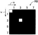
根据本发明,平滑化处理部对RGB图像数据中的规定像素进行平滑化处理。平滑化处理部在图像数据包含复合格雷码数据时,通过将构成该复合格雷码数据的像素设为所述规定像素进行平滑化处理,向构成该复合格雷码数据的像素色信息调入周围像素的色信息,进行平均化。由此,双色化处理部可以将构成复合格雷码数据的像素判定为无彩色。因此,本发明的图像处理装置能够将包含复合格雷码数据的图像数据变换为双色印刷用图像数据、即可以形成高画质的格雷码图像的图像数据。According to the present invention, the smoothing processing unit performs smoothing processing on predetermined pixels in the RGB image data. When the image data includes composite Gray code data, the smoothing processing unit executes smoothing processing by setting pixels constituting the composite Gray code data as the predetermined pixels, and transfers surrounding pixels to pixel color information constituting the composite Gray code data. The color information is averaged. Thereby, the two-colorization processing unit can determine that the pixels constituting the composite Gray code data are achromatic. Therefore, the image processing device of the present invention can convert image data including composite Gray code data into image data for two-color printing, that is, image data capable of forming a high-quality Gray code image.
另外,在本发明中,图像处理装置还具备网点判定部,所述网点判定部在由所述双色化处理部变换处理之前,判定RGB图像数据中的像素是否为网点区域像素,所述平滑化处理部优选构成为,将由所述网点判定部判定为是网点区域像素的像素设为所述规定像素,并对该规定像素进行平滑化处理。In addition, in the present invention, the image processing device further includes a halftone dot judging unit that judges whether or not a pixel in the RGB image data is a halftone dot area pixel before conversion processing by the double-colorization processing unit, and the smoothing The processing unit is preferably configured to set a pixel determined by the halftone dot determination unit to be a halftone dot area pixel as the predetermined pixel, and to perform smoothing processing on the predetermined pixel.
根据本发明,图像处理装置还具备网点判定部,平滑化处理部对网点判定部判定的网点区域像素进行平滑化处理。因此,本发明的图像处理装置不会使文字区域及连续灰度区域界限不清,能够将包含复合格雷码数据的输入图像数据变换为可以形成高画质的格雷码图像的双色印刷用的图像数据。According to the present invention, the image processing device further includes a halftone dot determination unit, and the smoothing processing unit performs smoothing processing on pixels in the halftone dot area determined by the halftone dot determination unit. Therefore, the image processing device of the present invention can convert input image data including composite Gray code data into an image for two-color printing capable of forming a high-quality Gray code image without blurring the boundary between the character area and the continuous gray scale area. data.
另外,在本发明中,图像处理装置还具备对所述规定像素取得与线数关联的信息的线数关联信息取得部,所述平滑化处理部优选构成为,基于由所述线数关联信息取得部取得的信息,变更平滑化的强度,进行平滑化处理。In addition, in the present invention, the image processing apparatus further includes a line number-related information acquisition unit that acquires information related to the line number for the predetermined pixel, and the smoothing processing unit is preferably configured to The information acquired by the acquiring unit changes the intensity of smoothing and performs smoothing processing.
根据本发明,图像处理装置还具备线数关联信息取得部,平滑化处理部基于由线数关联信息取得部取得的信息,变更平滑化的强度,进行平滑化处理。由此,平滑化处理部对每一图像数据都能够进行最适的平滑化处理。因此,本发明的图像处理装置能够将包含复合格雷码数据的输入图像数据变换为可以形成更高画质的格雷码图像的双色印刷用图像数据。According to the present invention, the image processing device further includes the line number-related information acquisition unit, and the smoothing processing unit performs smoothing processing by changing the intensity of smoothing based on the information acquired by the line number-related information acquisition unit. Accordingly, the smoothing processing unit can perform optimal smoothing processing for each image data. Therefore, the image processing device of the present invention can convert input image data including composite Gray code data into image data for two-color printing capable of forming a higher-quality Gray code image.
另外,在本发明中,所述平滑化处理部优选构成为,在表示变更平滑化强度的指示的指示信号从图像处理装置的外部输入时,变更平滑化的强度。In addition, in the present invention, the smoothing processing unit is preferably configured to change the smoothing intensity when an instruction signal indicating an instruction to change the smoothing intensity is input from outside the image processing device.
根据本发明,平滑化处理部在从图像处理装置的外部、例如用户输入表示变更平滑化强度的指示的指示信号时,变更平滑化的强度。因此,平滑化处理部能够通过来自外部的指示对每一图像数据进行最适的平滑化处理。因此,本发明的图像处理装置能够将包含复合格雷码数据的输入图像数据变换为可以形成更高画质的格雷码图像的双色印刷用图像数据。According to the present invention, the smoothing processing unit changes the intensity of smoothing when an instruction signal indicating an instruction to change the intensity of smoothing is input from outside the image processing apparatus, for example, a user. Therefore, the smoothing processing unit can perform optimal smoothing processing for each image data by an instruction from the outside. Therefore, the image processing device of the present invention can convert input image data including composite Gray code data into image data for two-color printing capable of forming a higher-quality Gray code image.
另外,本发明提供一种图像形成装置,其特征在于具备所述图像处理装置。In addition, the present invention provides an image forming apparatus including the image processing apparatus.
根据本发明,图像形成装置具备所述图像处理装置。因此,图像形成装置能够形成降低了有彩色部分和无彩色部分之间的色调间隔的双色图像。According to the present invention, an image forming apparatus includes the image processing device. Therefore, the image forming apparatus can form a two-color image in which the tone interval between the chromatic portion and the achromatic portion is reduced.
另外,由于具备本发明的图像处理装置,因此在双色印刷时,能够形成高画质的格雷码图像。In addition, since the image processing device of the present invention is provided, a high-quality Gray code image can be formed during two-color printing.
另外,本发明提供一种图像处理方法,其包含将读取原稿输入的RGB输入图像数据变换为用于输出由有彩色和无彩色双色构成的双色图像的CMY图像数据的双色化处理工序,其特征为,双色化处理工序包括:亮度彩度算出工序,其基于所述RGB输入图像数据,计算出亮度值及彩度值;图像数据判定工序,其将所述彩度值为规定阈值以上的输入图像数据判定为所述构成双色图像中的有彩色的第一输入图像数据,将所述彩度值小于阈值的输入图像数据判定为所述构成双色图像中的无彩色的第二输入图像数据;输出色生成工序,其对所述第一输入图像数据基于所述亮度值和所述彩度值,且对所述第二输入图像数据基于所述亮度值,生成CMY图像数据。In addition, the present invention provides an image processing method, which includes a two-color processing step of converting RGB input image data input by reading a document into CMY image data for outputting a two-color image composed of chromatic and achromatic two-colors. It is characterized in that the two-color processing step includes: a brightness saturation calculation step, which calculates a brightness value and a saturation value based on the RGB input image data; and an image data determination step, which determines whether the saturation value is greater than a predetermined threshold The input image data is determined as the colored first input image data in the two-color image, and the input image data whose chroma value is smaller than the threshold is determined as the achromatic second input image data in the two-color image. an output color generating step of generating CMY image data based on the luminance value and the chroma value for the first input image data, and based on the luminance value for the second input image data.
根据本发明,图像处理方法包括将RGB输入图像数据变换为用于输出由有彩色和无彩色双色构成的双色图像的CMY图像数据的双色化处理工序。该双色化处理工序包括亮度彩度算出工序、图像数据判定工序和输出色生成工序。亮度彩度算出工序基于RGB输入图像数据,计算出亮度值及彩度值。在图像数据判定工序中,将彩度值为规定阈值以上的输入图像数据判定为构成双色图像中的有彩色的第一输入图像数据,将彩度值小于阈值的输入图像数据判定为构成双色图像中的无彩色的第二输入图像数据。然后,在输出色生成工序中,对第一输入图像数据基于彩度值和亮度值,且对第二输入图像数据基于亮度值,生成CMY图像数据。According to the present invention, the image processing method includes a two-color processing step of converting RGB input image data into CMY image data for outputting a two-color image composed of two colors of chromatic and achromatic. The two-color processing step includes a brightness saturation calculation step, an image data judgment step, and an output color generation step. The luminance and saturation calculation step calculates a luminance value and a saturation value based on the RGB input image data. In the image data judging step, the input image data whose saturation value is equal to or greater than a predetermined threshold is judged as colored first input image data constituting a two-color image, and the input image data whose saturation value is smaller than the threshold is judged to constitute a two-color image. The achromatic second input image data in . Then, in the output color generating step, CMY image data is generated based on the saturation value and the brightness value for the first input image data, and based on the brightness value for the second input image data.
这样,在图像处理方法的双色化处理工序的输出色生成工序中,对构成双色图像中的有彩色的第一输入图像数据基于彩度值和亮度值,生成CMY图像数据,因此C、M、Y各平面的浓度值的最小值不是零,可生成K(黑色)信号。因此,在图像处理方法中,能够降低双色图像的有彩色部分和无彩色部分之间的色调间隔。In this way, in the output color generation step of the two-color processing step of the image processing method, CMY image data is generated based on the chromaticity value and the brightness value for the colored first input image data constituting the two-color image. Therefore, C, M, The minimum value of the density value of each Y plane is not zero, and a K (black) signal can be generated. Therefore, in the image processing method, the tone interval between the chromatic portion and the achromatic portion of the two-color image can be reduced.
在本发明中,图像处理方法具备在由所述双色化处理部变换处理之前,对RGB图像数据中的规定像素进行平滑化处理的平滑化处理工序,所述双色化处理工序优选将平滑化处理后的RGB输入图像数据,变换为用于形成由有彩色和无彩色双色构成的双色图像的CMY图像数据。In the present invention, the image processing method includes a smoothing processing step of performing smoothing processing on predetermined pixels in the RGB image data before conversion processing by the two-color processing unit, and the two-color processing step preferably performs smoothing processing The final RGB input image data is converted into CMY image data for forming a two-color image composed of chromatic and achromatic two-color.
根据本发明,通过平滑化处理工序,对RGB图像数据中的规定像素进行平滑化处理。在平滑化处理工序中,在图像数据包含复合格雷码数据时,通过将构成该复合格雷码数据的像素设为所述规定像素进行平滑化处理,向构成复合格雷码数据的像素的色信息调入周围像素的色信息,进行平均化。由此,在双色化处理步骤中,可以将构成复合格雷码数据的像素判定为无彩色。因此,在本发明的图像处理方法,能够将包含复合格雷码数据的图像数据变换为双色印刷用图像数据、即可以形成高画质的格雷码图像的图像数据。According to the present invention, predetermined pixels in RGB image data are subjected to smoothing processing in the smoothing processing step. In the smoothing processing step, when the image data includes composite Gray code data, by setting the pixels constituting the composite Gray code data as the predetermined pixels and performing the smoothing processing, the color information of the pixels constituting the composite Gray code data is adjusted to The color information of the surrounding pixels is input and averaged. Thus, in the two-color processing step, the pixels constituting the composite Gray code data can be determined to be achromatic. Therefore, in the image processing method of the present invention, image data including composite Gray code data can be converted into image data for two-color printing, that is, image data capable of forming a high-quality Gray code image.
另外,本发明提供一种可计算机读取的记录介质,该记录介质记录有用于使计算机作为上述的图像处理装置的所述双色化处理部发挥功能的图像处理程序。In addition, the present invention provides a computer-readable recording medium in which an image processing program for causing a computer to function as the dual-color processing unit of the above-mentioned image processing device is recorded.
根据本发明,图像处理程序是用于使计算机作为上述图像处理装置的所述双色化处理部发挥功能的程序。这种图像处理程序能够用软件对可以降低双色图像的有彩色部分和无彩色部分之间的色调间隔的图像处理进行控制。另外,图像处理程序能够用软件控制将包含复合格雷码数据的输入图像数据变换为双色印刷用图像数据、即可以形成高画质的格雷码图像的图像数据的图像处理。According to the present invention, the image processing program is a program for causing a computer to function as the two-color processing unit of the image processing device. This image processing program enables software control of image processing that reduces the tone interval between the colored portion and the achromatic portion of a two-color image. Also, the image processing program can use software to control image processing for converting input image data including composite Gray code data into image data for two-color printing, that is, image data capable of forming a high-quality Gray code image.
另外,记录介质是记录有所述图像处理程序且可计算机读取的记录介质,因此通过从可计算机读取的记录介质读出的程序,能够在计算机上实现所述图像处理装置。In addition, since the recording medium is a computer-readable recording medium on which the image processing program is recorded, the image processing device can be realized on a computer by the program read from the computer-readable recording medium.
本发明的目的、特色、及优点从下述的详细说明和附图就会变得更明确。The purpose, features, and advantages of the present invention will become clearer from the following detailed description and accompanying drawings.
附图说明Description of drawings
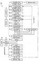
图1是表示本发明第一实施方式的图像形成装置的构成的方框图。FIG. 1 is a block diagram showing the configuration of an image forming apparatus according to a first embodiment of the present invention.
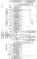
图2是表示双色化处理部的构成的方框图。FIG. 2 is a block diagram showing the configuration of a two-color processing unit.
图3是表示在色指定模式时双色化处理部执行处理的处理顺序的流程图。3 is a flowchart showing a processing procedure of processing executed by a two-color processing unit in a color specifying mode.
图4A~图4C是示意地表示双色化处理部生成的CMY图像数据的各平面的浓度值、和黑色生成/底色去除部生成的C′M′Y′K图像数据的各平面的浓度值的图。4A to 4C schematically show the density values of each plane of CMY image data generated by the two-color processing unit, and the density values of each plane of C'M'Y'K image data generated by the black generation/undercolor removal unit diagram.
图5是表示在有彩色抽取模式时双色化处理部执行处理的处理顺序的流程图。5 is a flowchart showing a processing procedure of processing executed by a two-color processing unit in a color extraction mode.
图6是用于对图像形成装置显示预览时的处理进行说明的图。FIG. 6 is a diagram for explaining processing when the image forming apparatus displays a preview.
图7A及图7B是表示输出灰度修正部使用γ曲线的例子的图。7A and 7B are diagrams showing examples in which the output gradation correction unit uses a γ curve.
图8A及图8B是用于对全彩色模式及单彩色模式时的图像处理进行说明的图。8A and 8B are diagrams for explaining image processing in full-color mode and mono-color mode.
图9A及图9B是用于对全彩色模式及单彩色模式时显示预览时的处理进行说明的图。9A and 9B are diagrams for explaining the processing when displaying a preview in the full-color mode and the mono-color mode.
图10是表示本发明第二实施方式的图像形成装置的构成的方框图。10 is a block diagram showing the configuration of an image forming apparatus according to a second embodiment of the present invention.
图11是表示本发明第三实施方式的图像形成装置的构成的方框图。11 is a block diagram showing the configuration of an image forming apparatus according to a third embodiment of the present invention.
图12是用于对图像形成装置显示预览时的处理进行说明的图。FIG. 12 is a diagram for explaining processing when the image forming apparatus displays a preview.
图13A及图13B是用于对全彩色模式及单彩色模式时的图像处理进行说明的图。13A and 13B are diagrams for explaining image processing in full-color mode and mono-color mode.
图14A及图14B是用于对全彩色模式及单彩色模式时显示预览时的处理进行说明的图。14A and 14B are diagrams for explaining the processing when displaying a preview in the full-color mode and the mono-color mode.
图15A及图15B是表示平滑化滤波器F1及平滑化滤波器F2的图。15A and 15B are diagrams showing the smoothing filter F1 and the smoothing filter F2.
图16是表示平滑化处理部的构成的方框图。FIG. 16 is a block diagram showing the configuration of a smoothing processing unit.
图17是表示由平滑化处理部对一个注目像素处理的流程图。FIG. 17 is a flowchart showing processing of one pixel of interest by a smoothing processing unit.
图18是表示可选择平滑化滤波器时由平滑化处理部对一个注目像素处理的流程图。FIG. 18 is a flowchart showing processing of one pixel of interest by a smoothing processing unit when a smoothing filter is selectable.
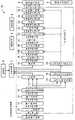
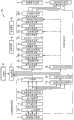
图19是表示本发明第四实施方式的图像形成装置的构成的方框图。19 is a block diagram showing the configuration of an image forming apparatus according to a fourth embodiment of the present invention.
图20是表示平滑化处理部的构成的方框图。FIG. 20 is a block diagram showing the configuration of a smoothing processing unit.
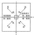
图21A及图21B是用于对从实际空间向频率空间的离散傅里叶变换进行说明的图。21A and 21B are diagrams for explaining discrete Fourier transform from real space to frequency space.
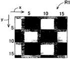
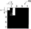
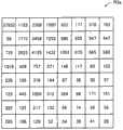
图22A~图22D是用于说明FFT的一个例子的图。22A to 22D are diagrams for explaining an example of FFT.
图23是表示强度矢量R3a的图。FIG. 23 is a diagram showing the intensity vector R3a.
图24是表示区域A0及区域A1的图。FIG. 24 is a diagram showing an area A0 and an area A1.
图25A~图25D是用于对150线的网点图像的FFT进行说明的图。25A to 25D are diagrams for explaining FFT of a 150-line halftone dot image.
图26是表示强度矢量R7a的图。FIG. 26 is a diagram showing the intensity vector R7a.
图27A~图27D是用于对200线的网点图像的FFT进行说明的图。27A to 27D are diagrams for explaining FFT of a 200-line halftone dot image.
图28是表示强度矢量R11a的图。Fig. 28 is a diagram showing the intensity vector R11a.
图29是表示由平滑化处理部对一个注目像素处理的流程图。FIG. 29 is a flowchart showing processing of a pixel of interest by a smoothing processing unit.
图30是表示本发明第五实施方式的图像形成装置的构成的方框图。30 is a block diagram showing the configuration of an image forming apparatus according to a fifth embodiment of the present invention.
具体实施方式Detailed ways
下面,参照附图对本发明的最佳实施方式进行详细地说明。Hereinafter, preferred embodiments of the present invention will be described in detail with reference to the accompanying drawings.
图1是表示本发明第一实施方式的图像形成装置1的构成的方框图。图像形成装置1是当选择复印模式、打印模式、传真发送模式、传真接收模式、图像发送模式中任一模式时执行所选择的模式的数码彩色复合机。FIG. 1 is a block diagram showing the configuration of an
复印模式(复制模式)是读入图像数据(读取原稿生成图像数据)且将该图像数据的图像印刷于用纸的模式。另外,打印模式是将从连接于图像形成装置1的终端装置发送来的图像数据的图像印刷于用纸的模式。传真发送模式是将读取原稿得到的图像数据通过电话线路发送到外部装置的通常的传真模式、和将上述图像数据添附于邮件经由网络发送的网络传真模式。传真接收模式是从外部装置通过传真接收图像数据且将接收到的图像数据的图像印刷于用纸的模式。图像发送模式是(1)将读取原稿生成的图像数据添附于电子邮件并发送到所指定的地址的模式(scan to e-mail模式);(2)将读取原稿生成的图像数据发送到由操作者(用户)指定的文件夹的模式(scan to ftp模式);(3)将读取原稿生成的图像数据发送到安装于图像形成装置1的USB存储器等的模式(scan to usb模式)。The copy mode (copy mode) is a mode for reading image data (reading a document to generate image data) and printing an image of the image data on paper. In addition, the print mode is a mode for printing an image of image data transmitted from a terminal device connected to the
在操作者(用户)从操作面板指定复印模式或打印模式的情况下,图像形成装置1基于操作者的指定执行输出黑白图像的黑白模式、输出全色图像的全彩色模式、输出仅由操作者所希望的一色构成的单色图像的单彩色模式、输出由操作者所希望的有彩色的一色和无彩色(黑色)构成的双色图像的双色彩色模式中的任一动作。When an operator (user) designates a copy mode or a print mode from the operation panel, the
在图像形成装置1中,在复印模式或打印模式时,当利用操作面板等指定单彩色模式时,输出单色图像,当指定双色彩色模式时,输出双色图像。另外,图像形成装置1在单彩色模式时,当利用操作面板等从R(红色)、G(绿色)、B(蓝色)、C(青绿色)、M(深红色)及Y(黄色)中指定所希望的一色时输出由所指定的一色构成的单色图像。In the
图像形成装置1在双色彩色模式时,基于来自操作面板等的操作者的指定,执行有彩色抽取模式及色指定模式中任一动作。图像形成装置1在利用操作面板等指定了有彩色抽取模式的情况下,抽取原稿中的全有彩色,并用操作者事先指定的有彩色(指定输出色)输出该全有彩色,用无彩色(黑色)输出原稿中的其他色部分。另外,图像形成装置1在利用操作面板等指定色指定模式的情况下,从原稿中抽取操作者事先指定的有彩色(指定抽取色),并用操作者事先指定的有彩色(指定输出色)输出该指定抽取色的系统色,用无彩色(黑色)输出原稿中的其他色部分。另外,在图像形成装置1中,上述指定抽取色及上述指定输出色,利用操作面板等,从R(红色)、G(绿色)、B(蓝色)、C(青绿色)、M(深红色)及Y(黄色)中指定所希望的一色。In the two-color mode, the
另外,在本实施方式中,图像形成装置1在复印模式时,可以设定自动判别模式。在设有该自动判别模式的情况下,图像形成装置1进行判别复印对象是彩色原稿还是黑白原稿的自动色彩判别处理(ACS),在判别为彩色原稿的情况下,以全彩色模式进行输出处理,在判别为黑白原稿的情况下,以黑白模式进行输出处理,In addition, in the present embodiment, when the
图像形成装置1的构成包括:图像输入装置2、本发明的图像处理装置3、图像输出装置4、图像显示装置5、控制部6、存储装置7、接收装置8、发送装置9。The
图像输入装置2在复印模式、传真发送模式、图像发送模式时,是构成为可输入彩色图像数据的图像读取部,读取原稿生成图像数据。更具体而言,图像输入装置2通过具备CCD(Charge Coupled Device)图像传感器的扫描器来实现。图像输入装置2将来自原稿的反射光像设为RGB(R:红色、G:绿色、B:蓝色)模拟信号,并用CCD图像传感器读取,将RGB模拟图像数据输出到图像处理装置3。另外,图像输入装置2即使是选择全彩色模式、单彩色模式、双色彩色模式中任一模式的情况,也用全色进行原稿图像的读取。另外,图像输入装置2即使是在图像处理装置3中进行上述的自动色彩判别处理的情况,也用全色进行原稿图像的读取。The
图像处理装置3的详细情况将在后面进行叙述,其是对从图像输入装置2输入的图像数据(图像信号)实施图像处理的集成电路,且由ASIC(Application specific integrated circuit)构成。图像处理装置3在复印模式、传真发送模式、图像发送模式时,对从图像输入装置2输入的图像数据进行图像处理,在打印模式时,对从终端装置发送来的图像数据进行图像处理,在传真接收模式时,对从外部装置接收到的图像数据进行图像处理。而且,图像处理装置3在复印模式、打印模式、传真接收模式时,将实施了图像处理的图像数据发送到图像输出装置4,在传真发送模式时,将实施了图像处理的图像数据发送到发送装置9。另外,图像处理装置3在图像发送模式的“scan to e-mail”模式时,将实施了图像处理的图像数据发送到邮件处理部(未图示),在“scan to ftp”模式时,将实施了图像处理的图像数据发送到规定的文件夹,在“scan to usb”模式时,将实施了图像处理的图像数据发送到规定的USB存储器。Details of the
图像输出装置4用电子照相方式或喷墨方式等打印机实现,基于图像处理装置3进行了图像处理的图像数据,将输出图像印刷(形成)于记录材(例如,记录用纸等)上。另外,本实施方式的“印刷”的意思是指打印模式的印刷、复印模式的印刷、传真接收模式的印刷中的任一种。The image output device 4 is realized by an electrophotographic or inkjet printer, and prints (forms) an output image on a recording material (eg, recording paper) based on the image data processed by the
图像显示装置5是设置于图像形成装置1的操作面板(未图示)的液晶显示器,是可显示彩色图像的显示部。另外,图像显示装置5被触摸面板覆盖,具有作为图像形成装置1的输入接口的功能。即,在图像显示装置5显示用于对图像形成装置1进行各种指令的输入的GUI(图示用户接口)及操作引导。The
另外,在本实施方式的图像形成装置1中,在复印模式或传真接收模式时,在执行印刷前,可以将成为印刷对象的图像的预览显示于图像显示装置5。另外,在本实施方式的图像形成装置1中,在传真发送模式或图像发送模式的执行发送前,可以将成为发送对象的图像的预览显示于图像显示装置5。另外,在图像形成装置1中,在复印模式或图像发送模式时,在选择全彩色模式的情况下,将全色图像的预览显示于图像显示装置5,在选择单彩色模式的情况下,将单色图像的预览显示于图像显示装置5,在选择双色彩色模式的情况下,将双色图像的预览显示于图像显示装置5。另外,图像显示装置5不局限于液晶显示器,也可以为液晶显示器以外的显示部(例如,有机EL显示器、等离子显示器等)。In addition, in the
接收装置8连接于电话线路网或互联网,是通过传真通信从外部装置接收图像数据的装置。另外,发送装置9连接于电话线路网或互联网,是将由图像输入装置2输入的图像数据通过传真通信发往外部装置的装置。The receiving
存储装置7是用于暂时保存由图像处理装置3处理的图像数据的硬盘。另外,控制部6是包含CPU(Central Processing Unit)或DSP(Digital Signal Processor)等处理器的计算机,全面地控制设置于图像形成装置1各种硬件。另外,控制部6还具有控制设置于图像形成装置1各硬件间的数据传输的功能。The
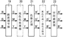
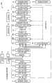
本发明的图像处理装置3具有A/D(模拟/数字)变换部10、黑点修正部11、输入处理部12、原稿类别自动判别部13、区域分离处理部14、压缩部17、区域分离信号压缩部15、解码部18、区域分离信号解码部16、画质调节部19、双色化处理部20、色修正部21、黑色生成/底色去除部22、空间滤波部23、变倍部24、输出灰度修正部25及中间调生成部26的各块。The
对复印模式、传真发送模式、传真接收模式、图像发送模式的各模式,在图像处理装置3的各块执行的处理内容进行详细地说明。另外,在本实施方式的图像处理装置3中,存在着在选择某模式a时动作,但在选择与上述模式a不同的模式b时不动作的块。在此,模式a及模式b为复印模式、传真发送模式、传真接收模式、图像发送模式中的任一模式。另外,在图像处理装置3中也存在着根据所选择的模式(全彩色模式、单彩色模式、双色彩色模式)变更处理内容的块。另外,在图像处理装置3中存在即使所选择的模式(全彩色模式、单彩色模式、双色彩色模式)相同,也在印刷用(发送用)图像数据的处理时动作,但是在预览用图像数据的处理时不动作的块、以及在印刷用(发送用)图像数据的处理时和预览用图像数据的处理时变更处理内容的块。因此,以下,就图像处理装置3所含的各块执行的处理内容,分模式进行说明,并且分别就印刷处理时(或发送处理时)和预览显示时进行说明。The content of processing executed by each block of the
(1)双色彩色模式的图像处理动作(1) Image processing action in two-color mode
(1-1)印刷处理时(图像印刷作业时)(1-1) During printing processing (during image printing work)
借助图1对复印模式且指定双色彩色模式时的图像处理装置3的图像处理动作进行说明。The image processing operation of the
图像处理装置3将从图像输入装置2输入的RGB(R:红色、G:绿色、B:蓝色)的模拟图像数据(RGB模拟信号)依次输送到A/D变换部10、黑点修正部11、输入处理部12、原稿类别自动判别部13、区域分离处理部14及压缩部17,且暂时存储于存储装置7。其后,从存储装置7读出的图像数据依次输送到解码部18、画质调节部19、双色化处理部20、色修正部21、黑色生成/底色去除部22、空间滤波部23、变倍部24、输出灰度修正部25、中间调生成部26,且作为CMYK(C:青绿色、M:深红色、Y:黄色、K:黑色)的数字彩色信号,向图像输出装置4输送。另外,在双色彩色模式时,在图像处理装置3中,不执行色修正部21的处理动作,直接通过。The
A/D变换部10将从图像输入装置2输入的RGB模拟图像数据变换为数字图像数据(RGB数字信号),输送到黑点修正部11。黑点修正部11对从A/D变换部10输送来的数字RGB图像数据,进行消除在图像输入装置2的照明系统、成像系统及摄像系统产生的失真处理。输入处理部12对从黑点修正部11输送来的RGB图像数据的各数据,实施γ修正处理等灰度变换处理。The A/
原稿类别自动判别部13基于由输入处理部12实施了γ修正等灰度变换处理的RGB图像数据(RGB浓度信号),进行由图像输入装置2读取的原稿的类别的判定。在此,作为判定的原稿的类别,具有文字原稿、印刷照相原稿、文字和印刷照相混合的文字印刷照相原稿等。另外,原稿类别自动判别部13也可以基于上述图像数据进行所读取的原稿是彩色原稿还是黑白原稿的判别的处理的自动色彩判别处理(ACS:Auto Color Selection)、及进行是否为空白原稿(是否为全白原稿)的判定处理。另外,从原稿类别自动判别部13输出的RGB图像数据输入到区域分离处理部14及压缩部17。Document type
区域分离处理部14基于从原稿类别自动判别部13输送来的RGB图像数据,对每一输入图像的像素,都判别该像素分类于哪个图像区域,且进行生成表示该判别结果的区域分离信号的处理。在此,在区域分离处理部14中,判别的图像区域具有黑色文字区域、彩色文字区域、网点区域等。另外,区域分离处理部14也可以不是对每一像素都进行图像区域的判定的形态,而是对每一由多个像素构成的块进行图像区域的判定的形态。Based on the RGB image data sent from the document type
压缩部17对从原稿类别自动判别部13输送来的RGB图像数据进行编码处理。另外,上述编码基于例如JPEG(Joint Photographic ExpertsGroup)方式进行。The
区域分离信号压缩部15针对每一像素所生成的区域分离信号实施压缩处理。另外,区域分离信号压缩部15的压缩处理基于例如可逆压缩方法即MMR(Modified Modified Reed)方式或MR(Modified Reed)方式进行。The segmentation
控制部6将从压缩部17输出的编码代码(编码后的图像数据)和从区域分离信号压缩部15输出的区域分离信号代码(压缩后的区域分离信号)暂时保存于存储部7,作为归档数据进行管理。然后,控制部6在指示了复制输出动作的情况下,将上述编码代码及对应于该编码代码的区域分离信号代码从存储部7读出,分别交给解码部18、区域分离信号解码部16。The
另外,控制部6将上述编码代码的保存地址或数据名、和区域分离信号代码的保存地址对应地记入管理表格。即,控制部6利用该管理表格进行编码代码及区域分离信号代码的读出或写入的控制。In addition, the
解码部18通过对上述编码代码实施解码处理,将上述编码代码扩展为RGB图像数据。另外,区域分离信号解码部16对上述区域分离信号代码实施解码处理。解码后的区域分离信号交给黑色生成/底色去除部22、空间滤波部23及中间调生成部26。然后,在黑色生成/底色去除部22、空间滤波部23及中间调生成部26中,根据图像区域的类型,进行图像处理内容的切换。The
画质调节部19对从解码部18输送来的RGB图像数据,进行基底的检测,并进行基底去除修正。另外,画质调节部19基于由操作者(用户)利用操作面板(未图示)输入的设定信息,进行RGB的平衡(色彩调节、红色蓝色之类的整体的色彩调节)、明亮度、鲜艳度的调节。从画质调节部19输出的图像数据在双色彩色模式时为RGB图像数据。The image
双色化处理部20在选择了双色彩色模式的情况下,进行将从画质调节部19输送来的RGB图像数据变换为CMY(C:青绿色、M:深红色、Y:黄色)图像数据的处理。另外,双色化处理部20在选择了全彩色模式的情况下,不对从画质调节部19输出的RGB图像数据进行任何处理,而是直接将该图像数据交给色修正部21(直接通过)。另外,双色化处理部20在选择了单彩色模式的情况下,不对从画质调节部19输出的CMY图像数据进行任何处理,而是直接将该图像数据交给色修正部21。The two-
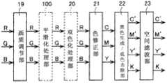
图2是表示双色化处理部20的构成的方框图。双色化处理部20将从画质调节部19输送来的RGB图像数据变换为用于输出由有彩色和无彩色双色构成的双色图像的CMY图像数据。双色化处理部20的构成包括亮度彩度算出部201、指定抽取色判定部202、203、彩度调节处理部204、输出色生成部205。FIG. 2 is a block diagram showing the configuration of the two-
如上所述,图像形成装置1在双色彩色模式时,基于来自操作面板等的操作者的指定,执行有彩色抽取模式及色指定模式中的任一动作。将有彩色抽取模式及色指定模式区别对待,以下对双色彩色模式的双色化处理部20的处理进行说明。As described above, in the two-color mode, the
在图像形成装置1中,在利用操作面板等指定了色指定模式的情况下,图像处理装置3从原稿中抽取操作者预先指定的有彩色(指定抽取色),用操作者预先指定的有彩色(指定抽取色),输出该指定抽取色的系统色,用无彩色(黑色)输出原稿中的其他色部分。另外,上述指定抽取色及上述指定输出色,利用操作面板等,从R(红色)、G(绿色)、B(蓝色)、C(青绿色)、M(深红色)及Y(黄色)中指定所希望的一色。In the
图3是表示色指定模式时双色化处理部20执行处理的处理顺序的流程图。本发明的图像处理方法用图像处理装置3执行,图像处理方法的双色化处理工序用双色化处理部20执行。在色指定模式时双色化处理部20执行的双色化处理工序包含:亮度彩度算出工序、指定抽取色判定工序、图像数据判定工序、彩度调节处理工序、输出色生成工序。FIG. 3 is a flowchart showing a processing procedure performed by the two-
在步骤s1的亮度彩度算出工序中,亮度彩度算出部201对从画质调节部19输送来的RGB图像数据,计算出亮度值及彩度值。由亮度彩度算出部201用下述变换式(1)进行亮度值(Lum)的算出。In the brightness and saturation calculation step of step s1 , the brightness and
(式1)(Formula 1)
Lum=Coefficient_R×In_R+Coefficient_G×In_G+Coefficient_B×In_B …(1)Lum=Coefficient_R×In_R+Coefficient_G×In_G+Coefficient_B×In_B ...(1)
在变换式(1)中,In_R、In_G及In_B表示从画质调节部19输送来的RGB图像数据的R、G、B各平面的像素值。另外,变换式(1)中的Coefficient_R、Coefficient_G及Coefficient_B为预先设定的变换系数,例如,只要设定为Coefficient_R=0.3、Coefficient_G=0.6、Coefficient_B=0.1即可。In conversion formula (1), In_R, In_G, and In_B represent the pixel values of the R, G, and B planes of the RGB image data sent from the image
由亮度彩度算出部201用下述变换式(2)进行彩度值(Chroma)的算出。Calculation of the saturation value (Chroma) is performed by the brightness
(式2)(Formula 2)
Chroma=Max(In_R,In_G,In_B)-Min(In_R,In_G,In_B) …(2)Chroma=Max(In_R, In_G, In_B)-Min(In_R, In_G, In_B) ...(2)
另外,在变换式(2)中,In_R、In_G及In_B表示从画质调节部19输送来的RGB图像数据的R、G、B各平面的像素值。In addition, in conversion formula (2), In_R, In_G, and In_B represent the pixel values of the R, G, and B planes of the RGB image data sent from the image
接着,在步骤s2的指定抽取色判定工序中,指定抽取色判定部202对从画质调节部19输送来的RGB图像数据,基于R、G、B各平面的像素值的大小关系的比较,判定是否为操作者预先指定的对应于原稿中的有彩色(指定抽取色)的输入图像数据。具体而言,指定抽取色判定部202利用下表1判定是否为对应于指定抽取色的输入图像数据。Next, in the designated extracted color determination process of step s2, the designated extracted
表1Table 1

例如,在操作者作为指定抽取色指定了R(红色)的情况下,参照表1的“R(红色)”栏,在满足In_R>R_JudgeR、In_G<R_JudgeG及In_B<R_JudgeB时,指定抽取色判定部202判定为是对应于指定抽取色(R:红色)的输入图像数据,将其以外的图像数据判定为是不对应于指定抽取色的输入图像数据。For example, when the operator designates R (red) as the designated extraction color, refer to the "R (red)" column in Table 1, and when In_R>R_JudgeR, In_G<R_JudgeG, and In_B<R_JudgeB are satisfied, the designated extraction color is judged. The
另外,表1中的In_R、In_G及In_B表示从画质调节部19输送来的RGB图像数据的R、G、B各平面的像素值。表1中的R_JudgeR、R_JudgeG及R_JudgeB是指定抽取色为R(红色)时的预先设定的阈值;G_JudgeR、G_JudgeG及G_JudgeB是指定抽取色为G(绿色)时的预先设定的阈值;B_JudgeR、B_JudgeG及B_JudgeB是指定抽取色为B(蓝色)时的预先设定的阈值;C_JudgeR、C_JudgeG及C_JudgeB是指定抽取色为C(青绿色)时的预先设定的阈值;M_JudgeR、M_JudgeG及M_JudgeB是指定抽取色为M(深红色)时的预先设定的阈值;Y_JudgeR、Y_JudgeG及Y_JudgeB是指定抽取色为Y(黄色)时的预先设定的阈值。这些阈值例如设定为如下表2所示的值。In addition, In_R, In_G, and In_B in Table 1 indicate the pixel values of the R, G, and B planes of the RGB image data sent from the image
(表2)(Table 2)
接着,在步骤s3的图像数据判定工序中,图像数据判定部203基于亮度彩度算出部201算出的彩度值、和指定抽取色判定部202判定的判定结果,判定从画质调节部19输送来的RGB图像数据是否为第一输入图像数据、第二输入图像数据中的任一个。Next, in the image data judging step of step s3 , the image
具体而言,图像数据判定部203将亮度彩度算出部201算出的彩度值为规定的阈值(例如,20)以上、且由指定抽取色判定部202判定为对应于指定抽取色的RGB输入图像数据,判定为构成双色图像中的有彩色的第一输入图像数据。另外,图像数据判定部203将满足第一输入图像数据以外的RGB输入图像数据即亮度彩度算出部201算出的彩度值小于规定的阈值(例如,20)的条件、及由指定抽取色判定部202判定为不对应于指定抽取色的条件中至少一个条件的RGB输入图像数据,判定为构成双色图像中的无彩色的第二输入图像数据。Specifically, the image
接着,在步骤s4的彩度调节处理工序中,彩度调节处理部204对图像数据判定部203判定为是第一输入图像数据的RGB输入图像数据,调节彩度值使彩度变高。具体而言,彩度调节处理部204利用下述变换式(3)对第一输入图像数据实施彩度调节处理。另外,彩度调节处理部204不对第二输入图像数据实施彩度调节处理。Next, in the saturation adjustment processing step of step s4 , the saturation
(式3)(Formula 3)
Out_Chroma=Coefficient_Int×In_Chroma …(3)Out_Chroma=Coefficient_Int×In_Chroma …(3)
变换式(3)中的Out_Chroma表示由彩度调节处理部204彩度调节处理后的彩度值,In_Chroma表示亮度彩度算出部201算出的彩度值,Coefficient_Int是预先设定的常数(例如,1.5)。Out_Chroma in the transformation formula (3) represents the saturation value after the saturation
接着,在步骤s5的输出色生成工序中,输出色生成部205生成CMY图像数据。具体而言,如下述变换式(4)所示,输出色生成部205对第一输入图像数据,基于由彩度调节处理部204彩度调节处理后的彩度值(Out_Chroma)、和亮度彩度算出部201算出的亮度值(Lum),生成CMY图像数据。Next, in the output color generation process of step s5 , the output
(式4)(Formula 4)
Out_C=255-Lum+Out_Chroma×Coefficient_OutROut_C=255-Lum+Out_Chroma×Coefficient_OutR
Out_M=255-Lum+Out_Chroma×Coefficient_OutG …(4)Out_M=255-Lum+Out_Chroma×Coefficient_OutG …(4)
Out_Y=255-Lum+Out_Chroma×Coefficient_OutBOut_Y=255-Lum+Out_Chroma×Coefficient_OutB
变换式(4)中的Out_C、Out_M及Out_Y表示输出色生成部205生成的CMY图像数据的各平面的浓度值。另外,变换式(4)中的Coefficient_OutR、Coefficient_OutG及Coefficient_OutB是根据操作者指定的指定输出色预先设定的变换系数,基于下表3规定。Out_C, Out_M, and Out_Y in the conversion formula (4) represent the density values of the respective planes of the CMY image data generated by the output
表3table 3

例如,在操作者作为指定输出色指定了R(红色)的情况下,参照属于表3的“R(红色)”栏的Coefficient_OutR、Coefficient_OutG及Coefficient_OutB的值,选择Coefficient_OutR=0、Coefficient_OutG=1、Coefficient_OutB=1。For example, when the operator specifies R (red) as the specified output color, refer to the values of Coefficient_OutR, Coefficient_OutG, and Coefficient_OutB belonging to the "R (red)" column of Table 3, and select Coefficient_OutR=0, Coefficient_OutG=1, and Coefficient_OutB =1.
另外,如下述变换式(5)所示,输出色生成部205对第二输入图像数据,基于亮度彩度算出部201算出的亮度值(Lum),生成CMY图像数据。In addition, as shown in the following conversion formula (5), the output
(式5)(Formula 5)
Out_C=255-LumOut_C=255-Lum
Out_M=255-LumOut_M=255-Lum
Out_Y=255-Lum …(5)Out_Y=255-Lum ...(5)
变换式(5)中的Out_C、Out_M及Out_Y表示输出色生成部205生成CMY图像数据的各平面的浓度值。Out_C, Out_M, and Out_Y in the conversion formula (5) represent the density values of the respective planes of the CMY image data generated by the output
如上所述由双色化处理部20生成的CMY图像数据交给色修正部21。色修正部21在选择了双色彩色模式的情况下,不对从双色化处理部20输出的CMY图像数据进行任何处理,直接将该图像数据交给黑色生成/底色去除部22。The CMY image data generated by the two-
黑色生成/底色去除部22在选择了双色彩色模式的情况下,根据从色修正部21输出的CMY图像数据即双色化处理部20生成的CMY图像数据,对K(黑色)图像数据进行基于下述变换式(6)生成的黑色生成。When the two-color color mode is selected, the black generation/
(式6)(Formula 6)
K=min(C,M,Y) …(6)K=min(C, M, Y) ... (6)
另外,如下述变换式(7)所示,黑色生成/底色去除部22在选择了双色彩色模式的情况下,从色修正部21输出的CMY图像数据减去K(黑色)图像数据,生成新的CMY图像数据即C′M′Y′图像数据。In addition, as shown in the conversion formula (7) below, when the two-color color mode is selected, the black generation/
(式7)(Formula 7)
C′=C-KC'=C-K
M′=M-K …(7)M'=M-K ...(7)
Y′=Y-KY'=Y-K
如上所述,在双色彩色模式时,黑色生成/底色去除部22对双色化处理部20生成的CMY图像数据,生成K(黑色)图像数据,并且实施底色去除处理,生成C′M′Y′K图像数据。As described above, in the two-color color mode, the black generation/
在此,利用图4A~图4C对双色化处理部20生成的CMY图像数据、及黑色生成/底色去除部22生成的C′M′Y′K图像数据的浓度值进行说明。Here, the density values of the CMY image data generated by the double-
图4A~图4C是示意地表示双色化处理部20生成的CMY图像数据的各平面的浓度值、和黑色生成/底色去除部22生成的C′M′Y′K图像数据的各平面的浓度值的图。而且,图4A表示双色化处理部20对第一输入图像数据生成的CMY图像数据的浓度值、和由黑色生成/底色去除部22黑色生成底色去除处理后生成的C′M′Y′K图像数据的浓度值的关系。图4B表示双色化处理部20对第二输入图像数据生成的CMY图像数据的浓度值、和由黑色生成/底色去除部22黑色生成底色去除处理后生成的C′M′Y′K图像数据的浓度值的关系。另外,图4C表示现有技术的图像处理装置的对第一输入图像数据生成的CMY图像数据的浓度值、和由黑色生成/底色去除部22黑色生成底色去除处理后生成的C′M′Y′K图像数据的浓度值的关系。FIGS. 4A to 4C schematically show the density values of each plane of CMY image data generated by the dual-
例如,在色指定模式时指定为指定抽取色为R(红色)且指定输出色为R(红色)的情况下,如图4A所示,图像处理装置3的双色化处理部20具有的输出色生成部205对构成双色图像的有彩色(R:红色)的第一输入图像数据,基于彩度值和亮度值,生成CMY图像数据,因此C、M、Y各平面的浓度值的最小值不是零,在黑色生成/底色去除部22,K(黑色)信号可以生成。另外,如图4B所示,输出色生成部205对构成双色图像的无彩色的第二输入图像数据,基于亮度值,生成C、M、Y各平面的浓度值等量的CMY图像数据,通过由黑色生成/底色去除部22黑色生成底色去除处理,生成K(黑色)信号,并且生成C′M′Y′各平面的浓度值为零的C′M′Y′K图像数据。For example, when specifying in the color specifying mode that the specified extracted color is R (red) and the specified output color is R (red), as shown in FIG. The
如上所述,在本实施方式的图像处理装置3中,输出色生成部205对第一输入图像数据,基于彩度值和亮度值,生成C、M、Y各平面的浓度值的最小值不为零的CMY图像数据,因此对构成双色图像的有彩色的第一输入图像数据,也可实现K(黑色)信号的生成,因此,图像处理装置3能够减低在双色图像的有彩色部分和无彩色部分的边界部分颜色的变化明显的不良情况即所谓的色调间隔。As described above, in the
与此相对,在现有技术的图像处理装置中,仅使用彩度值对第一输入图像数据生成CMY图像数据,因而例如在指定抽取色指定为R(红色)且指定输出色指定为R(红色)的情况下,如图4C所示,会生成C平面的浓度值为零的CMY图像数据。所以,在现有技术的图像处理装置中,当向对第一输入图像数据生成的CMY图像数据实施黑色生成底色去除处理时,不会生成K(黑色)信号,K平面的浓度值为零。因此,在现有技术的图像处理装置中,在双色图像的有彩色部分和无彩色部分之间会产生较大的色调间隔。In contrast, in the conventional image processing apparatus, CMY image data is generated for the first input image data using only the chroma value, and therefore, for example, when the specified extraction color is specified as R (red) and the specified output color is specified as R ( In the case of red), as shown in FIG. 4C , CMY image data with a C-plane density value of zero is generated. Therefore, in the conventional image processing device, when the black generation and under color removal processing is performed on the CMY image data generated from the first input image data, the K (black) signal is not generated, and the density value of the K plane is zero. . Therefore, in the prior art image processing apparatus, a large tone interval is generated between the colored portion and the achromatic portion of the two-color image.
另外,在本实施方式中,双色化处理部20具有的输出色生成部205对第一输入图像数据,基于由彩度调节处理部204彩度调节处理后的彩度值和亮度值,生成CMY图像数据,因此,即使在RGB输入图像数据的各像素间R、G、B各平面的像素值的差小的情况下,也能够生成浓度差大的CMY图像数据。In addition, in this embodiment, the output
图5是表示在有彩色抽取模式时双色化处理部20执行处理的处理顺序的流程图。在有彩色抽取模式时双色化处理部20执行的双色化处理工序包含:亮度彩度算出工序、图像数据判定工序、彩度调节处理工序、输出色生成工序。FIG. 5 is a flowchart showing a processing procedure of processing executed by the two-
在图像形成装置1中利用操作面板等指定了有彩色抽取模式的情况下,图像处理装置3抽取原稿中的全有彩色,并用操作者事先指定的有彩色(指定输出色)输出该全有彩色,用无彩色(黑色)输出原稿中的其他色部分。另外,上述指定输出色,利用操作面板等,从R(红色)、G(绿色)、B(蓝色)、C(青绿色)、M(深红色)及Y(黄色)中指定所希望的一色。In the
在步骤a1的亮度彩度算出工序中,亮度彩度算出部201对从画质调节部19输送来的RGB图像数据,计算出亮度值及彩度值。由亮度彩度算出部201用上述变换式(1)进行亮度值(Lum)的算出。另外,由亮度彩度算出部201用上述变换式(2)进行彩度值(Chroma)的算出。另外,在有彩色抽取模式时,不进行指定抽取色判定部202的判定处理。In the brightness and saturation calculation step of step a1 , the brightness and
接着,在步骤a2的图像数据判定工序中,图像数据判定部203基于亮度彩度算出部201算出的彩度值,判定从画质调节部19输送来的RGB图像数据是否为第一输入图像数据、第二输入图像数据中的任一个。Next, in the image data judging process of step a2, the image
具体而言,图像数据判定部203将亮度彩度算出部201算出的彩度值为规定的阈值(例如,20)以上的RGB输入图像数据,判定为构成双色图像的有彩色的第一输入图像数据。另外,图像数据判定部203将第一输入图像数据以外的RGB输入图像数据即亮度彩度算出部201算出的彩度值小于规定的阈值(例如,20)的RGB输入图像数据,判定为构成双色图像的无彩色的第二输入图像数据。Specifically, the image
接着,在步骤a3的彩度调节处理工序中,彩度调节处理部204对图像数据判定部203判定为是第一输入图像数据的RGB输入图像数据,调节彩度值使彩度变高。具体而言,彩度调节处理部204利用上述变换式(3)对第一输入图像数据实施彩度调节处理。另外,彩度调节处理部204不对第二输入图像数据实施彩度调节处理。Next, in the saturation adjustment processing step of step a3 , the saturation
接着,在步骤a4的输出色生成工序中,输出色生成部205生成CMY图像数据。具体而言,如上述变换式(4)所示,输出色生成部205对第一输入图像数据,基于由彩度调节处理部204彩度调节处理后的彩度值(Out_Chroma)、和亮度彩度算出部201算出的亮度值(Lum),生成CMY图像数据。另外,如上述变换式(5)所示,输出色生成部205对第二输入图像数据,基于亮度彩度算出部201算出的亮度值(Lum),生成CMY图像数据。Next, in the output color generation process of step a4, the output
如上所述由双色化处理部20生成的CMY图像数据交给色修正部21。色修正部21在选择了双色彩色模式的情况下,不对从双色化处理部20输出的CMY图像数据进行任何处理,直接将该图像数据交给黑色生成/底色去除部22。The CMY image data generated by the two-
然后,在有彩色抽取模式时,黑色生成/底色去除部22对双色化处理部20生成的CMY图像数据,实施与上述的色指定模式时同样的黑色生成底色去除处理,生成C′M′Y′K图像数据。Then, in the color extraction mode, the black generation/
在有彩色抽取模式时,图像处理装置3的双色化处理部20具有的输出色生成部205对构成双色图像的有彩色的第一输入图像数据,基于彩度值和亮度值,生成CMY图像数据,因此C、M、Y各平面的浓度值的最小值不是零,K(黑色)信号可以生成。因此,图像处理装置3能够降低双色图像的有彩色部分和无彩色部分之间的色调间隔。In the color extraction mode, the output
空间滤波部23对从黑色生成/底色去除部22输出的C′M′Y′K图像数据,基于区域分离信号(区域识别信号),进行由数字滤波器进行空间滤波处理(强调处理、平滑化处理等)。即,在空间滤波部23中,基于区域分离信号,对各图像区域进行不同的图像处理。The
变倍部24对从空间滤波部23输出的C′M′Y′K图像数据,基于经由操作面板由操作者(用户)输入的变倍指令(表示印刷图像的倍率的信息),进行图像的放大或缩小处理。输出灰度修正部25对从变倍部24输出的C′M′Y′K图像数据,进行用于向记录用纸等记录材输出的输出γ修正处理。另外,中间调生成部26对从输出灰度修正部25输出的C′M′Y′K图像数据,利用误差扩散法及高频振动法,执行在图像输出装置4中为印刷图像而必要的灰度再现处理(中间调生成处理)。The
然后,从中间调生成部26输出的C′M′Y′K图像数据交给图像输出装置4,图像输出装置4将该图像数据的双色图像印刷在记录用纸上。Then, the C'M'Y'K image data output from the
(1-2)预览显示时(1-2) When the preview is displayed
图6是用于对图像形成装置1显示预览时的处理进行说明的图。利用图6对复印模式且指定了双色彩色模式时的图像处理装置3的预览显示动作进行说明。FIG. 6 is a diagram for explaining processing when the
在预览显示时,在图像处理装置3中,关于A/D变换部10、黑点修正部11、输入处理部12、原稿类别自动判别部13、区域分离处理部14、压缩部17、区域分离信号压缩部15、解码部18、画质调节部19及双色化处理部20的处理,与上述的印刷处理时相同,因此在下述中省略其说明。In the preview display, in the
如图6所示,区域分离信号解码部16在预览显示时,将解码后的区域分离信号交给空间滤波部23及输出灰度修正部25。另外,在双色彩色模式的预览显示时,色修正部21进行将从双色化处理部20输出的CMY图像数据变换为R′G′B′图像数据的处理。即,色修正部21进行将适合印刷处理的印刷特性的CMY图像数据变换为适合图像显示装置5的显示特性的R′G′B′图像数据的处理。另外,将CMY图像数据变换为R′G′B′图像数据的处理,通过生成将输入值(CMY)和输出值(R′G′B′)对应的LUT(查阅表),且从生成的LUT中检索输出值来实现。As shown in FIG. 6 , the segmentation
黑色生成/底色去除部22在预览显示时,不对从色修正部21输出的R′G′B′图像数据进行任何处理,直接将该图像数据交给后面的空间滤波部23。空间滤波部23在预览显示时,对从黑色生成/底色去除部22输出的R′G′B′图像数据,基于区域分离信号,进行由数字滤波器实现的空间滤波处理(强调处理、平滑化处理等)。即,在空间滤波部23中,与印刷处理时同样,基于区域分离信号,对各图像区域执行不同的图像处理。The black generation/
变倍部24在预览显示时,进行将从空间滤波部23输出的由R′G′B′图像数据构成的图像的像素数变换为图像显示装置5的像素数的中间剔除处理(减少图像数的处理)。当与进行印刷的图像数据的解像度比较时,设置于图像形成装置1的操作面板的图像显示装置5为低解像度,通常为极小型的显示器。因此,在预览显示时,需要中间剔除图像数据。另外,在变倍部24中,基于从设置于图像形成装置1的操作面板输入的变倍指令(表示倍率的信息,例如,2~4倍等固定倍率),实施图像的放大或缩小处理。The
输出灰度修正部25在预览显示时,对从变倍部24输出的由R′G′B′图像数据,基于区域分离信号,进行输出γ修正处理。更具体而言,输出灰度修正部25基于区域分离信号,根据图像区域选择不同的γ曲线,对每一图像区域,都使输出γ修正处理的内容不同。例如,对文字以外的区域,选择图像显示装置5的显示特性相应的γ曲线,对文字区域,选择用于清楚地显示文字的γ曲线。The output
图7A及图7B是表示输出灰度修正部25使用的γ曲线的例子的图。图7A是图像显示装置5的显示特性相应的γ曲线。另外,图7B的实线所示的曲线是用于清楚地显示文字的γ曲线。另外,图7B的虚线是图像显示装置5的显示特性相应的γ曲线,是为与用于清楚地显示文字的γ曲线进行比较而图示的曲线。另外,在本实施方式中,输出灰度修正部25基于区域分离信号,进行γ曲线的选择,但也可以不进行基于区域分离信号的选择,而是仅利用图7A的γ曲线,进行输出灰度修正。7A and 7B are diagrams showing examples of γ curves used by the output
然后,中间调生成部26在预览显示时,不对从输出灰度修正部25输出的R′G′B′图像数据进行任何处理,直接将该图像数据交给后面的图像显示装置5。由此,图像显示装置5可以基于R′G′B′图像数据显示成为复制对象的图像的预览。Then, the
另外,输出灰度修正部25中执行的输出γ修正处理也可以由画质调节部19执行。In addition, the output γ correction processing performed by the output
以上,在选择了复印模式的情况下,对进行预览显示时的处理进行了说明,但在选择了图像发送模式时,也可以根据模式,选择信号变换、处理,并进行预览显示。In the above, when the copy mode is selected, the process for displaying a preview has been described, but when the image transmission mode is selected, signal conversion and processing may be selected according to the mode, and preview display may be performed.
(2)全彩色模式及单彩色模式的图像处理动作(2) Image processing operation in full color mode and monochrome mode
(2-1)印刷处理时(图像印刷作业时)(2-1) During printing processing (during image printing work)
利用图8A及图8B对复印模式且指定全彩色模式时、或复印模式且指定单彩色模式时的图像处理装置3的图像处理动作进行说明。图8A及图8B是用于对全彩色模式及单彩色模式时的图像处理进行说明的图。图8A是对全彩色模式时的图像处理进行说明的图,而图8B是对单彩色模式时的图像处理进行说明的图。在全彩色模式及单彩色模式时,在图像处理装置3中,关于A/D变换部10、黑点修正部11、输入处理部12、原稿类别自动判别部13、区域分离处理部14、压缩部17、区域分离信号压缩部15、解码部18及区域分离信号解码部16的处理,与上述的双色彩色模式时的处理相同,因此以下省略其说明。The image processing operation of the
首先,在全彩色模式时,画质调节部19对从解码部18输送来的RGB图像数据,进行基底的检测,并进行基底去除修正。另外,画质调节部19基于由操作者(用户)利用操作面板输入的设定信息,进行RGB的平衡(色彩调节、红色蓝色之类的整体的色彩调节)、明亮度、鲜艳度的调节。从画质调节部19输出的图像数据在全彩色模式时为RGB图像数据。First, in the full-color mode, the image
如图8A所示,双色化处理部20在选择了全彩色模式的情况下,不对从画质调节部19输送来的RGB图像数据进行任何处理,直接将该图像数据交给色修正部21。As shown in FIG. 8A , when the full-color mode is selected, the two-
色修正部21在选择了全彩色模式的情况下,进行将从双色化处理部20输出的RGB图像数据变换为CMY图像数据的色修正处理,并且对该图像数据实施提高色再现性的处理。另外,上述色修正处理通过生成将输入值(RGB)和输出值(CMY)对应的LUT(查阅表),且从生成的LUT中检索输出值来实现。When the full-color mode is selected, the
黑色生成/底色去除部22在选择了全彩色模式的情况下,进行根据从色修正部21输出的CMY图像数据生成K(黑色)图像数据黑色生成,并且从原来的CMY图像数据中减去K(黑色)图像数据,生成新的CMY图像数据即C′M′Y′图像数据。如上所述,在全彩色模式时,黑色生成/底色去除部22对色修正部21生成的CMY图像数据,生成K(黑色)图像数据,并且实施底色去除处理,生成C′M′Y′K图像数据。When the full-color mode is selected, the black generation/
空间滤波部23对从黑色生成/底色去除部22输出的C′M′Y′K图像数据,基于区域分离信号(区域识别信号),进行由数字滤波器实现的空间滤波处理(强调处理、平滑化处理等)。即,在空间滤波部23中,基于区域分离信号,对各图像区域执行不同的图像处理。The
变倍部24对从空间滤波部23输出的C′M′Y′K图像数据,基于经由操作面板由操作者(用户)输入的变倍指令(表示印刷图像的倍率的信息),进行图像的放大或缩小处理。输出灰度修正部25对从变倍部24输出的C′M′Y′K图像数据,进行用于输出至记录用纸等记录材的输出γ修正处理。另外,中间调生成部26对从输出灰度修正部25输出的C′M′Y′K图像数据,利用误差扩散法及高频振动法,执行在图像输出装置4中为印刷图像而必要的灰度再现处理(中间调生成处理)。然后,从中间调生成部26输出的C′M′Y′K图像数据交给图像输出装置4,图像输出装置4将该图像数据的全彩色图像印刷于记录用纸上。The
接着,利用图8B对单彩色模式时的图像处理装置3的图像处理动作进行说明。Next, the image processing operation of the
画质调节部19在选择了单彩色模式的情况下,进行将从解码部18输送来的RGB图像数据变换为成为RGB的补色的CMY图像数据的处理。在此,单彩色模式时的从RGB图像数据向CMY图像数据的变换处理通过利用下述变换式(8)来进行。When the monochrome mode is selected, the image
(式8)(Formula 8)
(式中,a1=-0.23046875、a2=-0.79296875、a3=0.0234375、c=255)(In the formula, a1=-0.23046875, a2=-0.79296875, a3=0.0234375, c=255)
上述变换式(8)的变换系数r1~r3基于下述表4而定。The conversion coefficients r1 to r3 of the above conversion formula (8) are determined based on Table 4 below.
(表4)(Table 4)

例如,在操作者(用户)在单彩色模式时作为所希望的输出色指定了C(青绿色)的情况下,参照属于表4的“C(青绿色)”栏的r1~r3的值,选择r1=1、r2=0、r3=0。选择了单彩色模式时的来自画质调节部19的输出为CMY图像数据。For example, when the operator (user) specifies C (cyan) as the desired output color in the monochrome mode, refer to the values of r1 to r3 belonging to the "C (cyan)" column of Table 4, Choose r1=1, r2=0, r3=0. The output from the image
另外,画质调节部19进行的鲜艳度的调节,通过在变更了变换式(8)矩阵的r1~r3及a1~a3的各值以后,利用该矩阵可以实现。因此,关于上述鲜艳度的调节、和单彩色模式时的图像数据的变换处理(从RGB向CMY的变换),可以共用矩阵,可以共用图像处理电路。因而,在本实施方式中,上述鲜艳度的调节、和单彩色模式时的图像数据的变换处理用同一处理部(画质调节部)进行。In addition, the adjustment of vividness by the image
如图8B所示,双色化处理部20、色修正部21及黑色生成/底色去除部22在选择了单彩色模式的情况下,不对从画质调节部19输出的CMY图像数据进行任何处理,直接将该图像数据交给空间滤波部23。As shown in FIG. 8B , the two-
在单彩色模式时,空间滤波部23对从黑色生成/底色去除部22输出的CMY图像数据,基于区域分离信号(区域识别信号),进行由数字滤波器实现的空间滤波处理(强调处理、平滑化处理等)。即,在空间滤波部23中,基于区域分离信号,对各图像区域执行不同的图像处理。In the monochrome mode, the
变倍部24对从空间滤波部23输出的CMY图像数据,基于经由操作面板由操作者(用户)输入的变倍指令(表示印刷图像的倍率的信息),进行图像的放大或缩小处理。输出灰度修正部25对从变倍部24输出的CMY图像数据,进行用于输出至记录用纸等记录材的输出γ修正处理。另外,中间调生成部26对从输出灰度修正部25输出的CMY图像数据,利用误差扩散法及高频振动法,执行在图像输出装置4中为印刷图像而必要的灰度再现处理(中间调生成处理)。然后,从中间调生成部26输出的CMY图像数据交给图像输出装置4,图像输出装置4将该图像数据的单彩色图像印刷在记录用纸上。The
(2-2)预览显示时(2-2) When the preview is displayed
利用图9A及图9B对复印模式且指定全彩色模式、或复印模式且指定单彩色模式时的图像处理装置3的预览显示动作进行说明。图9A及图9B是用于对全彩色模式及单彩色模式时预览显示时的处理进行说明的图。图9A是对全彩色模式时的处理进行说明的图,而图9B是对单彩色模式时的处理进行说明的图。在全彩色模式及单彩色模式时,在图像处理装置3中,关于A/D变换部10、黑点修正部11、输入处理部12、原稿类别自动判别部13、区域分离处理部14、压缩部17、区域分离信号压缩部15、解码部18及区域分离信号解码部16的处理,与上述的双色彩色模式时的处理相同,因此以下省略其说明。The preview display operation of the
首先,在全彩色模式时,画质调节部19对从解码部18输送来的RGB图像数据,进行基底的检测,并进行基底去除修正。另外,画质调节部19基于由操作者(用户)利用操作面板输入的设定信息,进行RGB的平衡(色彩调节、红色蓝色之类的整体的色彩调节)、明亮度、鲜艳度的调节。从画质调节部19输出的图像数据在全彩色模式时为RGB图像数据。First, in the full-color mode, the image
如图9A所示,双色化处理部20在选择了全彩色模式的情况下,不对从画质调节部19输出的RGB图像数据进行任何处理,而是直接将该图像数据交给色修正部21。As shown in FIG. 9A , when the full-color mode is selected, the two-
在全彩色模式的预览显示时,色修正部21进行将从双色化处理部20输出的RGB图像数据变换为R′G′B′图像数据的处理。在此,输入到色修正部21的RGB图像数据为适合图像输入装置2(扫描器)的色空间的数据。然后,色修正部21进行将该RGB图像数据向适合图像显示装置5的色空间的R′G′B′图像数据变换的处理。During preview display in the full-color mode, the
即,色修正部21进行将适合图像输入装置2的图像读取特性的RGB图像数据变换为适合图像显示装置5的显示特性的R′G′B′图像数据的处理。另外,将RGB图像数据变换为R′G′B′图像数据的处理,通过生成将输入值(RGB)和输出值(R′G′B′)对应的LUT,且从生成的LUT中检索输出值来实现。而且,在本实施方式中,在全彩色模式时,关于印刷处理时的从RGB图像数据向CMYK图像数据的变换处理、和预览显示时的从RGB图像数据向R′G′B′图像数据的变换处理,共用图像处理回路。That is, the
黑色生成/底色去除部22在预览显示时,不对从色修正部21输出的R′G′B′图像数据进行任何处理,直接将该图像数据交给后面的空间滤波部23。空间滤波部23在预览显示时,对从黑色生成/底色去除部22输出的R′G′B′图像数据,基于区域分离信号,进行由数字滤波器实现的空间滤波处理(强调处理、平滑化处理等)。即,在空间滤波部23中,与印刷处理时同样,基于区域分离信号,对各图像区域执行不同的图像处理。The black generation/
全彩色模式的预览显示时,比空间滤波部23更后面的变倍部24、输出灰度修正部25及中间调生成部26的处理与双色彩色模式的预览显示时的处理相同,省略其说明。During the preview display in the full-color mode, the processing of the
接着,利用图9B对单彩色模式时的图像处理装置3的预览显示动作进行说明。Next, the preview display operation of the
单彩色模式的预览显示时的画质调节部19与单彩色模式的印刷处理时相同,进行将从解码部18输出的RGB图像数据变换为成为RGB的补色的CMY图像数据的处理。如图9B所示,双色化处理部20在选择了单彩色模式的情况下,不对从画质调节部19输出的CMY图像数据进行任何处理,而是直接将该图像数据交给色修正部21。The image
在单彩色模式的预览显示时,色修正部21进行将从双色化处理部20输出的CMY图像数据变换为R′G′B′图像数据的处理。即,色修正部21进行将适合印刷处理的印刷特性的CMY图像数据变换为适合图像显示装置5的显示特性的R′G′B′图像数据的处理。另外,将CMY图像数据变换为R′G′B′图像数据的处理,通过生成将输入值(CMY)和输出值(R′G′B′)对应的LUT,且从所生成的LUT中检索输出值来实现。During preview display in monochrome mode, the
黑色生成/底色去除部22在预览显示时,不对从色修正部21输出的R′G′B′图像数据进行任何处理,直接将该图像数据交给后面的空间滤波部23。空间滤波部23在预览显示时,对从黑色生成/底色去除部22输出的R′G′B′图像数据,基于区域分离信号,进行由数字滤波器实现的空间滤波处理(强调处理、平滑化处理等)。即,在空间滤波部23中,与印刷处理时同样,基于区域分离信号,对各图像区域执行不同的图像处理。The black generation/
另外,在单彩色模式的预览显示时,比空间滤波部23更后面的变倍部24、输出灰度修正部25及中间调生成部26的处理与双色彩色模式的预览显示时的处理同样,省略其说明。In addition, during the preview display in the single-color mode, the processing of the
图10是表示本发明第二实施方式的图像形成装置30的构成的方框图。图像形成装置30与上述的图像形成装置1类似,关于对应的部分采用同一参照符号,省略其说明。图像形成装置30设置有图像处理装置31,以代替设置于图像形成装置1的图像处理装置3。FIG. 10 is a block diagram showing the configuration of an
设置于图像形成装置30的图像处理装置31构成为,在对从图像输入装置2输送的RGB模拟图像数据进行区域分离处理及原稿类别判别处理之前,将RGB图像数据编码,并暂时存储于存储装置7,对从存储装置7读出的解码后的图像数据,实施原稿类别自动判别部13的原稿类别判别处理、及区域分离处理部14的区域分离处理。The image processing device 31 provided in the
图11是表示本发明第三实施方式的图像形成装置40的构成的方框图。图像形成装置40与上述的图像形成装置1类似,关于对应的部分采用同一参照符号,省略其说明。图像形成装置40设置有图像处理装置41,以代替设置于图像形成装置1的图像处理装置3。FIG. 11 is a block diagram showing the configuration of an
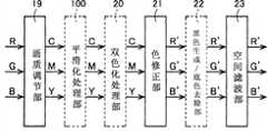
本发明的图像处理装置41具有A/D(模拟/数字)变换部10、黑点修正部11、输入处理部12、原稿类别自动判别部13、区域分离处理部14、压缩部17、区域分离信号压缩部15、解码部18、区域分离信号解码部16、画质调节部19、平滑化处理部100、双色化处理部20、色修正部21、黑色生成/底色去除部22、空间滤波部23、变倍部24、输出灰度修正部25及中间调生成部26各块。The
详细内容将在后面进行叙述,图像处理装置41的特征为具有平滑化处理部100及双色化处理部20。双色化处理部20是将所输入的RGB图像数据变换为CMY图像数据即用于形成由有彩色和无彩色双色构成的双色图像的图像数据的双色化处理部。平滑化处理部100是在由双色化处理部20进行变换处理之前对RGB图像数据中的规定像素进行平滑化处理的平滑化处理部。Details will be described later, but the
(1)双色彩色模式的图像处理动作(1) Image processing action in two-color mode
(1-1)印刷处理时(图像印刷作业时)(1-1) During printing processing (during image printing work)
平滑化处理部100在选择了双色彩色模式的情况下,对从画质调节部19输送来的RGB图像数据中的规定像素进行平滑化处理,关于平滑化处理部100的详细将在后面进行叙述。When the two-color color mode is selected, the smoothing
双色化处理部20在选择了双色彩色模式的情况下,进行将从平滑化处理部100输送来的RGB图像数据变换为CMY(C:青绿色、M:深红色、Y:黄色)图像数据的处理。另外,平滑化处理部100及双色化处理部20在选择了全彩色模式的情况下,不对从画质调节部19输出的RGB图像数据进行任何处理,而是直接将该图像数据交给色修正部21(直接通过)。另外,平滑化处理部100及双色化处理部20在选择了单彩色模式的情况下,不对从画质调节部19输出的CMY图像数据进行任何处理,而是直接将该图像数据交给色修正部21。The two-
(1-2)预览显示时(1-2) When the preview is displayed
图12是用于对图像形成装置40显示预览时的处理进行说明的图。复印模式且指定了双色彩色模式时的、图像处理装置41的预览显示动作与第一实施方式的情况同样,省略其说明。FIG. 12 is a diagram for explaining processing when
(2)全彩色模式及单彩色模式的图像处理动作(2) Image processing operation in full color mode and monochrome mode
(2-1)印刷处理时(图像印刷作业时)(2-1) During printing processing (during image printing work)
利用图13A及图13B对复印模式且指定全彩色模式时、或复印模式且指定单彩色模式时的图像处理装置41的图像处理动作进行说明。图13A及图13B是用于对全彩色模式及单彩色模式时的图像处理进行说明的图。图13A是对全彩色模式时的图像处理进行说明的图,而图13B是对单彩色模式时的图像处理进行说明的图。在全彩色模式及单彩色模式时,在图像处理装置41中,关于A/D变换部10、黑点修正部11、输入处理部12、原稿类别自动判别部13、区域分离处理部14、压缩部17、区域分离信号压缩部15、解码部18及区域分离信号解码部16的处理,与上述的双色彩色模式时的处理相同,因此以下省略其说明。另外,在本实施方式中,关于全彩色模式及单彩色模式时的画质调节部19、色修正部21、黑色生成/底色去除部22及空间滤波部23的处理,与图8A及图8B所示的处理同样,省略其说明。The image processing operation of the
如图13A所示,平滑化处理部100及双色化处理部20在选择了全彩色模式的情况下,不对从画质调节部19输送来的RGB图像数据进行任何处理,直接将该图像数据交给色修正部21。As shown in FIG. 13A , when the full-color mode is selected by the smoothing
如图13B所示,平滑化处理部100、双色化处理部20、色修正部21及黑色生成/底色去除部22在选择了单彩色模式的情况下,不对从画质调节部19输送来的CMY图像数据进行任何处理,直接将该图像数据交给空间滤波部23。As shown in FIG. 13B , the smoothing
(2-2)预览显示时(2-2) When the preview is displayed
利用图14A及图14B对复印模式且指定全彩色模式、或复印模式且指定单彩色模式时的图像处理装置41的预览显示动作进行说明。图14A及图14B是用于对全彩色模式及单彩色模式时预览显示时的处理进行说明的图。图14A是对全彩色模式时的处理进行说明的图,而图14B是对单彩色模式时的处理进行说明的图。在全彩色模式及单彩色模式时,在图像处理装置41中,关于A/D变换部10、黑点修正部11、输入处理部12、原稿类别自动判别部13、区域分离处理部14、压缩部17、区域分离信号压缩部15、解码部18及区域分离信号解码部16的处理,与上述的双色彩色模式时的处理相同,因此以下省略其说明。另外,在本实施方式中,关于全彩色模式及单彩色模式时的画质调节部19、色修正部21、黑色生成/底色去除部22及空间滤波部23的处理,与图9A及图9B所示的处理同样,省略其说明。The preview display operation of the
如图14A所示,平滑化处理部100及双色化处理部20在选择了全彩色模式的情况下,不对从画质调节部19输出的RGB图像数据进行任何处理,而是直接将该图像数据交给色修正部21。As shown in FIG. 14A , when the full-color mode is selected by the smoothing
单彩色模式的预览显示时的画质调节部19与单彩色模式的印刷处理时相同,进行将从解码部18输出的RGB图像数据变换为成为RGB的补色的CMY图像数据的处理。如图14B所示,平滑化处理部100及双色化处理部20在选择了单彩色模式的情况下,不对从画质调节部19输出的CMY图像数据进行任何处理,而是直接将该图像数据交给色修正部21。The image
接着,对本发明的特征部分即平滑化处理部100进行详细地说明。在下述中,图像形成装置40设为选择了双色彩色模式。如上所述,平滑化处理部100在由双色化处理部20进行变换处理之前,对RGB图像数据中的规定像素进行平滑化处理。图像处理装置41可指定各种各样的像素作为规定像素。Next, the smoothing
图像处理装置41构成为,例如,将输入图像数据中的、经由图像显示装置5的操作面板由用户指定的像素(例如,只要利用操作面板指定范围、或利用键盘及鼠标指定范围即可)设为平滑化处理部100进行平滑化处理的规定像素。在这种情况下,在图像形成装置40为双色彩色模式时,图像处理装置41在图像显示装置5显示基于输入图像数据的图像。图像处理装置41将由用户指定的规定范围内的全部像素设为平滑化处理部100进行平滑化处理的规定像素。由此,用户可以将显示于图像显示装置5的图像中的任意部分指定为平滑化处理部100进行平滑化处理的规定像素。The
平滑化处理部100对设为规定像素所指定的像素进行平滑化处理。例如,图15A及图15B所示,平滑化处理部100利用平滑化滤波器F1、平滑化滤波器F2等平滑化滤波器进行平滑化处理。The smoothing
图15A及图15B是表示平滑化滤波器F1及平滑化滤波器F2的图。在图15A及图15B中,矩阵内的数值表示滤波系数。平滑化滤波器F1、平滑化滤波器F2都使用构成为矩阵中心的滤波系数的值大而越向矩阵的周边滤波系数的值越小的加重平均滤波器,但也可以使用其他平滑化滤波器。15A and 15B are diagrams showing the smoothing filter F1 and the smoothing filter F2. In FIGS. 15A and 15B , the numerical values in the matrix represent filter coefficients. Both the smoothing filter F1 and the smoothing filter F2 use a weighted average filter in which the value of the filter coefficient at the center of the matrix is large and the value of the filter coefficient becomes smaller toward the periphery of the matrix, but other smoothing filters can also be used. .
平滑化处理部100通过将平滑化滤波器F1、平滑化滤波器F2等平滑化滤波器应用于输入图像数据,进行平滑化处理。更详细而言,平滑化处理部100例如用以下的(K1)~(K2)的方法进行平滑化处理。The smoothing
(K1)将输入图像数据的全像素一个一个地设为注目像素来选择。(K1) All pixels of the input image data are selected as attention pixels one by one.
(K2)在注目像素为平滑化处理部100进行平滑化处理的规定像素的情况下,进行以下的(K3)~(K6)的处理。(K2) When the pixel of interest is a predetermined pixel to be smoothed by the smoothing
(K3)使注目像素和平滑化滤波器(例如,平滑化滤波器F 1)的中央的滤波系数对应,且使输入图像数据的注目像素的周边像素和平滑化滤波器的周边的滤波系数对应。(K3) Associate the pixel of interest with the filter coefficient at the center of the smoothing filter (for example, smoothing filter F1), and associate the surrounding pixels of the pixel of interest in the input image data with the filter coefficients around the smoothing filter .
(K4)计算滤波系数和相对应的位置的像素的R浓度值之积。(K4) Calculate the product of the filter coefficient and the R density value of the pixel at the corresponding position.
(K5)计算所算出的值的合计值除以滤波系数的合计值的值。也同样地计算出G浓度值、B浓度值。(K5) Calculate the value obtained by dividing the total value of the calculated values by the total value of the filter coefficients. The G density value and the B density value are also calculated in the same manner.
(K6)将关于R浓度值、G浓度值、B浓度值所算出的三个值分别设为平滑化处理后的图像数据的具有与注目像素的坐标相同的坐标的像素的R浓度值、G浓度值、B浓度值。(K6) Let the three values calculated for the R density value, the G density value, and the B density value be the R density value, the G density value, and the G density value of a pixel having the same coordinates as the pixel of interest in the smoothed image data, respectively. Concentration value, B concentration value.
(K7)在注目像素不为平滑化处理部100进行平滑化处理的规定像素的情况下,将该注目像素的R浓度值、G浓度值、B浓度值分别设为平滑化处理后的图像数据的具有与注目像素的坐标相同的坐标的像素的R浓度值、G浓度值、B浓度值。(K7) When the pixel of interest is not a predetermined pixel to be smoothed by the smoothing
由平滑化处理部100进行了平滑化处理后的图像数据输出到双色化处理部20。如上所述,双色化处理部20对从滑化处理部100输入的RGB图像数据,对每一构成该图像数据的像素都判定彩度。双色化处理部20基于所判定的彩度,将所输入的RGB图像数据变换为CMY图像数据即用于形成由有彩色和无彩色双色构成的双色图像的图像数据(双色印刷用图像数据)。如上所述,由双色化处理部20生成的双色印刷用图像数据输出到黑色生成/底色去除部22。The image data smoothed by the smoothing
根据如上所述构成的图像处理装置41,用户作为平滑化处理部100进行平滑化处理的规定像素可以指定输入图像数据中的构成格雷码数据的像素。因此,在格雷码数据为复合格雷码数据的情况下,通过利用平滑化处理部100将复合格雷码数据中的注目像素平滑化,能够向该注目像素调入该注目像素的周围的色信息,将该注目像素平均化。According to the
这样,通过将构成复合格雷码数据的像素平滑化(平均化),双色化处理部20易将构成复合格雷码数据的像素判定为无彩色。在现有图像处理装置中,在构成复合格雷码数据的有彩色的网点区域像素被判定为有彩色的状态下,通过输入图像数据变换为双色印刷用图像数据,会导致复合格雷码图像变换为有彩色和无彩色混合的图像,但是,根据图像处理装置41,能够抑制这种不良情况的发生。因此,根据图像处理装置41,能够将包含复合格雷码数据的图像数据变换为双色印刷用图像数据、即可以形成高画质的格雷码图像的图像数据。Thus, by smoothing (averaging) the pixels constituting the complex Gray code data, the two-
图像处理装置41不是将用户指定的像素设为平滑化处理部100进行平滑化处理的规定像素的构成,优选以将输入图像数据中的网点区域像素设为该规定像素构成。例如,如图16所示,平滑化处理部100包括区域分离信号选择部101和滤波部102,构成为,利用从区域分离处理部14输出的区域分离处理结果,对输入图像数据中的网点区域像素进行平滑化处理。此时,区域分离处理部14作为在由双色化处理部20进行变换处理之前判定图像数据中的像素是否为网点区域像素的网点判定部发挥功能。The
区域分离处理部14利用例如特开2002-232708号公报记载的区域分离处理方法进行区域分离处理。特开2002-232708号公报记载的区域分离处理方法为以下的(L1)~(L2)所示的方法。The
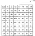
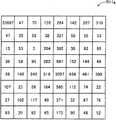
(L1)对RGB的各色成分,计算出图像数据中的包含注目像素的n×m(例如,7像素×5像素)的像素块的最小浓度值及最大浓度值。对RGB的各色成分也进行以下的(L2)~(L8)。(L1) For each RGB color component, calculate the minimum density value and maximum density value of an n×m (for example, 7 pixels×5 pixels) pixel block including the pixel of interest in the image data. The following (L2) to (L8) are also performed for each color component of RGB.
(L2)利用由上述(L1)算出的最小浓度值及最大浓度值,计算出最大浓度差。(L2) Calculate the maximum density difference using the minimum density value and the maximum density value calculated in (L1) above.
(L3)计算注目像素的浓度值和邻接于注目像素的像素的浓度值的浓度差、绝对值的总和即总和浓度繁杂度(例如,对在主扫描方向及副扫描方向上邻接的像素算出的值的和)。(L3) Calculate the density difference between the density value of the pixel of interest and the density values of pixels adjacent to the pixel of interest, and the sum of the absolute values, that is, the total density complexity (for example, calculated for adjacent pixels in the main scanning direction and the sub-scanning direction) sum of values).
(L4)进行由上述(L2)算出的最大浓度差和预定的最大浓度差阈值的比较、及由上述(L3)算出的总和浓度繁杂度和预定的总和浓度繁杂度阈值的比较。(L4) Comparing the maximum density difference calculated by the above (L2) with a predetermined maximum density difference threshold, and comparing the total density complexity calculated by the above (L3) with a predetermined total density complexity threshold.
(L5)在最大浓度差<最大浓度差阈值、及总和浓度繁杂度<总和浓度繁杂度阈值时,判断为注目像素属于基底/感光纸照相区域。(L5) When the maximum density difference<maximum density difference threshold, and the total density complexity<the total density complexity threshold, determine that the pixel of interest belongs to the base/photosensitive paper photographing area.
(L6)在不满足上述(L5)的条件时,判断为注目像素属于文字/网点区域。(L6) When the condition of (L5) above is not satisfied, it is determined that the pixel of interest belongs to the character/half-tone dot area.
(L7)在判断为属于基底/感光纸照相区域的注目像素满足最大浓度差<预定的基底/感光纸照相判定阈值的条件时,将该注目像素分类为基底区域像素,在不满足该条件时,分类为感光纸照相区域像素。(L7) When it is judged that the attention pixel belonging to the background/photosensitive paper photographing area satisfies the condition that the maximum density difference<predetermined base/photosensitive paper photographing judgment threshold value, classify the attention pixel as a base area pixel, and when the condition is not satisfied , classified as photosensitive paper photographic area pixels.
(L8)在判断为属于文字/网点区域的注目像素满足总和浓度繁杂度<(最大浓度差×预定的文字/网点判定阈值)的条件时,将该注目像素分类为文字区域像素,在不满足该条件时,分类为网点区域像素。(L8) When it is judged that the attention pixel belonging to the text/network dot area satisfies the condition of sum density complexity<(maximum density difference×predetermined text/dot dot judgment threshold), the attention pixel is classified as a text area pixel; When this condition is met, it is classified as halftone dot area pixels.
(L9)如上述(L1)~(L8)所述,在对RGB的各色成分进行了区域分离处理之后,基于各色成分的区域分离处理的结果、及规定的优先顺序,进行注目像素的区域判定。进行区域判定时的优先顺序设定为例如(M1)网点、(M2)文字、(M3)感光纸照相、(M4)基底。在这种设定的情况下,例如,当R成分为网点区域像素、G成分为文字区域像素、B成分为基底区域像素时,区域分离后的一个注目像素被判定为网点区域像素。(L9) As described in (L1) to (L8) above, after the region separation processing is performed on each color component of RGB, the region determination of the pixel of interest is performed based on the result of the region separation processing of each color component and a predetermined priority order. . The order of priority when performing area determination is set to, for example, (M1) dot, (M2) characters, (M3) photosensitive paper, (M4) base. In this setting, for example, when the R component is a halftone dot area pixel, the G component is a character area pixel, and the B component is a base area pixel, one pixel of interest after segmentation is determined to be a halftone dot area pixel.
平滑化处理部100也可以不构成为参照区域分离结果进行平滑化处理,而是构成为将输入图像数据的全部像素设为该规定像素。在这种情况下,图像处理装置41构成为,在图像形成装置40为双色彩色模式、且图像输入装置2读取的原稿的原稿类别为由印刷照相构成的原稿(网点原稿)时,将输入图像数据的全部像素设为平滑化处理部100进行平滑化处理的规定像素。图像处理装置41也可以构成为,将图像输入装置2读取的原稿的原稿类别设为经由图像显示装置5的操作面板而用户指定的原稿类别,也可以构成为,设为原稿类别自动判别部13的判别结果。原稿类别自动判别部13利用例如与上述的区域分离处理部14相同的方法进行区域分离,且利用区域分离结果进行原稿类别的判别。在这种情况下,只要可以判别原稿的类别即可,因此也可以在进行像素的判别时,不是将全部像素设为对象,而是对像素进行抽样(对区域分离结果进行抽样),并进行原稿类别的判别,或者,在进行区域分离时,将阈值附近的具有特征量的像素排除,选择可以可靠地进行区域分离的像素,进行原稿类别的判别。The smoothing
原稿类别自动判别部13分别将区域分离处理的结果、判定为基底区域像素的像素的像素数、判定为文字区域像素的像素的像素数、判定为网点区域像素的像素的像素数、及判定为感光纸照相区域像素的像素的像素数存储。原稿类别自动判别部13根据所存储的各区域像素的像素数和预定的判定阈值,进行原稿类别的判别。更详细而言,原稿类别自动判别部13基于以下的(N1)~(N8)的标准,进行原稿类别的判别。The document type
(N1)将文字区域像素数为全部区域像素数的30%以上、且网点区域像素数小于全部区域像素数的20%、且感光纸照相区域像素数小于全部区域像素数的10%的图像数据设为文字原稿。(N1) Image data in which the number of pixels in the text area is more than 30% of the number of pixels in the entire area, the number of pixels in the dot area is less than 20% of the number of pixels in the entire area, and the number of pixels in the photographic area of photosensitive paper is less than 10% of the number of pixels in the entire area Set as text original.
(N2)将文字区域像素数小于全部区域像素数的30%、且网点区域像素数为全部区域像素数的20%以上、且感光纸照相区域像素数小于全部区域像素数的10%的图像数据设为网点原稿。(N2) Image data in which the number of pixels in the text area is less than 30% of the number of pixels in the entire area, the number of pixels in the dot area is more than 20% of the number of pixels in the entire area, and the number of pixels in the photographic area of photosensitive paper is less than 10% of the number of pixels in the entire area Set as halftone dot original.
(N3)将文字区域像素数小于全部区域像素数的30%、且网点区域像素数小于全部区域像素数的20%、且感光纸照相区域像素数为全部区域像素数的10%以上的图像数据设为感光纸照相原稿。(N3) Image data in which the number of pixels in the text area is less than 30% of the number of pixels in the entire area, the number of pixels in the dot area is less than 20% of the number of pixels in the entire area, and the number of pixels in the photographic area of photosensitive paper is more than 10% of the number of pixels in the entire area Set to photographic originals on photosensitive paper.
(N4)将文字区域像素数为全部区域像素数的30%以上、且网点区域像素数为全部区域像素数的20%以上、且感光纸照相区域像素数小于全部区域像素数的10%的图像数据设为文字/网点原稿。(N4) Images in which the number of pixels in the text area is more than 30% of the number of pixels in the entire area, the number of pixels in the dot area is more than 20% of the number of pixels in the entire area, and the number of pixels in the photographic area of photosensitive paper is less than 10% of the number of pixels in the entire area The data is set as text/dot original.
(N5)将文字区域像素数为全部区域像素数的30%以上、且网点区域像素数小于全部区域像素数的20%、且感光纸照相区域像素数为全部区域像素数的10%以上的图像数据设为文字/感光纸照相原稿。(N5) Images in which the number of pixels in the text area is more than 30% of the number of pixels in the entire area, the number of pixels in the dot area is less than 20% of the number of pixels in the entire area, and the number of pixels in the photographic area of photosensitive paper is more than 10% of the number of pixels in the entire area The data is set as a text/sensitized paper photographic original.
在如上所述由原稿类别自动判别部13判别的原稿类别为网点原稿的情况、或由用户指示为原稿类别为网点原稿的情况下,平滑化处理部100对输入图像数据的全部像素进行平滑化处理。如上所述,平滑化处理部100利用平滑化滤波器F1、平滑化滤波器F2等平滑化滤波器进行平滑化处理。由平滑化处理部100进行了平滑化处理的图像数据输入到双色化处理部20。When the document type discriminated by the document type
这样,图像处理装置41在原稿类别为网点原稿时,对输入图像数据的全部像素进行平滑化处理。在网点原稿的格雷码彩色图像由复合格雷码图像构成时,通过对输入图像数据的全部像素进行平滑化处理,即使用户未指定格雷码图像区域,也能够将输入图像数据中的复合格雷码数据平滑化。In this way, the
由此,如上所述,能够将构成复合格雷码数据的像素平滑化。因此,能够抑制导致复合格雷码图像变换为有彩色和无彩色混合的图像。因而,即使用户未指定格雷码图像区域,也能够将包含复合格雷码数据的图像数据变换为可以形成高画质的格雷码图像的双色印刷用图像数据。Thereby, as described above, the pixels constituting the complex Gray code data can be smoothed. Therefore, it is possible to suppress the conversion of the composite Gray code image into an image in which chromatic and achromatic colors are mixed. Therefore, even if the user does not designate a Gray code image area, image data including composite Gray code data can be converted into image data for two-color printing capable of forming a high-quality Gray code image.
图16是表示平滑化处理部100的构成的方框图。区域分离信号选择部101以全部像素为对象而每一个像素都设为注目像素来选择。经由区域分离信号解码部16,向区域分离信号选择部101输入从区域分离处理部14输出的区域分离处理结果。区域分离信号选择部101在注目像素为网点区域像素的情况下,将该注目像素判断为平滑化处理部100进行平滑化处理的规定像素,将该注目像素的坐标向滤波部102输出。区域分离信号选择部101在注目像素不是网点区域像素的情况下,将该注目像素的R、G、B浓度值设为由平滑化处理部100平滑化处理后的图像数据的、具有与该注目像素的坐标相同的坐标的像素的R、G、B浓度值。FIG. 16 is a block diagram showing the configuration of the smoothing
滤波部102存储平滑化滤波器F 1及平滑化滤波器F2等平滑化滤波器。如上所述,滤波部102根据从区域分离信号选择部101输入的注目像素的坐标、和输入到平滑化处理部100的输入图像数据,利用平滑化滤波器,对输入了坐标的注目像素进行平滑化处理。滤波部102将通过平滑化处理而得到的R、G、B浓度值设为平滑化处理后的图像数据的、具有与注目像素的坐标相同的坐标的像素的R、G、B浓度值。The
图17是表示由平滑化处理部100进行对一个注目像素的处理的流程图。首先,区域分离信号选择部101从输入图像数据中设定一个像素作为注目像素(步骤s101)。接着,区域分离信号选择部101判断注目像素是否为网点区域像素(步骤s102)。在步骤s102中判断为注目像素是网点区域像素的情况下,区域分离信号选择部101将该注目像素的坐标向滤波部102输出。滤波部102基于从区域分离信号选择部101输入的注目像素的坐标,对该注目像素进行平滑化处理,且将通过平滑化处理而得到的R、G、B浓度值设为平滑化处理后的图像数据的、具有与该注目像素的坐标相同的坐标的像素的R、G、B浓度值(步骤s103)。在步骤s102中判断为注目像素不是网点区域像素的情况下,滤波部102不进行该注目像素的平滑化处理,区域分离信号选择部101将该注目像素的R、G、B浓度值设为由平滑化处理部100平滑化处理后的图像数据的、具有与该注目像素的坐标相同的坐标的像素的R、G、B浓度值(步骤s104)。平滑化处理部100当结束步骤s103或步骤s104的处理时,结束对一个注目像素的处理。FIG. 17 is a flowchart showing processing performed on one pixel of interest by the smoothing
平滑化处理部100对输入图像数据的全部像素进行这种对一个注目像素的处理,对输入图像数据中的网点区域像素进行平滑化处理。由此,平滑化处理部100生成输入图像数据中的网点区域像素进行了平滑化处理后的图像数据。由平滑化处理部100生成的图像数据向双色化处理部20输入。The smoothing
这样,在图像处理装置41中,平滑化处理部100利用从区域分离处理部14输出的区域分离处理结果,对输入图像数据中的网点区域像素进行平滑化处理。由于复合格雷码数据是分别具有多种有彩色的网点区域像素的集合,因此根据图像处理装置41,即使用户未指定格雷码图像区域,也能够将输入图像数据中的复合格雷码数据平滑化。另外,由于图像处理装置41并不是对输入图像数据中的全部像素进行平滑化处理,因此不会使文字区域及连续灰度区域界限不清,能够将复合格雷码数据平滑化。In this way, in the
由此,如上所述,能够将构成复合格雷码数据的像素平滑化。因此,能够抑制复合格雷码图像变换为有彩色和无彩色混合的图像。因而,即使用户未指定格雷码图像区域,也能够将包含复合格雷码数据的图像数据变换为可以形成高画质的格雷码图像的双色印刷用图像数据。Thereby, as described above, the pixels constituting the complex Gray code data can be smoothed. Therefore, it is possible to suppress conversion of the composite Gray code image into an image in which chromatic and achromatic colors are mixed. Therefore, even if the user does not designate a Gray code image area, image data including composite Gray code data can be converted into image data for two-color printing capable of forming a high-quality Gray code image.
这样,图像处理装置41利用包含平滑化处理步骤和双色化处理步骤的图像处理方法,生成可以形成高画质的格雷码图像的双色印刷用图像数据,其中,所述平滑化处理步骤,对所输入的RGB图像数据中的规定像素进行平滑化处理;所述双色化处理步骤,将在该平滑化处理步骤中进行了平滑化处理的图像数据变换为CMY图像数据、即用于形成由有彩色和无彩色双色构成的双色图像的图像数据(双色印刷用图像数据)。In this way, the
另外,图像处理装置41的平滑化处理部100,作为用于平滑化处理的平滑化滤波器,既可以存储平滑化滤波器F1,也可以存储平滑化滤波器F2。平滑化滤波器F1和平滑化滤波器F2的差别为构成平滑化滤波器的矩阵的大小。如图15A所示,平滑化滤波器F1的滤波器尺寸小,适用于注目像素的周围比较小的范围。当利用平滑化滤波器F1进行平滑化处理时,能够保留图像的鲜明性,同时能够进行图像的平滑化。In addition, the smoothing
如图15B所示,平滑化滤波器F2的滤波器尺寸大,适用于注目像素的周围比较大的范围。当利用平滑化滤波器F2进行平滑化处理时,能够使图像更平滑地进行图像的平滑化。即,与平滑化滤波器F1相比,平滑化滤波器F2会较高地构成平滑化的强度(平滑化强度)。As shown in FIG. 15B , the smoothing filter F2 has a large filter size and is suitable for a relatively wide range around the pixel of interest. When the smoothing process is performed by the smoothing filter F2, the image can be smoothed more smoothly. That is, the smoothing filter F2 has higher smoothing strength (smoothing strength) than the smoothing filter F1.
在上述图像处理装置41中,平滑化处理部100也可以为如下构成,即,在从图像处理装置41的外部输入表示变更平滑化强度指示的指示信号时(例如,经由图像显示装置5的操作面板,由用户输入变更平滑化强度的指示时),变更平滑化强度。例如,平滑化处理部100存储有平滑化滤波器F1及平滑化滤波器F2任一个滤波器,构成为,在没有来自用户的指示的情况下,利用平滑化滤波器F1进行平滑化处理,在用户指示使平滑化强度提高时,利用平滑化滤波器F2进行平滑化处理。另外,例如,图像处理装置41也可以构成为,在由平滑化处理部100平滑化处理前,将“使平滑”及“使更平滑”显示于图像显示装置5,促使用户进行平滑化强度的选择。在这种情况下,图像处理装置41构成为,当用户按下“使平滑”时,平滑化处理部100利用平滑化强度较低的平滑化滤波器F1进行平滑化处理,当用户按下“使更平滑”时,平滑化处理部100利用平滑化强度较高的平滑化滤波器F2进行平滑化处理。In the
对这样构成为可从外部选择平滑化滤波器的图像处理装置41的平滑化处理部100的处理进行说明。在此,平滑化处理部100包含区域分离信号选择部101和滤波部102而构成,以使其利用原稿类别自动判别部13的区域分离结果,对网点区域像素进行平滑化处理。另外,滤波部102存储有平滑化滤波器F1和平滑化滤波器F2。The processing of the smoothing
图18是表示可选择平滑化滤波器时由平滑化处理部100对一个注目像素的处理的流程图。首先,区域分离信号选择部101从输入图像数据中设定一个像素作为注目像素(步骤s201)。接着,区域分离信号选择部101判断注目像素是否为网点区域像素(步骤s202)。在步骤s202中判断为注目像素是网点区域像素的情况下,区域分离信号选择部101将该注目像素的坐标向滤波部102输出。FIG. 18 is a flowchart showing the processing of one pixel of interest by the smoothing
滤波部102判断由用户选择的平滑化滤波器是平滑化滤波器F1还是平滑化滤波器F2(步骤s203)。在步骤s203中判断为由用户选择的平滑化滤波器是平滑化滤波器F1的情况下,滤波部102基于从区域分离信号选择部101输入的注目像素的坐标,利用平滑化滤波器F1对该注目像素进行平滑化处理,且将通过平滑化处理而得到的R、G、B浓度值设为平滑化处理后的图像数据的、具有与该注目像素的坐标相同的坐标的像素的R、G、B浓度值(步骤s204)。在步骤s203中判断为由用户选择的平滑化滤波器是平滑化滤波器F2的情况下,滤波部102基于从区域分离信号选择部101输入的注目像素的坐标,利用平滑化滤波器F2对该注目像素进行平滑化处理,且将通过平滑化处理而得到的R、G、B浓度值设为平滑化处理后的图像数据的、具有与该注目像素的坐标相同的坐标的像素的R、G、B浓度值(步骤s205)。The
在步骤s202中判断为注目像素不是网点区域像素的情况下,滤波部102不进行该注目像素的平滑化处理,区域分离信号选择部101将该注目像素的R、G、B浓度值设为平滑化处理部100的平滑化处理后的图像数据的、具有与该注目像素的坐标相同的坐标的像素的R、G、B浓度值(步骤s206)。平滑化处理部100当结束步骤s204、步骤s205、或步骤s206的处理时,结束对一个注目像素的处理。If it is determined in step s202 that the pixel of interest is not a pixel in the halftone dot area, the
通过这样构成图像处理装置41,用户能够选择平滑化处理部100用于平滑化处理的平滑化滤波器。另外,平滑化滤波器F1、F2是平滑化滤波器的一个例子,平滑化处理部100也可以使用除这些之外的平滑化滤波器。By configuring the
另外,图像处理装置41也可以构成为,选择是否边看使用用户所选择的平滑化滤波器时的预览边输出图像数据。例如,图像处理装置41将平滑化处理部100使用用户所选择的平滑化滤波器进行平滑化处理时的预览,显示于图像显示装置5。用户可以边看显示于图像显示装置5的预览,边经由图像显示装置5的操作面板,选择允许输出或拒绝输出的任一个。另外,此时,用户也可以通过操作操作面板,将放大了预览的任意部分的放大图像显示于图像显示装置5。图像处理装置41仅在由用户选择了允许输出的情况下,才将图像数据输出到图像输出装置4。In addition, the
根据这样构成的图像处理装置41,由于选择是否边看使用所选择的平滑化滤波器时的预览边输出图像数据,因此用户能够选择适当的平滑化滤波器,且使平滑化处理部100进行平滑化处理,能够输出可以形成更高画质的格雷码图像的双色印刷用图像数据。According to the
接着,对本发明第四实施方式的设置于图像形成装置40A的图像处理装置41A进行说明。图19是表示本发明第四实施方式的图像形成装置40A的构成的方框图。图像形成装置40A与上述的图像形成装置40类似,关于对应的部分采用同一参照符号,省略其说明。图像形成装置40A设置有图像处理装置41A,以代替设置于图像形成装置40的图像处理装置41。Next, an image processing device 41A provided in an image forming device 40A according to a fourth embodiment of the present invention will be described. FIG. 19 is a block diagram showing the configuration of an image forming apparatus 40A according to a fourth embodiment of the present invention. The image forming apparatus 40A is similar to the
图像处理装置41A具备平滑化处理部100A,以代替平滑化处理部100,除还具备线数关联信息取得部103以外,与图像处理装置41的构成相同。线数关联信息取得部103是对平滑化处理部100A进行平滑化处理的规定像素取得与线数关联的信息(线数关联信息)的线数关联信息取得部。另外,“线数”是形成图像时的网点的密度,在本发明中,在表述为“规定像素的线数”等的情况下,意思是“以规定像素为中心的规定范围的线数”。The image processing device 41A includes a smoothing processing unit 100A instead of the smoothing
图像处理装置41A的特征在于构成为,平滑化处理部100A基于由线数关联信息取得部103取得的线数关联信息,变更平滑化强度进行平滑化处理。即,本发明第三实施方式的设置于图像形成装置40的图像处理装置41是平滑化处理部100使用用户所选择的平滑化滤波器进行平滑化处理的图像处理装置,与此相对,本发明第四实施方式的设置于图像形成装置40A的图像处理装置41A是以如下方式构成的图像处理装置,即,基于来自线数关联信息取得部103的线数关联信息,选择平滑化处理部100A用于平滑化处理的平滑化滤波器。The image processing device 41A is characterized in that the smoothing processing unit 100A performs smoothing processing by changing the smoothing intensity based on the line number-related information acquired by the line number-related information acquisition unit 103 . That is, the
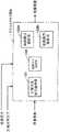
例如,图像处理装置41A构成为,线数关联信息取得部103利用原稿类别自动判别部13的区域分离信号,取得图像数据中的网点区域像素的线数关联信息,平滑化处理部100A将网点区域像素设为进行平滑化处理的规定像素,基于线数关联信息,选择用于该平滑化处理的平滑化滤波器。在这种情况下,图像处理装置41A的构成为,除具备图像处理装置41的构成以外,还具备线数关联信息取得部103,具备图20所示的平滑化处理部100A,以代替平滑化处理部100。For example, the image processing device 41A is configured such that the line number-related information acquisition unit 103 acquires the line number-related information of pixels in the halftone dot area in the image data using the area separation signal from the document type
图20是表示平滑化处理部100A的构成的方框图。平滑化处理部100A包含区域分离信号选择部101、线数信号选择部104、存储平滑化滤波器F1的高线数用滤波部102A、和存储平滑化滤波器F2的低线数用滤波部102B。区域分离信号选择部101与平滑化处理部100具备的区域分离信号选择部101相同。FIG. 20 is a block diagram showing the configuration of the smoothing processing unit 100A. The smoothing processing unit 100A includes a region separation
线数关联信息取得部103对规定像素取得线数关联信息,且输出到存储装置7。在本实施方式中,取得线数关联信息的对象即规定像素为网点区域像素。线数关联信息是例如规定像素的线数的值、及规定像素的线数是否为预定的规定阈值以上等与线数关联的信息。在本实施方式中,线数关联信息是网点区域像素的线数是否为预定的规定阈值以上的信息。The number-of-lines-related information acquisition unit 103 acquires the number-of-lines-related information for a predetermined pixel, and outputs the information to the
线数关联信息取得部103判定作为注目像素的网点区域像素的线数是否为预定的规定阈值以上(是高线数还是低线数)。The number-of-lines-related information acquisition unit 103 determines whether the number of lines of the pixel in the halftone dot area, which is the pixel of interest, is equal to or greater than a predetermined threshold (whether the number of lines is high or the number of lines is low).
平滑化处理部100A基于输入到区域分离信号选择部101的注目像素是否为网点区域像素的信息(区域分离信号)、和输入到线数信号选择部104的注目像素是否为构成复合格雷码数据的像素的信息、及注目像素是高线数还是低线数的信息(线数信号),进行平滑化处理。平滑化处理部100A对网点区域像素且为高线数的注目像素,利用高线数用滤波部102A存储的平滑化滤波器F1,进行平滑化处理。另外,平滑化处理部100A对网点区域像素且不是高线数(即,为低线数)的注目像素,利用低线数用滤波部102B存储的平滑化滤波器F2,进行平滑化处理。另外,平滑化处理部100A对不是网点区域像素的注目像素不进行平滑化处理。平滑化处理部100A的详细将在后面进行叙述。The smoothing processing section 100A is based on the information (area separation signal) whether the pixel of interest input to the area separation
线数关联信息取得部103的线数关联信息的取得处理大致由以下的(O1)~(O4)的处理构成。The acquisition processing of the number-of-line-related information by the number-of-line-related information acquisition unit 103 is roughly constituted by the following processes ( O1 ) to ( O4 ).
(O1)对实际空间的图像数据(RGB输入图像数据)中的、包含注目像素的规定范围的像素的R浓度值进行离散傅里叶变换,可以得到频率空间的表示各块的强度的数据(强度矢量数据)。(01) Discrete Fourier transform is performed on the R density values of pixels in a predetermined range including the pixel of interest in the image data (RGB input image data) in real space, and data representing the intensity of each block in frequency space can be obtained ( intensity vector data).
(O2)分别计算出频率空间中的规定的两个区域的、各块的强度的平均值。(O2) Calculate the average value of the intensity of each block in two predetermined regions in the frequency space.
(O3)将上述规定的两个区域的平均值进行比较,在R平面时,判定注目像素的线数是否为预定的规定阈值以上。(O3) Comparing the average values of the above-mentioned two predetermined regions, and in the case of the R plane, it is judged whether or not the number of lines of the pixel of interest is equal to or greater than a predetermined predetermined threshold.
(O4)关于G平面、B平面,也进行上述(O1)~(O3)的处理。(O4) The above-mentioned processes (O1) to (O3) are also performed on the G plane and the B plane.
由线数关联信息取得部103线数关联信息的取得处理方法也可以为除这些以外的方法。例如,以下列举的(P1)~(P4)四种方法。The acquisition processing method of the line number related information by the line number related information acquisition part 103 may be a method other than these. For example, four methods (P1) to (P4) listed below.
(P1)在上述(O1)中,对注目像素的亮度值Y(=0.3×R+0.59×G+0.11×B)进行离散傅里叶变换,得到频率空间的表示各块的强度的数据(强度矢量数据),进行与上述(O2)、(O3)同样的处理,判定注目像素的线数是否为预定的规定阈值以上的方法。(P1) In the above (O1), discrete Fourier transform is performed on the luminance value Y (=0.3×R+0.59×G+0.11×B) of the pixel of interest to obtain data representing the intensity of each block in the frequency space ( Intensity vector data) is a method of performing the same processing as above (O2) and (O3) to determine whether or not the number of lines of the pixel of interest is equal to or greater than a predetermined predetermined threshold.
(P2)在判定为是网点区域的局部块中,利用规定的阈值,计算出二值数据的反转次数的平均值,基于该平均值判定线数的方法(特开2006-203703号公报记载的方法)。(P2) In a local block determined to be a halftone dot area, using a predetermined threshold, calculate the average value of the number of inversions of binary data, and determine the number of lines based on the average value (JP-A-2006-203703 describes Methods).
(P3)变更阈值且检出网点区域像素,利用网点区域像素数的比率,判定是高线数还是低线数的方法(特开2004-328292号公报记载的方法)。(P3) A method of changing the threshold, detecting pixels in the halftone dot area, and judging whether the number of lines is high or low by using the ratio of the number of pixels in the halftone dot area (the method described in JP-A-2004-328292).
(P4)利用二值数据的反转次数,判定线数的方法(特开2006-197037号公报记载的方法)。(P4) A method of determining the number of lines using the number of inversions of binary data (the method described in JP-A-2006-197037).
下面,对线数关联信息取得部103的上述(O1)~(O4)的处理进行详细地说明。图21A及图21B是用于对从实际空间向频率空间的离散傅里叶变换进行说明的图。在上述(O1)中,线数关联信息取得部103通过应用像素掩模G,分别向输入图像数据的规定范围的像素分配用于傅里叶变换的坐标(x,y)。Next, the processing of the above (O1) to (O4) of the line number-related information acquisition unit 103 will be described in detail. 21A and 21B are diagrams for explaining discrete Fourier transform from real space to frequency space. In (O1) above, the line number-related information acquiring unit 103 applies the pixel mask G to assign coordinates (x, y) for Fourier transform to pixels in a predetermined range of the input image data.
图21A表示用于傅里叶变换的像素掩模G。本实施方式使用的像素掩模G由配置为正方形状的多个像素构成,像素数为16×16(=256)。像素掩模G构成为,在用(x,y)表示像素掩模中的坐标时,在图21A中,左上角的像素B1为(x,y)=(1,1),右上角的像素B2为(x,y)=(16,1),左下角的像素B3为(x,y)=(1,16),右下角的像素B4为(x,y)=(16,16),右方向X为x成分增加的方向,下方向Y为y成分增加的方向。另外,作为像素掩模,也可以是任意的m×n的像素。但是,在本实施方式中,作为用于傅里叶变换的算法,使用FFT(Fast Fourier Transform:高速傅里叶变换),因此m、n都设定为2的k次方。Fig. 21A shows a pixel mask G for Fourier transform. The pixel mask G used in this embodiment is composed of a plurality of pixels arranged in a square shape, and the number of pixels is 16×16 (=256). The pixel mask G is configured such that when the coordinates in the pixel mask are represented by (x, y), in FIG. B2 is (x, y)=(16,1), the pixel B3 in the lower left corner is (x, y)=(1,16), and the pixel B4 in the lower right corner is (x, y)=(16,16), The right direction X is the direction in which the x component increases, and the downward direction Y is the direction in which the y component increases. In addition, any m×n pixels may be used as the pixel mask. However, in this embodiment, FFT (Fast Fourier Transform: Fast Fourier Transform) is used as an algorithm for Fourier transform, so both m and n are set to 2 to the kth power.
像素掩模G的中央的像素B5((x,y)=(8,8)的像素)为注目像素。设频率空间的坐标为(u,v),设坐标(x,y)的R浓度值(进行G平面的FFT时设为G浓度值,进行B平面的FFT时设为B浓度值)为I(x,y),设强度为|F(u,v)|时,利用下述式(9)进行FFT。The pixel B5 (the pixel of (x, y)=(8, 8)) in the center of the pixel mask G is the pixel of interest. Assume that the coordinates of the frequency space are (u, v), and the R concentration value of the coordinates (x, y) (set as the G concentration value when performing the FFT of the G plane, and set the B concentration value when performing the FFT of the B plane) as I (x, y), when the strength is assumed to be |F(u, v)|, FFT is performed using the following formula (9).
(式9)(Formula 9)
(π为圆周率,j为虚数单位)(π is pi, j is the imaginary unit)
线数关联信息取得部103将由上述式(9)得到的强度|F(u,v)|设为频率空间的对应于坐标为(u,v)的位置的强度,得到强度矢量数据。例如,在频率空间,对应于坐标(u,v)=(0,0)(直流成分)的位置的强度为|F(0,0)|。The line number-related information acquisition unit 103 obtains intensity vector data by setting the intensity |F(u, v)| obtained by the above-mentioned formula (9) as the intensity corresponding to the position with coordinates (u, v) in the frequency space. For example, in the frequency space, the intensity corresponding to the position of the coordinate (u, v)=(0, 0) (direct current component) is |F(0, 0)|.
图21B表示频率空间。在图21B中,频率空间用u向右方向、v向下方向增加的坐标系表示。频率的u、v的绝对值增加的方向为高频率。另外,在该坐标系中,右下设为第一象限,右上设为第二象限,左下设为第三象限,左上设为第四象限。在本实施方式中,利用第一象限的数据进行说明。Fig. 21B shows the frequency space. In FIG. 21B , the frequency space is represented by a coordinate system in which u increases in the right direction and v increases in the downward direction. The direction in which the absolute values of u and v of the frequency increase is the high frequency. In addition, in this coordinate system, the lower right is set as the first quadrant, the upper right is set as the second quadrant, the lower left is set as the third quadrant, and the upper left is set as the fourth quadrant. In this embodiment, description will be made using data of the first quadrant.
例示这种线数关联信息取得部103的FFT的一个例子。图22A~图22D是用于说明FFT的一个例子的图。图22A表示原稿图像R1。原稿图像R1是线数为85线的网点图像。An example of FFT performed by such line number-related information acquisition unit 103 is illustrated. 22A to 22D are diagrams for explaining an example of FFT. FIG. 22A shows a document image R1. The document image R1 is a halftone dot image with 85 lines.
图22B表示R平面的第一象限的强度矢量R2。图22C表示G平面的第一象限的强度矢量R3。图22D表示B平面的第一象限的强度矢量R4。Fig. 22B shows the intensity vector R2 of the first quadrant of the R-plane. Fig. 22C shows the intensity vector R3 of the first quadrant of the G-plane. Fig. 22D shows the intensity vector R4 of the first quadrant of the B-plane.
在图22B、图22C、及图22D中,强度|F(u,v)|高的部位(强度|F(u,v)|为3000左右)明亮(白),强度|F(u,v)|低的部位(强度|F(u,v)|为0左右)黑暗(黑色),利用明暗表示第一象限的对应于各坐标的位置的强度|F(u,v)|。如图22B、图22C、及图22D所示,R平面、G平面、B平面各平面的强度矢量R2、R3、R4为非常接近的形状。In Fig. 22B, Fig. 22C, and Fig. 22D, the part with high intensity |F(u, v)| (intensity |F(u, v)| is about 3000) is bright (white), and the intensity |F(u, v) )| is low (intensity |F(u, v)| is about 0) is dark (black), and the intensity |F(u, v)| of the position corresponding to each coordinate in the first quadrant is represented by light and shade. As shown in FIG. 22B , FIG. 22C , and FIG. 22D , the intensity vectors R2 , R3 , and R4 of the R plane, G plane, and B plane have very close shapes.
另外,线数关联信息取得部103使用的不是明暗信息,而是各平面的实际的强度|F(u,v)|的数值。图23是表示强度矢量R3a的图。强度矢量R3a用数值表示G平面的第一象限的强度矢量R3。线数关联信息取得部103利用如强度矢量R3a所示的、8×8区域的、各自的位置的强度|F(u,v)|,判定注目像素的线数是否为预定的规定阈值以上。In addition, the number-of-line-related information acquisition unit 103 uses not shading information but the actual intensity |F(u, v)| value of each plane. FIG. 23 is a diagram showing the intensity vector R3a. The intensity vector R3a numerically represents the intensity vector R3 of the first quadrant of the G plane. The line number-related information acquisition unit 103 determines whether the line number of the pixel of interest is equal to or greater than a predetermined threshold using the intensity |F(u, v)|
在上述(O2)中,具体而言,线数关联信息取得部103分别计算出频率空间的规定的两个区域A0、A1的、各强度|F(u,v)|的平均值。图24是表示区域A0及区域A1的图。区域A0是在第一象限Q1中(u,v)值小的一侧的区域,是从4×4的频率区域排除了直流成分B6的区域。区域A1是从第一象限Q1排除了直流成分B6及区域A0的区域。In (O2) above, specifically, the line number-related information acquisition unit 103 calculates the average values of the respective intensities |F(u, v)| in the two predetermined regions A0 and A1 in the frequency space. FIG. 24 is a diagram showing an area A0 and an area A1. The area A0 is an area on the side where the (u, v) value is small in the first quadrant Q1, and is an area in which the DC component B6 is excluded from the 4×4 frequency area. The area A1 is an area excluding the DC component B6 and the area A0 from the first quadrant Q1.
线数关联信息取得部103在区域A0、区域A1各区域中计算出强度|F(u,v)|的平均值。例如,在强度矢量R3的情况下,区域A0的强度|F(u,v)|的平均值为1518.4,区域A1的强度|F(u,v)|的平均值为276.5625。The line number-related information acquisition unit 103 calculates the average value of the intensity |F(u, v)| in each of the area A0 and the area A1. For example, in the case of the intensity vector R3, the average value of the intensity |F(u, v)| in the area A0 is 1518.4, and the average value of the intensity |F(u, v)| in the area A1 is 276.5625.
在上述(O3)、(O4)中,具体而言,线数关联信息取得部103通过将区域A0的强度|F(u,v)|的平均值、和区域A1的强度|F(u,v)|的平均值进行比较,对各平面判定注目像素的线数是否为预定的规定阈值以上。线数关联信息取得部103在区域A0的强度|F(u,v)|的平均值为区域A1的强度|F(u,v)|的平均值以上的情况下,判定为注目像素的线数为低线数,且小于预定的规定阈值,在区域A0的强度|F(u,v)|的平均值小于区域A1的强度|F(u,v)|的平均值的情况下,判定为注目像素的线数为高线数,且为预定的规定阈值以上。In the above (O3) and (O4), specifically, the line number-related information acquisition unit 103 calculates the average value of the intensity |F(u, v)| of the area A0 and the intensity |F(u, v) of the area A1 The average values of v)| are compared, and it is determined whether or not the number of lines of the pixel of interest is equal to or greater than a predetermined threshold for each plane. When the average value of the intensity |F(u, v)| of the area A0 is equal to or greater than the average value of the intensity |F(u, v)| of the area A1, the line number-related information acquisition unit 103 determines that it is a line of the pixel of interest. The number of lines is low and less than a predetermined threshold, and the average value of the intensity |F(u, v)| of the area A0 is less than the average value of the intensity |F(u, v)| The line count of the pixel of interest is a high line count, and is equal to or greater than a predetermined predetermined threshold.
如本实施方式所述,将第一象限Q1区分为区域A0及区域A1,在将各自的区域的强度|F(u,v)|的平均值进行比较时,线数的预定的规定阈值相当于例如175线。因此,在本实施方式中,线数关联信息取得部103在线数小于175线的情况下,判定为低线数,在线数为175线以上的情况下,判定为高线数。另外,线数小于175线的图像数据是读取例如报纸、话费单、广告单等得到的图像数据。另外,线数为175线以上的图像数据是读取例如普通的印刷物得到的图像数据。在本实施方式中,作为阈值设为175线,但也可以设定其他线数。在那种情况下,只要变更算出强度|F(u,v)|的平均值的区域A0及区域A1的范围即可。另外,不是低线数、高线数两种,也可以分为低线数、中线数、高线数,并设定对应于各自线数的平滑化滤波器。As described in the present embodiment, when the first quadrant Q1 is divided into the area A0 and the area A1, and the average value of the intensity |F(u, v)| On line 175 for example. Therefore, in the present embodiment, when the number of lines is less than 175 lines, the acquisition unit 103 determines that the number of lines is low, and when the number of lines is more than 175 lines, it determines that the number of lines is high. In addition, the image data whose number of lines is less than 175 is the image data obtained by reading newspapers, phone bills, advertisements, etc., for example. In addition, image data having 175 or more lines is image data obtained by reading, for example, a general printed matter. In this embodiment, 175 lines are set as the threshold, but other numbers of lines may be set. In that case, it is only necessary to change the ranges of the area A0 and the area A1 for calculating the average value of the intensity |F(u, v)|. In addition, instead of two types of low line number and high line number, it may be divided into low line number, middle line number, and high line number, and smoothing filters corresponding to the respective line numbers may be set.
在上述G平面的强度矢量R3a中,区域A0的强度|F(u,v)|的平均值为1518.4,区域A1的强度|F(u,v)|的平均值为276.5625,因此区域A0的强度|F(u,v)|的平均值为区域A1的强度|F(u,v)|的平均值以上。因此,线数关联信息取得部103判定为,基于原稿像素R1的输入图像数据中的注目像素(原稿像素R1的坐标(x,y)=(8,8)的像素)的、G平面的线数小于175线,为低线数。In the above-mentioned intensity vector R3a of the G plane, the average value of the intensity |F(u, v)| of the area A0 is 1518.4, and the average value of the intensity |F(u, v)| of the area A1 is 276.5625, so the area A0 The average value of the intensity |F(u, v)| is equal to or greater than the average value of the intensity |F(u, v)| in the area A1. Therefore, the line number-related information acquisition unit 103 determines that the line of the G plane is the pixel of interest (the pixel at the coordinates (x, y)=(8, 8) of the document pixel R1) in the input image data based on the document pixel R1. The number is less than 175 lines, which is a low line number.
图25A~图25D是用于对150线的网点图像的FFT进行说明的图。图25A表示原稿图像R5。图25B表示R平面的第一象限的强度矢量R6,图25C表示G平面的第一象限的强度矢量R7,图25D表示B平面的第一象限的强度矢量R8。图26是表示强度矢量R7a的图。强度矢量R7a用数值表示G平面的第一象限的强度矢量R7。25A to 25D are diagrams for explaining FFT of a 150-line halftone dot image. FIG. 25A shows a document image R5. 25B shows the intensity vector R6 of the first quadrant of the R plane, FIG. 25C shows the intensity vector R7 of the first quadrant of the G plane, and FIG. 25D shows the intensity vector R8 of the first quadrant of the B plane. FIG. 26 is a diagram showing the intensity vector R7a. The intensity vector R7a numerically represents the intensity vector R7 of the first quadrant of the G plane.
如上所述,关于G平面的强度矢量R7a,当计算出区域A0的强度|F(u,v)|的平均值时,为568.4667,当计算出区域A1的强度|F(u,v)|的平均值时,为154.4167。因此,在这种情况下,线数关联信息取得部103判定为注目像素的线数为低线数。As mentioned above, regarding the intensity vector R7a of the G plane, when the average value of the intensity |F(u, v)| of the area A0 is calculated, it is 568.4667. When the average value is 154.4167. Therefore, in this case, the number-of-line-related information acquisition unit 103 determines that the number of lines of the pixel of interest is a low number of lines.
图27A~图27D是用于对200线的网点图像的FFT进行说明的图。图27A表示原稿图像R9。图27B表示R平面的第一象限的强度矢量R10,图27C表示G平面的第一象限的强度矢量R11,图27D表示B平面的第一象限的强度矢量R12。图28是表示强度矢量R11a的图。强度矢量R11a用数值表示G平面的第一象限的强度矢量R11。27A to 27D are diagrams for explaining FFT of a 200-line halftone dot image. FIG. 27A shows a document image R9. 27B shows the intensity vector R10 of the first quadrant of the R plane, FIG. 27C shows the intensity vector R11 of the first quadrant of the G plane, and FIG. 27D shows the intensity vector R12 of the first quadrant of the B plane. Fig. 28 is a diagram showing the intensity vector R11a. The intensity vector R11a numerically represents the intensity vector R11 of the first quadrant of the G plane.
如上所述,关于G平面的强度矢量R11a,当计算出区域A0的强度|F(u,v)|的平均值时,为72.4,当计算出区域A1的强度|F(u,v)|的平均值时,为238.9583。因此,在这种情况下,线数关联信息取得部103判定为注目像素的线数为高线数。As mentioned above, regarding the intensity vector R11a of the G plane, when the average value of the intensity |F(u, v)| When the average value is 238.9583. Therefore, in this case, the line number-related information acquisition unit 103 determines that the line number of the pixel of interest is a high line number.
线数关联信息取得部103对所有网点区域像素都进行是高线数还是低线数的判定,将注目像素是高线数还是低线数的信息(线数信号)向存储装置7输出。The number-of-line-related information acquisition unit 103 determines whether all pixels in the halftone dot area are high-line or low-line, and outputs information (line-number signal) whether the pixel of interest is high-line or low-line to the
平滑化处理部100A基于经由区域分离信号解码部16从区域分离处理部14输入的区域分离信号、及经由存储装置7从线数关联信息取得部103输入的线数信号,进行平滑化处理。The smoothing processing unit 100A performs smoothing processing based on the segmentation signal input from the
区域分离信号选择部101以全部像素为对象,每一像素都选择为注目像素。经由区域分离信号解码部16,向区域分离信号选择部101输入从区域分离处理部14输出的区域分离处理结果。区域分离信号选择部101在注目像素为网点区域像素的情况下,将该注目像素的坐标向线数信号选择部104输出。区域分离信号选择部101在注目像素不是网点区域像素的情况下,将该注目像素的R、G、B浓度值设为平滑化处理部100A的平滑化处理后的图像数据的、具有与该注目像素的坐标相同的坐标的像素的R、G、B浓度值。The segmentation
经由存储装置7,向线数信号选择部104输入从线数关联信息取得部103的线数信号。线数信号选择部104在由区域分离信号选择部101输入了坐标的注目像素为高线数的情况下,将该注目像素判断为平滑化处理部100A进行平滑化处理的规定像素,并将该注目像素的坐标向高线数用滤波部102A输出。线数信号选择部104在由区域分离信号选择部101输入了坐标的注目像素不是高线数(即,低线数)的情况下,将该注目像素判断为平滑化处理部100A进行平滑化处理的规定像素,并将该注目像素的坐标向低线数用滤波部102B输出。The line number signal from the line number related information acquisition unit 103 is input to the line number signal selection unit 104 via the
高线数用滤波部102A存储平滑化滤波器F1等高线数用平滑化滤波器。高线数用平滑化滤波器是平滑化强度低的平滑化滤波器,且是通过利用该平滑化滤波器进行平滑化处理能够高效地降低线数为预定的阈值(在本实施方式中,175线)以上的线数的注目像素的强度|F(u,v)|的平滑化滤波器。高线数用滤波部102A根据从线数信号选择部104输入的注目像素的坐标、和输入到平滑化处理部100A的输入图像数据,与滤波部102同样地,利用平滑化滤波器F1,对输入了坐标的注目像素进行平滑化处理。高线数用滤波部102A将通过平滑化处理得到的R、G、B浓度值设为平滑化处理后的图像数据的、具有与注目像素的坐标相同的坐标的像素的R、G、B浓度值。The
低线数用滤波部102B存储平滑化滤波器F2等低线数用平滑化滤波器。低线数用平滑化滤波器是平滑化强度高的平滑化滤波器,且是如下的平滑化滤波器,即,通过利用该平滑化滤波器进行平滑化处理,不仅能够高效地降低线数为预定的阈值(在本实施方式中,175线)以上的线数的注目像素的强度|F(u,v)|,而且也能够高效地降低小于该规定阈值的线数的注目像素的强度|F(u,v)|。低线数用滤波部102B根据从线数信号选择部104输入的注目像素的坐标、和输入到平滑化处理部100A的输入图像数据,与滤波部102同样地,利用平滑化滤波器F2,对输入了坐标的注目像素进行平滑化处理。低线数用滤波部102B将通过平滑化处理得到的R、G、B浓度值设为平滑化处理后的图像数据的、具有与注目像素的坐标相同的坐标的像素的R、G、B浓度值。The
图29是表示由平滑化处理部100A对一个注目像素的处理的流程图。首先,区域分离信号选择部101从输入图像数据中设定一个像素作为注目像素(步骤s301)。接着,区域分离信号选择部101判断注目像素是否为网点区域像素(步骤s302)。在步骤s302中判断为注目像素是网点区域像素的情况下,区域分离信号选择部101将该注目像素的坐标向线数信号选择部104输出。FIG. 29 is a flowchart showing the processing of one pixel of interest by the smoothing processing unit 100A. First, the segmentation
线数信号选择部104判断由区域分离信号选择部101输入了坐标的注目像素是否为高线数(步骤s303)。在步骤s303中判断为注目像素是高线数的情况下,线数信号选择部104将该注目像素的坐标向高线数用滤波部102A输出。高线数用滤波部102A基于从线数信号选择部104输入的注目像素的坐标,利用平滑化滤波器F1对该注目像素进行平滑化处理,且将通过平滑化处理而得到的R、G、B浓度值设为平滑化处理后的图像数据的、具有与该注目像素的坐标相同的坐标的像素的R、G、B浓度值(步骤s304)。The line number signal selection unit 104 judges whether or not the pixel of interest whose coordinates are input from the segmentation
在步骤s303中判断为注目像素不是高线数(即,低线数)的情况下,线数信号选择部104将该注目像素的坐标向低线数用滤波部102B输出。低线数用滤波部102B基于从线数信号选择部104输入的注目像素的坐标,利用平滑化滤波器F2对该注目像素进行平滑化处理,且将通过平滑化处理而得到的R、G、B浓度值设为平滑化处理后的图像数据的、具有与该注目像素的坐标相同的坐标的像素的R、G、B浓度值(步骤s305)。When it is determined in step s303 that the pixel of interest is not a high-line number (that is, a low-line number), the line-number signal selection unit 104 outputs the coordinates of the target pixel to the low-line
在步骤s302中判断为注目像素不是网点区域像素的情况下,平滑化处理部100A不进行平滑化处理(步骤s306)。更详细而言,在步骤s302中判断为注目像素不是网点区域像素的情况下,区域分离信号选择部101将注目像素的R、G、B浓度值设为平滑化处理部100A的平滑化处理后的图像数据的、具有与该注目像素的坐标相同的坐标的像素的R、G、B浓度值。When it is determined in step s302 that the pixel of interest is not a halftone dot area pixel, the smoothing processing unit 100A does not perform smoothing processing (step s306 ). More specifically, when it is determined in step s302 that the pixel of interest is not a pixel in the halftone dot area, the segmentation
平滑化处理部100A当结束步骤s304、步骤s305、或步骤s306的处理时,结束对一个注目像素的处理。When the smoothing processing unit 100A ends the processing in step s304 , step s305 , or step s306 , it ends the processing for one pixel of interest.
平滑化处理部100A对输入图像数据的全部像素进行这种对一个注目像素的处理,并对输入图像数据中的网点区域像素进行平滑化处理。由此,平滑化处理部100A生成输入图像数据中的网点区域像素进行了平滑化处理后的图像数据。由平滑化处理部100A生成的图像数据向双色化处理部20输入。The smoothing processing unit 100A performs such processing for one pixel of interest on all pixels of the input image data, and performs smoothing processing on pixels in the halftone dot area in the input image data. Thus, the smoothing processing unit 100A generates image data in which the pixels in the halftone dot area in the input image data have been smoothed. The image data generated by the smoothing processing unit 100A is input to the two-
这样,在图像处理装置41A中,平滑化处理部100A基于线数关联信息取得部103取得的线数关联信息,选择最适平滑化滤波器,对输入图像数据中的网点区域进行平滑化处理。因此,根据图像处理装置41A,在输入图像数据包含构成复合格雷码数据的像素的情况下,即使用户未指定平滑化强度,也能够对各图像数据,利用最适平滑化滤波器,将构成复合格雷码数据的像素平滑化。另外,由于图像处理装置41A并不是对输入图像数据的全部像素进行平滑化处理,而是识别网点区域像素,并对该像素进行平滑化处理,因此不会使文字区域及连续灰度区域界限不清,能够高画质地进行平滑化。In this way, in the image processing device 41A, the smoothing processing unit 100A selects an optimum smoothing filter based on the line number-related information acquired by the line number-related information acquiring unit 103 , and performs smoothing processing on the halftone dot area in the input image data. Therefore, according to the image processing device 41A, when the input image data includes pixels constituting the composite Gray code data, even if the user does not designate the smoothing strength, it is possible to use the optimal smoothing filter for each image data to compose the pixels constituting the composite Gray code data. Pixel smoothing of gray coded data. In addition, since the image processing device 41A does not perform smoothing processing on all pixels of the input image data, but recognizes the pixels in the halftone dot area and performs smoothing processing on the pixels, the boundary between the character area and the continuous gray scale area will not be blurred. Clear, high-quality smoothing can be performed.
由此,与图像处理装置41同样地,能够将构成复合格雷码数据的像素平均化。因此,能够抑制导致复合格雷码数据变换为有彩色和无彩色混合的图像。因而,即使用户未指定格雷码图像区域,也能够将包含复合格雷码数据的图像数据变换为可以形成高画质的格雷码图像的双色印刷用图像数据。Thereby, similarly to the
另外,图像处理装置41A也可以如图像处理装置41那样将用户指定的范围的像素设为平滑化处理部100A进行平滑化处理的规定像素。在这种情况下,图像处理装置41A将经由操作面板向用户指定的范围的像素设为注目像素,线数关联信息取得部103判定设为注目像素的像素的线数是否为预定的规定阈值以上。平滑化处理部100A基于输入到线数信号选择部104的、注目像素是高线数还是低线数的信息(线数信号),进行平滑化处理。In addition, like the
平滑化处理部100A对用户指定的范围的像素且为高线数的注目像素,利用高线数用滤波部102A存储的平滑化滤波器F1,进行平滑化处理。另外,平滑化处理部100A对用户指定的范围的像素且是低线数的注目像素,利用低线数用滤波部102B存储的平滑化滤波器F2,进行平滑化处理。另外,平滑化处理部100A对不是用户指定的范围的像素注目像素不进行平滑化处理。The smoothing processing unit 100A performs smoothing processing on pixels of a range designated by the user and a high-line-number pixel of interest using the smoothing filter F1 stored in the high-line-
另外,图像处理装置41A也可以如图像处理装置41那样将图像数据的全部像素设为平滑化处理部100A进行平滑化处理的规定像素。在这种情况下,图像处理装置41A的线数关联信息取得部103判定设为注目像素的像素的线数是否为预定的规定阈值以上。平滑化处理部100A基于输入到线数信号选择部104的、注目像素是高线数还是低线数的信息(线数信号),进行平滑化处理。In addition, the image processing device 41A may set all the pixels of the image data as predetermined pixels to be smoothed by the smoothing processing unit 100A like the
平滑化处理部100A对高线数的注目像素,利用高线数用滤波部102A存储的平滑化滤波器F1,进行平滑化处理。另外,平滑化处理部100A对低线数的注目像素,利用低线数用滤波部102B存储的平滑化滤波器F2,进行平滑化处理。The smoothing processing unit 100A performs smoothing processing on a pixel of interest with a high number of lines using the smoothing filter F1 stored in the
接着,对本发明第五实施方式的设置于图像形成装置40B的图像处理装置41B进行说明。图30是表示本发明第五实施方式的图像形成装置40B的构成的方框图。图像形成装置40B与上述的图像形成装置40类似,关于对应的部分采用同一参照符号,省略其说明。图像形成装置40B设置有图像处理装置41B,以代替设置于图像形成装置40的图像处理装置41。Next, an image processing device 41B provided in an image forming device 40B according to a fifth embodiment of the present invention will be described. FIG. 30 is a block diagram showing the configuration of an image forming apparatus 40B according to a fifth embodiment of the present invention. The image forming apparatus 40B is similar to the
图像处理装置41B构成为,在对从图像输入装置2输入的RGB图像数据进行区域分离处理及原稿类别判别处理之前,将RGB图像数据编码且暂时存储于存储装置7,对从存储装置7读出解码的图像数据实施原稿类别自动判别部13的原稿类别判别处理及区域分离处理。对于除这些以外的构成,图像处理装置41B与图像处理装置41同样。The image processing device 41B is configured to encode and temporarily store the RGB image data in the
另外,作为本发明的其他实施方式,为了使计算机作为上述的图像处理装置3、31、41、41B发挥功能,也可以提供用于使计算机执行的程序代码(执行形式程序、中间代码程序及源程序中至少一种)、及存储有该程序代码的可计算机读取的记录介质。根据本实施方式,可以携带方便地提供进行上述的图像处理方法的记录有程序代码的记录介质。In addition, as another embodiment of the present invention, in order for the computer to function as the above-mentioned
另外,作为记录程序代码的记录介质,为了用微型计算机进行处理,未图示的存储器、例如CD-ROM(Compact Disc-Read OnlyMemory)之类的存储器也可以为程序介质,另外,未图示地作为外部存储装置,也可以是通过设置程序读取装置且将记录介质插入该程序读取装置来读取的程序介质。In addition, as a recording medium for recording program codes, in order to process with a microcomputer, a memory not shown, such as a memory such as a CD-ROM (Compact Disc-Read Only Memory) may also be used as a program medium. As the external storage device, a program medium that can be read by installing a program reading device and inserting a recording medium into the program reading device may also be used.
在任一情况下,所存储的程序代码都可以是微处理机进行存取并使其执行的构成,或者,任一情况都可以为如下方式,即,读出程序代码,所读出的程序代码下载于微型计算机的未图示的程序存储区域,从而执行其程序代码。该下载用的程序预先存储于主体装置。In either case, the stored program codes may be configured to be accessed and executed by a microprocessor, or in either case, the program codes may be read out, and the read out program codes The program code is downloaded to an unillustrated program storage area of the microcomputer, and its program code is executed. The program for downloading is stored in the main device in advance.
上述程序介质也可以是可与主体分离地构成的记录介质,且是磁带或小型录音带等带类、软(注册商标)盘或硬盘等磁盘及CD-ROM/MO(Magneto Opticaldisc)/MD(Mini Disc)/DVD(Digital VersatileDisc)等光盘的磁盘类、IC(Integrated Circuit)卡(包含存储卡)/光卡等卡类、或包含掩模ROM、EPROM(Erasable Programmable ReadOnly Memory)、EEPROM(Electrically Erasable Programmable Read OnlyMemory)、闪存ROM等实现的半导体存储器的固定地担载程序的介质。The above-mentioned program medium may also be a recording medium that can be configured separately from the main body, and is a tape such as a magnetic tape or a compact cassette, a magnetic disk such as a floppy (registered trademark) disk or a hard disk, and a CD-ROM/MO (Magneto Opticaldisc)/MD (Mini Disc)/DVD (Digital VersatileDisc) and other optical disks, IC (Integrated Circuit) cards (including memory cards)/optical cards and other cards, or including mask ROM, EPROM (Erasable Programmable ReadOnly Memory), EEPROM (Electrically Erasable Programmable Read OnlyMemory), flash ROM, etc., is a medium that permanently loads a program in a semiconductor memory such as a flash ROM.
另外,也可以是如下的介质,即,通过具有可连接包含互联网的通信网络的系统构成,流动地担载程序代码,以使其从通信网络下载程序代码。另外,在这样从通信网络下载程序代码的情况下,其下载用的程序也可以是预先存储于主体装置、或从另外的记录介质安装的程序。另外,本发明也可以用以电子传输实现了上述程序代码的、混入传输波的计算机数据信号的方式实现。In addition, a medium may be configured such that the program code is loaded in a fluid manner so that the program code is downloaded from the communication network by having a system configuration connectable to a communication network including the Internet. In addition, when the program code is downloaded from the communication network in this way, the program for downloading may be a program stored in advance in the main device or installed from a separate recording medium. In addition, the present invention can also be realized by electronically transmitting a computer data signal that implements the above-mentioned program code and that is mixed into a transmission wave.
上述记录介质通过利用设置于数字彩色图像形成装置及计算机系统的程序读取装置来读取,执行上述的图像处理方法。The above-mentioned recording medium is read by a program reading device provided in the digital color image forming device and the computer system, and the above-mentioned image processing method is executed.
本发明可以不脱离其精神或主要特征地用其他各种实施方式实施。因此,上述实施方式在所有点上只不过是简单的例示,本发明的范围记载于权利要求书,说明书本文不受任何约束。另外,属于权利要求书的变形及变更全部是本发明范围内的变形及变更。The present invention can be implemented in other various embodiments without departing from its spirit or main characteristics. Therefore, the above-described embodiment is merely an illustration in all points, and the scope of the present invention is described in the claims, and the specification is not limited in any way. In addition, all modifications and changes belonging to the claims are modifications and changes within the scope of the present invention.
Claims (10)
Applications Claiming Priority (4)
| Application Number | Priority Date | Filing Date | Title |
|---|---|---|---|
| JP2009251482AJP4990340B2 (en) | 2009-10-30 | 2009-10-30 | Image processing apparatus, image forming apparatus, image processing method, image processing program, and recording medium |
| JP2009251484AJP2011097479A (en) | 2009-10-30 | 2009-10-30 | Image processing apparatus, image forming apparatus, image processing method, image processing program, and recording medium with image processing program recorded thereon |
| JP2009-251484 | 2009-10-30 | ||
| JP2009-251482 | 2009-10-30 |
Publications (2)
| Publication Number | Publication Date |
|---|---|
| CN102055882A CN102055882A (en) | 2011-05-11 |
| CN102055882Btrue CN102055882B (en) | 2013-12-25 |
Family
ID=43925159
Family Applications (1)
| Application Number | Title | Priority Date | Filing Date |
|---|---|---|---|
| CN2010105306265AExpired - Fee RelatedCN102055882B (en) | 2009-10-30 | 2010-10-29 | Image processing apparatus, image forming apparatus and image processing method |
Country Status (2)
| Country | Link |
|---|---|
| US (1) | US8599456B2 (en) |
| CN (1) | CN102055882B (en) |
Families Citing this family (8)
| Publication number | Priority date | Publication date | Assignee | Title |
|---|---|---|---|---|
| JP5948737B2 (en)* | 2011-05-30 | 2016-07-06 | 株式会社リコー | Image processing apparatus, image processing method, and image processing program |
| JP6231799B2 (en)* | 2013-07-18 | 2017-11-15 | キヤノン株式会社 | Image processing apparatus, image processing method, and program |
| US9648293B2 (en)* | 2014-03-24 | 2017-05-09 | Gopro, Inc. | Color model look-up table generation |
| JP6472336B2 (en)* | 2014-06-18 | 2019-02-20 | キヤノン株式会社 | Image processing apparatus, image processing method, and program |
| CN104463768B (en)* | 2014-11-28 | 2018-05-15 | 苏州速显微电子科技有限公司 | The method and system drawn using man-machine interface |
| CN108304147B (en)* | 2018-01-30 | 2021-02-19 | 珠海奔图电子有限公司 | Two-color image generation method and device |
| JP2023013472A (en)* | 2021-07-16 | 2023-01-26 | セイコーエプソン株式会社 | printer |
| US11941937B2 (en)* | 2021-08-02 | 2024-03-26 | Xerox Corporation | Methods and systems for automatically identifying IR security marks based on known halftone frequency and color information |
Citations (3)
| Publication number | Priority date | Publication date | Assignee | Title |
|---|---|---|---|---|
| JP2007228115A (en)* | 2006-02-22 | 2007-09-06 | Kyocera Mita Corp | Color classification apparatus and method, and image forming apparatus |
| CN101166225A (en)* | 2006-10-19 | 2008-04-23 | 村田机械株式会社 | Image processing apparatus and image processing method |
| CN101272445A (en)* | 2007-03-22 | 2008-09-24 | 村田机械株式会社 | Image processing apparatus |
Family Cites Families (41)
| Publication number | Priority date | Publication date | Assignee | Title |
|---|---|---|---|---|
| JPH0548894A (en) | 1991-08-20 | 1993-02-26 | Omron Corp | Picture processor |
| JP3060640B2 (en)* | 1991-09-05 | 2000-07-10 | 松下電器産業株式会社 | Color converter |
| US5754697A (en)* | 1994-12-02 | 1998-05-19 | Fu; Chi-Yung | Selective document image data compression technique |
| DE4418782C2 (en)* | 1993-05-21 | 1997-01-09 | Mitsubishi Electric Corp | System and method for adjusting a color image |
| JPH0884268A (en) | 1993-09-09 | 1996-03-26 | Canon Inc | Method and device for processing image |
| US5680230A (en) | 1993-09-09 | 1997-10-21 | Canon Kabushiki Kaisha | Image processing method and apparatus thereof |
| JP3284769B2 (en)* | 1994-07-07 | 2002-05-20 | ミノルタ株式会社 | Method for determining color material density data |
| US6449060B1 (en)* | 1996-07-22 | 2002-09-10 | Canon Kabushiki Kaisha | Image processing apparatus and method |
| US6268939B1 (en)* | 1998-01-08 | 2001-07-31 | Xerox Corporation | Method and apparatus for correcting luminance and chrominance data in digital color images |
| US7177465B1 (en)* | 1999-07-16 | 2007-02-13 | Fuji Photo Film Co., Ltd. | Method of compressing/extending color reproducing space, color reproducing method and color reproducing apparatus |
| KR20010051599A (en)* | 1999-11-11 | 2001-06-25 | 마츠시타 덴끼 산교 가부시키가이샤 | Method for normalizing color information, method for exchanging color information and apparatus for the same |
| JP4095765B2 (en)* | 2000-04-14 | 2008-06-04 | 富士通株式会社 | Color image processing device |
| JP3784649B2 (en) | 2001-02-06 | 2006-06-14 | シャープ株式会社 | Image processing apparatus, image forming apparatus including the same, and image processing method |
| US6757426B2 (en)* | 2001-03-21 | 2004-06-29 | Eastman Kodak Company | System and method for image processing by automatic color dropout |
| US6980691B2 (en)* | 2001-07-05 | 2005-12-27 | Corel Corporation | Correction of “red-eye” effects in images |
| US7006686B2 (en)* | 2001-07-18 | 2006-02-28 | Hewlett-Packard Development Company, L.P. | Image mosaic data reconstruction |
| US7200252B2 (en)* | 2002-10-28 | 2007-04-03 | Ventana Medical Systems, Inc. | Color space transformations for use in identifying objects of interest in biological specimens |
| JP4194363B2 (en)* | 2002-12-24 | 2008-12-10 | キヤノン株式会社 | Image forming apparatus |
| JP4141310B2 (en) | 2003-04-16 | 2008-08-27 | 株式会社リコー | Image processing apparatus, image processing method, and program executed by computer |
| JP4064289B2 (en) | 2003-04-23 | 2008-03-19 | シャープ株式会社 | Image processing apparatus, image processing method, and image forming apparatus, program, and recording medium including the same |
| US7382915B2 (en)* | 2004-03-16 | 2008-06-03 | Xerox Corporation | Color to grayscale conversion method and apparatus |
| JP2005303339A (en)* | 2004-04-06 | 2005-10-27 | Brother Ind Ltd | Color misregistration detection method for color image forming apparatus, control device, control program, and image forming product for color misregistration detection of color image forming apparatus |
| JP2006121266A (en)* | 2004-10-20 | 2006-05-11 | Toshiba Corp | Image processing apparatus and image processing program |
| US20060082832A1 (en)* | 2004-10-20 | 2006-04-20 | Kabushiki Kaisha Toshiba | Image processing device and image processing program |
| JP4115999B2 (en) | 2005-01-11 | 2008-07-09 | シャープ株式会社 | Image processing apparatus, image forming apparatus, image reading processing apparatus, image processing method, image processing program, and computer-readable recording medium |
| JP4137890B2 (en) | 2005-01-21 | 2008-08-20 | シャープ株式会社 | Image processing apparatus, image forming apparatus, image reading processing apparatus, image processing method, image processing program, and computer-readable recording medium |
| US7965305B2 (en)* | 2006-05-08 | 2011-06-21 | Global Oled Technology Llc | Color display system with improved apparent resolution |
| US20070285685A1 (en)* | 2006-06-12 | 2007-12-13 | Kabushiki Kaisha Toshiba | Image forming apparatus and image forming method |
| KR100914515B1 (en)* | 2006-06-23 | 2009-09-02 | 주식회사 칼라짚미디어 | Color classification method for color based image code recognition |
| US7893945B2 (en)* | 2006-08-21 | 2011-02-22 | Texas Instruments Incorporated | Color mapping techniques for color imaging devices |
| EP1898625A3 (en)* | 2006-09-06 | 2009-10-14 | Murata Machinery Ltd. | Apparatus and method for deciding image color |
| JP4329797B2 (en)* | 2006-09-06 | 2009-09-09 | 村田機械株式会社 | Image color determination apparatus, image color determination method, and program |
| JP4748800B2 (en) | 2006-09-07 | 2011-08-17 | 株式会社リコー | Image processing device |
| EP1914978A3 (en) | 2006-10-19 | 2009-08-19 | Murata Machinery Ltd. | Image processing apparatus and image processing method |
| JP2009031978A (en)* | 2007-07-26 | 2009-02-12 | Seiko Epson Corp | Coloring, coloring production apparatus, coloring production method and program thereof |
| JP4855458B2 (en)* | 2008-08-27 | 2012-01-18 | シャープ株式会社 | Image processing apparatus, image forming apparatus, image processing method, image processing program, and recording medium for recording image processing program |
| JP5132517B2 (en)* | 2008-10-22 | 2013-01-30 | キヤノン株式会社 | Image processing apparatus and image processing method |
| US8085435B2 (en)* | 2008-10-24 | 2011-12-27 | Eastman Kodak Company | Adaptive color transform to control color inconstancy |
| JP2010183456A (en)* | 2009-02-06 | 2010-08-19 | Sharp Corp | Image processor, image reading processing apparatus, image forming apparatus, image processing method, image processing program, and recording medium |
| US8223402B2 (en)* | 2009-05-04 | 2012-07-17 | Xerox Corporation | Color trapping on a halftoned bi-level bitmap |
| JP4903851B2 (en)* | 2009-10-30 | 2012-03-28 | シャープ株式会社 | Image processing apparatus, image forming apparatus, image processing method, image processing program, and recording medium |
- 2010
- 2010-10-29CNCN2010105306265Apatent/CN102055882B/ennot_activeExpired - Fee Related
- 2010-11-01USUS12/917,166patent/US8599456B2/enactiveActive
Patent Citations (3)
| Publication number | Priority date | Publication date | Assignee | Title |
|---|---|---|---|---|
| JP2007228115A (en)* | 2006-02-22 | 2007-09-06 | Kyocera Mita Corp | Color classification apparatus and method, and image forming apparatus |
| CN101166225A (en)* | 2006-10-19 | 2008-04-23 | 村田机械株式会社 | Image processing apparatus and image processing method |
| CN101272445A (en)* | 2007-03-22 | 2008-09-24 | 村田机械株式会社 | Image processing apparatus |
Non-Patent Citations (1)
| Title |
|---|
| JP特开平5-68166A 1993.03.19 |
Also Published As
| Publication number | Publication date |
|---|---|
| US8599456B2 (en) | 2013-12-03 |
| US20110102869A1 (en) | 2011-05-05 |
| CN102055882A (en) | 2011-05-11 |
Similar Documents
| Publication | Publication Date | Title |
|---|---|---|
| CN102055882B (en) | Image processing apparatus, image forming apparatus and image processing method | |
| US8792735B2 (en) | Image compressing apparatus which extracts black text edge pixels from an image and compresses a layer with black text edge pixels extracted | |
| JP4708460B2 (en) | Display control apparatus, image forming apparatus, display device control method, control program, and recording medium | |
| US8355168B2 (en) | Processing apparatus, image reading processing apparatus, image forming apparatus, image processing method, and storage medium, all of which carry out automatic color selection (ACS) regardless of color setting of output image data | |
| JP4865771B2 (en) | Image processing apparatus, image forming apparatus, image processing method, image processing program, and computer-readable recording medium | |
| US8041112B2 (en) | Image processing apparatus, image forming apparatus, image reading apparatus, image processing method, image processing program, computer-readable storage medium for storing the image processing program with segmentation and density correction optimization | |
| JP4763027B2 (en) | Image processing apparatus, image forming apparatus, image processing method, image processing program, and computer-readable recording medium | |
| JP4763026B2 (en) | Image processing apparatus, image forming apparatus, image processing method, image processing program, and computer-readable recording medium | |
| JP4764938B2 (en) | Image processing apparatus, image forming apparatus, image processing apparatus control method, program, and recording medium | |
| JP2010258799A (en) | Image processing apparatus, image forming apparatus including the same, image processing method, control program, and recording medium | |
| JP4329797B2 (en) | Image color determination apparatus, image color determination method, and program | |
| US11196874B2 (en) | Image processing device, image forming apparatus, image reading device, control method, and recording medium | |
| JP4795406B2 (en) | Image processing apparatus, image forming apparatus, image processing apparatus control method, control program, and recording medium | |
| JP2015005835A (en) | Image processing device, image forming device, and recording medium | |
| JP2011059193A (en) | Image processing device, image forming device equipped with the same, image processing method, control program, and recording medium | |
| JP4990340B2 (en) | Image processing apparatus, image forming apparatus, image processing method, image processing program, and recording medium | |
| US12283025B2 (en) | Image generation apparatus, control method, and non-transitory recording medium | |
| JP5122507B2 (en) | Image processing apparatus, image forming apparatus, image processing method, program, and recording medium | |
| JP4176656B2 (en) | Image processing apparatus, image processing method, image forming apparatus, image processing program, and recording medium recording the program | |
| JP5863497B2 (en) | Image processing apparatus, image forming apparatus, computer program, and storage medium | |
| JP2011249886A (en) | Image processing device, image forming device, image processing method, image processing program, and recording medium | |
| JP2011097479A (en) | Image processing apparatus, image forming apparatus, image processing method, image processing program, and recording medium with image processing program recorded thereon | |
| JP2013219546A (en) | Image processing device, image forming device, image processing program, and computer readable recording medium | |
| JP2013021457A (en) | Image processing method, image processing device, image forming device, program, and recording medium | |
| JP2016063428A (en) | Image processing apparatus, image forming apparatus, image processing method, image processing program, and recording medium therefor |
Legal Events
| Date | Code | Title | Description |
|---|---|---|---|
| C06 | Publication | ||
| PB01 | Publication | ||
| C10 | Entry into substantive examination | ||
| SE01 | Entry into force of request for substantive examination | ||
| C14 | Grant of patent or utility model | ||
| GR01 | Patent grant | ||
| CF01 | Termination of patent right due to non-payment of annual fee | ||
| CF01 | Termination of patent right due to non-payment of annual fee | Granted publication date:20131225 Termination date:20201029 |