CN102053789A - Presentation system and display device for presentation system - Google Patents
Presentation system and display device for presentation systemDownload PDFInfo
- Publication number
- CN102053789A CN102053789ACN2010105305205ACN201010530520ACN102053789ACN 102053789 ACN102053789 ACN 102053789ACN 2010105305205 ACN2010105305205 ACN 2010105305205ACN 201010530520 ACN201010530520 ACN 201010530520ACN 102053789 ACN102053789 ACN 102053789A
- Authority
- CN
- China
- Prior art keywords
- display
- image
- display device
- icon
- electronic blackboard
- Prior art date
- Legal status (The legal status is an assumption and is not a legal conclusion. Google has not performed a legal analysis and makes no representation as to the accuracy of the status listed.)
- Granted
Links
Images


Classifications
- G—PHYSICS
- G06—COMPUTING OR CALCULATING; COUNTING
- G06T—IMAGE DATA PROCESSING OR GENERATION, IN GENERAL
- G06T11/00—2D [Two Dimensional] image generation
- G06T11/60—Editing figures and text; Combining figures or text
- G—PHYSICS
- G06—COMPUTING OR CALCULATING; COUNTING
- G06F—ELECTRIC DIGITAL DATA PROCESSING
- G06F3/00—Input arrangements for transferring data to be processed into a form capable of being handled by the computer; Output arrangements for transferring data from processing unit to output unit, e.g. interface arrangements
- G06F3/01—Input arrangements or combined input and output arrangements for interaction between user and computer
- G06F3/03—Arrangements for converting the position or the displacement of a member into a coded form
- G06F3/041—Digitisers, e.g. for touch screens or touch pads, characterised by the transducing means
- G06F3/042—Digitisers, e.g. for touch screens or touch pads, characterised by the transducing means by opto-electronic means
- G06F3/0425—Digitisers, e.g. for touch screens or touch pads, characterised by the transducing means by opto-electronic means using a single imaging device like a video camera for tracking the absolute position of a single or a plurality of objects with respect to an imaged reference surface, e.g. video camera imaging a display or a projection screen, a table or a wall surface, on which a computer generated image is displayed or projected
- G—PHYSICS
- G06—COMPUTING OR CALCULATING; COUNTING
- G06F—ELECTRIC DIGITAL DATA PROCESSING
- G06F3/00—Input arrangements for transferring data to be processed into a form capable of being handled by the computer; Output arrangements for transferring data from processing unit to output unit, e.g. interface arrangements
- G06F3/01—Input arrangements or combined input and output arrangements for interaction between user and computer
- G06F3/048—Interaction techniques based on graphical user interfaces [GUI]
- G06F3/0481—Interaction techniques based on graphical user interfaces [GUI] based on specific properties of the displayed interaction object or a metaphor-based environment, e.g. interaction with desktop elements like windows or icons, or assisted by a cursor's changing behaviour or appearance
- G06F3/04817—Interaction techniques based on graphical user interfaces [GUI] based on specific properties of the displayed interaction object or a metaphor-based environment, e.g. interaction with desktop elements like windows or icons, or assisted by a cursor's changing behaviour or appearance using icons
- G—PHYSICS
- G06—COMPUTING OR CALCULATING; COUNTING
- G06F—ELECTRIC DIGITAL DATA PROCESSING
- G06F3/00—Input arrangements for transferring data to be processed into a form capable of being handled by the computer; Output arrangements for transferring data from processing unit to output unit, e.g. interface arrangements
- G06F3/01—Input arrangements or combined input and output arrangements for interaction between user and computer
- G06F3/048—Interaction techniques based on graphical user interfaces [GUI]
- G06F3/0487—Interaction techniques based on graphical user interfaces [GUI] using specific features provided by the input device, e.g. functions controlled by the rotation of a mouse with dual sensing arrangements, or of the nature of the input device, e.g. tap gestures based on pressure sensed by a digitiser
- G06F3/0488—Interaction techniques based on graphical user interfaces [GUI] using specific features provided by the input device, e.g. functions controlled by the rotation of a mouse with dual sensing arrangements, or of the nature of the input device, e.g. tap gestures based on pressure sensed by a digitiser using a touch-screen or digitiser, e.g. input of commands through traced gestures
- G06F3/04886—Interaction techniques based on graphical user interfaces [GUI] using specific features provided by the input device, e.g. functions controlled by the rotation of a mouse with dual sensing arrangements, or of the nature of the input device, e.g. tap gestures based on pressure sensed by a digitiser using a touch-screen or digitiser, e.g. input of commands through traced gestures by partitioning the display area of the touch-screen or the surface of the digitising tablet into independently controllable areas, e.g. virtual keyboards or menus
- H—ELECTRICITY
- H04—ELECTRIC COMMUNICATION TECHNIQUE
- H04N—PICTORIAL COMMUNICATION, e.g. TELEVISION
- H04N21/00—Selective content distribution, e.g. interactive television or video on demand [VOD]
- H04N21/40—Client devices specifically adapted for the reception of or interaction with content, e.g. set-top-box [STB]; Operations thereof
- H04N21/41—Structure of client; Structure of client peripherals
- H04N21/4104—Peripherals receiving signals from specially adapted client devices
- H04N21/4122—Peripherals receiving signals from specially adapted client devices additional display device, e.g. video projector
- H—ELECTRICITY
- H04—ELECTRIC COMMUNICATION TECHNIQUE
- H04N—PICTORIAL COMMUNICATION, e.g. TELEVISION
- H04N21/00—Selective content distribution, e.g. interactive television or video on demand [VOD]
- H04N21/40—Client devices specifically adapted for the reception of or interaction with content, e.g. set-top-box [STB]; Operations thereof
- H04N21/41—Structure of client; Structure of client peripherals
- H04N21/414—Specialised client platforms, e.g. receiver in car or embedded in a mobile appliance
- H04N21/4143—Specialised client platforms, e.g. receiver in car or embedded in a mobile appliance embedded in a Personal Computer [PC]
- H—ELECTRICITY
- H04—ELECTRIC COMMUNICATION TECHNIQUE
- H04N—PICTORIAL COMMUNICATION, e.g. TELEVISION
- H04N21/00—Selective content distribution, e.g. interactive television or video on demand [VOD]
- H04N21/40—Client devices specifically adapted for the reception of or interaction with content, e.g. set-top-box [STB]; Operations thereof
- H04N21/41—Structure of client; Structure of client peripherals
- H04N21/422—Input-only peripherals, i.e. input devices connected to specially adapted client devices, e.g. global positioning system [GPS]
- H04N21/42202—Input-only peripherals, i.e. input devices connected to specially adapted client devices, e.g. global positioning system [GPS] environmental sensors, e.g. for detecting temperature, luminosity, pressure, earthquakes
- H—ELECTRICITY
- H04—ELECTRIC COMMUNICATION TECHNIQUE
- H04N—PICTORIAL COMMUNICATION, e.g. TELEVISION
- H04N21/00—Selective content distribution, e.g. interactive television or video on demand [VOD]
- H04N21/40—Client devices specifically adapted for the reception of or interaction with content, e.g. set-top-box [STB]; Operations thereof
- H04N21/41—Structure of client; Structure of client peripherals
- H04N21/422—Input-only peripherals, i.e. input devices connected to specially adapted client devices, e.g. global positioning system [GPS]
- H04N21/4223—Cameras
- H—ELECTRICITY
- H04—ELECTRIC COMMUNICATION TECHNIQUE
- H04N—PICTORIAL COMMUNICATION, e.g. TELEVISION
- H04N21/00—Selective content distribution, e.g. interactive television or video on demand [VOD]
- H04N21/40—Client devices specifically adapted for the reception of or interaction with content, e.g. set-top-box [STB]; Operations thereof
- H04N21/43—Processing of content or additional data, e.g. demultiplexing additional data from a digital video stream; Elementary client operations, e.g. monitoring of home network or synchronising decoder's clock; Client middleware
- H04N21/436—Interfacing a local distribution network, e.g. communicating with another STB or one or more peripheral devices inside the home
- H04N21/4363—Adapting the video stream to a specific local network, e.g. a Bluetooth® network
- H04N21/43632—Adapting the video stream to a specific local network, e.g. a Bluetooth® network involving a wired protocol, e.g. IEEE 1394
- H—ELECTRICITY
- H04—ELECTRIC COMMUNICATION TECHNIQUE
- H04N—PICTORIAL COMMUNICATION, e.g. TELEVISION
- H04N5/00—Details of television systems
- H04N5/44—Receiver circuitry for the reception of television signals according to analogue transmission standards
- H04N5/445—Receiver circuitry for the reception of television signals according to analogue transmission standards for displaying additional information
- H04N5/44504—Circuit details of the additional information generator, e.g. details of the character or graphics signal generator, overlay mixing circuits
- H—ELECTRICITY
- H04—ELECTRIC COMMUNICATION TECHNIQUE
- H04N—PICTORIAL COMMUNICATION, e.g. TELEVISION
- H04N9/00—Details of colour television systems
- H04N9/12—Picture reproducers
- H04N9/31—Projection devices for colour picture display, e.g. using electronic spatial light modulators [ESLM]
- H04N9/3179—Video signal processing therefor
- H04N9/3185—Geometric adjustment, e.g. keystone or convergence
- G—PHYSICS
- G06—COMPUTING OR CALCULATING; COUNTING
- G06F—ELECTRIC DIGITAL DATA PROCESSING
- G06F3/00—Input arrangements for transferring data to be processed into a form capable of being handled by the computer; Output arrangements for transferring data from processing unit to output unit, e.g. interface arrangements
- G06F3/01—Input arrangements or combined input and output arrangements for interaction between user and computer
Landscapes
- Engineering & Computer Science (AREA)
- Multimedia (AREA)
- General Engineering & Computer Science (AREA)
- Signal Processing (AREA)
- Theoretical Computer Science (AREA)
- Physics & Mathematics (AREA)
- General Physics & Mathematics (AREA)
- Human Computer Interaction (AREA)
- Biodiversity & Conservation Biology (AREA)
- Environmental & Geological Engineering (AREA)
- Business, Economics & Management (AREA)
- Life Sciences & Earth Sciences (AREA)
- Computer Graphics (AREA)
- Ecology (AREA)
- Emergency Management (AREA)
- Geometry (AREA)
- Environmental Sciences (AREA)
- Remote Sensing (AREA)
- Computer Networks & Wireless Communication (AREA)
- Controls And Circuits For Display Device (AREA)
- Position Input By Displaying (AREA)
- Two-Way Televisions, Distribution Of Moving Picture Or The Like (AREA)
- User Interface Of Digital Computer (AREA)
- Drawing Aids And Blackboards (AREA)
Abstract
Description
Translated fromChinese技术领域technical field
本发明涉及演示系统和演示系统的显示装置,特别涉及改善了图标和消息的显示的演示系统和演示系统的显示装置。The present invention relates to a demonstration system and a display device for the demonstration system, and more particularly to a demonstration system and a display device for the demonstration system which improve the display of icons and messages.
背景技术Background technique
发布会的演示等中使用的演示系统,由于小型轻量化、投影距离的缩短得到进步,使得对用户而言的易用性得到了提高。特别是,对进行演示的人(以下简称为演示者)而言,因为需要提供容易进行说明的系统,所以迅速并正确地检测出所使用的电子笔(也称为指针或触摸笔)的位置的技术是重要的。The presentation system used in presentations at press conferences, etc., has improved in terms of user-friendliness due to improvements in size, weight reduction, and shortened projection distance. In particular, since it is necessary to provide a system that is easy to explain for a person performing a presentation (hereinafter referred to simply as a presenter), it is necessary to quickly and accurately detect the position of an electronic pen (also referred to as a pointer or a touch pen) used. Technology is important.
日本特开2003-276399号公报公开的技术,通过设置:具有光透过性的屏幕;在屏幕上移动并同时发出规定波长的光的电子笔;接收从电子笔发出并透过到屏幕的背面侧的光,对电子笔的位置进行检测的红外线摄影机,由此正确地检测出电子黑板上电子笔的位置。The technology disclosed in Japanese Patent Application Laid-Open No. 2003-276399 is provided by setting: a screen with light transmission; an electronic pen that moves on the screen and emits light of a specified wavelength at the same time; receiving light emitted from the electronic pen and transmitted to the back of the screen The infrared camera that detects the position of the electronic pen with the light from the side can accurately detect the position of the electronic pen on the electronic blackboard.
发明内容Contents of the invention
为了使电子黑板系统不仅对演示者而言,对参加演示的人(以下简称为演示参加者)而言易用性也较好,认为需要进一步对例如在电子黑板上显示的图标和消息显示进行改进。In order to make the electronic blackboard system more usable not only for the presenter but also for those who participate in the presentation (hereinafter referred to as presentation participants), it is considered necessary to further improve the display of icons and messages displayed on the electronic blackboard, for example. Improve.
电子黑板装置中,例如准备有用于使演示者在电子黑板上进行演示资料的翻页,或对显示电子笔划过的轨迹的线的颜色和粗细进行切换操作的界面。由此,可以消除演示者直接操作与电子黑板连接并控制显示的PC(Personal Computer,个人计算机)的麻烦。In the electronic blackboard device, for example, an interface is prepared for the presenter to turn pages of presentation materials on the electronic blackboard, or to switch the color and thickness of a line showing traces traced by an electronic pen. This eliminates the presenter's trouble of directly operating a PC (Personal Computer) that is connected to the electronic blackboard and controls the display.
现有的上述界面中,有在电子黑板上直接印刷图标的例子。此外,也有在PC侧具备包含图标的显示用应用程序,与说明用的显示图像一起显示在电子黑板上的例子。Among the existing above-mentioned interfaces, there are examples of directly printing icons on the electronic blackboard. In addition, there is also an example in which a display application program including icons is provided on the PC side, and is displayed on the electronic blackboard together with a display image for explanation.
当演示者用电子笔触碰电子黑板上的图标时,电子黑板内置的位置坐标检测传感器读取所指定的位置信息,将位置信息发送给连接的PC。接收了位置信息的PC上的应用程序,识别并执行与位于该位置坐标的图标相关联的PC操作的功能。由此,进行如上所述的演示资料的翻页等动作。When the presenter touches an icon on the electronic blackboard with an electronic pen, the position coordinate detection sensor built in the electronic blackboard reads the specified position information and sends the position information to the connected PC. The application program on the PC that has received the position information recognizes and executes the function of the PC operation associated with the icon located at the coordinates of the position. As a result, operations such as turning pages of the presentation materials as described above are performed.
作为位置坐标检测传感器检测演示者的操作的方法,有利用电子笔触碰到电子黑板时的压力的方法。此外,即使电子笔不直接触碰电子黑板,也能够从电子笔发射红外线等电磁波,并接收该电磁波由此进行检测。此外,为了以显示画面的每个像素或者每几个像素的精度来检测位置,位置坐标检测传感器以较高的精度配置在电子黑板上。例如,在电子黑板整个面上高密度地配置传感器使得能够以必要的精度进行检测。因此,演示者能够如上所述在显示画面上进行书写。As a method of detecting the operation of the presenter by the position coordinate detection sensor, there is a method of using the pressure when the electronic pen touches the electronic blackboard. In addition, even if the electronic pen does not directly touch the electronic blackboard, electromagnetic waves such as infrared rays can be emitted from the electronic pen and can be detected by receiving the electromagnetic waves. In addition, in order to detect the position with the precision of every pixel or every several pixels of the display screen, position coordinate detection sensors are arranged on the electronic blackboard with high precision. For example, a high-density arrangement of sensors on the entire surface of the electronic blackboard enables detection with necessary precision. Therefore, the presenter can write on the display screen as described above.
但是,上述方法中,可以指出要进一步改善的点。首先,在图标直接印刷到电子黑板上的情况下,当然不能够对图标的显示位置进行切换,此外也不能够进行新功能的追加和扩展。此外,即使在PC侧具备包含图标的显示用应用程序的情况下,因为一直以来图标的功能和显示位置是固定的,所以也存在同样的问题。由于用于操作PC的界面的图标具有上述性质,所以迄今为止图标与说明用的显示图像是重叠的,在演示参加者观看后者时成为干扰。此外,根据演示者站立的位置的不同,演示者有时需要为了操作图标而移动位置,会妨碍演示的顺利进行。虽然可以考虑不显示图标而改为在相同位置显示消息,但并没有充分考虑与此相关产生的问题。However, in the above-mentioned method, points for further improvement can be pointed out. First, when the icons are directly printed on the electronic blackboard, of course, the display positions of the icons cannot be switched, and new functions cannot be added or expanded. Also, even when a display application including icons is provided on the PC side, the same problem exists because the functions and display positions of icons have been fixed conventionally. Since the icons used to operate the interface of the PC have the above-mentioned properties, the icons and the display image for explanation have been superimposed so far, which interferes when the presentation participants view the latter. In addition, depending on the position where the presenter stands, the presenter may need to move his position in order to operate the icons, which hinders the smooth progress of the presentation. While it is possible to consider not displaying the icon and instead displaying the message in the same location, the problems associated with this are not fully considered.
鉴于上述课题,本发明的目的在于,提供一种改善了图标和消息的显示的演示系统和演示系统的显示装置。In view of the above problems, an object of the present invention is to provide a presentation system and a display device for the presentation system in which icons and messages are improved in display.
为了解决上述课题,本发明提供一种演示系统,其特征在于,包括:具有图像显示部的电子黑板装置;将图像光学照射在该电子黑板装置上进行显示的显示装置;和存储在该显示装置上显示的演示用图像,并控制上述显示装置的动作的系统控制装置,上述显示装置包括:OSD显示控制部,其基于从上述系统控制装置供给的控制信息生成图标显示图像;和OSD合成处理部,其将从上述系统控制装置供给的上述演示用图像与由上述OSD显示控制部生成的图标显示图像相互不重叠地进行OSD合成,生成在上述电子黑板装置上显示的显示图像。In order to solve the above-mentioned problems, the present invention provides a presentation system, which is characterized in that it includes: an electronic blackboard device having an image display section; a display device for optically irradiating an image on the electronic blackboard device for display; A system control device for controlling the operation of the above-mentioned display device by displaying an image for demonstration on the above-mentioned display device. The above-mentioned display device includes: an OSD display control unit that generates an icon display image based on control information supplied from the above-mentioned system control device; A display image to be displayed on the electronic blackboard device is generated by OSD combining the presentation image supplied from the system control device and the icon display image generated by the OSD display control unit without overlapping each other.
此外,本发明提供一种演示系统,其特征在于,包括:具有图像显示部的电子黑板装置;将图像光学照射在该电子黑板装置上进行显示的显示装置;和存储在该显示装置上显示的演示用图像,并控制上述显示装置的动作的系统控制装置,上述显示装置包括:OSD显示控制部,其基于从上述系统控制装置供给的控制信息生成消息显示图像;和OSD合成处理部,其将从上述系统控制装置供给的上述演示用图像与由上述OSD显示控制部生成的消息显示图像相互不重叠地进行OSD合成,生成在上述电子黑板装置上显示的显示图像。In addition, the present invention provides a presentation system, which is characterized in that it includes: an electronic blackboard device having an image display part; a display device for optically irradiating an image on the electronic blackboard device for display; A system control device for displaying an image and controlling the operation of the display device. The display device includes: an OSD display control unit that generates a message display image based on control information supplied from the system control device; and an OSD synthesis processing unit that converts The presentation image supplied from the system control device and the message display image generated by the OSD display control unit are OSD synthesized without overlapping each other to generate a display image displayed on the electronic blackboard device.
此外,本发明提供一种演示系统的显示装置,对具有图像显示部的电子黑板装置光学照射图像进行显示,其特征在于,包括:显示装置控制部,其对该显示装置的动作进行控制;图像处理部,其基于与相对上述电子黑板装置的投影角度相关的来自上述显示装置控制部的指令,将输入到上述显示装置的第一图像的垂直方向缩小,生成第二图像;OSD显示控制部,其基于来自上述显示装置控制部的指令,生成与上述第二图像一起显示的第三图像;OSD合成处理部,其将上述第二图像和第三图像以相互不重叠的方式进行合成,生成第四图像;变形修正处理部,其基于与相对上述电子黑板装置的投影角度相关的来自上述显示装置控制部的指令,按照垂直方向的位置将上述第四图像在水平方向上缩小,生成第五图像;和光学显示部,其将上述第五图像对上述电子黑板装置光学照射从而进行显示,上述显示装置控制部对上述OSD显示控制部进行控制,以与上述图像处理部中对第一图像进行的垂直方向的缩小处理相应地将上述第三图像的垂直方向缩小。In addition, the present invention provides a display device for a demonstration system, which displays an optically irradiated image of an electronic blackboard device with an image display unit, and is characterized in that it includes: a display device control unit that controls the operation of the display device; a processing unit that reduces the vertical direction of the first image input to the display device based on an instruction from the display device control unit related to the projection angle relative to the electronic blackboard device, and generates a second image; the OSD display control unit, It generates a third image displayed together with the second image based on an instruction from the display device control unit; an OSD synthesis processing unit synthesizes the second image and the third image so as not to overlap each other, and generates a third image. Four images; a deformation correction processing unit that reduces the fourth image in the horizontal direction according to the position in the vertical direction based on an instruction from the display device control unit related to the projection angle with respect to the electronic blackboard device to generate a fifth image and an optical display unit, which optically irradiates the fifth image to the electronic blackboard device for display, and the display device control unit controls the OSD display control unit so as to be the same as that performed on the first image in the image processing unit. The shrinking process in the vertical direction correspondingly shrinks the third image in the vertical direction.
根据本发明,能够提供一种改善了图标和消息的显示的演示系统和演示系统的显示装置,对于用户而言能够提高易用性。According to the present invention, it is possible to provide a presentation system and a display device of the presentation system in which the display of icons and messages is improved, and to improve usability for users.
附图说明Description of drawings
图1是本发明的一个实施例中的演示系统的框图。Figure 1 is a block diagram of a demonstration system in one embodiment of the present invention.
图2是现有的演示系统的框图。Fig. 2 is a block diagram of an existing demonstration system.
图3是本发明的一个实施例中的其他演示系统的框图。Figure 3 is a block diagram of another presentation system in one embodiment of the present invention.
图4是本发明的一个实施例中的另一其他演示系统的框图。Figure 4 is a block diagram of yet another demonstration system in one embodiment of the present invention.
图5是说明本发明的一个实施例中的显示方法的一个例子的图。FIG. 5 is a diagram illustrating an example of a display method in an embodiment of the present invention.
图6是说明本发明的一个实施例中的显示方法的另一个例子的图。FIG. 6 is a diagram illustrating another example of a display method in one embodiment of the present invention.
图7是表示本发明的一个实施例中的变形修正与OSD显示的关系的图。FIG. 7 is a diagram showing the relationship between distortion correction and OSD display in one embodiment of the present invention.
图8是另一表示本发明的一个实施例中的变形修正与OSD显示的关系的图。FIG. 8 is another diagram showing the relationship between distortion correction and OSD display in an embodiment of the present invention.
图9是表示本发明的一个实施例中的PC应用程序画面的一个例子的图。FIG. 9 is a diagram showing an example of a PC application screen in an embodiment of the present invention.
图10是表示本发明的一个实施例中的图标信息的格式的图。Fig. 10 is a diagram showing the format of icon information in one embodiment of the present invention.
图11是本发明的一个实施例中的显示装置的框图。Fig. 11 is a block diagram of a display device in one embodiment of the present invention.
图12是本发明的一个实施例中的显示装置的OSD显示部的框图。FIG. 12 is a block diagram of an OSD display portion of a display device according to an embodiment of the present invention.
图13是本发明的一个实施例中的其他显示装置的框图。Fig. 13 is a block diagram of another display device in one embodiment of the present invention.
图14是说明本发明的一个实施例中的影像的可视性的不同的图。Fig. 14 is a diagram illustrating a difference in visibility of video in one embodiment of the present invention.
具体实施方式Detailed ways
以下参照附图说明本发明的实施方式的例子。Hereinafter, examples of embodiments of the present invention will be described with reference to the drawings.
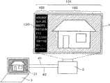
图1是本发明的一个实施例中的演示系统的框图。演示系统包括电子黑板装置1、由例如液晶投影仪构成的显示装置2、对系统整体进行控制的PC(也称为系统控制装置)3。电子黑板装置1与PC3例如通过USB(Universal Serial Bus,通用串行总线)等通信电缆40连接。电子黑板装置1通过它向PC3发送上述电子笔的位置坐标检测信息等信息。显示装置2与PC3通过影像电缆41连接,PC3对显示装置2发送用于显示的信息信号。此外,例如还基于RS-232C(Recommended Standard-232C)和LAN(Local Area Network,局域网络)标准,用通信电缆42连接,PC3控制显示装置2的动作。显示装置2基于PC3的控制,将显示图像光学地发送到电子黑板装置1,在其显示部上显示。Figure 1 is a block diagram of a demonstration system in one embodiment of the present invention. The presentation system includes an
电子黑板装置1的显示部101,包括说明用的显示图像的显示部102,和例如图标的显示部103。显示部102的显示和显示部103的显示,使用后述的显示装置2所具有的OSD(On Screen Display,屏上显示)功能合成。此处,作为一例,表示将显示部103设置在画面的左端侧的例子。显示部102上,如图所示显示着PC3的显示器31上显示的图像。该图像通过上述影像电缆41从PC3发送到显示装置2。The
位置坐标检测传感器110如上所述,以显示部101的每个像素或者每几个像素的精度检测电子笔(未图示)所指的位置,通过通信电缆40将位置信息发送到PC3。关于位置坐标检测传感器110,此处图示了配置在电子黑板装置1的左上、能够检测画面整体的位置坐标的结构,但也可以采用在显示部101的大致整个面上高密度地配置的结构。As described above, the positional coordinate
在显示部103上显示图标111。PC3中存储有用于使各图标显示不同图像的多个位图文件。此外,演示者通过在演示前操作PC3,能够预先设定每个图标的显示位置和是否显示。图标的显示位置,基于上述位置坐标检测传感器110所具有的位置信息设定。用于生成在显示部103上显示的图标的信息,包括上述位图文件和显示位置的信息在内,均通过PC3设定并登记在内部存储器中,进而通过上述通信电缆42从PC3供给到显示装置2。An
当演示者用电子笔指向图标111时,位置坐标检测传感器110例如通过压力或电磁波检测出所指的位置。将检测出的位置信息发送到PC3,由此PC3得知选择了哪一个图标,例如启动与其关联的程序。如果选择的图标是与PC3的操作相关的,则应用程序进行PC3的控制,如果是与显示装置2的操作相关的,则应用程序通过通信电缆42对显示装置2发送控制命令。When the demonstrator points to the
在显示部102上显示的图像和在显示部103上显示的图像,基于PC3的控制由显示装置2所含的OSD合成部合成,并在显示部101上显示。The image displayed on the
图2是现有的演示系统的框图。基于图2叙述现有例,一面对图1和图2进行比较一面说明本发明的特征。Fig. 2 is a block diagram of an existing demonstration system. The conventional example will be described based on FIG. 2 , and the features of the present invention will be described while comparing FIG. 1 and FIG. 2 .
图2中,对于与图1的构成元素同样的附加相同标记。图标112例如通过印刷在电子黑板装置1的画面的左端侧等来进行设置。显示装置2可以使说明用的显示图像避开该部分加以显示,但是因为图标112的位置固定,所以因设定状况可能会重叠。此外,也存在通过PC3在显示部102的内部设置图标组300并发送到显示装置2的情况。图标112固定设置,不能够切换显示的位置和是否显示。此外,图标组300能够在显示部102的范围内移动显示位置,但是因为与说明用的显示图像重叠,所以会妨碍演示参加者观看显示图像。In FIG. 2 , the same symbols are assigned to the same constituent elements as in FIG. 1 . The icon 112 is provided, for example, by printing on the left end side of the screen of the
图1所示的本实施例中,与图2的情况相比,具有以下特征。首先,从PC3所具有的应用程序将要显示的图标的位图文件和其在电子黑板装置1上的显示位置数据通过通信电缆42发送到显示装置2并加以存储。进而,使用显示装置2的OSD显示功能,在与说明用的显示图像的显示部102不重合的显示部103上,基于上述显示位置数据显示上述图标用的位图。Compared with the case of FIG. 2, the present embodiment shown in FIG. 1 has the following features. First, the bitmap file of the icon to be displayed and the display position data on the
此外,上述显示部103按如下方式所述确定。例如图1的显示部101的宽高比(横方向与纵方向的长度的比)与宽屏NTSC电视同样为16∶9,显示部102中的说明用的显示图像的宽高比与标准NTSC电视同样为4∶3(12∶9)的情况下,在显示部101的横方向上会产生空白区。图1是根据来自PC3的指示,显示装置2将空白区靠在显示部101的左端侧,设置显示部103并进行显示的情况。当然,也能够根据来自PC3的指示,将其靠在右端侧。此外,也可以如后文所述,在左端侧和右端侧双方加以设置,将显示部102靠在显示部101的中央部进行显示。In addition, the above-mentioned
因此,与图2的情况不同,本实施例中图标111与显示部102上显示的图像不会重叠,不会妨碍演示参加者观看图像。因为PC3能够对显示装置2指示各图标的显示位置,所以其排列顺序也能够按照便于演示者说明的方式预先设定。此外,各图标是否显示也能够由PC3来指示,所以也能够为了便于演示者说明而预设为将不需要的图标消去的状态。进而,根据电子黑板装置1位于演示会场的右侧还是左侧、演示者的惯用手在哪一边,演示者能够用PC3预设图标的显示部103是设置在显示部101的左端侧还是右端侧。由此,也能够解决演示者为了操作而移动位置从而妨碍演示顺利进行的问题。Therefore, unlike the case of FIG. 2 , in this embodiment, the
其中,关于图标的显示部103,说明了利用显示部101与说明用的显示图像的宽高比的不同而进行设置的情况,但是本实施例并不限定于此。也可以将图像在不会产生问题的范围内缩小显示,利用由此产生的空白区。此外,并不限定于设置在图像的左端侧或右端侧,例如也可以设置在上端侧或下端侧。即使是说明用的显示图像的显示部102中,也可以检测出没有文字信息、或者天空或水面等没有细节信息的图像部分,在此处设置图标。该情况下,可以具有对适合设置图标的部分进行自动判别的功能。由此,对演示参加者而言能够看到图标但又不会妨碍观看图像。In addition, the case where the
图3是本发明的一个实施例中的其他演示系统的框图。图3相对于图1,表示了将图标的显示部103设置在显示部101的左端侧和右端侧双方的情况。如上所述,这能够通过由PC3对显示装置2指示显示方法来实施。例如,如后文所述,可以将与PC3的操作关联的功能配置在左端侧,与显示装置2关联的功能配置在右端侧,由此演示者可以按照功能容易地搜寻到图标。Figure 3 is a block diagram of another presentation system in one embodiment of the present invention. FIG. 3 shows a case where the
其中,以上说明中举出电子黑板装置1为例作为显示出图像的装置,但本实施例的技术也能够对具有LCD(Liquid Crystal Display,液晶显示器)和PDP(Plasma Display Panel,等离子体显示面板)作为显示部的装置实施。也能够同样应用检测压力或检测电磁波的传感器作为用于检测电子笔的位置的位置坐标检测传感器。Wherein, in the above description, the
对于图1的图标111,也可以使其不仅对应与PC3的操作相关的功能,也可以对应用于使演示者操作显示装置2的功能。例如当使用显示的画面进行的说明暂时结束时,为了使演示参加者的关注集中于演示者,可能会暂时消去画面。此时,应当具有使包括液晶投影仪在内的显示装置2的照明光学系统熄灭,或者遮挡射向电子黑板装置1的光的功能。The
另外,因为图标111并不是像以往一样功能固定的,所以也能够通过扩展PC3的应用程序来进一步扩展图标111的功能。例如,当对显示装置2供给来自视频播放器(未图示)的动态再现图像的情况下,新设置用于选择该图像和从PC3供给的图像中的哪一个的图标。由此,也能够实现PC3控制显示装置2,以选择要在电子黑板装置1上显示的图像并加以显示的系统,能够进一步提高演示的效果。In addition, since the function of the
接着,用图4至图6说明本发明另外的其他实施例。图4是本发明的一个实施例的另一个其他演示系统的框图。此处与图1不同,显示部103不是图标111的显示区域,而是起到消息显示用的字符串显示区域120的作用。字符串显示区域120,具有预先准备的演示时的补足说明,和显示缩略词的正式名称等应用方法。此外,在演示中,演示者或其他操作者也能够操作PC3显示消息。虽然省略了位置坐标检测传感器110,但是在能够切换显示,如图1所示地显示图标111的系统中,也可以具备该位置坐标检测传感器110。通过PC3对显示装置2进行指示,能够随时在电子黑板装置1上显示任意内容的非固定的消息。当然,字符串显示区域120不限定于显示部101的左端侧,也可以设置在右端侧、上端侧或下端侧。此外,即使在说明用的显示图像的显示部102中,也可以使操作者能够通过PC3来选择是否重叠地显示字符串显示区域120。字符串的数据,例如是操作者利用PC3的键盘(未图示)输入的数据,或者在PC3包括的存储器中存储的数据,通过通信电缆42供给到显示装置2。根据需要,显示装置2也可以将从PC3供给的字符串的数据存储在内置的非易失性存储器中。Next, still another embodiment of the present invention will be described with reference to FIGS. 4 to 6 . Fig. 4 is a block diagram of another demonstration system of an embodiment of the present invention. Here, unlike FIG. 1 , the
但是,在液晶投影仪等显示装置2进行消息显示的情况下,会发生以下问题。对此,用图5和图6进行说明。图5是说明本发明的一个实施例中的显示方法的一个例子的图。图6是说明本发明的一个实施例中的显示方法的另一个例子的图。However, when a
考虑液晶投影仪等显示装置2的实际使用状态时,一般很少有从电子黑板装置1的正对面照射投影光的使用方法。普遍从演示参加者看来显示装置2不会造成妨碍的位置,例如斜下侧或斜上侧进行照射。此处,叙述水平方向从中央,高度方向从斜下侧对电子黑板装置1进行照射的情况。Considering the actual use state of the
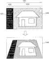
该情况下,在画面上越是显示在上部的部分放大率越大,显示图像中会产生变形。于是,显示装置2大多具有使要在电子黑板装置1的上部显示的图像缩小的变形修正功能。图5的两个图像中,上侧的图像表示对电子黑板装置1在水平方向、高度方向都从正对面照射投影光的情况下,显示装置2应当投影的图像,而下侧的图像表示仅高度方向从斜下侧照射的情况下应当投影的图像。图中的虚线表示在电子黑板装置1上对应的显示区域104。即,从斜下侧照射投影光的情况下,在显示装置2中,对于越靠上侧的图像,越使图像信号在画面的垂直方向和水平方向上缩小,由此能够进行变形修正。首先,通过减少扫描线等使垂直方向缩小,之后进行水平方向的处理,成为当从电子黑板装置1的正对面照射投影光时如图5下侧的图像所示显示为梯形的图像信号。由此,能够与图5上侧的图像同样地在显示区域104的整面上不产生变形地显示图像信号。有时将此称为梯形调整(keystone)显示。In this case, the higher the portion displayed on the screen, the higher the magnification, and distortion occurs in the displayed image. Therefore, the
不过,由于如后文详细叙述的那样对垂直方向进行了缩小,所以需要对消息显示进行重新的考虑。显示装置2中,首先对要在显示部102上显示的图像进行上述垂直方向的处理。之后,因为OSD合成的是规定尺寸的字符串,所以相对来说显示部103在垂直方向上比显示部102大。因此,本实施例中,在显示部102以规定的大小显示的基础上,减少在显示部103上显示的字符串的行数。此外,在因减少字符串而不能够完全显示消息的情况下,可以利用上述显示控制部使字符串在垂直方向上滚动显示,在每规定的时间内可以读取所有的字符串。However, since the vertical direction is reduced as described in detail later, it is necessary to reconsider the message display. In the
接着,图6与图5不同,表示显示装置2具有的电子缩放功能工作的情况。在以缩放比较高的状态显示图像的情况下,与图6上侧所示的缩放比为标准的情况相比,为了显示相同视角的图像,需要如图6下侧所示的垂直方向和水平方向都缩小了的图像信号。Next, FIG. 6 is different from FIG. 5 and shows a state in which the electronic zoom function of the
该情况下,本实施例中,将能够显示的字符串数和每一行的字符串数这两者都减小。与上述同样,不能够完全显示消息时,可以在垂直方向上滚动显示,在每规定的时间内可以读取所有的字符串。In this case, in this embodiment, both the number of character strings that can be displayed and the number of character strings per line are reduced. Similar to the above, when the message cannot be completely displayed, the display can be scrolled in the vertical direction, and all the character strings can be read every predetermined time.
使用图7,以OSD显示的情况为例,对以上用图5和图6叙述的事项进一步加以说明。图7是表示本发明的一个实施例中的变形修正与OSD显示的关系的图。Using FIG. 7, taking the case of OSD display as an example, the matters described above with reference to FIGS. 5 and 6 will be further described. FIG. 7 is a diagram showing the relationship between distortion correction and OSD display in one embodiment of the present invention.
图7中,600a表示显示装置2从电子黑板装置1的正对面投映时的图像。此处,在垂直方向的高度为a的部分,进行表示数字的OSD显示。从电子黑板装置1的斜下方投映的情况下,若实施上述变形修正,则在显示装置2向电子黑板装置1进行输出的输出部(例如相当于液晶投影仪中液晶面板上的图像)上成为600b所示的图像。即,如后文说明,显示装置2包括的图像处理部生成垂直方向缩小了的图像后,通过OSD合成处理部与规定大小(高度a)的OSD图像合成,然后由变形修正处理部根据垂直方向的位置使合成图像的水平方向缩小。In FIG. 7 , 600 a represents an image projected by the
在将该图像用显示装置2从斜下侧投映到电子黑板装置1时,相对放大率为图中600c中点划线601所示,所以从演示参加者看来,能够看到如图中600d所示的图像。即,成为修正了变形的图像。但是,比较600a与600d,OSD显示部分的高度成为图中的b,比原来的a变长。When the
接着,对于以上事项,用图8以在整个垂直方向上进行OSD显示的情况为例进行说明。之前图4所示的消息显示中,情况也是相同的。图8是另一表示本发明的一个实施例中的变形修正与OSD显示的关系的图。Next, the above matters will be described using FIG. 8 as an example in which the OSD display is performed in the entire vertical direction. In the previous message display shown in FIG. 4 , the situation is the same. FIG. 8 is another diagram showing the relationship between distortion correction and OSD display in an embodiment of the present invention.
图8中,602a表示显示装置2从电子黑板装置1的正对面投映的情况下的图像。此处,在画面左端侧整个垂直方向上,进行表示数字的OSD显示。从电子黑板装置1的斜下侧投映的情况下,实施上述变形修正,当将该图像用显示装置2从斜下侧投映到电子黑板装置1时,相对放大率如图中602b中的点划线601所示。若这样直接投映到电子黑板装置1,则图中的数字显示部分的上端部会处于电子黑板装置1的显示范围外。因此,利用显示装置2具有的OSD显示控制部减少显示的行数,如图中602c所示使上端部进入显示范围内。如果用于显示的行数不足,则可以如上所述进行滚动显示。另外,在图1和图3这样的显示部103中显示图标的实施例中,也可以考虑到实施上述变形修正而使图标部分处于电子黑板装置1的显示范围外的情况,但是该情况下可以利用显示装置2具有的OSD显示控制部来减少图标的显示间隔,使图标显示进入显示范围内。In FIG. 8 , 602 a represents an image when the
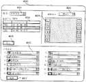
接着,回到如图1和图3这样的在显示部103上显示图标的情况,说明PC3中的要显示的图标的设定画面和设定方法。图9是表示本发明的一个实施例中的PC应用程序画面的一个例子的图。其示意性地表示了在图1的PC3所具有的显示器31上显示的PC应用程序窗口400的例子。能够考虑画面上的配置等与图9不同的例子,但都在本实施例的范畴内。Next, returning to the case where icons are displayed on the
PC应用程序窗口400内的机型选择列表401,例如由下拉菜单构成,当鼠标点击右端的箭头时,显示能够用PC3控制的显示装置2的机型一览表(未图示)。用户通过用鼠标从其中点击希望的机型来进行选择。于是,所选择的机型的连接目标显示在连接目标选择列表402中。此处表示显示了连接目标的名称和IP地址的例子。此处,用户选择的机型有3台,如果要使用其中连接目标“YYY”的显示装置,则用鼠标点击选择它。由此,PC3开始与用户选择的显示装置2进行信息的发送接收。The
接着进行图标的设定。此处,表示设定12种图标的例子。利用图标显示模式选择列表403的下拉菜单,用户选择希望的图标排列。如图所示,当选择模式1时,如图3所示,图标分开排列在电子黑板装置1的左端侧和右端侧。当选择模式2以下时,能够选择适合用户希望的图标排列:如图1所示图标集合排列在左端侧,或者用上端侧或下端侧排列图标。Then set the icon. Here, an example in which 12 types of icons are set is shown. Using the pull-down menu of the icon display
图中附加了数字1至12的图标显示模式404中,其功能通过功能选择列表405的功能设定来决定。此处,例如附加了数字1的图标显示模式404的功能,由功能选择列表405设为用于设定笔的粗细的图标。图中附加了数字1至12的功能选择列表405具有下拉菜单,用户从其中选择图标显示模式404的功能。例如能够将附加了数字1的图标显示模式404的功能变更为设定笔的颜色的图标。如果各功能与用于显示图标的位图文件一一对应,那么图标显示也会同时变更。图示的功能选择列表405中,表示了大多与PC3的控制相关的功能,但也可以包含上文叙述的显示装置2的显示ON/OFF(开/关)功能这样的与显示装置2相关的功能。In the
例如对附加了数字12的图标显示模式不进行功能设定时,在图中附加了数字12的功能选择列表中,从下拉菜单选择例如写有(无)的部分。此时,在电子黑板装置1的对应的显示部上不显示图标。此外,也能够将相同的图标显示模式设定在多个位置,将使用频率较高的图标例如同时配置在电子黑板装置1的左端侧和右端侧,改善演示者的易用性。For example, when the function setting is not performed for the icon display mode to which the
以上设定也能够在演示过程中进行,但通常事先预设。设定完成后,点击发送按键406,从而将与图标的选择、排列和功能相关的信息从PC3发送到显示装置2,存储在显示装置2具有的存储器中。此外,点击编辑按键407时,能够对功能选择列表405追加新的功能,或者编辑图标的位图图案。The above settings can also be made during the presentation, but are usually preset in advance. After the setting is completed, click the
接着,用图10说明从PC3发送到显示装置2并被存储的与图标的选择、排列和功能相关的信息的结构。图10是表示本发明的一个实施例中的图标信息的格式的图。Next, the structure of the information related to the selection, arrangement, and function of icons transmitted from the
图10中,1001表示各图标在电子黑板装置1上的显示位置。此处表示垂直方向和水平方向分开指定的例子。比特数会因扫描线数和显示像素数而改变,以能够获得规定精度的位置信息的方式选择。因为图标具有一定的大小,所以如果显示位置的信息具有像素精度,就可以在以指定的位置为中心的规定范围,或者以指定位置为例如左上端的规定范围内显示图标。如上所述,用电子笔指向图标时该图标的识别也可以用与此相同的方法使用位置信息来进行。In FIG. 10 , 1001 indicates the display position of each icon on the
1002是对相应的图标的位图文件附加的编号。例如如果位图文件在256种以内,则比特数为8比特即可。1003是与选择的图标对应的已编码的图标功能的信息。用户使用图9的功能选择列表405设定各图标的功能,由此设定各显示位置1001上的图标的位图和功能。1002 is a number added to the bitmap file of the corresponding icon. For example, if the number of bitmap files is within 256 types, the number of bits may be 8 bits. 1003 is the coded icon function information corresponding to the selected icon. The user sets the function of each icon using the
1004是表示电子黑板装置1上有无图标显示的信息,例如在图9的功能选择列表405中,如上所述设定在规定的位置不显示图标的情况下,通知该情况。如果已预先决定在没有指定图标功能1003的情况下不显示图标,则也可以不需要有无显示1004。1004 is information indicating whether or not an icon is displayed on the
如上所述,通过将图10所示的信息从PC3发送到显示装置2,能够控制电子黑板装置1上的图标的显示。As described above, by transmitting the information shown in FIG. 10 from the
接着,用图11说明显示装置2的结构。图11是本发明的一个实施例中的显示装置的框图。此处,包括图5所述的梯形调整显示的情况在内一并叙述。Next, the configuration of the
图11中,在输入端子200上连接有图1的影像电缆41,PC3所供给的说明用的显示图像的信息信号被输入显示装置2。输入的信号由输入处理部201接收,并输出到图像处理部202。图像处理部202中,进行之前用图5说明的用于梯形调整显示的处理的一部分。即,根据来自包含CPU(Central Processing Unit,中央处理单元)的控制部(也称为显示装置控制部)203的指示,进行减少扫描线数等处理,缩小垂直方向,作为进行变形修正的处理的一部分。其中,控制部203以相对于电子黑板装置1的投影角度为基础进行上述指示。图像处理部202中,还按照来自控制部203的指示,根据需要进行宽高比、缩放比和显示像素数的变换。图像处理部202的输出信号,被输入到OSD合成处理部207的一端,实施后文叙述的OSD合成。In FIG. 11 , the
接着,说明输入到OSD合成处理部207的另一端的信号。Next, signals input to the other end of the OSD
在输入输出端子211上连接有图1的通信电缆42,在PC3与显示装置2之间发送接收控制用的命令。之前用图9和图10说明的与图标显示相关的信息,也包括在其中进行供给。该与图标显示相关的信息,被通信处理部212分离并供给到控制部203,进而通过控制部203供给到OSD显示控制部206。此外,在ROM204中保存控制部203的OS(Operating System,操作系统)和应用程序,在RAM205中临时性地保存控制部203的动作中的信息。The
OSD显示控制部206中,基于通过控制部203供给的图标的位图和显示位置的信息,或者基于从内置的字体ROM供给的文字字体,对OSD合成部207的上述另一端供给用于在OSD合成部207中与之前的图像进行合成的图标和消息图像。In the OSD
对于OSD合成部207中合成的图像信号,进一步在变形修正处理部208中实施进行变形修正的处理的剩余一部分。即,根据垂直方向的位置缩小水平方向,变换为如图5所示的当从电子黑板装置1的正对面照射投影光时显示为梯形的图像信号。该缩小的程度根据来自控制部203的指示来确定。With respect to the image signal synthesized in the
变形修正处理部208的输出信号,在被面板驱动控制部209功率放大到能够充分驱动液晶面板210后,控制液晶面板210的透过度。众所周知,液晶面板210对于RGB三原色信号个别设置。此外,对液晶面板210,供给来自未图示的照明光学系统的投影光。透过液晶面板210的RGB三原色光,通过未图示的形成投影光学系统的透镜组照射到电子黑板装置1,显示图像。The output signal of the deformation
此处,用图12来说明图11的OSD显示控制部206的结构。图12是本发明的一个实施例中的显示装置的OSD显示部的框图。此处,叙述基于来自PC3的控制生成消息显示用的字符串的情况。Here, the configuration of the OSD
对OSD显示处理部206具有的OSD控制部230,从之前的控制部203输入与要显示的文字相关的信息。如图中所示,作为从PC3供给的二进制代码数据234输入。二进制代码数据234,具有表示对应的文字的数据,和表示显示位置的数据。在OSD控制部230,连接有字体ROM233。字体ROM233,具有各个二进制代码与文字的对应表235。OSD控制部230参照字体ROM233,将输入的各个二进制代码置换为文字的位图236,保存在RAM232中。例如如果二进制代码为4Eh,则保存文字N的位图。之后,OSD控制部230参照RAM232中保存的位图236,在OSD帧存储器231的与显示位置对应的场所进行描绘。描绘的结果的一个例子用图中的237表示。OSD帧存储器231中保存的数据通过OSD控制部230供给到之前的OSD合成处理部207的另一端。此时,OSD控制部230以从CPU203供给的例如相对于电子黑板装置1的投影角度的信息为基础,确定在电子黑板装置1上显示时的行数,或者同时确定缩放显示时的每一行的文字数。根据需要进行如上所述的滚动显示。另外,在进行如图1所示的图标显示的情况下,从PC3对显示装置2供给与图标的位图文件相关的信息,保存在RAM232中,并在OSD 帧存储器231中描绘。Information on characters to be displayed is input from the
接着,用图13,说明不用位置坐标检测传感器110,而用显示装置2具有的拍摄部(摄像头)进行电子笔指向的图标的判定的例子。图13是本发明的一个实施例中的其他显示装置的框图。与图11的情况不同,新设置了摄像头220和图像识别处理部221,在图像识别处理部221与控制部203之间发送接收控制信息。此外,在电子笔指向的图标与PC3的功能相关的情况下,控制部203通过通信处理部212和输入输出端子211,将检测信息发送到PC3。Next, with reference to FIG. 13 , an example in which determination of the icon pointed by the electronic pen is performed using the imaging unit (camera) included in the
摄像头220朝向映出显示装置2投影的图像的电子黑板装置1。演示者用电子笔指向图标时,基于摄像头220捕获的图像,图像识别处理部221检测出所指的图标,并通知控制部203。但是,即使对于从正对面的位置观看电子黑板装置1上映出的图像的演示参加者而言表现为如图5的上半部分所示的长方形的图像,在从正面斜下侧照射的显示装置2的位置观看的情况下,会表现为如图5的下半部分所示的梯形的图像。因此,为了根据摄像头220捕获的图像正确检测出电子笔指向的图标,需要进一步改进。The
本实施例中,图像识别处理部221以从控制部203供给的相对于电子黑板装置1的投影角度的信息为基础,求出摄像头220捕获的图标的本来位置,由此进行正确的图标检测。此外,在演示前例如用电子笔指向显示图像的角部(例如四角),用摄像头220捕获该影像,通过图像识别部221将位置信息通知控制部203。之后的演示中,基于该位置信息校正摄像头220捕获的各图标的位置,进行正确的图标检测。In this embodiment, the image recognition processing unit 221 calculates the original position of the icon captured by the
关于该事项,用图14详细说明。图14是说明本发明的一个实施方式中的影像的可视性的不同的图。This matter will be described in detail using FIG. 14 . FIG. 14 is a diagram illustrating a difference in visibility of video in one embodiment of the present invention.
首先,图中的500a,表示显示装置2对电子黑板装置1从正对面投影的情况。该情况下,演示参加者和显示装置2内置的摄像头220头都能够看到没有变形的长方形的图像。该情况下不会发生问题。First, 500a in the figure represents a situation where the
500b表示显示装置2对电子黑板装置1从斜下侧投影,演示参加者观看图像的情况。设图像为没有进行如上所述的变形修正的状态。图像的越靠上侧放大率越大,看起来为倒梯形的图像。但在显示装置2内置的摄像头220的位置观看相同的图像时,如500c所示看起来为与500a同样的长方形图像。因为摄像头220与显示装置2一体地移动,所以光轴保持平行,看起来仍然为长方形。500b indicates a state in which the
另一方面,在进行如上所述的变形修正,变换为如图500d所示的图像并投影的情况下,从显示装置2内置的摄像头220的位置观看时,看起来会成为如500d所示的梯形的图像。而对于演示参加者则会表现为如500e所示没有变形的长方形图像。On the other hand, when the distortion correction as described above is performed, and the image shown in FIG. 500d is converted and projected, when viewed from the position of the built-in
在图中的下部将500d的状态再次表示为500f。从摄像头220看来,演示者指向图中501的位置。501的位置位于图像的上部,但从图中虚线表示的摄像头220的视角看来,摄像头220检测出的是比实际更靠近中央的位置,所以会产生误差。于是,在演示前例如用电子笔指向502表示的图像的四角,存储由摄像头220检测出的位置信息,并与正确的位置信息比较并校正,由此进行正确的位置检测。由此,如500g所示,四角的位置被正确检测为503所示的位置。通过以相同比率进行与垂直方向和水平方向的位置相应的比例计算,能够得知之前的501表示的位置正确来说位于504表示的位置,进行正确的位置检测。这能够通过在显示装置2所含的图像识别部220中进行运算来实施。The state of 500d is again indicated as 500f in the lower part of the figure. From the perspective of the
如上所述,本实施例中,能够按用户的要求切换图标的显示位置。也能够选择取舍要显示的图标,或者引入新的功能。图标不会与演示中使用的图像重叠,在视觉上不会造成妨碍。不仅能够用图标进行PC的操作,还能够进行液晶投影仪等显示装置的操作。具有下述等效果:从正对面以外的位置投影时,即使进行变形修正也能够选择最佳的要显示的消息的行数,此外,在用显示装置内置的摄像头进行位置检测的情况下也能够正确地进行检测。As described above, in this embodiment, the display positions of icons can be switched according to the user's request. You can also choose which icons to display, or introduce new features. Icons do not overlap with images used in the demo and are not visually obstructive. Not only PC operations can be performed using icons, but also display devices such as liquid crystal projectors can be operated. It has the following effects: when projecting from a position other than the one directly opposite, the optimal number of lines of the message to be displayed can be selected even if the distortion correction is performed, and in the case of position detection using a camera built in the display device, it can also Check it out correctly.
以上表示的实施方式是一个例子,并不限定本发明。此外也可以考虑基于本发明的主旨但不同的实施方式,但都在本发明的范畴内。The embodiment shown above is an example and does not limit this invention. Furthermore, different embodiments based on the gist of the present invention are conceivable, but all are within the scope of the present invention.
Claims (11)
Translated fromChinesePriority Applications (1)
| Application Number | Priority Date | Filing Date | Title |
|---|---|---|---|
| CN201610035167.0ACN105549797B (en) | 2009-10-29 | 2010-10-29 | Display device and projection display device |
Applications Claiming Priority (2)
| Application Number | Priority Date | Filing Date | Title |
|---|---|---|---|
| JP2009248977AJP5442393B2 (en) | 2009-10-29 | 2009-10-29 | Display device |
| JP2009-248977 | 2009-10-29 |
Related Child Applications (1)
| Application Number | Title | Priority Date | Filing Date |
|---|---|---|---|
| CN201610035167.0ADivisionCN105549797B (en) | 2009-10-29 | 2010-10-29 | Display device and projection display device |
Publications (2)
| Publication Number | Publication Date |
|---|---|
| CN102053789Atrue CN102053789A (en) | 2011-05-11 |
| CN102053789B CN102053789B (en) | 2016-02-24 |
Family
ID=43663739
Family Applications (2)
| Application Number | Title | Priority Date | Filing Date |
|---|---|---|---|
| CN201610035167.0AActiveCN105549797B (en) | 2009-10-29 | 2010-10-29 | Display device and projection display device |
| CN201010530520.5AActiveCN102053789B (en) | 2009-10-29 | 2010-10-29 | Presentation system and display device for presentation system |
Family Applications Before (1)
| Application Number | Title | Priority Date | Filing Date |
|---|---|---|---|
| CN201610035167.0AActiveCN105549797B (en) | 2009-10-29 | 2010-10-29 | Display device and projection display device |
Country Status (4)
| Country | Link |
|---|---|
| US (4) | US9098195B2 (en) |
| EP (1) | EP2317761B1 (en) |
| JP (1) | JP5442393B2 (en) |
| CN (2) | CN105549797B (en) |
Cited By (8)
| Publication number | Priority date | Publication date | Assignee | Title |
|---|---|---|---|---|
| CN103186018A (en)* | 2011-12-27 | 2013-07-03 | 精工爱普生株式会社 | Projector, and method for controlling the projector |
| CN103325281A (en)* | 2012-03-23 | 2013-09-25 | 北京克强科技文化中心 | Electronic teaching system |
| CN103365413A (en)* | 2012-03-22 | 2013-10-23 | 株式会社理光 | Information processing device, computer-readable storage medium and projecting system |
| CN104035658A (en)* | 2013-03-08 | 2014-09-10 | 卡西欧计算机株式会社 | Display Apparatus And Display Method |
| CN105159631A (en)* | 2014-05-30 | 2015-12-16 | 纬创资通股份有限公司 | Electronic device using method, electronic device and electronic equipment |
| CN106164828A (en)* | 2014-04-01 | 2016-11-23 | 精工爱普生株式会社 | Bidirectional display method and bidirectional display device |
| CN106331667A (en)* | 2015-07-03 | 2017-01-11 | 夏普株式会社 | Image display device, image display control method, and image display system |
| CN107817924A (en)* | 2016-09-12 | 2018-03-20 | 精工爱普生株式会社 | The control method of display device and display device |
Families Citing this family (24)
| Publication number | Priority date | Publication date | Assignee | Title |
|---|---|---|---|---|
| JP5832119B2 (en)* | 2011-04-06 | 2015-12-16 | キヤノン株式会社 | Projection apparatus, control method thereof, and program |
| JP5997882B2 (en)* | 2011-07-21 | 2016-09-28 | セイコーエプソン株式会社 | Projector and projector control method |
| US8624934B2 (en)* | 2011-09-29 | 2014-01-07 | Microsoft Corporation | Dynamic display of icons on a small screen |
| KR101129221B1 (en) | 2011-10-19 | 2012-03-26 | 주식회사 한글과컴퓨터 | Presentation apparatus and presentation method of the presentation apparatus |
| JP5454722B2 (en)* | 2011-11-30 | 2014-03-26 | 株式会社リコー | Projector, display device, method and program |
| JP6106983B2 (en) | 2011-11-30 | 2017-04-05 | 株式会社リコー | Image display device, image display system, method and program |
| USD731511S1 (en)* | 2011-12-22 | 2015-06-09 | Maria Francisca Jones | Display screen with a graphical user interface computer icon |
| JP5924020B2 (en)* | 2012-02-16 | 2016-05-25 | セイコーエプソン株式会社 | Projector and projector control method |
| JP2014035573A (en)* | 2012-08-07 | 2014-02-24 | Ricoh Co Ltd | Information processor and program |
| JP6091133B2 (en)* | 2012-09-28 | 2017-03-08 | キヤノン株式会社 | Projection type display device, control method used therefor, and program |
| JP6565133B2 (en)* | 2014-04-01 | 2019-08-28 | セイコーエプソン株式会社 | Bidirectional display method and bidirectional display device |
| JP6364892B2 (en)* | 2014-04-01 | 2018-08-01 | セイコーエプソン株式会社 | Bi-directional projector and bi-directional projection method |
| JP6282919B2 (en)* | 2014-04-21 | 2018-02-21 | シャープ株式会社 | Touch panel integrated display device |
| USD813242S1 (en) | 2014-05-30 | 2018-03-20 | Maria Francisca Jones | Display screen with graphical user interface |
| JP2016014713A (en)* | 2014-07-01 | 2016-01-28 | 株式会社リコー | Image projection apparatus, image projection method, and control program for image projection apparatus |
| CN107077823B (en)* | 2014-09-16 | 2019-05-14 | 株式会社理光 | Display device, display system and display control program |
| GB2547682B (en) | 2016-02-25 | 2021-06-09 | Assa Abloy Ltd | A hinge |
| JP6897191B2 (en)* | 2017-03-17 | 2021-06-30 | セイコーエプソン株式会社 | Projector and projector control method |
| US20190132398A1 (en)* | 2017-11-02 | 2019-05-02 | Microsoft Technology Licensing, Llc | Networked User Interface Back Channel Discovery Via Wired Video Connection |
| CN109558062A (en)* | 2018-03-29 | 2019-04-02 | 广州小狗机器人技术有限公司 | A kind of determination method and apparatus of interactive placement |
| CN113056351B (en)* | 2018-11-01 | 2024-07-23 | 佳能株式会社 | External input device, robot system, control method thereof, and recording medium |
| CN111324325B (en)* | 2020-02-19 | 2023-11-07 | 京东方科技集团股份有限公司 | Display device, display method and electronic equipment |
| JP2022153986A (en)* | 2021-03-30 | 2022-10-13 | セイコーエプソン株式会社 | Display control method and display system |
| WO2022266998A1 (en)* | 2021-06-25 | 2022-12-29 | 京东方科技集团股份有限公司 | Intelligent interactive tablet and brightness adjustment method therefor |
Citations (8)
| Publication number | Priority date | Publication date | Assignee | Title |
|---|---|---|---|---|
| JP2004212488A (en)* | 2002-12-27 | 2004-07-29 | Matsushita Electric Ind Co Ltd | Projector screen device |
| CN1620100A (en)* | 2003-11-19 | 2005-05-25 | 三洋电机株式会社 | Image processing apparatus, image processing method, and image processing program |
| CN1937710A (en)* | 2005-09-22 | 2007-03-28 | 日本胜利株式会社 | Electronic device system |
| JP4079163B2 (en)* | 2005-05-30 | 2008-04-23 | ソニー株式会社 | Projection-type image display device |
| CN101395913A (en)* | 2005-06-02 | 2009-03-25 | 珀利维讯股份有限公司 | Virtual flip chart method and apparatus |
| US20090115722A1 (en)* | 2007-11-07 | 2009-05-07 | Omnivision Technologies, Inc. | Apparatus and method for tracking a light pointer |
| US7559656B2 (en)* | 2003-03-03 | 2009-07-14 | Panasonic Corporation | Projector system |
| WO2009108123A1 (en)* | 2008-02-29 | 2009-09-03 | Nanyang Polytechnic | Laser pointer based interactive display system and method thereof |
Family Cites Families (35)
| Publication number | Priority date | Publication date | Assignee | Title |
|---|---|---|---|---|
| EP0156752B1 (en)* | 1984-03-06 | 1988-09-28 | Constructions Electroniques de la Ferté sous Jouarre, S.A. | Control and surveillance system for emergency exits |
| JPH07298160A (en)* | 1994-04-25 | 1995-11-10 | Hitachi Ltd | Television device with built-in video CD player |
| GB9608770D0 (en)* | 1996-04-27 | 1996-07-03 | Philips Electronics Nv | Projection display system |
| JPH1185395A (en)* | 1997-09-08 | 1999-03-30 | Sharp Corp | LCD projector with pointing function |
| JP4252671B2 (en)* | 1999-05-21 | 2009-04-08 | セイコーエプソン株式会社 | Projection display |
| JP4541506B2 (en) | 2000-06-30 | 2010-09-08 | キヤノン株式会社 | Image processing apparatus, image processing method, and storage medium |
| JP4545895B2 (en) | 2000-07-17 | 2010-09-15 | キヤノン株式会社 | Image display device and display control method for image display device |
| US20060064716A1 (en)* | 2000-07-24 | 2006-03-23 | Vivcom, Inc. | Techniques for navigating multiple video streams |
| JP2002261918A (en)* | 2001-03-02 | 2002-09-13 | Hitachi Ltd | Mobile phone |
| JP2002366343A (en) | 2001-04-04 | 2002-12-20 | Sony Corp | Switcher for electronic white board and electronic white board system |
| GB0116805D0 (en)* | 2001-07-10 | 2001-08-29 | Britannic Overseas Trading Co | A human-computer interface with a virtual touch sensitive screen |
| JP2003276399A (en) | 2002-03-25 | 2003-09-30 | Matsushita Electric Ind Co Ltd | Position detecting method and device, and electronic blackboard device |
| US6898557B2 (en)* | 2002-05-17 | 2005-05-24 | Hewlett-Packard Development Company, Lp. | System and method for remote testing of components |
| US6963348B2 (en)* | 2002-05-31 | 2005-11-08 | Nvidia Corporation | Method and apparatus for display image adjustment |
| EP1385335B1 (en)* | 2002-07-23 | 2009-04-22 | NEC Display Solutions, Ltd. | Image projector with image-feedback control |
| JP2004212857A (en)* | 2003-01-08 | 2004-07-29 | Pioneer Electronic Corp | Touch panel display device |
| JP2005092592A (en)* | 2003-09-18 | 2005-04-07 | Nec Viewtechnology Ltd | Projector and projection system |
| US7125122B2 (en)* | 2004-02-02 | 2006-10-24 | Sharp Laboratories Of America, Inc. | Projection system with corrective image transformation |
| JP4214942B2 (en)* | 2004-04-13 | 2009-01-28 | セイコーエプソン株式会社 | projector |
| JP3960390B2 (en) | 2004-05-31 | 2007-08-15 | Necディスプレイソリューションズ株式会社 | Projector with trapezoidal distortion correction device |
| JP2006092269A (en)* | 2004-09-24 | 2006-04-06 | Hitachi Software Eng Co Ltd | Electronic board system |
| JP2006195771A (en)* | 2005-01-14 | 2006-07-27 | Seiko Epson Corp | Image display device |
| JP2007164561A (en)* | 2005-12-15 | 2007-06-28 | Sharp Corp | How to display the on-screen menu |
| JP4886300B2 (en)* | 2006-01-20 | 2012-02-29 | 株式会社東芝 | Projection type display device and OSD display method |
| JP2007279220A (en) | 2006-04-04 | 2007-10-25 | Sony Corp | Image display device |
| JP4860438B2 (en)* | 2006-11-07 | 2012-01-25 | 富士通株式会社 | Message display device, arithmetic device, message display program, and arithmetic program |
| US7770115B2 (en)* | 2006-11-07 | 2010-08-03 | Polycom, Inc. | System and method for controlling presentations and videoconferences using hand motions |
| JP4991458B2 (en)* | 2007-09-04 | 2012-08-01 | キヤノン株式会社 | Image display apparatus and control method thereof |
| JP4605478B2 (en)* | 2007-12-19 | 2011-01-05 | ソニー株式会社 | Information processing apparatus, display control method, and display control program |
| JP5147438B2 (en)* | 2008-02-05 | 2013-02-20 | キヤノン株式会社 | Output device, method and program |
| JP2009216815A (en)* | 2008-03-07 | 2009-09-24 | Sanyo Electric Co Ltd | Projection type video display device |
| JP5405047B2 (en)* | 2008-05-09 | 2014-02-05 | 三洋電機株式会社 | Projection display device |
| KR101537598B1 (en)* | 2008-10-20 | 2015-07-20 | 엘지전자 주식회사 | A portable terminal having a video projector and a control method thereof |
| US20100309391A1 (en)* | 2009-06-03 | 2010-12-09 | Honeywood Technologies, Llc | Multi-source projection-type display |
| JP4910062B2 (en)* | 2010-06-30 | 2012-04-04 | 株式会社東芝 | Stereoscopic image display device, stereoscopic glasses, and stereoscopic image display system |
- 2009
- 2009-10-29JPJP2009248977Apatent/JP5442393B2/enactiveActive
- 2010
- 2010-10-27USUS12/912,876patent/US9098195B2/enactiveActive
- 2010-10-28EPEP10014087.0Apatent/EP2317761B1/enactiveActive
- 2010-10-29CNCN201610035167.0Apatent/CN105549797B/enactiveActive
- 2010-10-29CNCN201010530520.5Apatent/CN102053789B/enactiveActive
- 2015
- 2015-07-02USUS14/790,685patent/US10373356B2/enactiveActive
- 2019
- 2019-06-25USUS16/451,400patent/US10950023B2/enactiveActive
- 2021
- 2021-02-10USUS17/172,487patent/US11625876B2/enactiveActive
Patent Citations (8)
| Publication number | Priority date | Publication date | Assignee | Title |
|---|---|---|---|---|
| JP2004212488A (en)* | 2002-12-27 | 2004-07-29 | Matsushita Electric Ind Co Ltd | Projector screen device |
| US7559656B2 (en)* | 2003-03-03 | 2009-07-14 | Panasonic Corporation | Projector system |
| CN1620100A (en)* | 2003-11-19 | 2005-05-25 | 三洋电机株式会社 | Image processing apparatus, image processing method, and image processing program |
| JP4079163B2 (en)* | 2005-05-30 | 2008-04-23 | ソニー株式会社 | Projection-type image display device |
| CN101395913A (en)* | 2005-06-02 | 2009-03-25 | 珀利维讯股份有限公司 | Virtual flip chart method and apparatus |
| CN1937710A (en)* | 2005-09-22 | 2007-03-28 | 日本胜利株式会社 | Electronic device system |
| US20090115722A1 (en)* | 2007-11-07 | 2009-05-07 | Omnivision Technologies, Inc. | Apparatus and method for tracking a light pointer |
| WO2009108123A1 (en)* | 2008-02-29 | 2009-09-03 | Nanyang Polytechnic | Laser pointer based interactive display system and method thereof |
Cited By (13)
| Publication number | Priority date | Publication date | Assignee | Title |
|---|---|---|---|---|
| CN106354343A (en)* | 2011-12-27 | 2017-01-25 | 精工爱普生株式会社 | Projector and method of controlling projector |
| CN103186018B (en)* | 2011-12-27 | 2016-08-31 | 精工爱普生株式会社 | Projector, and method for controlling the projector |
| CN103186018A (en)* | 2011-12-27 | 2013-07-03 | 精工爱普生株式会社 | Projector, and method for controlling the projector |
| CN106354343B (en)* | 2011-12-27 | 2019-01-08 | 精工爱普生株式会社 | The control method of projector and projector |
| CN103365413A (en)* | 2012-03-22 | 2013-10-23 | 株式会社理光 | Information processing device, computer-readable storage medium and projecting system |
| US9176601B2 (en) | 2012-03-22 | 2015-11-03 | Ricoh Company, Limited | Information processing device, computer-readable storage medium, and projecting system |
| CN103325281A (en)* | 2012-03-23 | 2013-09-25 | 北京克强科技文化中心 | Electronic teaching system |
| CN104035658A (en)* | 2013-03-08 | 2014-09-10 | 卡西欧计算机株式会社 | Display Apparatus And Display Method |
| CN106164828A (en)* | 2014-04-01 | 2016-11-23 | 精工爱普生株式会社 | Bidirectional display method and bidirectional display device |
| TWI645395B (en)* | 2014-04-01 | 2018-12-21 | 日商精工愛普生股份有限公司 | Two-way display method and two-way display device |
| CN105159631A (en)* | 2014-05-30 | 2015-12-16 | 纬创资通股份有限公司 | Electronic device using method, electronic device and electronic equipment |
| CN106331667A (en)* | 2015-07-03 | 2017-01-11 | 夏普株式会社 | Image display device, image display control method, and image display system |
| CN107817924A (en)* | 2016-09-12 | 2018-03-20 | 精工爱普生株式会社 | The control method of display device and display device |
Also Published As
| Publication number | Publication date |
|---|---|
| EP2317761B1 (en) | 2019-01-09 |
| EP2317761A3 (en) | 2013-03-06 |
| JP5442393B2 (en) | 2014-03-12 |
| US10950023B2 (en) | 2021-03-16 |
| CN105549797B (en) | 2018-08-31 |
| US11625876B2 (en) | 2023-04-11 |
| US10373356B2 (en) | 2019-08-06 |
| US20150302626A1 (en) | 2015-10-22 |
| JP2011097336A (en) | 2011-05-12 |
| CN102053789B (en) | 2016-02-24 |
| US20210166454A1 (en) | 2021-06-03 |
| EP2317761A2 (en) | 2011-05-04 |
| US20190311514A1 (en) | 2019-10-10 |
| US9098195B2 (en) | 2015-08-04 |
| CN105549797A (en) | 2016-05-04 |
| US20110107222A1 (en) | 2011-05-05 |
Similar Documents
| Publication | Publication Date | Title |
|---|---|---|
| CN102053789B (en) | Presentation system and display device for presentation system | |
| US6297804B1 (en) | Pointing apparatus | |
| CN102722289B (en) | Image supply device, image display system, method of controlling image supply device | |
| JP5082722B2 (en) | Image display device and image display system | |
| JP5488082B2 (en) | Information recognition system and control method thereof | |
| US20100149206A1 (en) | Data distribution system, data distribution apparatus, data distribution method and recording medium, improving user convenience | |
| CN107018391A (en) | The control method of image projection system, projecting apparatus and image projection system | |
| JP2013140533A (en) | Display device, projector, display system, and method of switching device | |
| JP2007017543A (en) | Presentation device, presentation system, presentation method, and presentation program | |
| US20130169671A1 (en) | Projector and method for controlling image display of the same | |
| JP3832132B2 (en) | Display system and presentation system | |
| CN107239177A (en) | Display system, display device, information processor and information processing method | |
| US7590662B2 (en) | Remote supporting apparatus, remote supporting system, remote supporting method, and program product therefor | |
| JP2017117020A (en) | Display device, display system, and method | |
| CN107731198B (en) | Display device and control method of display device | |
| CN104683717A (en) | Bidirectional display method and bidirectional display device | |
| JP5245805B2 (en) | Projector, control method therefor, and control program therefor | |
| JP2010272078A (en) | Electronic information board system, electronic information board control device, and cursor control method | |
| JP5755716B2 (en) | Display device and projection display device | |
| JP2009086082A (en) | Image display device and image display system | |
| JP2011126064A (en) | Display system, control method for display system, and projector | |
| JP2000172402A (en) | Image display device and computer-readable recording medium where program thereof is recorded | |
| JP7287156B2 (en) | Display device, display method, program | |
| JP4533078B2 (en) | Display control apparatus and display control method | |
| JP2006164222A (en) | System and method for recognizing and recording handwritten document by laser beam in real time |
Legal Events
| Date | Code | Title | Description |
|---|---|---|---|
| C06 | Publication | ||
| PB01 | Publication | ||
| C10 | Entry into substantive examination | ||
| SE01 | Entry into force of request for substantive examination | ||
| ASS | Succession or assignment of patent right | Owner name:HITACHI MAXELL LTD. Free format text:FORMER OWNER: HITACHI LTD. Effective date:20150302 | |
| C41 | Transfer of patent application or patent right or utility model | ||
| TA01 | Transfer of patent application right | Effective date of registration:20150302 Address after:Osaka Japan Applicant after:Hitachi Maxell, Ltd. Address before:Tokyo, Japan Applicant before:Hitachi Consumer Electronics Co.,Ltd. | |
| C14 | Grant of patent or utility model | ||
| GR01 | Patent grant | ||
| TR01 | Transfer of patent right | Effective date of registration:20180302 Address after:Kyoto Japan Patentee after:MAXELL, Ltd. Address before:Osaka Japan Patentee before:Hitachi Maxell, Ltd. | |
| TR01 | Transfer of patent right | ||
| CP01 | Change in the name or title of a patent holder | Address after:Kyoto Japan Patentee after:MAXELL, Ltd. Address before:Kyoto Japan Patentee before:MAXELL HOLDINGS, Ltd. | |
| CP01 | Change in the name or title of a patent holder | ||
| TR01 | Transfer of patent right | Effective date of registration:20220601 Address after:Kyoto Japan Patentee after:MAXELL HOLDINGS, Ltd. Address before:Kyoto Japan Patentee before:MAXELL, Ltd. | |
| TR01 | Transfer of patent right |