CN102053675B - Fixing mechanism and case applying same - Google Patents
Fixing mechanism and case applying sameDownload PDFInfo
- Publication number
- CN102053675B CN102053675BCN2009103090901ACN200910309090ACN102053675BCN 102053675 BCN102053675 BCN 102053675BCN 2009103090901 ACN2009103090901 ACN 2009103090901ACN 200910309090 ACN200910309090 ACN 200910309090ACN 102053675 BCN102053675 BCN 102053675B
- Authority
- CN
- China
- Prior art keywords
- fixed
- elastic component
- electronic device
- fixed mechanism
- base plate
- Prior art date
- Legal status (The legal status is an assumption and is not a legal conclusion. Google has not performed a legal analysis and makes no representation as to the accuracy of the status listed.)
- Expired - Fee Related
Links
Images


Classifications
- G—PHYSICS
- G06—COMPUTING OR CALCULATING; COUNTING
- G06F—ELECTRIC DIGITAL DATA PROCESSING
- G06F1/00—Details not covered by groups G06F3/00 - G06F13/00 and G06F21/00
- G06F1/16—Constructional details or arrangements
- G06F1/18—Packaging or power distribution
- G06F1/183—Internal mounting support structures, e.g. for printed circuit boards, internal connecting means
Landscapes
- Engineering & Computer Science (AREA)
- Theoretical Computer Science (AREA)
- Computer Hardware Design (AREA)
- Power Engineering (AREA)
- Human Computer Interaction (AREA)
- Physics & Mathematics (AREA)
- General Engineering & Computer Science (AREA)
- General Physics & Mathematics (AREA)
- Casings For Electric Apparatus (AREA)
Abstract
Translated fromChinese
Description
Translated fromChinese技术领域technical field
本发明涉及一种固定机构及采用该固定机构的机箱。The invention relates to a fixing mechanism and a cabinet adopting the fixing mechanism.
背景技术Background technique
机箱一般采用固定结构将电子装置,如计算机硬盘、光驱、软驱、电源等,固定于其机箱壳体内。The chassis generally adopts a fixed structure to fix electronic devices, such as computer hard disks, optical drives, floppy drives, power supplies, etc., in the chassis shell.
一种机箱,其包括机箱壳体及设于该机箱壳体上的固定机构,该固定机构用于将硬盘等电子装置固定于机箱壳体内。该固定机构包括及支架、固定于电子装置两侧的滑轨及螺丝。该支架上设有滑条,该滑轨可沿该滑条滑动。该每个滑轨的一端开设有一个螺孔。该滑条对应该滑轨的通孔开设有固定孔。该螺丝穿过该固定孔与螺孔,将该滑轨锁固于该滑条上,从而将该电子装置固定起来。A case includes a case shell and a fixing mechanism arranged on the case shell, and the fixing mechanism is used for fixing electronic devices such as a hard disk in the case shell. The fixing mechanism includes a bracket, slide rails and screws fixed on both sides of the electronic device. The bracket is provided with a slide bar, and the slide rail can slide along the slide bar. One end of each slide rail is provided with a screw hole. The slide bar is provided with a fixing hole corresponding to the through hole of the slide rail. The screw passes through the fixing hole and the screw hole, and the slide rail is locked on the slide bar, thereby fixing the electronic device.
然而,在更换或维修电子装置时,上述机箱的固定机构固定或拆卸该电子装置较繁锁。However, when replacing or maintaining the electronic device, it is cumbersome to fix or disassemble the electronic device by the above-mentioned fixing mechanism of the chassis.
发明内容Contents of the invention
鉴于上述状况,有必要提供一种固定或拆卸电子装置较方便的固定机构及采用该固定机构的机箱。In view of the above situation, it is necessary to provide a fixing mechanism which is more convenient for fixing or dismounting the electronic device and a case adopting the fixing mechanism.
一种固定机构,其用于固定电子装置,固定机构包括支架、固定于支架上的弹性件及设于电子装置的壳体上的定位部及配合部,支架上设有导向部,定位部沿导向部可滑动,弹性件上设有与配合部相卡持的卡合部,弹性件发生弹性形变,使卡合部与配合部分离。支架包括底板及从底板两相对侧基本垂直地朝向同一方向延伸的两侧板,弹性件固定于该底板上,导向部形成于该两个侧板上。A fixing mechanism, which is used to fix an electronic device. The fixing mechanism includes a bracket, an elastic member fixed on the bracket, and a positioning part and a matching part arranged on the housing of the electronic device. The guide part is slidable, and the elastic part is provided with a locking part which is locked with the matching part, and the elastic part is elastically deformed, so that the locking part is separated from the matching part. The bracket includes a bottom plate and two side plates extending from two opposite sides of the bottom plate substantially vertically toward the same direction, the elastic member is fixed on the bottom plate, and the guide portion is formed on the two side plates.
一种机箱,其包括机箱壳体及设于机箱壳体上的固定机构,固定机构用于电子装置固定于该机箱壳体上,该固定机构包括固定于该机箱壳体上的支架、固定于支架上的弹性件及设于电子装置壳体上的定位部及配合部,支架上设有导向部,定位部沿导向部可滑动,弹性件上设有与配合部相卡持的卡合部,弹性件发生弹性形变,使卡合部与配合部分离。支架包括底板及从底板两相对侧基本垂直地朝向同一方向延伸的两侧板,底板固定于该机箱壳体的一侧,侧板固定于该机箱壳体的另一相邻侧。弹性件固定于该底板上,该导向部形成于该两个侧板上。A case, which includes a case shell and a fixing mechanism arranged on the case shell, the fixing mechanism is used for fixing an electronic device on the case shell, and the fixing mechanism includes a bracket fixed on the case shell, fixed on the The elastic part on the bracket and the positioning part and the matching part arranged on the housing of the electronic device, the bracket is provided with a guiding part, the positioning part can slide along the guiding part, and the elastic part is provided with an engaging part which is clamped with the matching part , the elastic part undergoes elastic deformation, so that the engaging part is separated from the mating part. The bracket includes a bottom plate and two side plates extending from two opposite sides of the bottom plate substantially vertically toward the same direction, the bottom plate is fixed on one side of the case shell, and the side plate is fixed on the other adjacent side of the case shell. The elastic part is fixed on the base plate, and the guiding part is formed on the two side plates.
上述机箱的固定机构的卡合部与电子装置的配合部可分离地卡持,从而较方便地固定或拆卸电子装置。The engaging portion of the fixing mechanism of the case is detachably engaged with the mating portion of the electronic device, so that the electronic device can be fixed or disassembled more conveniently.
附图说明Description of drawings
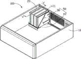
图1是本发明一实施例的装有电子装置的机箱开启一侧面板后的立体示意图。FIG. 1 is a schematic perspective view of a case with an electronic device installed therein with one side panel opened according to an embodiment of the present invention.
图2是图1所示的机箱与电子装置立体分解示意图。FIG. 2 is a three-dimensional exploded view of the case and the electronic device shown in FIG. 1 .
图3是图1所示的机箱的固定机构立体分解放大图。FIG. 3 is an exploded perspective view of the fixing mechanism of the chassis shown in FIG. 1 .
图4是图3所示的固定机构的另一视角的立体分解放大图。FIG. 4 is an exploded perspective view of another viewing angle of the fixing mechanism shown in FIG. 3 .
图5是图1所示的机箱沿V-V线的局部剖视图。Fig. 5 is a partial sectional view of the chassis shown in Fig. 1 along line V-V.
图6是图5所示的机箱的VI部分的放大示意图。FIG. 6 is an enlarged schematic view of part VI of the chassis shown in FIG. 5 .
图7是图1所示的机箱的VII部分的放大示意图。FIG. 7 is an enlarged schematic view of part VII of the chassis shown in FIG. 1 .
具体实施方式Detailed ways
下面结合附图及实施方式对本发明的固定机构及采用该固定机构的机箱作进一步详细说明。The fixing mechanism and the cabinet adopting the fixing mechanism of the present invention will be further described in detail below in conjunction with the accompanying drawings and embodiments.
请参阅图1,本发明较佳实施方式的机箱100包括机箱壳体10及设于机箱壳体10内的固定机构50。该固定机构50用于将电子装置20固定于机箱壳体10上,固定机构50包括固定于机箱壳体10上的支架30及设于支架30上的弹性件40。电子装置20可以是计算机的硬盘、光驱、软驱、电源等,在本实施方式中,以电源为例进行说明。Referring to FIG. 1 , a
请参阅图2及图6,机箱壳体10的一侧开设有开口11。固定机构100包括支架30及固定于支架30上的弹性件40。支架30对应于机箱壳体10的开口11设置,使电子装置20可从开口11装入支架30上。Please refer to FIG. 2 and FIG. 6 , an
电子装置20壳体的两相对侧面上分别设有多个定位部21,其相邻一侧设有多个配合部23(请参阅图6)。具体在实施方式中,定位部为固定于电子装置20壳体上的凸柱,配合部23为形成于电子装置20壳体上的卡合孔。A plurality of positioning
请同时参阅图3及图4,支架30为近似U型结构,其包括底板31及从底板31两相对侧基本垂直地朝向同一方向延伸的两侧板33。底板31位于两侧板33之间的侧边设有一向外侧延伸的的固定部311。固定部311固定于机箱壳体10一侧,两个侧板33固定于机箱壳体10的另一相邻侧。底板31的外表面上靠近固定部311的位置突出形成两个间隔的铆合柱314。该两个铆合柱314的连线方向基本垂直于两个侧板33。固定部311与两个铆合柱314之间还开设有两个矩形的通孔312。每个通孔312的位置与一个铆合柱314相对应。每个侧板33上形成有两个导向部331。电子装置20上的定位部21可沿导向部331滑动。具体在本实施方式中,导向部331为沿平行于底板31的方向延伸的导向槽。Please refer to FIG. 3 and FIG. 4 at the same time. The
弹性件40大致呈矩形片体,其一短边上设有按压部41,另一相邻长边上设有固定部42。按压部41从弹性件40一边折弯延伸,按压该按压部41,使弹性件40发生弹性形变。固定部41上开设有两个铆合孔421,支架31的铆合柱314穿过该铆合孔431,并将弹性件40铆合固定于支架30上,此时固定部42所在边的延伸方向与该定位部21的滑动方向基本垂直。弹性件40上远离固定部的一侧形成有卡合部43,卡合部43穿过支架30的底板31的通孔312,与电子装置20上的配合部23相卡合。具体在本实施方式中,卡合部43为凹陷形成于弹性件40上的凸包,该凸包上形成有与弹性件40基本垂直的阻挡部431,该阻挡部431与配合部23相抵持,从而阻止定位部21沿导向部331滑动。The
请同时参阅图4至图7,固定电子装置20时,将电子装置20从机箱壳体10的开口11装入,并使电子装置20的定位部21沿支架30的导向部331滑动到支架30上,直至弹性件30的卡合部43与电子装置20的配合部23相卡持,从而将电子装置20固定在支架30上。Please refer to FIG. 4 to FIG. 7 at the same time. When fixing the
拆卸电子装置20时,首先,按压弹性件30的按压部41,弹性件30发生弹性形变,使弹性件30的卡合部43与电子装置20的配合部23分离。然后,使电子装置20的定位部21沿支架30的导向部331朝向机箱壳体10的开口滑动,直至电子装置20完全从机箱壳体10的开口11退出。When disassembling the
上述固定机构100的弹性件40的卡合部43与电子装置20的配合部23可分离地卡持,从而较方便地固定或拆卸电子装置20。The
可以理解,弹性件40不限于采用铆合的方式固定在支架30上,其也可采用其它方式,例如,弹性件40可采用焊接的方式固定于支架30上。电子装置20的配合部23不限于卡合槽,其也可为其它结构,只需该结构可与弹性件40的卡合部43相卡持即可,例如,配合部23也可为卡钩。电子装置20的定位部21不限于定位凸柱,支架30的导向部331不限于导向槽,例如,电子装置20的定位部21也可为定位槽,此时支架30的导向部331为导向柱,导向柱可在定位槽内滑动。导向部331不限于沿平行于底板31的方向延伸的导向槽,其可为沿垂直于平行于底板31的方向延伸的导向槽,此时,卡合部43可为与配合部23相卡持的卡钩。It can be understood that the
另外,本领域技术人员还可在本发明精神内做其它变化,当然,这些依据本发明精神所做的变化,都应包含在本发明所要求保护的范围内。In addition, those skilled in the art can also make other changes within the spirit of the present invention. Of course, these changes made according to the spirit of the present invention should be included in the scope of protection claimed by the present invention.
Claims (8)
Priority Applications (2)
| Application Number | Priority Date | Filing Date | Title |
|---|---|---|---|
| CN2009103090901ACN102053675B (en) | 2009-10-30 | 2009-10-30 | Fixing mechanism and case applying same |
| US12/649,581US20110101832A1 (en) | 2009-10-30 | 2009-12-30 | Securing mechanism and electronic device enclosure using the same |
Applications Claiming Priority (1)
| Application Number | Priority Date | Filing Date | Title |
|---|---|---|---|
| CN2009103090901ACN102053675B (en) | 2009-10-30 | 2009-10-30 | Fixing mechanism and case applying same |
Publications (2)
| Publication Number | Publication Date |
|---|---|
| CN102053675A CN102053675A (en) | 2011-05-11 |
| CN102053675Btrue CN102053675B (en) | 2013-04-24 |
Family
ID=43924639
Family Applications (1)
| Application Number | Title | Priority Date | Filing Date |
|---|---|---|---|
| CN2009103090901AExpired - Fee RelatedCN102053675B (en) | 2009-10-30 | 2009-10-30 | Fixing mechanism and case applying same |
Country Status (2)
| Country | Link |
|---|---|
| US (1) | US20110101832A1 (en) |
| CN (1) | CN102053675B (en) |
Families Citing this family (4)
| Publication number | Priority date | Publication date | Assignee | Title |
|---|---|---|---|---|
| CN104181997A (en)* | 2013-05-23 | 2014-12-03 | 鸿富锦精密工业(深圳)有限公司 | Electronic device shell |
| CN103985401B (en)* | 2014-04-16 | 2017-02-01 | 深圳诺博医疗设备有限公司 | Case of smart medical cart |
| CN105759920B (en)* | 2016-04-29 | 2023-06-27 | 深圳市立尔讯科技有限公司 | Mounting structure of blade server |
| CN117135865A (en)* | 2022-05-18 | 2023-11-28 | 富联精密电子(天津)有限公司 | Bracket assembly and server assembly |
Citations (5)
| Publication number | Priority date | Publication date | Assignee | Title |
|---|---|---|---|---|
| CN2757207Y (en)* | 2004-11-15 | 2006-02-08 | 鸿富锦精密工业(深圳)有限公司 | Computer casing lid fixer |
| CN201035464Y (en)* | 2007-04-18 | 2008-03-12 | 刘泽彬 | Switch structure of side plate of case |
| CN101192084A (en)* | 2006-11-20 | 2008-06-04 | 英业达股份有限公司 | Cover Fixing Mechanism |
| CN101458549A (en)* | 2007-12-14 | 2009-06-17 | 鸿富锦精密工业(深圳)有限公司 | Computer cabinet |
| CN102043451A (en)* | 2009-10-23 | 2011-05-04 | 鸿富锦精密工业(深圳)有限公司 | Chassis |
Family Cites Families (17)
| Publication number | Priority date | Publication date | Assignee | Title |
|---|---|---|---|---|
| US5777848A (en)* | 1996-12-20 | 1998-07-07 | Dell Computer Corporation | Power supply mounting assembly for electronic equipment |
| TW427614U (en)* | 1999-05-15 | 2001-03-21 | Hon Hai Prec Ind Co Ltd | Case of electronic device |
| US6885550B1 (en)* | 1999-08-26 | 2005-04-26 | Axxion Group Corporation | Screw less clip mounted computer drive |
| US6373695B1 (en)* | 2000-09-22 | 2002-04-16 | Mace Tech Corp. | Mobile rack mounting structure for computer |
| US6392875B1 (en)* | 2000-12-28 | 2002-05-21 | Gateway, Inc. | Hinged mounting for multiple storage drives |
| TW515534U (en)* | 2001-05-18 | 2002-12-21 | Hon Hai Prec Ind Co Ltd | Apparatus for fixing data access device |
| US6768638B2 (en)* | 2001-12-14 | 2004-07-27 | Shoei-Yuan Shih | Server contained four juxtaposed hard disk drives |
| US6473313B1 (en)* | 2002-01-07 | 2002-10-29 | Hon Hai Precision Ind. Co., Ltd. | Fastening device for a securing data storage device |
| TW555045U (en)* | 2002-10-22 | 2003-09-21 | Hon Hai Prec Ind Co Ltd | Mounting device for storage device |
| TW587820U (en)* | 2002-11-15 | 2004-05-11 | Hon Hai Prec Ind Co Ltd | Securing device for storage device |
| US6853549B2 (en)* | 2003-03-14 | 2005-02-08 | Hon Hai Precision Ind. Co., Ltd | Mounting apparatus for data storage devices |
| TWM243692U (en)* | 2003-08-22 | 2004-09-11 | Hon Hai Prec Ind Co Ltd | Mounting apparatus for data storage device |
| CN2689318Y (en)* | 2004-02-27 | 2005-03-30 | 鸿富锦精密工业(深圳)有限公司 | Fixer of data access device |
| US7333329B2 (en)* | 2004-04-30 | 2008-02-19 | Hewlett-Packard Development Company, L.P. | Media drive containment apparatus and method |
| KR20070030032A (en)* | 2005-09-12 | 2007-03-15 | 삼성전자주식회사 | Computer |
| US7265972B2 (en)* | 2005-10-06 | 2007-09-04 | Lite-On Technology Corporation | Fixing mechanism for fixing a disc drive and a locking device thereof |
| CN2886750Y (en)* | 2005-12-23 | 2007-04-04 | 鸿富锦精密工业(深圳)有限公司 | Data memory fixing device |
- 2009
- 2009-10-30CNCN2009103090901Apatent/CN102053675B/ennot_activeExpired - Fee Related
- 2009-12-30USUS12/649,581patent/US20110101832A1/ennot_activeAbandoned
Patent Citations (5)
| Publication number | Priority date | Publication date | Assignee | Title |
|---|---|---|---|---|
| CN2757207Y (en)* | 2004-11-15 | 2006-02-08 | 鸿富锦精密工业(深圳)有限公司 | Computer casing lid fixer |
| CN101192084A (en)* | 2006-11-20 | 2008-06-04 | 英业达股份有限公司 | Cover Fixing Mechanism |
| CN201035464Y (en)* | 2007-04-18 | 2008-03-12 | 刘泽彬 | Switch structure of side plate of case |
| CN101458549A (en)* | 2007-12-14 | 2009-06-17 | 鸿富锦精密工业(深圳)有限公司 | Computer cabinet |
| CN102043451A (en)* | 2009-10-23 | 2011-05-04 | 鸿富锦精密工业(深圳)有限公司 | Chassis |
Also Published As
| Publication number | Publication date |
|---|---|
| CN102053675A (en) | 2011-05-11 |
| US20110101832A1 (en) | 2011-05-05 |
Similar Documents
| Publication | Publication Date | Title |
|---|---|---|
| US8550576B2 (en) | Chassis module for fixing electronic devices | |
| US7758308B2 (en) | Mounting apparatus for fan | |
| US7663875B2 (en) | Computer enclosure with airflow-guiding device | |
| TW201345373A (en) | Electronic device enclosure with locking structure | |
| CN103376848A (en) | Storage fixing device | |
| CN104345804A (en) | Fixed assembly | |
| CN201336009Y (en) | Buckling and fixing structure of disk driver | |
| CN107765785A (en) | Cabinet with tool-free opening device | |
| US20130220952A1 (en) | Mounting apparatus for hard disk drive | |
| CN103049057A (en) | Memory fixing device | |
| CN103853273A (en) | Electronic device and detachable assembly thereof | |
| CN102053675B (en) | Fixing mechanism and case applying same | |
| US8070243B2 (en) | Electronic device enclosure | |
| CN102809996A (en) | Magnetic rack rotation positioning device | |
| CN201319167Y (en) | Computer case | |
| US8199483B2 (en) | Optical disc drive retention assembly and electronic device utilizing the same | |
| CN103729033A (en) | Storage fixing device | |
| TW201401981A (en) | Mounting device for connector | |
| CN103857227A (en) | Electronic device shell | |
| TW201321935A (en) | Mounting apparatus for data storage device | |
| CN102312621B (en) | Locking device and electronic device with same | |
| CN103176543A (en) | Fixing device for data storage device | |
| CN102445966A (en) | data storage fixture | |
| TWI426856B (en) | Fixing mechanism and computer case using the same | |
| TW201301269A (en) | Fixing device for hard disk drive |
Legal Events
| Date | Code | Title | Description |
|---|---|---|---|
| C06 | Publication | ||
| PB01 | Publication | ||
| C10 | Entry into substantive examination | ||
| SE01 | Entry into force of request for substantive examination | ||
| C14 | Grant of patent or utility model | ||
| GR01 | Patent grant | ||
| CF01 | Termination of patent right due to non-payment of annual fee | Granted publication date:20130424 Termination date:20141030 | |
| EXPY | Termination of patent right or utility model |