CN102052592A - Dimmable LED lights - Google Patents
Dimmable LED lightsDownload PDFInfo
- Publication number
- CN102052592A CN102052592ACN2010101480722ACN201010148072ACN102052592ACN 102052592 ACN102052592 ACN 102052592ACN 2010101480722 ACN2010101480722 ACN 2010101480722ACN 201010148072 ACN201010148072 ACN 201010148072ACN 102052592 ACN102052592 ACN 102052592A
- Authority
- CN
- China
- Prior art keywords
- voltage
- bias
- switching
- led
- counter
- Prior art date
- Legal status (The legal status is an assumption and is not a legal conclusion. Google has not performed a legal analysis and makes no representation as to the accuracy of the status listed.)
- Granted
Links
Images


Classifications
- H—ELECTRICITY
- H05—ELECTRIC TECHNIQUES NOT OTHERWISE PROVIDED FOR
- H05B—ELECTRIC HEATING; ELECTRIC LIGHT SOURCES NOT OTHERWISE PROVIDED FOR; CIRCUIT ARRANGEMENTS FOR ELECTRIC LIGHT SOURCES, IN GENERAL
- H05B45/00—Circuit arrangements for operating light-emitting diodes [LED]
- H05B45/30—Driver circuits
- H05B45/37—Converter circuits
- H05B45/3725—Switched mode power supply [SMPS]
- H—ELECTRICITY
- H05—ELECTRIC TECHNIQUES NOT OTHERWISE PROVIDED FOR
- H05B—ELECTRIC HEATING; ELECTRIC LIGHT SOURCES NOT OTHERWISE PROVIDED FOR; CIRCUIT ARRANGEMENTS FOR ELECTRIC LIGHT SOURCES, IN GENERAL
- H05B47/00—Circuit arrangements for operating light sources in general, i.e. where the type of light source is not relevant
- H05B47/10—Controlling the light source
- H05B47/175—Controlling the light source by remote control
- H05B47/185—Controlling the light source by remote control via power line carrier transmission
- H—ELECTRICITY
- H05—ELECTRIC TECHNIQUES NOT OTHERWISE PROVIDED FOR
- H05B—ELECTRIC HEATING; ELECTRIC LIGHT SOURCES NOT OTHERWISE PROVIDED FOR; CIRCUIT ARRANGEMENTS FOR ELECTRIC LIGHT SOURCES, IN GENERAL
- H05B45/00—Circuit arrangements for operating light-emitting diodes [LED]
- H05B45/30—Driver circuits
- H05B45/37—Converter circuits
- H05B45/3725—Switched mode power supply [SMPS]
- H05B45/375—Switched mode power supply [SMPS] using buck topology
- H—ELECTRICITY
- H05—ELECTRIC TECHNIQUES NOT OTHERWISE PROVIDED FOR
- H05B—ELECTRIC HEATING; ELECTRIC LIGHT SOURCES NOT OTHERWISE PROVIDED FOR; CIRCUIT ARRANGEMENTS FOR ELECTRIC LIGHT SOURCES, IN GENERAL
- H05B45/00—Circuit arrangements for operating light-emitting diodes [LED]
- H05B45/30—Driver circuits
- H05B45/37—Converter circuits
- H05B45/3725—Switched mode power supply [SMPS]
- H05B45/382—Switched mode power supply [SMPS] with galvanic isolation between input and output
- H—ELECTRICITY
- H05—ELECTRIC TECHNIQUES NOT OTHERWISE PROVIDED FOR
- H05B—ELECTRIC HEATING; ELECTRIC LIGHT SOURCES NOT OTHERWISE PROVIDED FOR; CIRCUIT ARRANGEMENTS FOR ELECTRIC LIGHT SOURCES, IN GENERAL
- H05B45/00—Circuit arrangements for operating light-emitting diodes [LED]
- H05B45/30—Driver circuits
- H05B45/37—Converter circuits
- H05B45/3725—Switched mode power supply [SMPS]
- H05B45/385—Switched mode power supply [SMPS] using flyback topology
- Y—GENERAL TAGGING OF NEW TECHNOLOGICAL DEVELOPMENTS; GENERAL TAGGING OF CROSS-SECTIONAL TECHNOLOGIES SPANNING OVER SEVERAL SECTIONS OF THE IPC; TECHNICAL SUBJECTS COVERED BY FORMER USPC CROSS-REFERENCE ART COLLECTIONS [XRACs] AND DIGESTS
- Y02—TECHNOLOGIES OR APPLICATIONS FOR MITIGATION OR ADAPTATION AGAINST CLIMATE CHANGE
- Y02B—CLIMATE CHANGE MITIGATION TECHNOLOGIES RELATED TO BUILDINGS, e.g. HOUSING, HOUSE APPLIANCES OR RELATED END-USER APPLICATIONS
- Y02B20/00—Energy efficient lighting technologies, e.g. halogen lamps or gas discharge lamps
- Y02B20/30—Semiconductor lamps, e.g. solid state lamps [SSL] light emitting diodes [LED] or organic LED [OLED]
Landscapes
- Circuit Arrangement For Electric Light Sources In General (AREA)
Abstract
Description
Translated fromChinese技术领域technical field
本发明涉及一种发光二极管(Light-Emitting Diode;以下简称:LED)灯,且特别涉及一种发光二极管灯的多层次调光。The present invention relates to a light-emitting diode (Light-Emitting Diode; hereinafter referred to as: LED) lamp, and in particular to a multi-level dimming of a light-emitting diode lamp.
背景技术Background technique
照明调光器可节省能源,但由于安装不同类型的电子调光器需花费额外的成本,多数的白炽灯泡和省电灯泡,节能灯和新兴的发光二极管照明,皆不配备任何调光设施。在使用中,这些照明装置不是完全开启就是完全关闭的状态。在多数情况,为了安全上的考量,可将灯光调暗而非完全地关闭灯光是非常有必要的。例如在商场,商店,学校,医院,小型办公室,走廊,楼梯,工厂和仓库等场所,强烈地需要在下班后或夜间调暗部分的照明。Lighting dimmers can save energy, but due to the additional cost of installing different types of electronic dimmers, most incandescent bulbs and energy-saving bulbs, energy-saving lamps and emerging LED lighting are not equipped with any dimming facilities. In use, these lighting devices are either fully on or fully off. In most cases, it is necessary to dim the lights rather than completely turn them off for safety reasons. For example, in shopping malls, shops, schools, hospitals, small offices, corridors, stairs, factories and warehouses, there is a strong need to dim part of the lighting after get off work or at night.
三端双向可控硅开关调光器(Tri-electrode AC switch dimmer;以下简称:TRIAC dimmer)可改进单刀单掷(Single-Pole Single-Throw;以下简称:SPST)的墙壁开关而不需更换既有的墙壁开关布线系统,亦即没有重新布线的需求。三端双向可控硅开关调光器主要的工作方式为切断一部分的交流电压,使得其他部分的交流电压可传到灯泡。发光二极管灯的亮度决定于传输至其本身的能量多少而定,因此越多的交流电压被切断,发光二极管灯的亮度就越暗。Tri-electrode AC switch dimmer (hereinafter referred to as: TRIAC dimmer) can improve single-pole single-throw (Single-Pole Single-Throw; hereinafter referred to as: SPST) wall switch without replacing both There are wall switch wiring systems that do not require rewiring. The main working method of the triac dimmer is to cut off part of the AC voltage, so that the other part of the AC voltage can be transmitted to the bulb. The brightness of the LED lamp depends on how much energy is transferred to itself, so the more AC voltage is cut off, the dimmer the brightness of the LED lamp.
三端双向可控硅开关基本上为一直接操作于交流线路的三端固态元件。当一短路脉冲电流被注入闸极端时,三端交流开关为开启状态,也就是说,其可传输电流直至目前的半周期(half-cycle)结束。假设负载主要是电阻,例如使用白炽灯的情形下,当交流电压超过结束每半周期的零准位时,自负载电流降至零起,三端双向可控硅开关将重新开始其关闭状态(将其本身整流至关闭)。A triac is basically a three-terminal solid-state device that operates directly on the AC line. When a short-circuit pulse current is injected into the gate terminal, the triac is turned on, that is, it can transmit current until the end of the current half-cycle. Assuming that the load is primarily resistive, as in the case of an incandescent lamp, when the AC voltage exceeds the zero level that ends each half cycle, the triac will resume its off state since the load current drops to zero ( rectifies itself to off).
图1为一白炽灯泡10的传统三端双向可控硅开关调光电路20的示意图。三端双向可控硅开关调光电路20配置于单刀单掷的墙壁开关12和电源线AC1之间。电阻R23和电容C24决定交流线电压零交越(zero-crossing)后的延迟时间。其中电阻R23为一可变电阻。使用者可通过调节电阻R23的电阻值来控制前述的延迟时间。在三端双向可控硅开关25开启之前,除了小电流之外,基本上没有电流流经电阻R23而对电容C24充电。此小电流也流经白炽灯泡10,其中白炽灯泡10具有数百欧姆的电阻。在一延迟时间(决定于电阻R23、电容C24)后,电容C24的跨压已达到一足够高的值,例如30V以致使双向触发二极管(diac)26崩溃而进入一低电阻状态。双向触发二极管26的崩溃提供一短电流脉冲进入三端双向可控硅开关25的闸极端(GT),并开启三端双向可控硅开关25进入一传导状态。FIG. 1 is a schematic diagram of a conventional triac dimming circuit 20 for an incandescent light bulb 10 . The triac dimming circuit 20 is disposed between the
图2为图1的传统三端双向可控硅开关调光电路20中一些重要信号的示意图。如图2所示,通过增加延迟时间,可降低可控硅开关调光电路20的传导角

在开启三端双向可控硅开关25后,三端双向可控硅开关25的端点MT1、MT2上的跨压实质上降低至零。电容C24上的剩余电压经由电阻R23和三端双向可控硅开关25而被消除。值得注意的是,由于总是需要一些延迟时间使电容C24累积一些电荷以触发双向触发二极管26,因此最大传导角小于180度。After the
传统的三端双向可控硅开关调光器具有一些缺点。(1)使用三端双向可控硅开关调光器将降低灯具的功率因子。若调光器设定为非常暗的状态,灯具的功率因子可能低至0.20或是更低。Traditional triac dimmers have some disadvantages. (1) Using a triac dimmer will reduce the power factor of the lamp. If the dimmer is set to a very dark state, the power factor of the lamp may be as low as 0.20 or lower.
(2)由于在交流周期中突然开启三端双向可控硅开关,将使得三端双向可控硅开关调光器产生电磁干扰(Electro-Magnetic Interference;以下简称:EMI)与蜂音(buzzing sound)。通常一些电磁干扰滤波器的手段必须从增加和影响其它连接至同一布线系统的电气或电子装置的操作来制止电磁干扰噪声。图1画出了使用电容21和电感22的典型的电磁干扰滤波器。(2) Since the triac is suddenly turned on during the AC cycle, the triac dimmer will generate electromagnetic interference (Electro-Magnetic Interference; hereinafter referred to as: EMI) and buzzing sound ). Usually some means of EMI filter is necessary to stop EMI noise from adding to and affecting the operation of other electrical or electronic devices connected to the same wiring system. FIG. 1 shows a typical EMI filter using a capacitor 21 and an inductor 22 .
(3)三端双向可控硅开关调光器原本设计用以控制例如像白炽灯的电阻负载。白炽灯透过加热其钨丝至摄氏3000度以上以放射光线。切断一部份的交流电压对人眼来说不会出现闪烁的情形,因为即使当交流电压以60Hz/120Hz的频率脉动,灯丝温度也不会变动。然而,调暗灯光将使得白炽灯操作在较低的温度并发出微红的光线。(3) Triac dimmers were originally designed to control resistive loads such as incandescent lamps. Incandescent lamps radiate light by heating their tungsten filaments to over 3000 degrees Celsius. Cutting off a part of the AC voltage will not flicker to the human eye, because even when the AC voltage pulses at a frequency of 60Hz/120Hz, the temperature of the filament will not change. However, dimming the lights will cause incandescents to operate at a cooler temperature and emit a reddish glow.
(4)三端双向可控硅开关调光器通常不兼容于大多数的萤光灯和节能灯(Compact Fluorescent Lamp;以下简称:CFL)。三端双向可控硅开关调光器常导致灯泡闪烁或立即地损坏。事实上,萤光灯是出了名地难以调光。(4) Triac dimmers are usually not compatible with most fluorescent lamps and energy-saving lamps (Compact Fluorescent Lamp; hereinafter referred to as: CFL). Triac dimmers often cause bulbs to flicker or fail instantly. In fact, fluorescent lights are notoriously difficult to dim.
(5)三端双向可控硅开关调光器亦不兼容于大多数的发光二极管灯具。发光二极管只有当其传导顺偏电流才放射光线。只要电流一关掉,发光二极管便立即停止放射光线。因此当传导角小于90度时,通过三端双向可控硅开关调光器切断交流电压波形将导致可见的闪烁。(5) Triac dimmers are also not compatible with most LED lamps. A light emitting diode emits light only when it conducts a forward bias current. As soon as the current is turned off, the LED stops emitting light immediately. Thus, cutting off the AC voltage waveform through the triac dimmer will result in visible flicker when the conduction angle is less than 90 degrees.
图3为一使用红外线(infra-red,IR)远程控制系统的传统电子调光器之示意图。传导时间调节器31用以改变提供至灯泡35的功率。交流/直流电源供应电路32提供一直流电压至红外线接收器33和传导时间调节器31。红外线接收器33回应红外线遥控器36所发出的调光准位命令。值得注意的是,红外线遥控器36需要一电池供应操作电压以运行其内部电路。FIG. 3 is a schematic diagram of a conventional electronic dimmer using an infrared (infra-red, IR) remote control system. The transit time regulator 31 is used to vary the power supplied to the bulb 35 . The AC/DC power supply circuit 32 provides a DC voltage to the infrared receiver 33 and the conduction time regulator 31 . The infrared receiver 33 responds to the dimming level command sent by the infrared remote controller 36 . It should be noted that the infrared remote controller 36 requires a battery to supply operating voltage to operate its internal circuits.
电子调光器使用红外线或无线遥控不但可提供调光的功能也可提供其它复杂的控制功能,例如操作时间表。其可规避三端双向可控硅开关调光电路的限制并能帮助萤光灯和发光二极管灯的调光。但这些好处皆付出相当高的成本,包括:(a)增加红外线或无线接收器以及各灯泡的解码电路的额外成本。(b)遥控器单元需一些直流电压源,例如一电池。(c)控制器容易被放错地方、被滥用或被偷。Electronic dimmers use infrared or wireless remote control to provide not only dimming but also other complex control functions, such as operating schedules. It circumvents the limitations of triac dimming circuits and helps dimming fluorescent and light emitting diode lamps. But these benefits all pay quite high costs, including: (a) additional costs for adding infrared or wireless receivers and decoding circuits for each light bulb. (b) The remote control unit needs some DC voltage source, such as a battery. (c) Controllers can be easily misplaced, misused, or stolen.
发光二极管照明通常在一定电流的状态下操作。为了离线应用,降压转换器可用以转换整流交流电压为发光二极管灯所需的恒定直流电流。图4为一基于降压转换器的发光二极管照明驱动器40的示意图。发光二极管照明驱动器40包括一开关控制器50、一电感47、一续流二极管48(free-wheeling diode)、一功率金氧半场效晶体管45(Metal-Oxide-Semiconductor Field-Effect Transistor;以下简称:MOSFET)以及一电流感测电阻46。Light emitting diode lighting usually operates under a certain current state. For off-line applications, a buck converter can be used to convert the rectified AC voltage to the constant DC current required by LED lamps. FIG. 4 is a schematic diagram of a buck converter based
时脉产生器53通常运行在50kHz以上,当其发出一脉冲以设置SR正反器54(Flip-Flop)时,MOSFET 45开启。闸驱动器55放大SR正反器54的输出以驱动功率MOSFET 45。随着MOSFET 45开启,电流流经发光二极管灯49且电感47将其增强至更高的电流。发光二极管电流准位通过电流感测电阻46而得。当电流感测电阻46上的跨压超过参考电压VREF,比较器56重置正反器54的输出。MOSFET 45因此关闭。感应的发光二极管电流流经续流二极管48。电感电流开始衰减直到下个脉冲出现。通过高频率地重复开启与关闭MOSFET 45,发光二极管电流被控制在一由参考电压建立的稳定准位。
开关控制器50也包括一调光电路,其包括一调光锯齿波产生器51和一模拟比较器52。调光锯齿波产生器51通常产生100Hz至1kHz范围的脉冲宽度调变(Pulse-Width Modulation;以下简称:PWM)调光频率(亦即调光锯齿波)。调光电压VDIM可由图3所示的红外线接收器所提供。The
改变调光电压VDIM的准位可调整如图5所示的发光二极管驱动器的传导时间。图5为图4的发光二极管照明驱动电路中一些重要信号的示意图,从时间T1至时间T2,调光电压VDIM被设置在一高准位,例如4.5V。金氧半场效晶体管一直保持在开关模式(switching mode)。在时间T2之后,调光电压VDIM的准位降低至2.0V。当调光锯齿波提高至高于2.0V的电压准位,在时间T3时,模拟比较器52的输出变低。如此将使得及闸57抑制时脉产生器53设置正反器54。因此,MOSFET 45的开关操作将停止。Changing the level of the dimming voltage VDIM can adjust the conduction time of the LED driver shown in FIG. 5 . FIG. 5 is a schematic diagram of some important signals in the LED lighting driving circuit shown in FIG. 4 . From time T1 to time T2 , the dimming voltage VDIM is set at a high level, such as 4.5V. The MOSFET remains in switching mode all the time. After the time T2, the level of the dimming voltage VDIM is reduced to 2.0V. When the dimming sawtooth wave increases to a voltage level higher than 2.0V, at time T3, the output of the
在时间T4,锯齿波降低至零,且模拟比较器52的输出再度变高,致使时脉产生器53设置正反器54。值得注意的是,MOSFET 45在时间T2到T4期间(亦即MOSFET 45的开关责任周期)开关模式的责任周期比例为50%。在时间T4之后,调光电压VDIM的准位更降低至1.0V。类似地,在时间T4到T6期间MOSFET 45的开关责任周期为25%,使得调光电压VDIM准位进一步减少至0.5V,如此将会降低开关责任周期至12.5%。At time T4, the sawtooth wave drops to zero, and the output of the
偏压供应电路41包括一耦接至电感47的偏压绕组44(bias winding)。二极管43和电容42整流并缓和偏压绕组44产生的交流电压。当脉冲宽度调变调光周期性地抑制降压转换器的开关,电容42保持足够的电荷以维持降压转换器处于待机的状态。启动电阻连接于电压VDC与电容42之间。当交流电源一连接至发光二极管灯49和驱动电路时,电阻Rst帮助启动发光二极管照明驱动器40。The
然而,传统的调光控制方法使用三端双向可控硅开关元件或红外线遥控皆有一些缺点。三端双向可控硅开关调光器成本相对地较低且易于安装,但其性质无法兼容于发光二极管照明。另一方面,明显地其它调光机制的瓶颈在传输调光电压VDIM信息至发光二极管照明驱动器所需的额外的硬件和成本。However, traditional dimming control methods using triacs or infrared remote control have some disadvantages. Triac dimmers are relatively low cost and easy to install, but by their nature are not compatible with LED lighting. On the other hand, it is obvious that the bottleneck of other dimming mechanisms lies in the additional hardware and cost required to transmit the dimming voltage VDIM information to the LED lighting driver.
发明内容Contents of the invention
因此,本发明提供一种低成本、可调光的发光二极管灯。发光二极管灯不需对原本的墙壁开关进行任何重新布线或任何改造工作,不需可控硅调光器或任何额外的调光硬件,亦不需红外线或无线遥控器。发光二极管灯利用一平常的墙壁开关控制调光。整个调光的功能可内置于发光二极管灯的发光二极管照明驱动器。换言之,发光二极管灯可与相同规格外型的传统照明装置建构在一起,例如A19、PAR30、PAR38等。发光二极管灯在任何调光准位皆可维持非常高的功率因子(高于0.95)。Accordingly, the present invention provides a low cost, dimmable LED lamp. LED lights do not require any rewiring or any modification work to the original wall switch, no triac dimmers or any additional dimming hardware, and no infrared or wireless remote controls. LED lights are dimmed using a common wall switch control. The entire dimming function can be built into the LED lighting driver of the LED lamp. In other words, LED lamps can be constructed together with conventional lighting devices of the same specification and appearance, such as A19, PAR30, PAR38 and so on. LED lamps can maintain a very high power factor (higher than 0.95) at any dimming level.
本发明提出一种可调光的发光二极管灯,其包括一桥式整流器、一切换侦测器、一保持电压供应电路、一计数器、一发光二极管光源以及一发光二极管照明驱动器。桥式整流器经由墙壁开关接收交流电源电压并提供整流直流电压。切换侦测器监视墙壁开关的切换动作。保持电压供应电路提供保持电压。计数器接收保持电压以进行操作。此外,当切换侦测器侦测墙壁开关的切换动作时,计数器存储并提供变化的计数值。发光二极管照明驱动器转换整流直流电压为稳定电流以驱动发光二极管光源,并根据计数值提供发光二极管光源多层次的调光。The invention proposes a dimmable LED lamp, which includes a bridge rectifier, a switching detector, a holding voltage supply circuit, a counter, an LED light source and an LED lighting driver. A bridge rectifier receives AC mains voltage via a wall switch and provides a rectified DC voltage. Toggle detectors monitor the toggle action of wall switches. A sustain voltage supply circuit provides a sustain voltage. The counter receives a holding voltage for operation. In addition, when the toggle detector detects the toggle action of the wall switch, the counter stores and provides a changed count value. The LED lighting driver converts the rectified DC voltage into a stable current to drive the LED light source, and provides multi-level dimming of the LED light source according to the count value.
为让本发明的上述特征和优点能更明显易懂,下文特举实施例,并配合附图作详细说明如下。In order to make the above-mentioned features and advantages of the present invention more comprehensible, the following specific embodiments are described in detail with reference to the accompanying drawings.
附图说明Description of drawings
图1为一白炽灯泡的传统三端双向可控硅开关调光电路的示意图。FIG. 1 is a schematic diagram of a conventional triac dimming circuit for an incandescent light bulb.
图2为图1的传统三端双向可控硅开关调光电路中一些重要信号的示意图。FIG. 2 is a schematic diagram of some important signals in the traditional triac dimming circuit of FIG. 1 .
图3为一使用红外线远程控制系统的传统电子调光器的示意图。FIG. 3 is a schematic diagram of a conventional electronic dimmer using an infrared remote control system.
图4为一基于降压转换器的发光二极管照明驱动器的示意图。FIG. 4 is a schematic diagram of a buck converter based LED lighting driver.
图5为图4的发光二极管照明驱动电路中一些重要信号的示意图。FIG. 5 is a schematic diagram of some important signals in the LED lighting driving circuit shown in FIG. 4 .
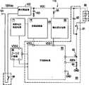
图6为本发明一实施例的具有墙壁开关控制调光功能的发光二极管灯的示意图。FIG. 6 is a schematic diagram of an LED lamp with a dimming function controlled by a wall switch according to an embodiment of the present invention.
图7为同样具有图6发光二极管灯的墙壁开关控制调光功能的发光二极管灯的示意图。FIG. 7 is a schematic diagram of an LED lamp that also has the dimming function controlled by the wall switch of the LED lamp in FIG. 6 .
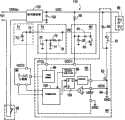
图8为图7的可调光发光二极管灯的较详细示意图。FIG. 8 is a more detailed schematic diagram of the dimmable LED lamp of FIG. 7 .
图9为图8的发光二极管灯的一些重要信号和操作的示意图。FIG. 9 is a schematic diagram of some important signals and operations of the LED lamp of FIG. 8 .
图10为图7与图8中另一种设计的开关控制器的示意图。FIG. 10 is a schematic diagram of another design of the switch controller shown in FIG. 7 and FIG. 8 .
主要元件符号说明:Description of main component symbols:
10:白炽灯泡 12:墙壁开关10: Incandescent light bulb 12: Wall switch
20:三端双向可控硅开关调光电 21、C24、42、72、103:电容路20: Triac dimming light 21, C24, 42, 72, 103: Capacitive circuit
22、47、81:电感 25:三端双向可控硅开关22, 47, 81: Inductance 25: Triac
26:双向触发二极管 31:传导时间调节器26: Bidirectional trigger diode 31: Conduction time regulator
32:交流/直流电源供应电路 33:红外线接收器32: AC/DC power supply circuit 33: Infrared receiver
35:灯泡 36:红外线遥控器35: Bulb 36: Infrared remote control
40、80:发光二极管照明驱动器 41:偏压供应电路40, 80: LED lighting driver 41: Bias supply circuit
43、73:二极管 44、93:偏压绕组43, 73: Diode 44, 93: Bias winding
45、83:功率金氧半场效晶体管 46:电流感测电阻45, 83: Power Metal Oxygen Half Field Effect Transistor 46: Current Sensing Resistor
48、82:续流二极管 49、60、110:发光二极管灯48, 82: Freewheeling
50、85:开关控制器 51、89:调光锯齿波产生器50, 85:
52:模拟比较器 53、88:时脉产生器52:
54:正反器 55:闸驱动器54: flip-flop 55: gate driver
56:比较器 57:及闸56: Comparator 57: And gate
61、99:发光二极管光源 62:散热片基板61, 99: LED light source 62: Heat sink substrate
63:驱动电路 64、98:墙壁开关63: Drive
71:保持电压供应电路 74:切换侦测器71: Hold voltage supply circuit 74: Switching detector
84:感测电阻 86:下降缘检测器84: Sense Resistor 86: Falling Edge Detector
87:数字模拟转换器 90:偏压供应电路87: Digital-to-analog converter 90: Bias supply circuit
78、91:整流二极管 75、92:滤波电容78, 91:
95:启动电阻 96:计数器95: Start resistor 96: Counter
101:交流线 102:桥式整流器101: AC line 102: Bridge rectifier
104:SR正反器 105:时脉跳跃电路104: SR flip-flop 105: Clock skipping circuit
VB:偏压交流电压 VDD1:偏压直流电压VB: Bias AC voltage VDD1: Bias DC voltage
VDD2:保持电压 VTGL:切换电压VDD2: Holding voltage VTGL: Switching voltage
VDC:整流直流电压 GND:接地VDC: rectified DC voltage GND: ground
ISEN:电流 MT1、MT2、GT:端点ISEN: Current MT1, MT2, GT: Endpoints
R23、Rst:电阻 AC1、AC2:电源线R23, Rst: Resistor AC1, AC2: Power cord
T0~T8:时间
VDIM:调光电压 VREF:参考电压VDIM: dimming voltage VREF: reference voltage
76、77:电阻分压器76, 77: Resistor divider
具体实施方式Detailed ways
下面将参考附图详细阐述本发明的实施例,附图举例说明了本发明的示范实施例,其中相同标号指示同样或相似的元件。Embodiments of the invention will now be described in detail with reference to the accompanying drawings, which illustrate exemplary embodiments of the invention, wherein like reference numerals indicate like or similar elements.
图6为本发明一实施例的具有墙壁开关控制调光功能的发光二极管灯60的示意图。发光二极管灯60包括发光二极管光源61、散热片基板62以及一驱动电路63。发光二极管光源61为安装在散热片基板62上的一串高亮度的发光二极管。驱动电路63转换交流电源为直流操作电流以驱动发光二极管光源61。驱动电路63包括一由墙壁开关64切换控制的调光电路。FIG. 6 is a schematic diagram of an
图7为同样具有图6发光二极管灯60的墙壁开关控制调光功能的发光二极管灯110的示意图。发光二极管灯110包括一桥式整流器102、一电容103、一启动电阻95、一偏压供应电路90、一切换侦测器74、一保持电压供应电路71、一计数器96、一发光二极管光源99以及一发光二极管照明驱动器80。桥式整流器102经由一墙壁开关98接收来自交流线101的交流电压源并提供一整流直流电压VDC。电容103过滤来自整流直流电压VDC的波纹及噪声。启动电阻95提供与图4的电阻Rst相同的用途。偏压供应电路90提供一偏压交流电压VB以及一偏压直流电压VDD1。发光二极管照明驱动器80接收偏压直流电压VDD1以进行操作。切换侦测器74监测墙壁开关98的切换动作。保持电压供应电路71提供一保持电压VDD2。在本实施例中,计数器96为一2比特计数器,其接收保持电压VDD2以进行操作,当切换侦测器74侦测墙壁开关98的切换动作时,计数器96存储并提供一变化的计数值。FIG. 7 is a schematic diagram of an
发光二极管照明驱动器80转换整流直流电压VDC为一稳定电流以驱动发光二极管光源99。发光二极管照明驱动器80根据计数器96所提供的计数值提供发光二极管光源99多层次的调光。The
发光二极管照明驱动器80包括一电感81,一续流二极管82(free-wheelingdiode),一功率金氧半场效晶体管83(metal-oxide-semiconductor field-effecttransistor,MOSFET),一感测电阻84以及一开关控制器85。电感81耦接至发光二极管光源99。续流二极管82具有一耦接至电感81的阳极以及一耦接至整流直流电压VDC以及发光二极管光源99的阴极。功率MOSFET 83耦接至电感81以及续流二极管82的阳极。感测电阻84耦接于功率MOSFET83与接地GND之间。
电感81、续流二极管82、功率MOSFET 83以及感测电阻84提供的功能与图4中相似的元件相同。发光二极管照明驱动器80为一降压转换器。当功率MOSFET 83开启时,电感81上的跨压为正。流经发光二极管光源99和电感81因此而增加。电流ISEN提供与图4中相同的反馈。当功率MOSFET 83关闭时,由于续流二极管82和发光二极管光源99之间的压降为定值,因此电感81上的跨压变为负。流经发光二极管光源99以及电感81的电流因此而减小。功率MOSFET 83的快速切换使流经发光二极管光源99的电流实质上为定值。开关控制器85接收偏压直流电压VDD1以进行操作。开关控制器85根据计数器96所提供的计数值,并通过控制功率MOSFET 83的开关责任周期来控制发光二极管光源99的多层次调光。
图8为图7的可调光发光二极管灯110的详细示意图。偏压供应电路90包括一偏压绕组93(bias winding),一整流二极管91以及一滤波电容92。电感81以及偏压绕组93经由一共同磁芯进行电磁耦合。当功率MOSFET 83切换时,跨越电感81的交流电压增强。如此将诱导偏压绕组93上的交流电压增加相称的交流电压。换言之,偏压绕组93通过接收来自电感81的能量提供偏压交流电压VB。整流二极管91整流偏压交流电压VB。滤波电容92过滤偏压交流电压VB中的输出波纹。过滤的结果存储于滤波电容92作为偏压直流电压VDD1,并提供至发光二极管照明驱动器80。如此一来,即使发光二极管照明驱动器80的切换操作在脉冲宽度调变调光模式中被暂停,开关控制器85仍可维持在一待机模式。当一开始墙壁开关98被开启时,整流直流电压VDC透过启动电阻95对滤波电容92进行充电。发光二极管照明驱动器80在偏压直流电压VDD1达到指定的准位时(例如5V或10V)启动。FIG. 8 is a detailed schematic diagram of the
切换侦测器74包括一组电阻分压器76、77,一整流二极管78以及一滤波电容75。整流二极管78整流偏压交流电压VB。电阻分压器76和77分压整流偏压交流电压VB。滤波电容75帮助过滤在以最小调光频率进行脉冲宽度调变调光时所造成的输出电压波纹。滤波电容75提供过滤的结果作为切换电压VTGL。切换侦测器74侦测偏压绕组93上偏压交流电压VB的存在(或不存在)与否。若墙壁开关98关闭一会儿,MOSFET 83的切换将停止。偏压绕组93不再提供能量(亦即偏压交流电压VB)至滤波电容75。横跨滤波电容75上的切换电压VTGL透过电阻分压器77在100微秒内放电至零。开关控制器85包括一下降缘检测器86,其用以接收并监测切换电压VTGL。当下降缘检测器86侦测到切换电压VTGL低于一预设门槛时,下降缘检测器86输出一触发信号至计数器96。计数器96改变计数值以对应触发信号开始逐次计数。The
保持电压供应电路71也接收来自偏压绕组93的能量。二极管73整流偏压交流电压VB。电容72过滤经整流的偏压交流电压VB中的输出波纹并提供过滤的结果作为保持电压VDD2。保持电压供应电路71用以支援计数器96。计数器96为一超低功率CMOS逻辑电路,通常使用小于1微安培的电流。电容72可让保持电压VDD2处于够高的状态以使计数器96在发光二极管照明驱动器80停止切换后维持其计数值至少2秒。开关控制器85的电流补偿通常为几毫安培,为二比特计数器96的数百倍。因此,必须利用二极管73防止开关控制器85自电容72抽取电流。The sustain
切换侦测器74可保持切换电压VTGL高于下降缘检测器86的预设门槛直到墙壁开关98关闭后的一第一持续时间结束。偏压供应电路90可提供偏压直流电压VDD1至开关控制器85直到墙壁开关98关闭后的一第二持续时间结束。保持电压供应电路71提供的保持电压VDD2可保持存储于计数器96的计数值直到墙壁开关98关闭后的一第三持续时间结束。其中,第二持续时间长于第一持续时间且第三持续时间长于第二持续时间。举例来说,第一、第二以及第三持续时间可分别为1毫秒、100毫秒以及2秒。因此,使用者可调整发光二极管灯110的调光准位,只要他/她在第二以及第三持续时间的时间间隔内关闭,然后再打开墙壁开关98。若上述时间间隔长于第三持续时间,计数器96由于缺乏保持电压VDD2而失去其计数值,且发光二极管灯110的调光准位将被重置至最初的准位。
开关控制器85包括一数字模拟转换器87(digital-to-analog converter;以下简称:DAC)。数字模拟转换器87转换计数器96的计数值为一调光电压VDIM。当计数值增加时,调光电压VDIM降低。通过类似图4中开关控制器50的一控制装置,开关控制器85驱动功率MOSFET 83以致功率MOSFET83的开关责任周期正比于调光电压VDIM。如此一来,当计数器96增加其计数值时,发光二极管照明驱动器80提供较少的能量至发光二极管光源99做为回应。The
虽然在本实施例中计数器96的计数值仅由二比特所组成,在本发明的其它实施例中计数值可包含更多比特,因而能支援更多调光准位并达到更细微的调光准位控制。Although the count value of the
除了下降缘检测器86和数字模拟转换器87之外,开关控制器85和发光二极管照明驱动器80的其他组成部分所提供的功能与图4中相似的元件相同。因此,开关控制器85和发光二极管照明驱动器80的其他组成部分在此不再重复讨论。Except for the falling
在本发明的变化实施例中,发光二极管照明驱动器80可为一脉冲宽度调变转换器或一脉冲频率调变(pulse-frequency modulation;以下简称:PFM)转换器。除此之外,发光二极管照明驱动器80可为拓扑结构的降压转换器、正向转换器(forward converter)或回扫转换器(flyback converter)。In a variant embodiment of the present invention, the
图9为图8的发光二极管灯的一些重要信号和操作的示意图,如图9所示,当墙壁开关98第一次对发光二极管灯110供电时,计数器96的计数值被清除为00。此00状态设置开关控制器85操作在100%的脉冲宽度调变调光准位,也就是说,发光二极管照明驱动器80完全未被抑制。FIG. 9 is a schematic diagram of some important signals and operations of the LED lamp in FIG. 8 . As shown in FIG. 9 , when the
每个墙壁开关98的连续切换导致计数器96开始逐次计数。在第一次切换后,计数值进入01状态。因此,功率MOSFET 83的开关责任周期减少至50%。第二次切换使计数值进入10状态,其对应的开关责任周期为20%。第三次切换使计数值进入11状态,其对应的开关责任周期为12.5%。第四次切换使计数值重回00状态,开关责任周期再次变为100%。Successive toggling of each
然而,若墙壁开关98被关闭许多秒,保持电压供应电路71所提供的保持电压VDD2将降低至一非常低的值以致使二比特的计数器96将失去其计数值。当墙壁开关98再度被开启时,计数器96将会重置计数值至00状态。发光二极管照明驱动器80将操作在100%的调光责任周期。However, if the
图10为图7与图8中另一种设计的开关控制器85的示意图。在图10中,开关控制器85包括一时脉产生器88以及一时脉跳跃电路105。时脉产生器88提供一时脉信号。时脉跳跃电路105根据计数器96所提供的计数值跳过时脉信号中的一些脉冲。其中被跳过的脉冲数随着计数值增加而增加。举例来说,当二比特的计数值为00时,时脉跳跃电路105不跳过任何时脉脉冲。当二比特的计数值为01时,时脉跳跃电路105在每批连续8个时脉脉冲中跳过4个脉冲。当二比特的计数值为10时,时脉跳跃电路105在每批连续8个时脉脉冲中跳过6个脉冲。当二比特的计数值为11时,时脉跳跃电路105在每批连续8个时脉脉冲中跳过7个脉冲。时脉跳跃电路105提供跳过的时脉信号至SR正反器104。在时脉信号中,每个未跳过的脉冲设置SR正反器104的输出并使功率MOSFET 83开关一次以作为反应。如此一来,图10中的开关控制器85可达到与图8中开关控制器85相同的功能。FIG. 10 is a schematic diagram of another design of the
除了发光二极管灯110,上述的本发明的实施例也提供一可调光的发光二极管照明装置。此可调光的发光二极管照明装置可包括上述在图7、图8和图10中的保持电压供应电路71、切换侦测器74、偏压供应电路90、发光二极管照明驱动器80以及计数器96。In addition to the
综上所述,本发明利用一低功率的计数器以存储所需的调光准位值。在发光二极管灯开始被启动后,调光准位接收墙壁开关切换次数的指示。此外,当墙壁开关作为切换动作的一部分而被暂时地关闭时,低功率的计数器被保持电压供应电路维持在主动(active)的状态。再者,保持电压供应电路接收来自偏压供应电路的偏压绕组的能量。如此,本发明可达成低成本的发光二极管照明调光控制。其只需要一切换侦测器、一保持电压供应电路以及一计数器,而这些元件皆可被轻易地被集成至传统的发光二极管灯驱动电路。To sum up, the present invention utilizes a low-power counter to store the required dimming level value. The dimming level receives an indication of the number of times the wall switch toggles after the LED lights start to be activated. Additionally, the low power counter is maintained in an active state by the hold voltage supply circuit when the wall switch is temporarily turned off as part of the switching action. Furthermore, the sustain voltage supply circuit receives energy from the bias winding of the bias supply circuit. In this way, the present invention can achieve low-cost light-emitting diode lighting dimming control. It only needs a switching detector, a holding voltage supply circuit and a counter, and these components can be easily integrated into a conventional LED lamp driving circuit.
虽然本发明已以实施例揭示如上,但是并不能用以限定本发明,任何本领域技术人员,在不脱离本发明的精神和范围内,当可作些许的更动与润饰,故本发明的保护范围当视所附的权利要求所界定者为准。Although the present invention has been disclosed as above with the embodiments, it can not be used to limit the present invention. Any person skilled in the art can make some changes and modifications without departing from the spirit and scope of the present invention. Therefore, the present invention The scope of protection shall prevail as defined by the appended claims.
Claims (9)
Translated fromChineseApplications Claiming Priority (2)
| Application Number | Priority Date | Filing Date | Title |
|---|---|---|---|
| US12/616,099US8294379B2 (en) | 2009-11-10 | 2009-11-10 | Dimmable LED lamp and dimmable LED lighting apparatus |
| US12/616,099 | 2009-11-10 |
Publications (2)
| Publication Number | Publication Date |
|---|---|
| CN102052592Atrue CN102052592A (en) | 2011-05-11 |
| CN102052592B CN102052592B (en) | 2012-09-26 |
Family
ID=43617993
Family Applications (1)
| Application Number | Title | Priority Date | Filing Date |
|---|---|---|---|
| CN2010101480722AExpired - Fee RelatedCN102052592B (en) | 2009-11-10 | 2010-04-02 | Dimmable LED lights |
Country Status (5)
| Country | Link |
|---|---|
| US (1) | US8294379B2 (en) |
| EP (1) | EP2320710A1 (en) |
| JP (1) | JP2011103285A (en) |
| CN (1) | CN102052592B (en) |
| TW (1) | TWI387396B (en) |
Cited By (13)
| Publication number | Priority date | Publication date | Assignee | Title |
|---|---|---|---|---|
| WO2012028091A1 (en)* | 2010-08-31 | 2012-03-08 | Byd Company Limited | Dimming controlling circuit for led |
| CN102958240A (en)* | 2011-08-19 | 2013-03-06 | 盛群半导体股份有限公司 | light source device and dimming control circuit thereof |
| TWI452937B (en)* | 2012-06-25 | 2014-09-11 | Richtek Technology Corp | Led control device for phase cut dimming system and control method thereof |
| TWI489908B (en)* | 2013-09-06 | 2015-06-21 | Macroblock Inc | Light emitting diode drive circuit |
| CN105423140A (en)* | 2014-09-15 | 2016-03-23 | 戴乐格半导体公司 | Dynamic Bleeder Current Control for LED Dimmers |
| CN106465501A (en)* | 2014-05-30 | 2017-02-22 | 飞利浦照明控股有限公司 | LED lighting circuit fed by current source |
| CN108445953A (en)* | 2018-05-30 | 2018-08-24 | 南宁市高照电器有限责任公司 | A kind of alternating current-direct current variable voltage source |
| CN108870107A (en)* | 2017-05-11 | 2018-11-23 | 广州市富胜照明灯具科技有限公司 | A kind of LED light of color-temperature regulating |
| TWI643528B (en)* | 2017-10-11 | 2018-12-01 | 茂達電子股份有限公司 | Adaptive backlight device, system and control method thereof |
| CN109417844A (en)* | 2016-05-24 | 2019-03-01 | 伊顿智能动力有限公司 | Lighting control based on switch |
| CN110169204A (en)* | 2017-05-27 | 2019-08-23 | 李玉麟 | Drive system |
| CN112664846A (en)* | 2016-01-22 | 2021-04-16 | 嘉兴山蒲照明电器有限公司 | Installation detection device, power module device and LED lamp using same |
| US11340640B2 (en) | 2018-05-03 | 2022-05-24 | Yu-Lin Lee | Driver circuit |
Families Citing this family (132)
| Publication number | Priority date | Publication date | Assignee | Title |
|---|---|---|---|---|
| US9253843B2 (en) | 2008-12-12 | 2016-02-02 | 02Micro Inc | Driving circuit with dimming controller for driving light sources |
| US9030122B2 (en) | 2008-12-12 | 2015-05-12 | O2Micro, Inc. | Circuits and methods for driving LED light sources |
| US9386653B2 (en) | 2008-12-12 | 2016-07-05 | O2Micro Inc | Circuits and methods for driving light sources |
| US9232591B2 (en) | 2008-12-12 | 2016-01-05 | O2Micro Inc. | Circuits and methods for driving light sources |
| CN102014540B (en) | 2010-03-04 | 2011-12-28 | 凹凸电子(武汉)有限公司 | Drive circuit and controller for controlling electric power of light source |
| US8508330B1 (en)* | 2009-05-25 | 2013-08-13 | Cypress Semiconductor Corporation | Adaptive filter for lighting assembly control signals |
| KR101020597B1 (en)* | 2010-03-03 | 2011-03-09 | 주식회사 라이트그린컨셉 | LED lighting driving device |
| CN103391006A (en) | 2012-05-11 | 2013-11-13 | 凹凸电子(武汉)有限公司 | Light source driving circuit and controller and method for controlling power converter |
| US8698419B2 (en) | 2010-03-04 | 2014-04-15 | O2Micro, Inc. | Circuits and methods for driving light sources |
| TWI501702B (en)* | 2010-04-23 | 2015-09-21 | Princeton Technology Corp | Method for adjusting light brightness using toggle switch and related illuminant system |
| JP2011249062A (en)* | 2010-05-25 | 2011-12-08 | Mitsumi Electric Co Ltd | Power supply controller for luminaire, and illumination system |
| CN102264175A (en)* | 2010-05-26 | 2011-11-30 | 马士科技有限公司 | Dimming device for light-emitting diode lamps with graded dimming |
| JP2011254665A (en)* | 2010-06-03 | 2011-12-15 | On Semiconductor Trading Ltd | Control circuit of light-emitting element |
| KR101124478B1 (en)* | 2010-06-25 | 2012-03-19 | 엘에스산전 주식회사 | dimming control apparatus for LED lighting system that being adjustable illuminance |
| US9625139B2 (en) | 2010-10-09 | 2017-04-18 | Autronic Plastics, Inc. | Modular LED lighting assembly |
| TWI466592B (en)* | 2010-11-08 | 2014-12-21 | Advanced Connectek Inc | Light-emitting element lamp circuit |
| US8866403B2 (en)* | 2010-12-09 | 2014-10-21 | General Electric Company | 3-way, phase-cut dimmable LED driver |
| US9018850B2 (en)* | 2010-12-28 | 2015-04-28 | GE Lighting Solutions, LLC | Safety flashing detector for traffic lamps |
| JP5110197B2 (en) | 2011-01-18 | 2012-12-26 | サンケン電気株式会社 | LED driving device and LED lighting device |
| JP2012227171A (en)* | 2011-01-18 | 2012-11-15 | Sanken Electric Co Ltd | Led driving device and led lighting apparatus |
| TW201236506A (en)* | 2011-02-24 | 2012-09-01 | Hanergy Technologies Inc | LED driver circuit |
| US8497636B2 (en)* | 2011-03-11 | 2013-07-30 | General Electric Company | Auto-switching triac compatibility circuit with auto-leveling and overvoltage protection |
| CN102791054B (en) | 2011-04-22 | 2016-05-25 | 昂宝电子(上海)有限公司 | For the system and method for the brightness adjustment control under capacity load |
| CN102395230B (en)* | 2011-05-04 | 2013-06-12 | 凹凸电子(武汉)有限公司 | Controller and method for controlling dimming of light sources, and light source driving circuit |
| US8598810B2 (en)* | 2011-05-05 | 2013-12-03 | Excelliance Mos Corporation | Constant current driving circuit of light emitting diode and lighting apparatus |
| CN102291882A (en)* | 2011-06-04 | 2011-12-21 | 魏其萃 | LED (Light Emitting Diode) drive circuit for replacing low-voltage AC (Alternating Current) incandescent lamp |
| CA2776185C (en)* | 2011-06-09 | 2016-11-15 | Osram Sylvania Inc. | Multiple channel light source power supply with output protection |
| JP5794835B2 (en)* | 2011-06-13 | 2015-10-14 | セミコンダクター・コンポーネンツ・インダストリーズ・リミテッド・ライアビリティ・カンパニー | Light emitting element drive circuit |
| US20140312776A1 (en)* | 2011-06-24 | 2014-10-23 | Planet System Co., Ltd. | Dimming led lighting system |
| TWI441428B (en)* | 2011-07-06 | 2014-06-11 | Macroblock Inc | Auto-selecting holding current circuit |
| KR101193305B1 (en)* | 2011-08-02 | 2012-10-19 | 삼성전기주식회사 | Dimming control device, apparatus for driving led, and dimming control method |
| KR101225106B1 (en) | 2011-08-18 | 2013-01-22 | 동서대학교산학협력단 | Self-generating shoes |
| US8692471B2 (en)* | 2011-09-15 | 2014-04-08 | Analog Devices, Inc. | LED driving system and method |
| CN102300375A (en)* | 2011-09-21 | 2011-12-28 | 缪仙荣 | Light emitting diode (LED) dimming circuit applicable to silicon controlled rectifier dimmer |
| CN103024974A (en)* | 2011-09-27 | 2013-04-03 | 台达电子工业股份有限公司 | Voltage induction type dimming control system and control method thereof |
| US9380657B2 (en) | 2011-10-04 | 2016-06-28 | Citizen Holdings Co., Ltd. | LED lighting device |
| US8704460B2 (en)* | 2011-11-07 | 2014-04-22 | Maxim Integrated Products, Inc. | LED current control in a dimmable LED illumination system |
| TW201325302A (en)* | 2011-12-02 | 2013-06-16 | Unity Opto Technology Co Ltd | LED driving device and method thereof |
| JP5947034B2 (en)* | 2011-12-20 | 2016-07-06 | ローム株式会社 | DC / DC converter and current driver control circuit, and light emitting device and electronic apparatus using the same |
| EP2632233B1 (en)* | 2012-02-22 | 2017-07-26 | Helvar Oy Ab | An apparatus for controlling the operation of an electronic ballast |
| JP6087960B2 (en) | 2012-03-09 | 2017-03-01 | フィリップス ライティング ホールディング ビー ヴィ | LED light source |
| TWI478626B (en)* | 2012-04-05 | 2015-03-21 | Paragon Sc Lighting Tech Co | Energy-saving illuminating apparatus and method thereof |
| CN102665327B (en)* | 2012-04-13 | 2014-08-06 | 江苏理工学院 | LED Power Supply for Transformerless Lighting |
| KR101376152B1 (en)* | 2012-04-23 | 2014-04-01 | 주식회사 에이디텍 | Led lighting apparatus |
| KR101377038B1 (en) | 2012-04-23 | 2014-03-20 | 주식회사 에이디텍 | LED lighting apparatus |
| US8581520B1 (en)* | 2012-05-14 | 2013-11-12 | Usai, Llc | Lighting system having a dimming color simulating an incandescent light |
| US8742695B2 (en) | 2012-05-14 | 2014-06-03 | Usai, Llc | Lighting control system and method |
| CN104768285B (en) | 2012-05-17 | 2017-06-13 | 昂宝电子(上海)有限公司 | System and method for carrying out brightness adjustment control using system controller |
| CN102769980B (en)* | 2012-07-25 | 2014-07-02 | 浙江大学 | Switch power source based power source voltage control device |
| TWI505644B (en)* | 2012-08-08 | 2015-10-21 | Leadtrend Tech Corp | Circuit with adjustable phase delay and a feedback voltage and method for adjusting phase delay and a feedback voltage |
| CN102958248B (en)* | 2012-08-16 | 2017-08-25 | 欧普照明股份有限公司 | A kind of LED illumination circuit |
| CN204721647U (en) | 2012-09-06 | 2015-10-21 | 莱弗实验室公司 | Lighting apparatus, user's computing equipment and the system for controlling illumination |
| CN103024994B (en) | 2012-11-12 | 2016-06-01 | 昂宝电子(上海)有限公司 | Use dimming control system and the method for TRIAC dimmer |
| TWI486736B (en)* | 2012-12-06 | 2015-06-01 | Yu Sheng So | Lighting control method and equipment |
| EP2747516A1 (en)* | 2012-12-18 | 2014-06-25 | Dialog Semiconductor GmbH | Circuit and method for detecting the duration of the interruption of a mains input |
| CN103090237A (en)* | 2013-01-31 | 2013-05-08 | 东莞市贺喜光电有限公司 | Light-emitting diode (LED) lamp without power supply unit |
| TWI504310B (en)* | 2013-02-07 | 2015-10-11 | Hep Tech Co Ltd | Dimming light emitting diode lighting system and its driving device and driving method |
| KR101576062B1 (en) | 2013-02-13 | 2015-12-09 | 신덴겐코교 가부시키가이샤 | Led illumination dimming circuit and led illumination dimming method |
| WO2014126258A1 (en) | 2013-02-18 | 2014-08-21 | シチズンホールディングス株式会社 | Led drive circuit |
| JP2014167856A (en)* | 2013-02-28 | 2014-09-11 | Toshiba Lighting & Technology Corp | Illuminating fixture |
| US8928255B2 (en)* | 2013-03-07 | 2015-01-06 | Osram Sylvania Inc. | Dynamic step dimming interface |
| AU2014232961B2 (en)* | 2013-03-15 | 2017-09-14 | Clear-Vu Lighting Llc | Task lighting system with alarm and dimming features |
| CN103167699A (en)* | 2013-03-28 | 2013-06-19 | 重庆大学 | A high stability visible light source |
| US9204505B2 (en)* | 2013-04-29 | 2015-12-01 | Stmicroelectronics, Inc. | Power converter for interfacing a fluorescent lighting ballast to a light emitting diode lamp |
| CN104135788B (en)* | 2013-05-02 | 2016-08-03 | 无锡华润华晶微电子有限公司 | A kind of constant current driver circuit for LED of tunable optical |
| US9608507B2 (en) | 2013-06-14 | 2017-03-28 | Sinope Technologies Inc. | Low power and low EMI power stealing circuit for a control device |
| TWM477112U (en)* | 2013-06-19 | 2014-04-21 | Wintek Corp | Illumination device power control module |
| EP2830395B1 (en)* | 2013-07-24 | 2017-09-13 | Dialog Semiconductor GmbH | Mains switch event detection for LED assemblies |
| US9992848B2 (en)* | 2013-08-01 | 2018-06-05 | Fong-Min Chang | Lighting control method and device |
| CN108601169B (en) | 2013-08-09 | 2020-01-10 | 意法半导体研发(深圳)有限公司 | Driving apparatus for light emitting device and method thereof |
| US10386027B1 (en) | 2013-09-13 | 2019-08-20 | Clear-Vu Lighting Llc | Pathway lighting system for tunnels |
| CN103533705B (en)* | 2013-09-18 | 2015-12-02 | 浙江生辉照明有限公司 | LED drives light adjusting circuit |
| US10047912B2 (en) | 2013-10-15 | 2018-08-14 | LIFI Labs, Inc. | Lighting assembly |
| GB2519794A (en)* | 2013-10-30 | 2015-05-06 | Kosnic Uk Ltd | Dimming lighting apparatus |
| CN104600964A (en)* | 2013-10-31 | 2015-05-06 | 通用电气公司 | Voltage adapter system used in device |
| US11455884B2 (en) | 2014-09-02 | 2022-09-27 | LIFI Labs, Inc. | Lighting system |
| US9198262B1 (en) | 2014-05-22 | 2015-11-24 | LIFI Labs, Inc. | Directional lighting system and method |
| US9210779B2 (en) | 2013-11-14 | 2015-12-08 | LIFI Labs, Inc. | Resettable lighting system and method |
| BE1021789B1 (en)* | 2013-11-25 | 2016-01-18 | Hoogenboom Special Products | LIGHTING ELEMENT |
| US10470263B2 (en)* | 2013-12-10 | 2019-11-05 | Ideal Industries Lighting Llc | Dimmable lighting systems and methods of dimming lighting systems |
| CN103697360A (en)* | 2013-12-31 | 2014-04-02 | 李忠训 | LED advertising lamp box back lighting lamp bar based on 220V alternating current |
| SG2014010839A (en)* | 2014-02-11 | 2015-09-29 | Opulent Electronics Internat Pte Ltd | Device and method for providing regulated current to an electrical load |
| JP6281764B2 (en)* | 2014-02-14 | 2018-02-21 | パナソニックIpマネジメント株式会社 | Lamp and lighting device |
| US9253854B2 (en)* | 2014-03-24 | 2016-02-02 | Crestron Electronics Inc. | Flicker compensation in lighting devices |
| CN103957634B (en) | 2014-04-25 | 2017-07-07 | 广州昂宝电子有限公司 | Lighting system and control method thereof |
| US9909748B2 (en) | 2014-05-02 | 2018-03-06 | Clear-Vu Lighting Llc | LED light fixture for use in public transportation facilities |
| CN106465499B (en) | 2014-05-22 | 2018-11-30 | 莱弗实验室公司 | Directional illumination system and method |
| US9686828B2 (en) | 2014-06-15 | 2017-06-20 | Lunera Lighting, Inc. | LED retrofit lamp with a strike barrier |
| US9826582B2 (en) | 2014-06-15 | 2017-11-21 | Lunera Lighting, Inc. | LED retrofit lamp with a strike barrier |
| CN104066254B (en) | 2014-07-08 | 2017-01-04 | 昂宝电子(上海)有限公司 | TRIAC dimmer is used to carry out the system and method for intelligent dimming control |
| US9326359B2 (en) | 2014-09-02 | 2016-04-26 | LIFI Labs, Inc. | Lighting system operation management method |
| US9648448B2 (en) | 2014-09-02 | 2017-05-09 | LIFI Labs, Inc. | Power outlet and method of use |
| US10015867B2 (en) | 2014-10-07 | 2018-07-03 | Curbell Medical Products, Inc. | Low-voltage controller with dimming function and method |
| ES2834633T3 (en)* | 2014-10-10 | 2021-06-18 | Xiaohua Luo | Counting device and LED drive unit activated by power cable edge signal |
| TWI558262B (en)* | 2015-01-28 | 2016-11-11 | 友達光電股份有限公司 | Light emitting diode driver |
| CN104640322B (en)* | 2015-02-06 | 2017-11-28 | 深圳市豪恩光电照明股份有限公司 | The LED lamp tube driver of compatible electronic ballast |
| AU2016218927A1 (en)* | 2015-02-09 | 2017-09-28 | Lumitech Pty Ltd | Dimmer system |
| JP6534119B2 (en)* | 2015-07-03 | 2019-06-26 | パナソニックIpマネジメント株式会社 | Dimmer |
| CN105072747B (en)* | 2015-07-30 | 2017-08-25 | 惠州市信迪节能环保科技有限公司 | A kind of LED drive circuit and LED lamp tube for being segmented adjusting power |
| US10394267B2 (en)* | 2015-09-04 | 2019-08-27 | Eaton Intelligent Power Limited | Electrical device, network and method of controlling the same |
| WO2017075296A1 (en) | 2015-10-27 | 2017-05-04 | ERP Power, LLC | Wall mounted ac to dc converter gang box |
| CN105423199A (en)* | 2015-11-27 | 2016-03-23 | 苏方宁 | Integrated frame type heat dissipation LED streetlamp |
| CN105423218A (en)* | 2015-12-08 | 2016-03-23 | 广东合即得能源科技有限公司 | a street light |
| WO2017139589A2 (en) | 2016-02-10 | 2017-08-17 | Hubbell Incorporated | Toggle control for lighting system |
| CN107635325A (en)* | 2016-07-18 | 2018-01-26 | 广州市新舞台灯光设备有限公司 | A kind of light of stage Intelligent Recognition automatic switching control system |
| AT519064A1 (en)* | 2016-08-22 | 2018-03-15 | Ing Michael Meth Dipl | Light source circuitry |
| CN106413189B (en) | 2016-10-17 | 2018-12-28 | 广州昂宝电子有限公司 | Use the intelligence control system relevant to TRIAC light modulator and method of modulated signal |
| US10440794B2 (en) | 2016-11-02 | 2019-10-08 | LIFI Labs, Inc. | Lighting system and method |
| CN206875378U (en) | 2016-12-23 | 2018-01-12 | 首尔半导体股份有限公司 | LED drivings system in package and the LED light device containing it |
| CN106555943A (en)* | 2017-01-19 | 2017-04-05 | 上海顿格电子贸易有限公司 | A kind of intelligent LED bulb |
| US10928046B2 (en) | 2017-05-05 | 2021-02-23 | Hubbell Incorporated | Light board for lighting fixture |
| TWI623243B (en)* | 2017-05-26 | 2018-05-01 | Conversion constant current LED driver | |
| CN107645804A (en) | 2017-07-10 | 2018-01-30 | 昂宝电子(上海)有限公司 | System for LED switch control |
| CN207399550U (en)* | 2017-07-20 | 2018-05-22 | 上海互兴科技股份有限公司 | Controllable silicon light modulation toning driving power circuit with memory function |
| CN107682953A (en) | 2017-09-14 | 2018-02-09 | 昂宝电子(上海)有限公司 | LED illumination System and its control method |
| JP2019087521A (en)* | 2017-11-02 | 2019-06-06 | 洋二 前田 | Led lighting device having light control function |
| CN107995730B (en) | 2017-11-30 | 2020-01-07 | 昂宝电子(上海)有限公司 | System and method for phase-based control associated with TRIAC dimmers |
| CN108200685B (en) | 2017-12-28 | 2020-01-07 | 昂宝电子(上海)有限公司 | LED lighting system for thyristor switch control |
| US10368412B2 (en) | 2017-12-29 | 2019-07-30 | Texas Instruments Incorporated | LED driver |
| US10426010B2 (en)* | 2017-12-29 | 2019-09-24 | Texas Instruments Incorporated | LED driver |
| US10443827B2 (en) | 2018-01-29 | 2019-10-15 | Clear-Vu Lighting Llc | Light fixture and wireway assembly |
| US10667358B1 (en) | 2018-03-13 | 2020-05-26 | Keith Bernard Marx | Load control using AC signalling with unique signatures |
| CN109922564B (en) | 2019-02-19 | 2023-08-29 | 昂宝电子(上海)有限公司 | Voltage conversion system and method for TRIAC drive |
| US11490474B1 (en) | 2019-03-29 | 2022-11-01 | Autronic Plastics, Inc. | Bi-level light fixture for public transportation tunnels |
| CN110493913B (en) | 2019-08-06 | 2022-02-01 | 昂宝电子(上海)有限公司 | Control system and method for silicon controlled dimming LED lighting system |
| CN110831295B (en) | 2019-11-20 | 2022-02-25 | 昂宝电子(上海)有限公司 | Dimming control method and system for dimmable LED lighting system |
| CN110831289B (en) | 2019-12-19 | 2022-02-15 | 昂宝电子(上海)有限公司 | LED drive circuit, operation method thereof and power supply control module |
| CN111031635B (en) | 2019-12-27 | 2021-11-30 | 昂宝电子(上海)有限公司 | Dimming system and method for LED lighting system |
| CN111432526B (en) | 2020-04-13 | 2023-02-21 | 昂宝电子(上海)有限公司 | Control system and method for power factor optimization of LED lighting systems |
| US11432385B2 (en) | 2020-08-07 | 2022-08-30 | Analog Devices, Inc. | Single comparator exponential-scale PWM dimming |
| CN114828331B (en)* | 2021-01-28 | 2025-07-11 | 漳州立达信光电子科技有限公司 | A dimming and color adjustment circuit, a dimming and color adjustment device and a lamp compatible with thyristor |
| US11864286B2 (en)* | 2021-11-03 | 2024-01-02 | ERP Power, LLC | Controlling LED channel current via hybrid DC and PWM reference signal |
Citations (3)
| Publication number | Priority date | Publication date | Assignee | Title |
|---|---|---|---|---|
| US7235933B1 (en)* | 2006-02-27 | 2007-06-26 | Yu-Sheng So | Reversible dimmer device of gas discharge lamps and the control method for light adjusting thereof |
| US20080297068A1 (en)* | 2007-06-01 | 2008-12-04 | Nexxus Lighting, Inc. | Method and System for Lighting Control |
| US20080316781A1 (en)* | 2007-06-21 | 2008-12-25 | Green Mark Technology Inc. | Buck converter led driver circuit |
Family Cites Families (63)
| Publication number | Priority date | Publication date | Assignee | Title |
|---|---|---|---|---|
| US3979601A (en) | 1975-02-10 | 1976-09-07 | Franklin Robert C | Combination dimmer and timer switch mechanism |
| US4253045A (en) | 1979-02-12 | 1981-02-24 | Weber Harold J | Flickering flame effect electric light controller |
| US4300090A (en) | 1979-03-02 | 1981-11-10 | Weber Harold J | Direct current power supply |
| US4344000A (en) | 1979-03-21 | 1982-08-10 | Dynascan Corporation | Power circuit control programmable timer |
| US4336464A (en) | 1979-05-10 | 1982-06-22 | Weber Harold J | Two terminal timed electric switch providing zero off-state current flow therethrough |
| US4439688A (en) | 1980-03-20 | 1984-03-27 | Dynascan Corporation | Electrical control apparatus |
| DE3023753C2 (en) | 1980-06-25 | 1986-06-26 | CENTRA-BÜRKLE GmbH, 7036 Schönaich | Circuit arrangement |
| US4494012A (en) | 1981-10-26 | 1985-01-15 | Intermatic Incorporated | Switch timer |
| US4504778A (en) | 1982-07-15 | 1985-03-12 | Electronic Systems International, Inc. | Self-powered, self-regulated, electronic ac control system |
| US4521843A (en) | 1982-08-16 | 1985-06-04 | Intermatic Incorporated | Programmable wall switch for controlling lighting times and loads |
| US4556863A (en) | 1982-12-06 | 1985-12-03 | Slater Electric Inc. | Emergency light switch |
| US4570216A (en) | 1983-02-10 | 1986-02-11 | Brightmond Company Limited | Programmable switch |
| US4649323A (en) | 1985-04-17 | 1987-03-10 | Lightolier Incorporated | Microcomputer-controlled light switch |
| US4695739A (en) | 1985-10-18 | 1987-09-22 | Pierce Lyle R | Multi-function switch-controlled lamp circuit |
| DE3537447A1 (en) | 1985-10-22 | 1987-04-23 | Diehl Gmbh & Co | SUPPLY CIRCUIT |
| US4730184A (en) | 1985-11-25 | 1988-03-08 | Arthur Bach | Neighborhood audio-visual alarm system |
| US4733138A (en) | 1985-12-05 | 1988-03-22 | Lightolier Incorporated | Programmable multicircuit wall-mounted controller |
| CA1271825A (en) | 1986-11-17 | 1990-07-17 | Brian E. Mcdonnell | Line voltage two wire thermostat |
| US4924109A (en) | 1987-11-02 | 1990-05-08 | Weber Harold J | Dim-down electric light time switch method and apparatus |
| US4878010A (en) | 1987-12-10 | 1989-10-31 | Weber Harold J | Electric a.c power switch controller and d.c. power supply method and apparatus |
| US5030890A (en) | 1988-05-25 | 1991-07-09 | Johnson Samuel A | Two terminal incandescent lamp controller |
| US4889999A (en) | 1988-09-26 | 1989-12-26 | Lutron Electronics Co., Inc. | Master electrical load control system |
| US5015994A (en) | 1989-12-28 | 1991-05-14 | Grh Electronics | Security light controlled by motion detector |
| JP2928359B2 (en) | 1990-09-07 | 1999-08-03 | 住友金属鉱山株式会社 | Indoor body presence detection device having door |
| US5081411A (en) | 1990-12-20 | 1992-01-14 | Honeywell Inc. | AC/DC two-wire control techniques |
| US5262678A (en) | 1991-06-21 | 1993-11-16 | Lutron Electronics Co., Inc. | Wallbox-mountable switch and dimmer |
| US5191265A (en) | 1991-08-09 | 1993-03-02 | Lutron Electronics Co., Inc. | Wall mounted programmable modular control system |
| US5586048A (en) | 1992-06-16 | 1996-12-17 | Vigilight Inc. | Intelligent wall switch |
| US5336979A (en) | 1992-11-12 | 1994-08-09 | Leviton Manufacturing Co., Inc. | Microprocessor based touch dimmer system to control the brightness of one or more electric lamps using single or multi-key devices |
| US5304781A (en) | 1992-11-24 | 1994-04-19 | Stalsberg Kevin J | Two terminal line voltage thermostat |
| US5283516A (en) | 1993-02-24 | 1994-02-01 | Pass & Seymour Legrand | Low voltage dimmer with no load protection |
| US5504394A (en) | 1993-03-08 | 1996-04-02 | Beacon Light Products, Inc. | Lamp bulb having integrated lighting function control circuitry and method of manufacture |
| US5373218A (en) | 1993-05-04 | 1994-12-13 | Motorola Lighting, Inc. | Toggle brightening circuit for powering gas discharge lamps and method for operating gas discharge lamps |
| US5430356A (en) | 1993-10-05 | 1995-07-04 | Lutron Electronics Co., Inc. | Programmable lighting control system with normalized dimming for different light sources |
| US5530301A (en) | 1994-06-06 | 1996-06-25 | Fu; Haizhong | Electronic delay turn off switch |
| US5473204A (en) | 1994-06-16 | 1995-12-05 | Temple; Thomas D. | Time delay switch |
| DE4441140A1 (en) | 1994-11-18 | 1996-05-30 | Hilite Lighting And Electronic | Dimming circuit for fluorescent lamps |
| US5872832A (en) | 1994-12-14 | 1999-02-16 | Bishel; Richard A. | Telephone-controlled electrical switch |
| US6356038B2 (en) | 1994-12-14 | 2002-03-12 | Richard A. Bishel | Microcomputer-controlled AC power switch controller and DC power supply method and apparatus |
| GB2308910A (en) | 1996-01-02 | 1997-07-09 | Bernard John Regan | Lighting control |
| US5736795A (en) | 1996-04-22 | 1998-04-07 | Honeywell Inc. | Solid state AC switch with self-synchronizing means for stealing operating power |
| JP3769815B2 (en)* | 1996-05-27 | 2006-04-26 | 松下電工株式会社 | Discharge lamp lighting device |
| US6225760B1 (en) | 1998-07-28 | 2001-05-01 | Lutron Electronics Company, Inc. | Fluorescent lamp dimmer system |
| US6700333B1 (en) | 1999-10-19 | 2004-03-02 | X-L Synergy, Llc | Two-wire appliance power controller |
| US6759966B1 (en) | 2000-09-01 | 2004-07-06 | Linsong Weng | Wireless remote control bulb device |
| US6490174B1 (en) | 2001-06-04 | 2002-12-03 | Honeywell International Inc. | Electronic interface for power stealing circuit |
| US6839165B2 (en) | 2001-08-03 | 2005-01-04 | Lutron Electronics Co., Inc. | Dimmer control system having remote infrared transmitters |
| JP4211022B2 (en)* | 2001-11-21 | 2009-01-21 | 三菱電機株式会社 | Discharge lamp lighting device |
| JP4547269B2 (en) | 2002-12-19 | 2010-09-22 | コーニンクレッカ フィリップス エレクトロニクス エヌ ヴィ | How to configure a wirelessly controlled lighting system |
| US6933686B1 (en) | 2003-01-09 | 2005-08-23 | Richard Anthony Bishel | Programmable AC power switch |
| JP2004311370A (en)* | 2003-04-02 | 2004-11-04 | Hitachi Lighting Ltd | Lighting control system |
| US7012518B2 (en) | 2003-04-18 | 2006-03-14 | Cooper Wiring Devices, Inc. | Dimmer control system with two-way master-remote communication |
| US7211968B2 (en) | 2003-07-30 | 2007-05-01 | Colorado Vnet, Llc | Lighting control systems and methods |
| US7355523B2 (en) | 2004-04-15 | 2008-04-08 | Alberto Sid | Remote controlled intelligent lighting system |
| US7190125B2 (en)* | 2004-07-15 | 2007-03-13 | Lutron Electronics Co., Inc. | Programmable wallbox dimmer |
| US7476988B2 (en) | 2005-11-23 | 2009-01-13 | Honeywell International Inc. | Power stealing control devices |
| US7579717B2 (en)* | 2006-09-13 | 2009-08-25 | Lutron Electronics Co., Inc. | Wall-mountable timer for an electrical load |
| TWM325440U (en)* | 2007-05-01 | 2008-01-11 | Jia-Jang Lin | Electric compact lamp dimmer control gear |
| JP4450019B2 (en) | 2007-07-03 | 2010-04-14 | ソニー株式会社 | Control device and control method, and planar light source device and planar light source device control method |
| JP5231030B2 (en) | 2007-08-20 | 2013-07-10 | 三菱電機株式会社 | Lighting device, lighting state display device, and lighting fixture |
| US20090058323A1 (en)* | 2007-08-30 | 2009-03-05 | Ta-Yung Yang | Flyback LED drive circuit with constant current regulation |
| JP2009259489A (en)* | 2008-04-14 | 2009-11-05 | Mitsubishi Electric Corp | Display device and illumination system |
| US8183798B2 (en)* | 2009-10-05 | 2012-05-22 | Hubbell Incorporated | Variable light control system and method using momentary circuit interrupt |
- 2009
- 2009-11-10USUS12/616,099patent/US8294379B2/ennot_activeExpired - Fee Related
- 2009-12-14EPEP09179099Apatent/EP2320710A1/ennot_activeWithdrawn
- 2010
- 2010-02-08JPJP2010025142Apatent/JP2011103285A/enactivePending
- 2010-03-15TWTW099107471Apatent/TWI387396B/ennot_activeIP Right Cessation
- 2010-04-02CNCN2010101480722Apatent/CN102052592B/ennot_activeExpired - Fee Related
Patent Citations (3)
| Publication number | Priority date | Publication date | Assignee | Title |
|---|---|---|---|---|
| US7235933B1 (en)* | 2006-02-27 | 2007-06-26 | Yu-Sheng So | Reversible dimmer device of gas discharge lamps and the control method for light adjusting thereof |
| US20080297068A1 (en)* | 2007-06-01 | 2008-12-04 | Nexxus Lighting, Inc. | Method and System for Lighting Control |
| US20080316781A1 (en)* | 2007-06-21 | 2008-12-25 | Green Mark Technology Inc. | Buck converter led driver circuit |
Cited By (20)
| Publication number | Priority date | Publication date | Assignee | Title |
|---|---|---|---|---|
| US8901836B2 (en) | 2010-08-31 | 2014-12-02 | Shenzhen Byd Auto R&D Company Limited | Dimming controlling circuit for LED |
| WO2012028091A1 (en)* | 2010-08-31 | 2012-03-08 | Byd Company Limited | Dimming controlling circuit for led |
| CN102958240A (en)* | 2011-08-19 | 2013-03-06 | 盛群半导体股份有限公司 | light source device and dimming control circuit thereof |
| CN102958240B (en)* | 2011-08-19 | 2016-05-25 | 盛群半导体股份有限公司 | Light source device and dimming control circuit thereof |
| TWI452937B (en)* | 2012-06-25 | 2014-09-11 | Richtek Technology Corp | Led control device for phase cut dimming system and control method thereof |
| TWI489908B (en)* | 2013-09-06 | 2015-06-21 | Macroblock Inc | Light emitting diode drive circuit |
| CN106465501B (en)* | 2014-05-30 | 2018-10-12 | 飞利浦照明控股有限公司 | LED lighting circuit fed by current source |
| CN106465501A (en)* | 2014-05-30 | 2017-02-22 | 飞利浦照明控股有限公司 | LED lighting circuit fed by current source |
| CN105423140A (en)* | 2014-09-15 | 2016-03-23 | 戴乐格半导体公司 | Dynamic Bleeder Current Control for LED Dimmers |
| CN112664846A (en)* | 2016-01-22 | 2021-04-16 | 嘉兴山蒲照明电器有限公司 | Installation detection device, power module device and LED lamp using same |
| CN112664846B (en)* | 2016-01-22 | 2023-03-28 | 嘉兴山蒲照明电器有限公司 | Installation detection device, power module device and LED lamp using same |
| CN109417844A (en)* | 2016-05-24 | 2019-03-01 | 伊顿智能动力有限公司 | Lighting control based on switch |
| US10721803B2 (en) | 2016-05-24 | 2020-07-21 | Signify Holding B.V. | Switch based lighting control |
| US11297701B2 (en) | 2016-05-24 | 2022-04-05 | Signify Holding B.V. | Switch based lighting control |
| CN108870107A (en)* | 2017-05-11 | 2018-11-23 | 广州市富胜照明灯具科技有限公司 | A kind of LED light of color-temperature regulating |
| CN110169204A (en)* | 2017-05-27 | 2019-08-23 | 李玉麟 | Drive system |
| US11191143B2 (en) | 2017-05-27 | 2021-11-30 | Yu-Lin Lee | Driver system |
| TWI643528B (en)* | 2017-10-11 | 2018-12-01 | 茂達電子股份有限公司 | Adaptive backlight device, system and control method thereof |
| US11340640B2 (en) | 2018-05-03 | 2022-05-24 | Yu-Lin Lee | Driver circuit |
| CN108445953A (en)* | 2018-05-30 | 2018-08-24 | 南宁市高照电器有限责任公司 | A kind of alternating current-direct current variable voltage source |
Also Published As
| Publication number | Publication date |
|---|---|
| CN102052592B (en) | 2012-09-26 |
| TW201117660A (en) | 2011-05-16 |
| EP2320710A1 (en) | 2011-05-11 |
| JP2011103285A (en) | 2011-05-26 |
| US8294379B2 (en) | 2012-10-23 |
| TWI387396B (en) | 2013-02-21 |
| US20110109249A1 (en) | 2011-05-12 |
Similar Documents
| Publication | Publication Date | Title |
|---|---|---|
| TWI387396B (en) | Dimmable light-emitting diode lamp and dimmable light-emitting diode lighting device | |
| US9781793B2 (en) | Controlling brightness and color temperature of light sources | |
| US8212491B2 (en) | Switching power converter control with triac-based leading edge dimmer compatibility | |
| JP5422650B2 (en) | LED lamp | |
| US8441210B2 (en) | Adaptive current regulation for solid state lighting | |
| US8742674B2 (en) | Adaptive current regulation for solid state lighting | |
| US8729729B2 (en) | Method and apparatus for driving low-power loads from AC sources | |
| US8258706B2 (en) | LED drive circuit, LED illumination component, LED illumination device, and LED illumination system | |
| TWI533746B (en) | Controller and method for dimming and light source driving circuit thereof | |
| TWI483647B (en) | Dimming controller, system and method thereof | |
| JP2005011739A (en) | Dimming malfunction prevention circuit and lighting device | |
| CN102056372A (en) | Led drive circuit, led illumination fixture, led illumination device, and led illumination system | |
| JP2014110244A (en) | Led lighting apparatus, current regulator for the same, and current regulating method | |
| US20130147387A1 (en) | Systems and Methods of LED Dimmer Compatibility | |
| US9801246B2 (en) | Dimmable LED light | |
| KR101377038B1 (en) | LED lighting apparatus | |
| EP2820919A1 (en) | Mixed load current compensation for led lighting | |
| EP2590479A1 (en) | Power supply for lighting and luminaire | |
| JP2014176295A (en) | Illumination device | |
| US9648689B2 (en) | Drive unit for a lighting element and operating method therefor | |
| TWI479942B (en) | Adaptive current regulation for solid state lighting | |
| KR101376152B1 (en) | Led lighting apparatus | |
| TWI555438B (en) | Adaptive current regulation for solid state lighting | |
| KR101139344B1 (en) | Led drive circuit, led illumination fixture, led illumination device, and led illumination system |
Legal Events
| Date | Code | Title | Description |
|---|---|---|---|
| C06 | Publication | ||
| PB01 | Publication | ||
| C10 | Entry into substantive examination | ||
| SE01 | Entry into force of request for substantive examination | ||
| C14 | Grant of patent or utility model | ||
| GR01 | Patent grant | ||
| C17 | Cessation of patent right | ||
| CF01 | Termination of patent right due to non-payment of annual fee | Granted publication date:20120926 Termination date:20140402 |