CN102050167A - Portable two-wheeled two-leg combined transformable robot - Google Patents
Portable two-wheeled two-leg combined transformable robotDownload PDFInfo
- Publication number
- CN102050167A CN102050167ACN 201010279424CN201010279424ACN102050167ACN 102050167 ACN102050167 ACN 102050167ACN 201010279424CN201010279424CN 201010279424CN 201010279424 ACN201010279424 ACN 201010279424ACN 102050167 ACN102050167 ACN 102050167A
- Authority
- CN
- China
- Prior art keywords
- motor
- frame
- joint
- driving wheel
- robot
- Prior art date
- Legal status (The legal status is an assumption and is not a legal conclusion. Google has not performed a legal analysis and makes no representation as to the accuracy of the status listed.)
- Granted
Links
Images


Landscapes
- Manipulator (AREA)
- Toys (AREA)
Abstract
Translated fromChinese
Description
Translated fromChinese技术领域technical field
本发明属于机器人技术领域,具体来说,是一种具有在平坦地面上快速移动性能和在复杂环境中拥有较强越障性能的二轮二腿组合式可变形机器人。The invention belongs to the technical field of robots, and specifically relates to a two-wheel and two-leg combined deformable robot with fast moving performance on flat ground and strong obstacle-surmounting performance in complex environments.
背景技术Background technique
随着现代战争的不断电子化、信息化的不断高科技化,以及人们对有生力量的价值认可,对人权理念的不断深化,保护人生安全备受人们关注。移动机器人作为伴随科技发展应运而生的半智能或智能新产物,已经越来越多地应用在信息侦查场合中;各种各样的移动机器人不但能人类起到协助作用,还能实时为人们提供重要信息,甚至使用机器人代替人工进行某些危险作业和对抗。侦察机器人就是一类用于为操作人员提供前方实时信息(视觉、听觉、潜在威胁等)的辅助机器人。With the continuous electronicization of modern warfare, the continuous high-techization of information technology, and people's recognition of the value of vitality, the continuous deepening of the concept of human rights, and the protection of life safety have attracted people's attention. As a semi-intelligent or intelligent new product that emerged with the development of science and technology, mobile robots have been increasingly used in information investigation situations; various mobile robots can not only assist humans, but also provide real-time information for people. Provide important information, and even use robots instead of humans to carry out certain dangerous operations and confrontations. Reconnaissance robot is a kind of auxiliary robot used to provide operators with real-time information (visual, auditory, potential threats, etc.) ahead.
美国等发达国家在此类移动机器人研制及应用方面取得了显著成就,如由美国明尼苏达大学研制并商业化的Scout机器人就是此类机器人的典型代表(http://www.reconrobotics.com/index.cfm),该机器人具有两个驱动轮,一个支撑尾,质量轻便于携带且能够抵抗数米距离的自由落体冲击。Scout只有轮式滚动行进一种运动模式,其上配有无线摄像头等多传感器,能够在百米内提供实时现场环境信息;主要应用于较平坦环境内的险情侦察。但Scout由于采用简单双轮式结构,越障能力较差,只能适用于宽阔较平坦地面,在废墟、草地等实际野外环境中举步维艰,不具有较高应用价值;同时,Scout机器人仅对机身颜色黑色处理,不具有较好的伪装性能,隐蔽性不高,易于被察觉。由于以上原因,使得Scout的应用受到诸多限制。因此,有必要设计一种越障性能优越,隐蔽性高的新型侦察机器人。Developed countries such as the United States have made remarkable achievements in the development and application of such mobile robots. For example, the Scout robot developed and commercialized by the University of Minnesota in the United States is a typical representative of this type of robot (http://www.reconrobotics.com/index. cfm ), the robot has two driving wheels, a supporting tail, light weight, easy to carry, and can resist the impact of free fall from a distance of several meters. Scout only has one movement mode of wheeled rolling. It is equipped with multiple sensors such as wireless cameras, which can provide real-time on-site environmental information within 100 meters; it is mainly used for dangerous detection in relatively flat environments. However, because Scout adopts a simple double-wheel structure, its ability to overcome obstacles is poor, and it can only be used on wide and flat ground. The body color is black, it does not have good camouflage performance, and its concealment is not high, so it is easy to be detected. Due to the above reasons, the application of Scout is subject to many restrictions. Therefore, it is necessary to design a new type of reconnaissance robot with superior obstacle-surmounting performance and high concealment.
发明内容Contents of the invention
本发明的目的是针对现有侦察机器人技术上的不足,提供一种结构简单,易携带,且具有较强的越障性能和伪装性能的二轮二腿组合式可变形机器人。The object of the present invention is to provide a two-wheel and two-leg combined deformable robot with simple structure, easy to carry, and strong obstacle-crossing performance and camouflage performance.
本发明一种便携二轮二腿组合式可变形机器人,包括机架、左驱动轮、右驱动轮、控制系统、伸缩机构和多自由度腿;机架为直筒状结构,机架两端固连左驱动轮和右驱动轮;机架的中部固定安装有控制系统和多自由度腿固连,机架上安装有伸缩机构。The present invention is a portable two-wheel and two-leg combined deformable robot, comprising a frame, a left drive wheel, a right drive wheel, a control system, a telescoping mechanism and a multi-degree-of-freedom leg; Connect the left driving wheel and the right driving wheel; the middle part of the frame is fixedly connected with the control system and the multi-degree-of-freedom legs, and the telescopic mechanism is installed on the frame.
其中,左驱动轮和右驱动轮结构相同,包括驱动轮壳、万向联轴节、伸缩导向机构、驱动电机和减震弹簧。驱动轮壳内部空心,驱动轮壳内部安装有圆环状悬挂平台,悬挂平台上开有通孔A;且在驱动轮壳内部圆弧顶处还固定安装有连接头。Wherein, the left driving wheel and the right driving wheel have the same structure, including a driving wheel housing, a universal joint, a telescopic guiding mechanism, a driving motor and a damping spring. The inside of the driving wheel housing is hollow, and a ring-shaped suspension platform is installed inside the driving wheel housing, and a through hole A is opened on the suspension platform; and a connector is fixedly installed at the top of the arc inside the driving wheel housing.
伸缩导向机构包括前端座、固定座、后端座和至少两根移动导杆。其中,后端座为圆环状,移动导杆的一端固定在前端座上,另一端穿过固定座与后端座固定连接。所述前端座上连接有万向联轴节,万向联轴节与左驱动轮壳上内部的连接头固连。后端座上设置有悬挂架,悬挂架上开有通孔B,通孔A与通孔B间通过减震弹簧相连;通过万向联轴节与减震弹簧使驱动轮壳与伸缩导向机构相对固定。The telescopic guiding mechanism comprises a front end seat, a fixed seat, a rear end seat and at least two moving guide rods. Wherein, the rear end seat is in the shape of a ring, one end of the moving guide rod is fixed on the front end seat, and the other end passes through the fixed seat and is fixedly connected with the rear end seat. A universal joint is connected to the front end seat, and the universal joint is fixedly connected with the internal connector on the left drive wheel housing. There is a suspension frame on the rear end seat, and a through hole B is opened on the suspension frame. The through hole A and the through hole B are connected by a shock-absorbing spring; relatively fixed.
驱动电机固定连接在电机座上,电机座通过轴承与固定座连接,驱动电机的电机轴插入到固定座中,与固定座固定。机架套住驱动电机,且机架两端分别与左驱动轮与右驱动轮中的电机座固连。The driving motor is fixedly connected to the motor base, the motor base is connected to the fixing base through bearings, the motor shaft of the driving motor is inserted into the fixing base, and fixed with the fixing base. The frame encloses the drive motor, and the two ends of the frame are fixedly connected with the motor seats in the left drive wheel and the right drive wheel respectively.
所述的伸缩机构包括驱动丝杆、左丝杆支座、右丝杆支座、伸缩电机、伸缩电机座、齿轮A与齿轮B。其中,驱动丝杆两端分别通过丝杠螺母连接的方式连接在左驱动轮与右驱动轮中的后端座上。左丝杆支座与右丝杆支座与驱动丝杆活动连接。伸缩电机与伸缩电机座固连,伸缩电机座固定套接在机架上。伸缩电机输出轴与驱动丝杆上分别固定连接有齿轮A与齿轮B,齿轮A与齿轮B相互啮合。The telescopic mechanism includes a driving screw, a left screw support, a right screw support, a telescopic motor, a telescopic motor base, gear A and gear B. Wherein, the two ends of the driving screw are respectively connected to the rear end seats in the left driving wheel and the right driving wheel by means of a screw nut connection. The left screw mandrel support is movably connected with the right screw mandrel support and the driving screw mandrel. The telescopic motor is fixedly connected with the telescopic motor seat, and the telescopic motor seat is fixedly sleeved on the frame. The output shaft of the telescopic motor and the driving screw are respectively fixedly connected with a gear A and a gear B, and the gear A and the gear B mesh with each other.
所述的多自由度腿包含左多自由度腿和右多自由度腿,左多自由度腿和右多自由度腿结构相同,包括腿固定架、n个关节电机、n个关节机架和滚轮,其中n为正整数,且n≥2。腿固定架与机架固定套接,腿固定架与第1个关节电机固定连接,第1个关节电机的电机轴与第1个关节机架轴接,第1个关节机架与第2个关节电机固定连接,第2个关节机架与第2个关节电机的电机轴轴接,以此类推,第n个关节电机与第n-1个关节机架固定连接,第n个关节电机的电机轴与第n个关节机架轴接,在第n个关节机架节中部轴接连接有滚轮。The multi-degree-of-freedom leg includes a left multi-degree-of-freedom leg and a right multi-degree-of-freedom leg, and the left multi-degree-of-freedom leg and the right multi-degree-of-freedom leg have the same structure, including a leg fixing frame, n joint motors, n joint racks and Roller, where n is a positive integer, and n≥2. The leg fixing frame is fixedly connected to the frame, the leg fixing frame is fixedly connected to the motor of the first joint, the motor shaft of the motor of the first joint is connected to the frame of the first joint, and the frame of the first joint is connected to the second joint The joint motor is fixedly connected, the second joint frame is connected to the motor shaft of the second joint motor, and so on, the nth joint motor is fixedly connected to the n-1th joint rack, and the nth joint motor The motor shaft is pivotally connected to the nth joint frame, and a roller wheel is pivotally connected to the middle part of the nth joint frame section.
所述控制系统安装在机架上,用来监测左驱动轮与右驱动轮的收合展开状态,以及驱动关节电机、伸缩电机及驱动电机的运动。The control system is installed on the frame and is used to monitor the folding and unfolding states of the left drive wheel and the right drive wheel, and the movement of the drive joint motor, telescopic motor and drive motor.
本发明机器人在实施操作时具有展开和收合两种状态;展开状态时机器人既可以在相对平坦地面灵活运动快速行驶,执行相应的赋予任务,也可以在复杂的崎岖环境中横越草地沙砾、翻越台阶等典型障碍,完成指定工作;收合状态时机器人留出左驱动轮与右驱动轮于外界,多自由度腿收拢于左驱动轮与右驱动轮内部,整个机器人外形似于椭球,极具伪装,不易被察觉。The robot of the present invention has two states of unfolding and collapsing when performing operations; in the unfolding state, the robot can move flexibly and quickly on a relatively flat ground, perform corresponding assigned tasks, and can also traverse grass, gravel, and overturn in a complex and rugged environment. Steps and other typical obstacles to complete the designated work; when the robot is in the folded state, the left drive wheel and the right drive wheel are left outside, and the multi-degree-of-freedom legs are folded inside the left drive wheel and the right drive wheel. The entire robot looks like an ellipsoid, which is very Camouflaged, not easy to detect.
本发明机器人在设计上采用了精益结构,减轻了重量;通过左驱动轮与右驱动轮以及多自由度腿结合的方式,可使机器人既能在平坦环境中高速行走,又能在崎岖环境中翻越各种障碍继续执行任务;左驱动轮与右驱动轮的驱动轮壳采用弹簧悬挂减震设计,能够承受数米的自由落体冲击;左驱动轮与右驱动轮的收缩,能够将机器人很好的伪装起来,不易被察觉;较小的尺寸设计既便于随身携带亦可随手抛掷于前方;机器人功能较全,控制简单,既可应用于辅助军事作战侦察,亦可用作室内反恐斗争,降低伤亡避免巨大损失,还可以用于恶劣环境下的科学研究与工程应用,具有广泛的应用背景和市场前景。The robot of the present invention adopts a lean structure in design, which reduces the weight; through the combination of the left drive wheel and the right drive wheel and the multi-degree-of-freedom legs, the robot can not only walk at high speed in a flat environment, but also can walk in a rough environment. Overcome various obstacles and continue to perform tasks; the driving wheel shells of the left driving wheel and the right driving wheel are designed with spring suspension and shock absorption, which can withstand the impact of free fall of several meters; It is not easy to be detected by camouflaging; the smaller size design is easy to carry around and can be thrown in front; the robot has more functions and is easy to control. Casualties can avoid huge losses, and it can also be used in scientific research and engineering applications in harsh environments, with a wide range of application backgrounds and market prospects.
本发明的优点在于:The advantages of the present invention are:
1、本发明机器人具有两种运行模式:正常行进模式和轮腿复合越障模式,在平坦地面环境本发明机器人能够灵活运动,在崎岖复杂地面环境本发明机器人能够轻松翻越草地、沙砾、台阶等障碍;1. The robot of the present invention has two operating modes: normal travel mode and wheel-leg composite obstacle-surpassing mode. The robot of the present invention can move flexibly in a flat ground environment, and the robot of the present invention can easily climb over grass, gravel, steps, etc. in a rugged and complex ground environment. obstacle;
2、本发明机器人多自由度腿具有多种功能状态,既能收拢起来藏于机器人身内,亦可伸展开来分别用于平坦地面行走和崎岖环境越障;其多关节设计使机器人控制灵活,操作方便,配合驱动电机的运转能够提供较大的越障力矩;2. The multi-degree-of-freedom legs of the robot of the present invention have a variety of functional states, which can be folded up and hidden in the robot body, and can also be stretched out to be used for walking on flat ground and over obstacles in rough environments; its multi-joint design makes the robot control flexible, It is easy to operate, and can provide a large obstacle-breaking torque with the operation of the driving motor;
3、本发明机器人驱动轮壳采用弹簧悬挂系统,能够吸收一定的冲击振动能量,承受数米的自由落体冲击;减震性能可以通过弹簧刚度的优化选择以及减震弹簧的数量增减来予以调整;3. The driving wheel shell of the robot of the present invention adopts a spring suspension system, which can absorb a certain amount of impact vibration energy and withstand the impact of several meters of free fall; the shock absorption performance can be adjusted by optimizing the spring stiffness and increasing or decreasing the number of shock absorbing springs ;
4、本发明机器人驱动轮壳外形似半椭球壳,且本发明机器人具有伸缩功能,能够将左右两驱动轮壳收合起来进行伪装,不易被察觉,确保机器人更好地完成侦察等任务;4. The driving wheel shell of the robot of the present invention looks like a semi-ellipsoidal shell, and the robot of the present invention has a telescopic function, which can fold the left and right driving wheel shells together for camouflage, which is not easy to be detected, ensuring that the robot can better complete tasks such as reconnaissance;
5、本发明机器人本发明机器人采用精益设计思想,轮壳采用高分子材料,结构优化组合,既质轻又耐冲击,整体机器人质量控制在5Kg以内,外形及质量便于工作人员随身携带,随时展开侦察等任务。5. The robot of the present invention The robot of the present invention adopts lean design ideas, the wheel shell is made of polymer materials, and the structure is optimized and combined. It is light in weight and impact-resistant. The overall robot quality is controlled within 5Kg. The shape and quality are convenient for staff to carry around and unfold at any time. Reconnaissance and other tasks.
附图说明Description of drawings
图1是本发明机器人整体结构图;Fig. 1 is the overall structural diagram of robot of the present invention;
图2是本发明机器人的机架结构图;Fig. 2 is the rack structural diagram of robot of the present invention;
图3是本发明机器人的左驱动轮与右驱动轮结构图;Fig. 3 is the left driving wheel and the right driving wheel structural diagram of robot of the present invention;
图4是本发明机器人的驱动轮壳结构图;Fig. 4 is the structure diagram of the drive wheel housing of the robot of the present invention;
图5是本发明机器人的伸缩导向机构结构图;Fig. 5 is a structural diagram of the telescopic guiding mechanism of the robot of the present invention;
图6是本发明机器人的伸缩机构结构图;Fig. 6 is the structural diagram of the telescoping mechanism of the robot of the present invention;
图7是本发明机器人的多自由度左腿和多自由度右腿结构图;Fig. 7 is a structure diagram of a multi-degree-of-freedom left leg and a multi-degree-of-freedom right leg of the robot of the present invention;
图8是本发明机器人控制系统结构框图;Fig. 8 is a structural block diagram of the robot control system of the present invention;
图9是本发明机器人控制系统壳体结构图;Fig. 9 is a structural diagram of the shell of the robot control system of the present invention;
图10是本发明机器人收合状态结构图。Fig. 10 is a structural diagram of the robot in a folded state according to the present invention.
图中:In the picture:
1-机架 2-左驱动轮 3-右驱动轮 4-控制系统1-Frame 2-Left drive wheel 3-Right drive wheel 4-Control system
5-伸缩机构 6-多自由度腿 101-走线孔 201-左驱动轮壳5-Telescopic mechanism 6-Multi-DOF leg 101-Wiring hole 201-Left drive wheel housing
202-万向联轴节 203-伸缩导向机构 204-驱动电机 205-减震弹簧202-Universal coupling 203-Telescopic guide mechanism 204-Drive motor 205-Shock absorbing spring
206-悬挂平台 207-通孔A 208-连接头 209-突起206-Suspension platform 207-Through hole A 208-Connector 209-Protrusion
210-前端座 211-固定座 212-后端座 213-移动导杆210-Front end seat 211-Fixed seat 212-Rear end seat 213-Movement guide rod
214-通孔B 215-悬挂架 216-电机座 401-控制系统壳体214-Through hole B 215-Suspension frame 216-Motor seat 401-Control system housing
402-无线视觉摄像头 403-主控电路 404-电源 405-传感器A402-Wireless vision camera 403-Main control circuit 404-Power supply 405-Sensor A
406-传感器B 407-编码器读数单元 408-通孔C406-sensor B 407-encoder reading unit 408-through hole C
409-无线视觉摄像头安装孔409-Wireless Vision Camera Mounting Hole
501-驱动丝杆 502-左丝杆支座 503-右丝杆支座 504-伸缩电机501-Drive screw 502-Left screw support 503-Right screw support 504-Telescopic motor
505-伸缩电机座 506-齿轮A 507-齿轮B 601-左多自由度腿505-Telescopic motor base 506-Gear A 507-Gear B 601-Left multi-degree-of-freedom leg
602-右多自由度腿 603-腿固定架 604-第一关节电机 605-第一关节机架602-right multi-degree-of-freedom leg 603-leg fixing frame 604-first joint motor 605-first joint frame
606-第二关节电机 607-第二关节机架 608-滚轮606-Second joint motor 607-Second joint frame 608-Roller
具体实施方式Detailed ways
下面将结合附图和实施例对本发明作进一步详细说明。The present invention will be described in further detail below in conjunction with the accompanying drawings and embodiments.
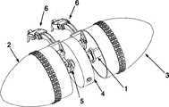
本发明是一种便携二轮二腿组合式可变形机器人,如图1所示,包括机架1、左驱动轮2、右驱动轮3、控制系统4、伸缩机构5和多自由度腿6。The present invention is a portable two-wheel and two-leg combined deformable robot, as shown in Figure 1, comprising a
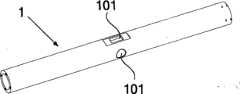
所述的机架1为圆筒结构,如图2所示,机架1两端开有四个螺纹孔用于固连左驱动轮2和右驱动轮3。机架1的中部通过螺钉以及夹紧的方式固定安装有控制系统4和两条多自由度腿6,机架中部还开有走线孔101,便于控制系统4布线;机架1上安装有伸缩机构5。The
所述左驱动轮2和右驱动轮3结构相同,如图3所示,以左驱动轮2为例包括左驱动轮壳201、万向联轴节202、伸缩导向机构203、驱动电机204和减震弹簧205。所述左驱动轮壳201为一体加工而成的圆弧顶部锥形结构,如图4所示,左驱动轮壳201内部空心;左驱动轮壳201内部安装有圆环状悬挂平台206,悬挂平台206上开有通孔A207;且在左驱动轮壳201内部圆弧顶处还设有连接头208,连接头208用来与万向联轴节202连接。左驱动轮壳201外侧周向位置上设有横纵交错的花纹状突起209,确保机器人具有较强的抓地力和爬坡性能。Described
所述伸缩导向机构203包括前端座210、固定座211、后端座212和三根移动导杆213,如图5所示。其中,后端座212为圆环状,三根移动导杆213均为圆柱状,且三根移动导杆213的一端固定在前端座210上,另一端穿过固定座211上与移动导杆213相应的孔,最后与后端座212固定连接,固定座211可在前端座210与后端座212间滑动,使前端座210与后端座212形成移动副。所述前端座210上连接有万向联轴节202,万向联轴节202通过销钉与左驱动轮壳201内部的连接头208固连,确保左驱动轮壳201随前端座210一起做轴向伸缩运动。所述后端座212侧边上设置有多个与左驱动轮壳201内部悬挂平台206上的通孔A207对应的,且带有通孔B214的悬挂架215,通孔A207与通孔B214间通过减震弹簧205相连,由此,左驱动轮壳201与伸缩导向机构203相对固定。所述的三根移动导杆213之间相互平行。The
机架1内部安装驱动电机204,且机架1两端通过螺钉分别与左驱动轮2与右驱动轮3中的电机座216固连,从而使固定座211具有绕机架1轴线的转动自由度。所述驱动电机204为集成有编码器的电机,通过编码器可读取驱动电机204的角度信息和位置信息。驱动电机204通过螺钉连接固定在电机座216上,电机座216与固定座211之间为轴承连接,驱动电机204的电机轴穿过电机座216,插入到固定座211中,且与固定座211固定。驱动电机204工作时,通过电机轴的转动可带动固定座211转动,从而带动伸缩导向机构203转动,由此,伸缩导向机构203将具有沿其轴向的移动自由度和转动自由度。The
所述的伸缩机构5包括驱动丝杆501、左丝杆支座502、右丝杆支座503、伸缩电机504、伸缩电机座505、齿轮A506和齿轮B507,如图6所示;其中驱动丝杆501两端分别连接在左驱动轮2与右驱动轮3中的后端座212上,通过驱动丝杆501与固定在后端座212上的螺母的螺旋运动,使左驱动轮2与右驱动轮3中的后端座212、前端座210与移动导杆213共同水平移动,从而使左驱动轮2和右驱动轮3同步伸展或收合。左丝杆支座502与右丝杆支座503分别与驱动丝杆501活动连接,使左丝杆支座502、右丝杆支座503与驱动丝杆501之间构成转动副,具有转动自由度;通过左丝杆支座502与右丝杆支座503可确保驱动丝杆501只具有沿其自身轴线的转动自由度,而不具有移动自由度;伸缩电机504通过螺钉与伸缩电机座505固连,伸缩电机座505通过螺钉以及夹紧的方式固定套接在机架1上;所述伸缩电机504为集成有编码器的电机,通过编码器可读取伸缩电机504的角度信息和位置信息;齿轮A506与齿轮B507构成一级传动齿轮副,齿轮B507与伸缩电机504输出轴固连,齿轮A506与驱动丝杆501固连,齿轮A506与齿轮B507相互啮合,通过齿轮A506与齿轮B507的啮合传动来调节驱动丝杆501的转动速度,所述齿轮A的直径大于齿轮B的直径。其中,驱动丝杆501左端到左丝杠支座502的距离与驱动丝杆501右端到右丝杠支座503的距离相等,且小于移动导杆213的长度。The
所述的多自由度腿6包含左多自由度腿601和右多自由度腿602,左多自由度腿601和右多自由度腿602结构相同,均包括腿固定架603、第一关节电机604、第一关节机架605、第二关节电机606、第二关节机架607和滚轮608,如图7所示。滚轮608通过螺钉固连在第二关节机架607中部,第二关节机架607与第二关节电机606的电机轴轴接;第二关节电机606固定安装在第一关节机架605上,第一关节机架605与第一关节电机604的电机轴轴接;第一关节电机604固定在腿固定架603上,腿固定架603通过螺钉与机架1固连。多自由度腿6在机器人正常行驶时起到平衡支撑的作用,在机器人越障时提供越障的主要动力矩。多自由度腿6中可安装有n个关节电机与n个关节机架,n为正整数,且n≥2。The multi-degree-of-
所述控制系统4包括控制系统壳体401、无线视觉摄像头402、主控电路403、电源404、传感器A405和传感器B406、编码器读数单元407,如图8所示;其中,控制系统壳体401为内部空心的圆柱形壳体,主控电路403、电源404、传感器A405和传感器B406、编码器读数单元407设置在控制系统壳体401内部。控制系统壳体401中轴线上开有通孔C408,使控制系统壳体401固定套接在机架1上的走线孔101处,控制系统壳体401的圆周面上开有无线视觉摄像头安装孔409,无线视觉摄像头402通过无线视觉摄像头安装孔409镶嵌在控制系统壳体401上,无线视觉摄像4头02主要用于传输机器人行进前方的实时视觉图像信息;编码器读数单元407用来读取驱动电机204和伸缩电机504上编码器发送的驱动电机204和伸缩电机504的转动角度信息,并将此转动角度信息反馈给主控电路403;传感器A405用于监测左驱动轮2与右驱动轮3的收合状态,当左驱动轮2与右驱动轮3完全收合时将提供给主控电路403收合信号;传感器B406用于检测左驱动轮2与右驱动轮3的展开状态,当左驱动轮2与右驱动轮3完全展开时将提供给主控电路403展开信号;主控电路403用于处理传感器A405与传感器B406发送的收合与展开的控制信号,驱动第一关节电机604、第二关节电机606、伸缩电机504及驱动电机204按控制信号的要求运动;电源用于分别给传感器A405、传感器B406、编码器读数单元407、无线视觉摄像头402、主控电路403及第一关节电机604、第二关节电机606、伸缩电机504及驱动电机204提供驱动电源。The
本发明机器人在实施操作时具有展开和收合两种状态;展开状态如图1所示,此时机器人既可以在相对平坦地面灵活运动快速行驶,执行相应的赋予任务,也可以在复杂的崎岖环境中横越草地沙砾、翻越台阶等典型障碍,完成指定工作;收合状态如图10所示,此时机器人留出左驱动轮2与右驱动轮3于外界,多自由度腿6收拢于左驱动轮2与右驱动轮3内部,整个机器人外形似于椭球,极具伪装,不易被察觉。The robot of the present invention has two states of unfolding and collapsing when performing operations; the unfolding state is shown in Figure 1, at this time the robot can move flexibly and quickly on a relatively flat ground to perform corresponding assigned tasks, and can also move on complex rugged terrain. In the environment, cross typical obstacles such as grass, gravel, and steps to complete the designated work; the collapsed state is shown in Figure 10. At this time, the robot leaves the
本发明机器人在实施收合过程时,左多自由度腿601与右多自由度腿602的第一关节电机604运动,驱动第一关节机架605做靠近机架1的旋转运动;随后,第二关节电机606运动,驱动第二关节机架607做靠近机架1的旋转运动,直到收合到设定位置,至此使整个左多自由度腿601与右多自由度腿602蜷缩包络在机架1周侧位置。此时,伸缩机构5驱动左驱动轮2、右驱动轮3同步收合往机架1中部靠近,最终实现左驱动轮2、右驱动轮3全包覆左多自由度腿601、右多自由度腿602及控制系统4。When the robot of the present invention implements the folding process, the first
本发明机器人在实施展开过程时与收合过程为逆向顺序实施,伸缩机构5驱动左驱动轮2与右驱动轮3同步展开远离机架1中部,可在控制系统4中设定的左驱动轮2与右驱动轮3展开的位置,随后,左多自由度腿601、右多自由度腿602依次展开第二关节机架607,再展开第一关节机架605。The robot of the present invention implements the unfolding process and the folding process in a reverse sequence. The
本发明机器人在设计上精益结构减轻重量;通过左驱动轮2与右驱动轮3以及多自由度腿6结合的方式,可使机器人既能在平坦环境中高速行走,又能在崎岖环境中翻越各种障碍继续执行任务;左驱动轮2与右驱动轮3的驱动轮壳采用弹簧悬挂减震设计,能够承受数米的自由落体冲击;左驱动轮2与右驱动轮3的收缩,能够将机器人很好的伪装起来,不易被察觉;较小的尺寸设计既便于随身携带亦可随手抛掷于前方;机器人功能较全,控制简单,既可应用于降低伤亡避免巨大损失,还可以用于恶劣环境下的科学研究与工程应用,具有广泛的应用背景和市场前景。The design of the robot in the present invention has a lean structure to reduce weight; through the combination of the
Claims (10)
Translated fromChinesePriority Applications (1)
| Application Number | Priority Date | Filing Date | Title |
|---|---|---|---|
| CN2010102794248ACN102050167B (en) | 2010-09-10 | 2010-09-10 | Portable two-wheeled two-leg combined transformable robot |
Applications Claiming Priority (1)
| Application Number | Priority Date | Filing Date | Title |
|---|---|---|---|
| CN2010102794248ACN102050167B (en) | 2010-09-10 | 2010-09-10 | Portable two-wheeled two-leg combined transformable robot |
Publications (2)
| Publication Number | Publication Date |
|---|---|
| CN102050167Atrue CN102050167A (en) | 2011-05-11 |
| CN102050167B CN102050167B (en) | 2012-05-16 |
Family
ID=43955074
Family Applications (1)
| Application Number | Title | Priority Date | Filing Date |
|---|---|---|---|
| CN2010102794248AExpired - Fee RelatedCN102050167B (en) | 2010-09-10 | 2010-09-10 | Portable two-wheeled two-leg combined transformable robot |
Country Status (1)
| Country | Link |
|---|---|
| CN (1) | CN102050167B (en) |
Cited By (11)
| Publication number | Priority date | Publication date | Assignee | Title |
|---|---|---|---|---|
| CN102267505A (en)* | 2011-06-29 | 2011-12-07 | 北京航空航天大学 | Portable telescopic spherical throwing detection robot |
| CN102581836A (en)* | 2012-02-29 | 2012-07-18 | 哈尔滨工程大学 | Mobile robot coordinately driven by multifunctional mechanical arms and wheels |
| CN103273981A (en)* | 2013-06-20 | 2013-09-04 | 北京信息科技大学 | Transformable search-and-rescue robot with multiple motion tread |
| CN106476925A (en)* | 2016-11-04 | 2017-03-08 | 哈尔滨工业大学 | Small-sized movable robot with wheel legs |
| CN108818548A (en)* | 2018-06-20 | 2018-11-16 | 乌鲁木齐明华智能电子科技有限公司 | A kind of safety protection robot of complex environment intelligent barrier avoiding |
| CN108922268A (en)* | 2018-08-10 | 2018-11-30 | 浙江师范大学 | A kind of education and instruction robot of convertible |
| CN111469946A (en)* | 2020-04-24 | 2020-07-31 | 上海宇航系统工程研究所 | Bionic mobile robot with crawling and rolling functions |
| CN112455155A (en)* | 2020-11-26 | 2021-03-09 | 腾讯科技(深圳)有限公司 | Multi-modal deformation wheel, control method and device thereof, electronic equipment and storage medium |
| US11247089B2 (en) | 2019-08-22 | 2022-02-15 | Robotic Research Opco, Llc | Chemical and biological warfare agent decontamination drone |
| US11247522B2 (en) | 2016-10-27 | 2022-02-15 | Robotic Research Opco, Llc | Vehicle capable of multiple varieties of locomotion |
| US11340618B2 (en) | 2019-08-08 | 2022-05-24 | Robotic Research Opco, Llc | Drone based inspection system at railroad crossings |
Citations (6)
| Publication number | Priority date | Publication date | Assignee | Title |
|---|---|---|---|---|
| JP2004148439A (en)* | 2002-10-30 | 2004-05-27 | Sony Corp | Spherical robot and spherical robot control method |
| CN1616257A (en)* | 2002-08-22 | 2005-05-18 | 北京邮电大学 | Structurally Improved Spherical Robot Omnidirectional Walking Device |
| CN1669745A (en)* | 2005-04-05 | 2005-09-21 | 西安电子科技大学 | An omnidirectional rolling spherical robotic device with a stable platform |
| CN1817580A (en)* | 2006-03-15 | 2006-08-16 | 北京邮电大学 | Spherical walking robot with telescopic arm |
| CN2846267Y (en)* | 2005-06-17 | 2006-12-13 | 北京航空航天大学 | Ominibearing moving ball shape robot |
| JP2007112168A (en)* | 2005-10-18 | 2007-05-10 | Yaskawa Electric Corp | Spherical moving device |
- 2010
- 2010-09-10CNCN2010102794248Apatent/CN102050167B/ennot_activeExpired - Fee Related
Patent Citations (6)
| Publication number | Priority date | Publication date | Assignee | Title |
|---|---|---|---|---|
| CN1616257A (en)* | 2002-08-22 | 2005-05-18 | 北京邮电大学 | Structurally Improved Spherical Robot Omnidirectional Walking Device |
| JP2004148439A (en)* | 2002-10-30 | 2004-05-27 | Sony Corp | Spherical robot and spherical robot control method |
| CN1669745A (en)* | 2005-04-05 | 2005-09-21 | 西安电子科技大学 | An omnidirectional rolling spherical robotic device with a stable platform |
| CN2846267Y (en)* | 2005-06-17 | 2006-12-13 | 北京航空航天大学 | Ominibearing moving ball shape robot |
| JP2007112168A (en)* | 2005-10-18 | 2007-05-10 | Yaskawa Electric Corp | Spherical moving device |
| CN1817580A (en)* | 2006-03-15 | 2006-08-16 | 北京邮电大学 | Spherical walking robot with telescopic arm |
Cited By (13)
| Publication number | Priority date | Publication date | Assignee | Title |
|---|---|---|---|---|
| CN102267505A (en)* | 2011-06-29 | 2011-12-07 | 北京航空航天大学 | Portable telescopic spherical throwing detection robot |
| CN102581836A (en)* | 2012-02-29 | 2012-07-18 | 哈尔滨工程大学 | Mobile robot coordinately driven by multifunctional mechanical arms and wheels |
| CN103273981A (en)* | 2013-06-20 | 2013-09-04 | 北京信息科技大学 | Transformable search-and-rescue robot with multiple motion tread |
| US11247522B2 (en) | 2016-10-27 | 2022-02-15 | Robotic Research Opco, Llc | Vehicle capable of multiple varieties of locomotion |
| CN106476925A (en)* | 2016-11-04 | 2017-03-08 | 哈尔滨工业大学 | Small-sized movable robot with wheel legs |
| CN108818548A (en)* | 2018-06-20 | 2018-11-16 | 乌鲁木齐明华智能电子科技有限公司 | A kind of safety protection robot of complex environment intelligent barrier avoiding |
| CN108818548B (en)* | 2018-06-20 | 2021-07-20 | 乌鲁木齐明华智能电子科技有限公司 | A security robot for intelligent obstacle avoidance in complex environments |
| CN108922268A (en)* | 2018-08-10 | 2018-11-30 | 浙江师范大学 | A kind of education and instruction robot of convertible |
| CN108922268B (en)* | 2018-08-10 | 2024-05-03 | 北京育悦科技有限公司 | Changeable education teaching robot |
| US11340618B2 (en) | 2019-08-08 | 2022-05-24 | Robotic Research Opco, Llc | Drone based inspection system at railroad crossings |
| US11247089B2 (en) | 2019-08-22 | 2022-02-15 | Robotic Research Opco, Llc | Chemical and biological warfare agent decontamination drone |
| CN111469946A (en)* | 2020-04-24 | 2020-07-31 | 上海宇航系统工程研究所 | Bionic mobile robot with crawling and rolling functions |
| CN112455155A (en)* | 2020-11-26 | 2021-03-09 | 腾讯科技(深圳)有限公司 | Multi-modal deformation wheel, control method and device thereof, electronic equipment and storage medium |
Also Published As
| Publication number | Publication date |
|---|---|
| CN102050167B (en) | 2012-05-16 |
Similar Documents
| Publication | Publication Date | Title |
|---|---|---|
| CN102050167A (en) | Portable two-wheeled two-leg combined transformable robot | |
| CN100553896C (en) | EOD robot | |
| CN103287523B (en) | The composite deformation mobile robot that a kind of elastic foot is combined with wheel type motion mechanism | |
| US8306664B1 (en) | Self-balancing robot having a shaft-mounted head | |
| CN103538644B (en) | A kind of robot with rolling movement and sufficient formula walking function | |
| CN102179812B (en) | Ball-shaped robot used for detection | |
| CN107804114A (en) | A multi-wheeled all-terrain robot with variable wheel diameter and special-shaped wheels | |
| CN103274064B (en) | A kind of collapsible six-freedom parallel posture adjustment platform | |
| CN203237312U (en) | Combination shape-shifting mobile robot with elastic feet and wheel-type movement mechanism combined | |
| CN103264382B (en) | Wheel-arm-hybrid obstacle surmounting robot with radial telescopic wheels | |
| CN105172933A (en) | Spider-imitating multi-foot robot platform | |
| CN113212579A (en) | Ball wheel leg composite mobile robot capable of being operated outwards | |
| CN102267505A (en) | Portable telescopic spherical throwing detection robot | |
| CN103112515A (en) | Wheel leg combined type robot | |
| CN102211624A (en) | Searching and rescuing positioning system robot | |
| CN113894822B (en) | Eight-legged robot with bionic rigid-flexible coupled legs and control method | |
| CN107175643A (en) | A kind of Post disaster relief robot and its control system and method based on machine vision | |
| CN102773860A (en) | Throwable variable structure spherical robot | |
| CN210793393U (en) | Six sufficient C type leg track compound robot | |
| CN109533051B (en) | Convertible stair climbing robot with collapsible swing arm | |
| CN106741263A (en) | Four-track adaptive road condition adjustable center of gravity mechanism | |
| WO2011102528A1 (en) | Mobile robot | |
| KR20140111162A (en) | Multi joint robot to drive rough terrain | |
| CN207208244U (en) | It is a kind of can actively adjust landing before posture hopping robot | |
| CN105346614B (en) | A kind of climbing robot of flexible support driving mechanism |
Legal Events
| Date | Code | Title | Description |
|---|---|---|---|
| C06 | Publication | ||
| PB01 | Publication | ||
| C10 | Entry into substantive examination | ||
| SE01 | Entry into force of request for substantive examination | ||
| C14 | Grant of patent or utility model | ||
| GR01 | Patent grant | ||
| C17 | Cessation of patent right | ||
| CF01 | Termination of patent right due to non-payment of annual fee | Granted publication date:20120516 Termination date:20120910 |