CN102049784A - Industrial robot - Google Patents
Industrial robotDownload PDFInfo
- Publication number
- CN102049784A CN102049784ACN2009103090850ACN200910309085ACN102049784ACN 102049784 ACN102049784 ACN 102049784ACN 2009103090850 ACN2009103090850 ACN 2009103090850ACN 200910309085 ACN200910309085 ACN 200910309085ACN 102049784 ACN102049784 ACN 102049784A
- Authority
- CN
- China
- Prior art keywords
- wrist unit
- axis
- bevel gear
- industrial robot
- transmission shaft
- Prior art date
- Legal status (The legal status is an assumption and is not a legal conclusion. Google has not performed a legal analysis and makes no representation as to the accuracy of the status listed.)
- Pending
Links
Images


Classifications
- B—PERFORMING OPERATIONS; TRANSPORTING
- B25—HAND TOOLS; PORTABLE POWER-DRIVEN TOOLS; MANIPULATORS
- B25J—MANIPULATORS; CHAMBERS PROVIDED WITH MANIPULATION DEVICES
- B25J17/00—Joints
- B25J17/02—Wrist joints
- B25J17/0283—Three-dimensional joints
- B25J17/0291—Three-dimensional joints having axes crossing at an oblique angle, i.e. other than 90 degrees
- Y—GENERAL TAGGING OF NEW TECHNOLOGICAL DEVELOPMENTS; GENERAL TAGGING OF CROSS-SECTIONAL TECHNOLOGIES SPANNING OVER SEVERAL SECTIONS OF THE IPC; TECHNICAL SUBJECTS COVERED BY FORMER USPC CROSS-REFERENCE ART COLLECTIONS [XRACs] AND DIGESTS
- Y10—TECHNICAL SUBJECTS COVERED BY FORMER USPC
- Y10T—TECHNICAL SUBJECTS COVERED BY FORMER US CLASSIFICATION
- Y10T74/00—Machine element or mechanism
- Y10T74/20—Control lever and linkage systems
- Y10T74/20207—Multiple controlling elements for single controlled element
- Y10T74/20305—Robotic arm
- Y10T74/20317—Robotic arm including electric motor
- Y—GENERAL TAGGING OF NEW TECHNOLOGICAL DEVELOPMENTS; GENERAL TAGGING OF CROSS-SECTIONAL TECHNOLOGIES SPANNING OVER SEVERAL SECTIONS OF THE IPC; TECHNICAL SUBJECTS COVERED BY FORMER USPC CROSS-REFERENCE ART COLLECTIONS [XRACs] AND DIGESTS
- Y10—TECHNICAL SUBJECTS COVERED BY FORMER USPC
- Y10T—TECHNICAL SUBJECTS COVERED BY FORMER US CLASSIFICATION
- Y10T74/00—Machine element or mechanism
- Y10T74/20—Control lever and linkage systems
- Y10T74/20207—Multiple controlling elements for single controlled element
- Y10T74/20305—Robotic arm
- Y10T74/20329—Joint between elements
Landscapes
- Engineering & Computer Science (AREA)
- Robotics (AREA)
- Mechanical Engineering (AREA)
- Manipulator (AREA)
Abstract
Description
Translated fromChinese技术领域technical field
本发明涉及一种机器人,尤其涉及一种具有依次连接的多个手腕单元的工业机器人。The invention relates to a robot, in particular to an industrial robot with a plurality of wrist units connected in sequence.
背景技术Background technique
工业机器人通常具备:可绕第一轴线转动地设置的第一手腕单元,该第一手腕单元的前端一侧形成一个叉形结构;可转动地设置在该叉形结构的两侧部之间的第二手腕单元;以及在该第二手腕单元的前端一侧,可转动地设置的第三手腕单元。第三手腕单元作为工业机器人的末端轴,如六轴工业机器人的第六轴,可用于装设夹具、切削工具及探测器等末端执行器以执行各种任务。上述第一及第三手腕单元的旋转轴线通常分别与第二手腕单元的旋转轴线正交,因此,第三手腕单元及末端执行器在跟随第二手腕单元转动的过程中易碰触第一手腕单元,使第二手腕单元的旋转角度受到限制,不能绕其旋转轴线全方位转动。Industrial robots usually have: a first wrist unit that is rotatably arranged around a first axis, and a fork-shaped structure is formed on one side of the front end of the first wrist unit; a second wrist unit; and a third wrist unit rotatably provided on the front end side of the second wrist unit. The third wrist unit is used as the end axis of the industrial robot, such as the sixth axis of the six-axis industrial robot, which can be used to install end effectors such as fixtures, cutting tools, and detectors to perform various tasks. The rotation axes of the above-mentioned first and third wrist units are usually perpendicular to the rotation axes of the second wrist unit respectively, therefore, the third wrist unit and the end effector are likely to touch the first wrist unit during the rotation of the second wrist unit. unit, so that the rotation angle of the second wrist unit is restricted and cannot rotate in all directions around its rotation axis.
另外,第一手腕单元的叉形结构处设有第一电机以及第一减速组件,第一减速组件用于减速第一电机转速且驱动第二手腕单元;第二手腕单元的前端一侧设有第二电机以及第二减速组件,第二减速组件用于减速第二电机转速且驱动第三手腕单元。上述结构增加了手腕单元的体积及占用的空间,不利于工业机器人在较狭小操作空间中的应用。并且,第二手腕单元及第三手腕单元重量较重,从而惯性矩变大,给提高控制的准确性及快速性造成困难。In addition, the fork-shaped structure of the first wrist unit is provided with a first motor and a first deceleration assembly, the first deceleration assembly is used to decelerate the speed of the first motor and drive the second wrist unit; the front end of the second wrist unit is provided with The second motor and the second deceleration assembly, the second deceleration assembly is used to decelerate the rotation speed of the second motor and drive the third wrist unit. The above-mentioned structure increases the volume and occupied space of the wrist unit, which is not conducive to the application of industrial robots in relatively narrow operating spaces. Moreover, the weight of the second wrist unit and the third wrist unit is relatively heavy, so the moment of inertia becomes large, which makes it difficult to improve the accuracy and speed of control.
发明内容Contents of the invention
鉴于上述内容,有必要提供一种结构紧凑、占用空间较小的工业机器人,该工业机器人的与位于其末端的手腕单元相连的手腕单元可作全方位转动。In view of the above, it is necessary to provide an industrial robot with a compact structure and a small footprint, the wrist unit connected to the wrist unit at the end of the industrial robot can rotate in all directions.
一种工业机器人,包括可绕第一轴线转动的第一手腕单元、可绕第二轴线转动且被第一手腕单元支撑的第二手腕单元、可绕第三轴线转动且被第二手腕单元支撑的第三手腕单元、驱动该第二手腕单元的第一电机及第一传动链、驱动该第三手腕单元的第二电机及第二传动链以及控制该第一电机及第二电机分别动作的控制装置。第三手腕单元为该工业机器人的最终轴,该第一轴线、第二轴线及第三轴线相交于一交点。该第二轴线与第三轴线的夹角大于0度小于90度;该第一传动链包括第一锥齿轮组,该第一锥齿轮组的其中一个锥齿轮相对于该第二手腕单元固定;该第二传动链包括与该第二手腕单元转动连接的中间轴及沿中间轴的旋转轴线间隔设置的第二锥齿轮组及第三锥齿轮组,该第三锥齿轮组的其中一个锥齿轮相对于该第三手腕单元固定,并且该中间轴的旋转轴线通过该交点且与第二轴线正交。An industrial robot, comprising a first wrist unit rotatable around a first axis, a second wrist unit rotatable around a second axis and supported by the first wrist unit, rotatable around a third axis and supported by the second wrist unit The third wrist unit, the first motor and the first transmission chain that drive the second wrist unit, the second motor and the second transmission chain that drive the third wrist unit, and the controls that control the actions of the first motor and the second motor respectively control device. The third wrist unit is the final axis of the industrial robot, and the first axis, the second axis and the third axis intersect at an intersection. The included angle between the second axis and the third axis is greater than 0 degrees and less than 90 degrees; the first transmission chain includes a first bevel gear set, and one of the bevel gears of the first bevel gear set is fixed relative to the second wrist unit; The second transmission chain includes an intermediate shaft rotatably connected to the second wrist unit and a second bevel gear set and a third bevel gear set arranged at intervals along the axis of rotation of the intermediate shaft, one of the bevel gears of the third bevel gear set Fixed relative to the third wrist unit, and the axis of rotation of the intermediate shaft passes through the intersection point and is orthogonal to the second axis.
由于第二轴线与第三轴线的夹角大于0度小于90度,即第二轴线与第三轴线斜交,第三手腕单元在跟随第二手腕单元转动时可避免与第一手腕单元相交,从而第二手腕单元绕第二轴线的转动角度可不受限制、作全方位的转动。另外,通过配置第一至第三锥齿轮组及中间轴,可将第一电机及第二电机的动力传递至第二手腕单元及第三手腕单元,并可减小第二手腕单元及第三手腕单元沿各自旋转轴向的尺寸,使工业机器人结构紧凑,占用空间减小,可实现手腕单元的小型化,使工业机器人可在更狭窄的作业空间内与周围物体无干涉地进行作业。Since the angle between the second axis and the third axis is greater than 0 degrees and less than 90 degrees, that is, the second axis is oblique to the third axis, the third wrist unit can avoid intersecting with the first wrist unit when rotating with the second wrist unit, Therefore, the rotation angle of the second wrist unit around the second axis can be rotated in all directions without restriction. In addition, by configuring the first to third bevel gear sets and the intermediate shaft, the power of the first motor and the second motor can be transmitted to the second wrist unit and the third wrist unit, and the size of the second wrist unit and the third wrist unit can be reduced. The size of the wrist unit along the respective axis of rotation makes the industrial robot compact and takes up less space, which can realize the miniaturization of the wrist unit, so that the industrial robot can work in a narrower working space without interference with surrounding objects.
附图说明Description of drawings
图1是简略表示本发明实施例的工业机器人的侧视图。Fig. 1 is a side view schematically showing an industrial robot according to an embodiment of the present invention.
图2是图1所示的机器人的手腕结构的立体组装图,图中省略了电机及设于电机输出端的齿轮组。FIG. 2 is a three-dimensional assembled view of the wrist structure of the robot shown in FIG. 1 , in which the motor and the gear set at the output end of the motor are omitted.
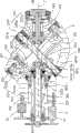
图3是图2所示手腕结构沿III III方向的剖面示意图。Fig. 3 is a schematic cross-sectional view of the wrist structure shown in Fig. 2 along the direction III III.
具体实施方式Detailed ways
下面结合附图及实施例对本发明的工业机器人作进一步的详细说明,并以六轴工业机器人为例进行说明。The industrial robot of the present invention will be further described in detail below with reference to the accompanying drawings and embodiments, and a six-axis industrial robot is taken as an example for illustration.
图1所示为本发明实施方式的工业机器人100的简略示意图。机器人100为六轴工业机器人,其包括基座11、可转动地设置于基座11的机架12、可转动地设置于机架12一端的大臂13、与大臂13可转动连接的连接手腕14、依次可转动连接的第一至第三手腕单元15、16、18以及控制装置19。其中,第一手腕单元15与连接手腕14可转动连接,第三手腕单元18作为工业机器人100的末端轴,可用于装设夹具、刀具或者探测仪器等末端执行器。控制装置19用于产生控制指令,以控制各驱动装置,如电机等动作,使工业机器人100得到预设的位置及姿势。FIG. 1 is a schematic diagram of an
第一至第三手腕单元15、16、18可分别绕第一至第三轴线A、B、C旋转。第一至第三轴线A、B、C相交于一个交点D,且第二轴线B与第三轴线C斜交,换言之,第二轴线B与第三轴线C的夹角θ大于0度小于90度。第二轴线B可与第一轴线A正交,也可与第一轴线A斜交,换言之,第二轴线B与第一轴线A之间的夹角β可为90度,也可大于0度小于90度。具体在本实施方式中,夹角θ、β均为45度。机架12、大臂13及连接手腕14也可分别绕轴线121、131、141旋转。The first to
因第二轴线B与第三轴线C斜交,当第二手腕单元16带动第三手腕单元18旋转时,第三手腕单元18及与之连接的末端执行器可以避开与第一手腕单元15相触碰的位置,从而第二手腕单元16绕第二轴线B的转动范围不受限制,可作360度全方位转动。Because the second axis B is oblique to the third axis C, when the
图2及图3示出了第一至第三手腕单元15、16、18的详细结构。第二手腕单元16由第一电机21及第一传动链(图未标)驱动,第三手腕单元18由第二电机31及第二传动链(图未标)驱动。第一电机21及第二电机31均设于第一手腕15上。2 and 3 show detailed structures of the first to
第一手腕单元15包括一体形成的第一连接部151及第二连接部152。第一连接部151大致呈半球形壳体,第二连接部152形成于第一连接部151上,并大致为沿第一轴线A方向延伸的圆柱体。第二连接部152中部沿第一轴线A方向贯通形成一个中空部153。The
第二手腕单元16大致为一圆形盖体,并贯通设有多个连接孔161及一个沿第二轴线B方向延伸的安装孔162。安装孔162用于安装第三手腕单元18。The
第二手腕单元16可转动地设置于第一连接部151的前端一侧,并被第一手腕单元15悬臂支撑。第三手腕单元18可转动地穿设于第二手腕单元16的安装孔162,并被第二手腕单元16悬臂支撑。第二手腕单元16与第一手腕单元15之间形成一个与中空部153相连通的容置部160。容置部160内可收容第一传动链及第二传动链的部分结构。第一手腕单元15设有第一交叉磙子轴承155,用于支撑第二手腕单元16。第二手腕单元16设有第二交叉磙子轴承163,用于支撑第三手腕单元18。因交叉磙子轴承的内轮与外轮间,间隔交叉的磙子彼此成直角方式排列,具有可同时承受来自多方向的载荷且变形较小的优点,可确保配合的紧密性以及转动的刚性。The
第一传动链包括第一传动轴221,设于第一传动轴221一端的第一锥齿轮组223。第一电机21设于第一传动轴221的另一端,以驱动第一传动轴221。第一传动轴221由轴承2211可转动地支撑于第一手腕单元15的中空部153内。具体在本实施例中,第一传动轴221沿轴向开设一贯穿孔2212。第一锥齿轮组223为单级齿轮,其中一个锥齿轮223a相对于第二手腕单元16固定设置,可通过将多个螺纹件156分别穿设于第二手腕单元16的连接孔161将锥齿轮223a与第二手腕单元16锁固。另一个锥齿轮223b相对于第一传动轴221固定设置,其连接方式可为键连接或过盈连接等。锥齿轮223a中部设有沿轴向贯通的中心孔2232。The first transmission chain includes a
第二传动链包括依次设置的第二传动轴321、第二锥齿轮组323、中间轴324以及第三锥齿轮组325。The second transmission chain includes a
第二传动轴321穿设于第一传动轴221的贯穿孔2212,且其两端分别伸出贯穿孔2212外,并由设于第一传动轴221内壁与第二传动轴321之间的轴承3211可转动支撑。且第二传动轴321及第一传动轴221的旋转轴线与第一轴线A重合。The
第二电机31及第二锥齿轮组323分别设置于第二传动轴321的两端,且在第一轴线A方向上,第一电机21及第二电机31相互偏置,且分别设置于第一手腕单元15沿轴向的相对两侧。第一电机21及第二电机31的输出轴可分别通过齿轮组(图未标)与第一传动轴221及第二传动轴321连接。The
中间轴324穿设锥齿轮223a的中心孔2232,且两端分别通过轴承3241、3242与第二手腕单元16可转动连接。中间轴324的旋转轴线E通过交点D且与第二轴线B正交,以使第三手腕单元18在跟随第二手腕单元16转动时,第二电机31仍可通过第二传动链将动力传送至第三手腕单元18。The
第二锥齿轮组323及第三锥齿轮组325沿中间轴324的轴向间隔设置,且分别邻近中间轴324的两端。第一锥齿轮组323及第二锥齿轮组325均为单级齿轮。其中,第一锥齿轮组323的其中一个锥齿轮323a与第二传动轴321固定连接,另一锥齿轮323b与中间轴324固定连接。锥齿轮323a与锥齿轮223b在沿第二轴线B方向上相互偏置,从而锥齿轮323a及锥齿轮223a在垂直于第一轴线A的平面上的投影可部分重合,从而减小整体结构沿径向的尺寸。第二锥齿轮组325的其中一个锥齿轮325a相对于第三手腕单元18固定设置以带动第三手腕单元18绕第三轴线C旋转,另一锥齿轮325b与中间轴324固定连接。The second bevel gear set 323 and the third bevel gear set 325 are arranged at intervals along the axial direction of the
上述工业机器人100的第一电机21及第二电机31设置于第一手腕单元15的一端,并通过第一传动链及第二传动链将动力分别传递至第二手腕单元16及第三手腕单元18,第二手腕单元16及第三手腕单元18仅需分别与锥齿轮223a及锥齿轮323a直接连接,使得第二手腕单元16及第三手腕单元18沿各自轴向的尺寸均较小,可实现手腕单元的小型化,有利于工业机器人100在较狭窄的作业空间内与周围物体无干涉地进行作业。同时,还减轻了第二手腕单元16的惯性矩,有利于对第二手腕单元16及第三手腕单元18进行准确、快速地控制。此外,上述第一至第三锥齿轮组223、323、325均采用单级齿轮,并可采用传统的锥齿轮结构,可降低制造成本。The
以下主要介绍工业机器人100第二、第三手腕单元16、18的动作情况,工业机器人100的其余机构,例如机架12、大臂13、第一手腕单元15的动作情况与现有机器人相似。The following mainly introduces the actions of the second and
控制装置19中预设有控制指令,并包括一个补偿单元(图未示)。当控制装置19发出控制指令驱动第一电机21转动时,第一电机21的动力通过第一传动链传递至第二手腕单元16,使第二手腕单元16绕第二轴线B旋转。与此同时,第三手腕单元18将跟随第二手腕单元16绕第二轴线B旋转,第二锥齿轮组323及第三锥齿轮组325的两个齿轮相互啮合,导致第三手腕单元18绕第三轴线C转动一定角度,在此称该转动的角度为跟随转动。为防止第三手腕单元18因跟随第二手腕单元16的转动而失去定位的基准,控制装置19在控制第二手腕单元16旋转的同时发出控制指令控制第二电机31转动,以驱动第二传动链32带动第三手腕单元18绕轴线C旋转相应角度以抵消上述跟随转动,使第二手腕单元16旋转时,第三手腕单元18绕线C仍保持在当前位置。当需要单独调整第三手腕单元18的绕轴线C的旋转角度时,控制装置19再次发出控制指令使第三手腕单元18转动至预设的角度,第三手腕单元18的运动不会影响第二手腕单元16的动作。Control instructions are preset in the
可以理解,工业机器人100的第一传动链及第二传动链还可以进一步增加传动齿轮的级数以获得需要的减速比。另外,也可将第二传动轴321设为空心结构,而将第一传动轴221可转动地穿设于第二传动轴321。It can be understood that the first transmission chain and the second transmission chain of the
可以理解,本发明的机器人100不限于为六轴机器人,其也可为具有较少轴数的机器人,如四轴或者五轴机器人等。It can be understood that the
另外,本领域技术人员还可在本发明精神内做其它变化,当然,这些依据本发明精神所做的变化,都应包含在本发明所要求保护的范围内。In addition, those skilled in the art can also make other changes within the spirit of the present invention. Of course, these changes made according to the spirit of the present invention should be included in the scope of protection claimed by the present invention.
Claims (10)
Priority Applications (2)
| Application Number | Priority Date | Filing Date | Title |
|---|---|---|---|
| CN2009103090850ACN102049784A (en) | 2009-10-30 | 2009-10-30 | Industrial robot |
| US12/703,125US20110106302A1 (en) | 2009-10-30 | 2010-02-09 | Robot arm assembly and industrial robot using the same |
Applications Claiming Priority (1)
| Application Number | Priority Date | Filing Date | Title |
|---|---|---|---|
| CN2009103090850ACN102049784A (en) | 2009-10-30 | 2009-10-30 | Industrial robot |
Publications (1)
| Publication Number | Publication Date |
|---|---|
| CN102049784Atrue CN102049784A (en) | 2011-05-11 |
Family
ID=43926254
Family Applications (1)
| Application Number | Title | Priority Date | Filing Date |
|---|---|---|---|
| CN2009103090850APendingCN102049784A (en) | 2009-10-30 | 2009-10-30 | Industrial robot |
Country Status (2)
| Country | Link |
|---|---|
| US (1) | US20110106302A1 (en) |
| CN (1) | CN102049784A (en) |
Cited By (3)
| Publication number | Priority date | Publication date | Assignee | Title |
|---|---|---|---|---|
| CN105617668A (en)* | 2014-10-30 | 2016-06-01 | 深圳宝葫芦机器人有限公司 | Waist joint device |
| CN107225595A (en)* | 2016-03-23 | 2017-10-03 | 发那科株式会社 | The wrist structure of robot |
| CN108004748A (en)* | 2018-01-19 | 2018-05-08 | 广东美的环境电器制造有限公司 | The detent mechanism and Garment Steamer Machine of ironing board |
Families Citing this family (7)
| Publication number | Priority date | Publication date | Assignee | Title |
|---|---|---|---|---|
| FR2929875B1 (en)* | 2008-04-09 | 2012-01-13 | Aldebaran Robotics | MOTORIZED JOINT HAVING TWO PIVOT LINKS AND HUMANOID ROBOTS IMPLEMENTING THE ARTICULATION |
| CN102029608A (en)* | 2009-09-24 | 2011-04-27 | 鸿富锦精密工业(深圳)有限公司 | Robot |
| DE102012208098A1 (en)* | 2012-05-15 | 2013-11-21 | Kuka Roboter Gmbh | Robotic arm with an adjustment device |
| GB2531994B (en)* | 2014-10-15 | 2020-06-24 | Cmr Surgical Ltd | Surgical articulation |
| CN107538515A (en)* | 2016-12-30 | 2018-01-05 | 天津晨富科技有限公司 | A kind of cradle head of industrial robot |
| CN106737622B (en)* | 2016-12-30 | 2023-12-26 | 北京星和众工设备技术股份有限公司 | Sand blasting robot |
| CN107729637A (en)* | 2017-10-09 | 2018-02-23 | 燕山大学 | Redundant degree of freedom manipulator motion planning and evaluation method based on arm shape angle range |
Family Cites Families (3)
| Publication number | Priority date | Publication date | Assignee | Title |
|---|---|---|---|---|
| US4068536A (en)* | 1976-12-23 | 1978-01-17 | Cincinnati Milacron Inc. | Manipulator |
| US4703668A (en)* | 1985-09-25 | 1987-11-03 | Champion Spark Plug Company | Wrist mechanism for a robot arm |
| US4787270A (en)* | 1987-02-11 | 1988-11-29 | Cincinnati Milacron Inc. | Robotic manipulator |
- 2009
- 2009-10-30CNCN2009103090850Apatent/CN102049784A/enactivePending
- 2010
- 2010-02-09USUS12/703,125patent/US20110106302A1/ennot_activeAbandoned
Cited By (7)
| Publication number | Priority date | Publication date | Assignee | Title |
|---|---|---|---|---|
| CN105617668A (en)* | 2014-10-30 | 2016-06-01 | 深圳宝葫芦机器人有限公司 | Waist joint device |
| CN105617668B (en)* | 2014-10-30 | 2018-01-02 | 深圳宝葫芦机器人有限公司 | Waist joint arrangement |
| CN107225595A (en)* | 2016-03-23 | 2017-10-03 | 发那科株式会社 | The wrist structure of robot |
| US10335944B2 (en) | 2016-03-23 | 2019-07-02 | Fanuc Corporation | Robot wrist structure |
| CN107225595B (en)* | 2016-03-23 | 2020-03-03 | 发那科株式会社 | Wrist structure of robot |
| CN108004748A (en)* | 2018-01-19 | 2018-05-08 | 广东美的环境电器制造有限公司 | The detent mechanism and Garment Steamer Machine of ironing board |
| CN108004748B (en)* | 2018-01-19 | 2023-10-27 | 广东美的环境电器制造有限公司 | Positioning mechanism of ironing board and garment steamer |
Also Published As
| Publication number | Publication date |
|---|---|
| US20110106302A1 (en) | 2011-05-05 |
Similar Documents
| Publication | Publication Date | Title |
|---|---|---|
| CN102049784A (en) | Industrial robot | |
| US20110067514A1 (en) | Robot arm assembly and industrial robot using the same | |
| US8429996B2 (en) | Robot arm assembly | |
| US8516920B2 (en) | Robot arm assembly | |
| JP4659098B2 (en) | Parallel link robot with posture change mechanism with 3 degrees of freedom | |
| US7597025B2 (en) | Articulated robot | |
| JP4148280B2 (en) | Parallel link mechanism and industrial robot | |
| JP4232795B2 (en) | Parallel link mechanism and industrial robot | |
| CN101680512B (en) | Gear units and industrial machinery with electric motors | |
| JP2006167863A (en) | Link drive mechanism and industrial robot using the same | |
| JP2007085530A (en) | Hollow reducer | |
| JP2010149214A (en) | Horizontal multi-articulated robot | |
| JPWO2010101203A1 (en) | Robot joint unit and robot | |
| CN102114630A (en) | Robot arm component | |
| JP6729855B2 (en) | Multi-directional driving device, robot joint mechanism, and multi-directional driving method | |
| WO2013018229A1 (en) | Composite drive device and robot | |
| CN103264399B (en) | Robot waist arm Integral synchronous Shuan Qu mechanism and control method thereof | |
| EP3539727B1 (en) | Working device and double-arm type working device | |
| JP5394358B2 (en) | Parallel link robot with posture change mechanism with 3 degrees of freedom | |
| CN101590650B (en) | Decoupled Three Rotational Degrees of Freedom Parallel Mechanism | |
| JP6277672B2 (en) | robot | |
| KR101947697B1 (en) | Parallel actuator with 4-dof | |
| JP2005127475A (en) | Link operating device | |
| JPWO2008136405A1 (en) | Rotation drive device, robot joint structure and robot arm | |
| TWI441721B (en) | Industrial robot |
Legal Events
| Date | Code | Title | Description |
|---|---|---|---|
| C06 | Publication | ||
| PB01 | Publication | ||
| C10 | Entry into substantive examination | ||
| SE01 | Entry into force of request for substantive examination | ||
| C02 | Deemed withdrawal of patent application after publication (patent law 2001) | ||
| WD01 | Invention patent application deemed withdrawn after publication | Application publication date:20110511 |