CN102046840B - Processing apparatus and processing method - Google Patents
Processing apparatus and processing methodDownload PDFInfo
- Publication number
- CN102046840B CN102046840BCN2009801190528ACN200980119052ACN102046840BCN 102046840 BCN102046840 BCN 102046840BCN 2009801190528 ACN2009801190528 ACN 2009801190528ACN 200980119052 ACN200980119052 ACN 200980119052ACN 102046840 BCN102046840 BCN 102046840B
- Authority
- CN
- China
- Prior art keywords
- processing
- workpieces
- workpiece
- supply
- chamber
- Prior art date
- Legal status (The legal status is an assumption and is not a legal conclusion. Google has not performed a legal analysis and makes no representation as to the accuracy of the status listed.)
- Expired - Fee Related
Links
Images


Classifications
- B—PERFORMING OPERATIONS; TRANSPORTING
- B65—CONVEYING; PACKING; STORING; HANDLING THIN OR FILAMENTARY MATERIAL
- B65G—TRANSPORT OR STORAGE DEVICES, e.g. CONVEYORS FOR LOADING OR TIPPING, SHOP CONVEYOR SYSTEMS OR PNEUMATIC TUBE CONVEYORS
- B65G49/00—Conveying systems characterised by their application for specified purposes not otherwise provided for
- B65G49/05—Conveying systems characterised by their application for specified purposes not otherwise provided for for fragile or damageable materials or articles
- B65G49/06—Conveying systems characterised by their application for specified purposes not otherwise provided for for fragile or damageable materials or articles for fragile sheets, e.g. glass
- B65G49/063—Transporting devices for sheet glass
- B65G49/064—Transporting devices for sheet glass in a horizontal position
- B—PERFORMING OPERATIONS; TRANSPORTING
- B65—CONVEYING; PACKING; STORING; HANDLING THIN OR FILAMENTARY MATERIAL
- B65G—TRANSPORT OR STORAGE DEVICES, e.g. CONVEYORS FOR LOADING OR TIPPING, SHOP CONVEYOR SYSTEMS OR PNEUMATIC TUBE CONVEYORS
- B65G49/00—Conveying systems characterised by their application for specified purposes not otherwise provided for
- B65G49/05—Conveying systems characterised by their application for specified purposes not otherwise provided for for fragile or damageable materials or articles
- B65G49/06—Conveying systems characterised by their application for specified purposes not otherwise provided for for fragile or damageable materials or articles for fragile sheets, e.g. glass
- B65G49/067—Sheet handling, means, e.g. manipulators, devices for turning or tilting sheet glass
- H—ELECTRICITY
- H01—ELECTRIC ELEMENTS
- H01L—SEMICONDUCTOR DEVICES NOT COVERED BY CLASS H10
- H01L21/00—Processes or apparatus adapted for the manufacture or treatment of semiconductor or solid state devices or of parts thereof
- H01L21/67—Apparatus specially adapted for handling semiconductor or electric solid state devices during manufacture or treatment thereof; Apparatus specially adapted for handling wafers during manufacture or treatment of semiconductor or electric solid state devices or components ; Apparatus not specifically provided for elsewhere
- H01L21/67005—Apparatus not specifically provided for elsewhere
- H01L21/67011—Apparatus for manufacture or treatment
- H01L21/67155—Apparatus for manufacturing or treating in a plurality of work-stations
- H01L21/67161—Apparatus for manufacturing or treating in a plurality of work-stations characterized by the layout of the process chambers
- H01L21/67173—Apparatus for manufacturing or treating in a plurality of work-stations characterized by the layout of the process chambers in-line arrangement
- H—ELECTRICITY
- H01—ELECTRIC ELEMENTS
- H01L—SEMICONDUCTOR DEVICES NOT COVERED BY CLASS H10
- H01L21/00—Processes or apparatus adapted for the manufacture or treatment of semiconductor or solid state devices or of parts thereof
- H01L21/67—Apparatus specially adapted for handling semiconductor or electric solid state devices during manufacture or treatment thereof; Apparatus specially adapted for handling wafers during manufacture or treatment of semiconductor or electric solid state devices or components ; Apparatus not specifically provided for elsewhere
- H01L21/67005—Apparatus not specifically provided for elsewhere
- H01L21/67011—Apparatus for manufacture or treatment
- H01L21/67155—Apparatus for manufacturing or treating in a plurality of work-stations
- H01L21/67201—Apparatus for manufacturing or treating in a plurality of work-stations characterized by the construction of the load-lock chamber
- H—ELECTRICITY
- H01—ELECTRIC ELEMENTS
- H01L—SEMICONDUCTOR DEVICES NOT COVERED BY CLASS H10
- H01L21/00—Processes or apparatus adapted for the manufacture or treatment of semiconductor or solid state devices or of parts thereof
- H01L21/67—Apparatus specially adapted for handling semiconductor or electric solid state devices during manufacture or treatment thereof; Apparatus specially adapted for handling wafers during manufacture or treatment of semiconductor or electric solid state devices or components ; Apparatus not specifically provided for elsewhere
- H01L21/677—Apparatus specially adapted for handling semiconductor or electric solid state devices during manufacture or treatment thereof; Apparatus specially adapted for handling wafers during manufacture or treatment of semiconductor or electric solid state devices or components ; Apparatus not specifically provided for elsewhere for conveying, e.g. between different workstations
- H01L21/67739—Apparatus specially adapted for handling semiconductor or electric solid state devices during manufacture or treatment thereof; Apparatus specially adapted for handling wafers during manufacture or treatment of semiconductor or electric solid state devices or components ; Apparatus not specifically provided for elsewhere for conveying, e.g. between different workstations into and out of processing chamber
- H01L21/67742—Mechanical parts of transfer devices
- H—ELECTRICITY
- H01—ELECTRIC ELEMENTS
- H01L—SEMICONDUCTOR DEVICES NOT COVERED BY CLASS H10
- H01L21/00—Processes or apparatus adapted for the manufacture or treatment of semiconductor or solid state devices or of parts thereof
- H01L21/67—Apparatus specially adapted for handling semiconductor or electric solid state devices during manufacture or treatment thereof; Apparatus specially adapted for handling wafers during manufacture or treatment of semiconductor or electric solid state devices or components ; Apparatus not specifically provided for elsewhere
- H01L21/677—Apparatus specially adapted for handling semiconductor or electric solid state devices during manufacture or treatment thereof; Apparatus specially adapted for handling wafers during manufacture or treatment of semiconductor or electric solid state devices or components ; Apparatus not specifically provided for elsewhere for conveying, e.g. between different workstations
- H01L21/67739—Apparatus specially adapted for handling semiconductor or electric solid state devices during manufacture or treatment thereof; Apparatus specially adapted for handling wafers during manufacture or treatment of semiconductor or electric solid state devices or components ; Apparatus not specifically provided for elsewhere for conveying, e.g. between different workstations into and out of processing chamber
- H01L21/67745—Apparatus specially adapted for handling semiconductor or electric solid state devices during manufacture or treatment thereof; Apparatus specially adapted for handling wafers during manufacture or treatment of semiconductor or electric solid state devices or components ; Apparatus not specifically provided for elsewhere for conveying, e.g. between different workstations into and out of processing chamber characterized by movements or sequence of movements of transfer devices
- H—ELECTRICITY
- H01—ELECTRIC ELEMENTS
- H01L—SEMICONDUCTOR DEVICES NOT COVERED BY CLASS H10
- H01L21/00—Processes or apparatus adapted for the manufacture or treatment of semiconductor or solid state devices or of parts thereof
- H01L21/67—Apparatus specially adapted for handling semiconductor or electric solid state devices during manufacture or treatment thereof; Apparatus specially adapted for handling wafers during manufacture or treatment of semiconductor or electric solid state devices or components ; Apparatus not specifically provided for elsewhere
- H01L21/677—Apparatus specially adapted for handling semiconductor or electric solid state devices during manufacture or treatment thereof; Apparatus specially adapted for handling wafers during manufacture or treatment of semiconductor or electric solid state devices or components ; Apparatus not specifically provided for elsewhere for conveying, e.g. between different workstations
- H01L21/67739—Apparatus specially adapted for handling semiconductor or electric solid state devices during manufacture or treatment thereof; Apparatus specially adapted for handling wafers during manufacture or treatment of semiconductor or electric solid state devices or components ; Apparatus not specifically provided for elsewhere for conveying, e.g. between different workstations into and out of processing chamber
- H01L21/67748—Apparatus specially adapted for handling semiconductor or electric solid state devices during manufacture or treatment thereof; Apparatus specially adapted for handling wafers during manufacture or treatment of semiconductor or electric solid state devices or components ; Apparatus not specifically provided for elsewhere for conveying, e.g. between different workstations into and out of processing chamber horizontal transfer of a single workpiece
- H—ELECTRICITY
- H01—ELECTRIC ELEMENTS
- H01L—SEMICONDUCTOR DEVICES NOT COVERED BY CLASS H10
- H01L21/00—Processes or apparatus adapted for the manufacture or treatment of semiconductor or solid state devices or of parts thereof
- H01L21/67—Apparatus specially adapted for handling semiconductor or electric solid state devices during manufacture or treatment thereof; Apparatus specially adapted for handling wafers during manufacture or treatment of semiconductor or electric solid state devices or components ; Apparatus not specifically provided for elsewhere
- H01L21/677—Apparatus specially adapted for handling semiconductor or electric solid state devices during manufacture or treatment thereof; Apparatus specially adapted for handling wafers during manufacture or treatment of semiconductor or electric solid state devices or components ; Apparatus not specifically provided for elsewhere for conveying, e.g. between different workstations
- H01L21/67739—Apparatus specially adapted for handling semiconductor or electric solid state devices during manufacture or treatment thereof; Apparatus specially adapted for handling wafers during manufacture or treatment of semiconductor or electric solid state devices or components ; Apparatus not specifically provided for elsewhere for conveying, e.g. between different workstations into and out of processing chamber
- H01L21/6776—Continuous loading and unloading into and out of a processing chamber, e.g. transporting belts within processing chambers
- B—PERFORMING OPERATIONS; TRANSPORTING
- B65—CONVEYING; PACKING; STORING; HANDLING THIN OR FILAMENTARY MATERIAL
- B65G—TRANSPORT OR STORAGE DEVICES, e.g. CONVEYORS FOR LOADING OR TIPPING, SHOP CONVEYOR SYSTEMS OR PNEUMATIC TUBE CONVEYORS
- B65G2249/00—Aspects relating to conveying systems for the manufacture of fragile sheets
- B65G2249/02—Controlled or contamination-free environments or clean space conditions
Landscapes
- Engineering & Computer Science (AREA)
- Physics & Mathematics (AREA)
- Condensed Matter Physics & Semiconductors (AREA)
- General Physics & Mathematics (AREA)
- Manufacturing & Machinery (AREA)
- Computer Hardware Design (AREA)
- Microelectronics & Electronic Packaging (AREA)
- Power Engineering (AREA)
- Robotics (AREA)
- Physical Vapour Deposition (AREA)
- Container, Conveyance, Adherence, Positioning, Of Wafer (AREA)
- Drying Of Semiconductors (AREA)
Abstract
Description
Translated fromChinese技术领域technical field
本发明涉及对基板等工件实施成膜处理或蚀刻处理等处理的处理装置及处理方法。The present invention relates to a processing device and processing method for performing processing such as film formation processing or etching processing on a workpiece such as a substrate.
背景技术Background technique
在太阳能电池用面板或液晶基板的制造工序中,作为在基板(工件)上成膜或蚀刻基板的操作,已有等离子CVD、等离子蚀刻等各种处理(例如参考专利文献1)。在这些处理工序中,在处理室之间输送工件(基板),同时进行成膜等处理。为了完全自动化这些处理并提高批量生产效率,人们积极地寻求在各处理工序中缩短间歇时间的方法。In the manufacturing process of solar cell panels and liquid crystal substrates, various processes such as plasma CVD and plasma etching are known as operations for forming a film on a substrate (work) or etching a substrate (for example, refer to Patent Document 1). In these processing steps, a workpiece (substrate) is conveyed between processing chambers, and processing such as film formation is performed simultaneously. In order to fully automate these processes and improve mass production efficiency, methods are actively sought to shorten the rest time in each process step.
在直线地输送工件(基板)来进行处理的方式的情况下,进行如下的配置:在进行成膜等处理的处理室的前后设置负载锁定室(load lockchamber),在输入侧的负载锁定室中,在与处理室分隔的状态下输入工件之后,通过真空排气将其输入至处理室,在输出侧的负载锁定室中,将从处理室输出的工件在与处理室分隔的状态下在负载锁定室中放气后输出。也就是说,从处理装置的一侧朝向另一侧方向输送工件(基板)来进行处理。In the case of a method in which the workpiece (substrate) is conveyed linearly for processing, the arrangement is as follows: a load lock chamber (load lock chamber) is installed before and after the processing chamber for processing such as film formation, and in the load lock chamber on the input side , after inputting the workpiece in the state separated from the processing chamber, it is imported into the processing chamber by vacuum exhaust, and in the load lock chamber on the output side, the workpiece output from the processing chamber is separated from the processing chamber in the load lock chamber. Output after degassing in the lock chamber. That is, the workpiece (substrate) is conveyed from one side of the processing apparatus toward the other side for processing.
专利文献1:日本特开2002-270880号公报Patent Document 1: Japanese Patent Laid-Open No. 2002-270880
专利文献2:日本特开2000-208587号公报Patent Document 2: Japanese Patent Laid-Open No. 2000-208587
发明内容Contents of the invention
如上所述,在直线输送工件实施所需处理的处理装置的情况下,处理室中的处理时间十分长的情况下处理室中的处理时间会限制生产性,但在与负载锁定室中的工件的输入、输出操作所需的时间相比,处理室中的处理时间较短的情况下,工件的输入、输出操作限制生产性。As mentioned above, in the case of a processing apparatus that linearly transports workpieces to perform the required processing, the processing time in the processing chamber limits productivity if the processing time in the processing chamber is very long, but in the case of a workpiece in a load lock chamber When the processing time in the processing chamber is short compared with the time required for the loading and unloading of workpieces, the loading and unloading of workpieces limits productivity.
例如,在太阳能电池板的制造工序中,存在在表面形成防反射膜的工序,该成膜所需的时间为20~50秒左右。因此,当对负载锁定室进行真空排气的时间或放气时间比这个处理时间长时,工件的输入、输出所需的时间限制生产性。For example, in the manufacturing process of a solar cell panel, there is a process of forming an antireflection film on the surface, and the time required for this film formation is about 20 to 50 seconds. Therefore, if the time for evacuating the load lock chamber or the time for degassing is longer than this processing time, the time required for loading and unloading workpieces limits productivity.
为了提高产品的生产效率,近年来开始采用使用更大块的工件来进行处理、或一次处理更多的工件(基板)的方法。在这样的处理方式的情况下,处理室中的处理时间虽未改变,但由于负载锁定室变大,所以无法避免负载锁定室的真空排气、放气所要的时间变长。在这种情况下,存在因工件的输入、输出操作所需的时间而制约产品的生产效率的问题。In order to improve the production efficiency of products, in recent years, a method of using larger workpieces for processing or processing more workpieces (substrates) at a time has been adopted. In the case of such a processing method, although the processing time in the processing chamber does not change, since the load lock chamber becomes larger, the time required for evacuation and degassing of the load lock chamber cannot be avoided to become longer. In this case, there is a problem that the production efficiency of products is restricted due to the time required for the input and output operations of workpieces.
本发明为了解决上述问题而提出,其目的在于提供一种可高效地进行向处理室输入、输出工件的操作、且可高效地处理工件的处理装置及处理方法。The present invention was made to solve the above-mentioned problems, and an object of the present invention is to provide a processing device and a processing method that can efficiently carry out operations of loading and unloading workpieces into and out of a processing chamber, and can efficiently process workpieces.
本发明涉及的处理装置具有设置有第一供给排出口和第二供给排出口的处理室,所述第一供给排出口与所述第二供给排出口分别用于未处理的工件的输入以及处理后的工件的输出,所述处理装置的特征在于,包括:第一输送机构,经由所述第一供给排出口,进行将未处理的工件输入至所述处理室的操作和从所述处理室输出处理后的工件的操作;第二输送机构,经由所述第二供给排出口,进行将未处理的工件输入至所述处理室的操作和从所述处理室输出处理后的工件的操作;交换单元,将通过所述第一输送机构输入至所述处理室并进行了处理的工件转移至所述第二输送机构,并将通过所述第二输送机构输入至所述处理室并进行了处理的工件转移至第一输送机构;以及控制部,控制所述第一输送机构、所述第二输送机构和所述交换单元,并交替进行所述第一供给排出口和所述第二供给排出口中的工件的供给排出操作。The processing device according to the present invention has a processing chamber provided with a first supply and discharge port and a second supply and discharge port, the first supply and discharge port and the second supply and discharge port are respectively used for inputting and processing unprocessed workpieces After the output of workpieces, the processing device is characterized in that it includes: a first conveying mechanism, which carries out the operation of inputting unprocessed workpieces into the processing chamber and transferring them from the processing chamber through the first supply and discharge port. an operation of outputting processed workpieces; a second conveying mechanism that performs an operation of inputting unprocessed workpieces into the processing chamber and an operation of outputting processed workpieces from the processing chamber through the second supply and discharge port; an exchanging unit for transferring the workpieces that have been input into the processing chamber through the first conveying mechanism and processed to the second conveying mechanism, and are conveyed into the processing chamber through the second conveying mechanism and processed The processed workpiece is transferred to the first conveying mechanism; and a control section controls the first conveying mechanism, the second conveying mechanism, and the exchange unit, and alternately performs the first supply discharge port and the second supply Supply and discharge operation of the workpiece in the discharge port.
本发明涉及的上述处理装置,其特征在于,所述处理装置包括:第一负载锁定室,与所述处理室的所述第一供给排出口连通地设置;以及第二负载锁定室,与所述处理室的所述第二供给排出口连通地设置,工件经由所述第一负载锁定室及所述第二负载锁定室供给至所述处理室和从所述处理室排出。The processing apparatus according to the present invention is characterized in that the processing apparatus includes: a first load lock chamber provided in communication with the first supply and discharge port of the processing chamber; and a second load lock chamber connected to the processing chamber. The second supply and discharge port of the processing chamber is provided in communication, and workpieces are supplied to and discharged from the processing chamber via the first load lock chamber and the second load lock chamber.
本发明涉及的上述处理装置,其特征在于,所述第一负载锁定室、所述处理室以及所述第二负载锁定室串联配置。In the processing apparatus according to the present invention, the first load lock chamber, the processing chamber, and the second load lock chamber are arranged in series.
本发明涉及的上述处理装置,其特征在于,所述处理装置包括:第一进出口,用于向所述第一负载锁定室输入未处理的工件和从所述第一负载锁定室输出处理后的工件;以及第二进出口,用于向所述第二负载锁定室输入未处理的工件与从所述第二负载锁定室排出处理后的工件,所述第一输送机构在所述第一进出口与处理室之间输送工件,所述第二输送机构在所述第二进出口与处理室之间输送工件。The above processing device according to the present invention is characterized in that the processing device includes: a first inlet and outlet for inputting unprocessed workpieces into the first load lock chamber and outputting processed workpieces from the first load lock chamber. workpieces; and a second inlet and outlet for inputting unprocessed workpieces into the second load lock chamber and discharging processed workpieces from the second load lock chamber, the first conveying mechanism is in the first The workpiece is conveyed between the inlet and outlet and the processing chamber, and the second conveying mechanism conveys the workpiece between the second inlet and outlet and the processing chamber.
本发明涉及的上述处理装置,其特征在于,所述第一输送机构与所述第二输送机构包括:输送单元,输送具有以各自不同的高度支承未处理的工件与处理后的工件的多个支承架的承载体。The above-mentioned processing device according to the present invention is characterized in that the first conveying mechanism and the second conveying mechanism include: a conveying unit that conveys a plurality of conveyors that support unprocessed workpieces and processed workpieces at different heights. The carrier of the support frame.
本发明涉及的上述处理装置,其特征在于,所述处理装置包括支承未处理的工件及处理后的工件的托盘,所述托盘支承在所述承载体的支承架上而输送工件。The processing device according to the present invention is characterized in that the processing device includes a pallet supporting unprocessed workpieces and processed workpieces, and the pallet is supported on the support frame of the carrier to convey the workpieces.
本发明涉及的上述处理装置,其特征在于,所述交换单元包括:移动单元,使未处理的工件从工件输入时支承工件的支承架移动至工件的处理位置;以及移载单元,使处理后的工件移载至与未处理的工件输入时支承工件的支承架不同高度位置的支承架。The above-mentioned processing device according to the present invention is characterized in that the exchange unit includes: a moving unit that moves the unprocessed workpiece from a support frame that supports the workpiece when the workpiece is input to a processing position for the workpiece; The workpiece is transferred to the support rack at a different height from the support rack that supports the workpiece when the unprocessed workpiece is input.
本发明涉及的上述处理装置,其特征在于,在所述第一进出口与所述第二进出口设置有收容单元和供给单元,所述收容单元将处理后的工件从所述承载体收容至收容部,所述供给单元向所述承载体供给未处理的工件。The above-mentioned processing device according to the present invention is characterized in that a storage unit and a supply unit are provided at the first inlet and outlet and the second inlet and outlet, and the storage unit stores the processed workpiece from the carrier to the The storage part, the supply unit supplies unprocessed workpieces to the carrier.
本发明涉及的上述处理装置,其特征在于,所述第一输送机构与所述第二输送机构包括:在不同高度位置输送工件的下层输送辊及上层输送辊;以及驱动机构,所述驱动机构以使所述下层输送辊及所述上层输送辊各自的输送辊输送工件的输送方向为相反方向的方式驱动所述下层输送辊及所述上层输送辊。The above-mentioned processing device according to the present invention is characterized in that the first conveying mechanism and the second conveying mechanism include: lower conveying rollers and upper conveying rollers for conveying workpieces at different height positions; and a driving mechanism, the driving mechanism The lower conveying roller and the upper conveying roller are driven such that the conveying direction of the conveying roller of the lower conveying roller and the upper conveying roller conveys the workpiece is opposite to each other.
本发明涉及的上述处理装置,其特征在于,在所述处理室内配置有所述下层输送辊和所述上层输送辊,并且在所述处理室的外部朝向所述第一供给排出口与所述第二供给排出口处配置有所述下层输送辊和所述上层输送辊。The processing apparatus according to the present invention is characterized in that the lower conveying roller and the upper conveying roller are arranged in the processing chamber, and the first supply and discharge port and the The lower conveying roller and the upper conveying roller are disposed at the second supply and discharge port.
本发明涉及的上述处理装置,其特征在于,所述处理装置包括:驱动机构,配置在所述处理室中,所述驱动机构配合经由所述第一供给排出口与所述第二供给排出口供给排出工件的操作以交替反转输送方向的方式驱动下层输送辊及上层输送辊。The above-mentioned processing device according to the present invention is characterized in that the processing device includes: a driving mechanism arranged in the processing chamber, and the driving mechanism cooperates to pass through the first supply and discharge port and the second supply and discharge port. The operation of feeding and discharging workpieces drives the lower conveying rollers and the upper conveying rollers alternately reversing the conveying direction.
本发明涉及的上述处理装置,其特征在于,所述处理装置包括:驱动机构的控制部,在经由所述第一供给排出口供给排出工件时,使配置在所述处理室的下层输送辊及上层输送辊与所述处理室的外部的朝向所述第一供给排出口的下层输送辊及上层输送辊同步地进行驱动,在经由所述第二供给排出口供给排出工件时,使配置在所述处理室的下层输送辊及上层输送辊与所述处理室的外部的朝向所述第二供给排出口的下层输送辊及上层输送辊同步地进行驱动。The processing apparatus according to the present invention is characterized in that the processing apparatus includes: a control unit of a driving mechanism configured to make the lower conveying rollers and The upper conveying rollers are driven synchronously with the lower conveying rollers and the upper conveying rollers outside the processing chamber facing the first supply and discharge port, and when the workpiece is supplied and discharged through the second supply and discharge port, the The lower conveying roller and the upper conveying roller of the processing chamber are driven synchronously with the lower conveying roller and the upper conveying roller facing the second supply and discharge port outside the processing chamber.
本发明涉及的上述处理装置,其特征在于,在所述处理装置中,与所述处理室的所述第一供给排出口连通地设置有第一负载锁定室,同时与所述处理室的所述第二供给排出口连通地设置有第二负载锁定室;在所述第一负载锁定室设置有向所述处理室供给工件和从所述处理室排出工件的构成所述第一输送机构的下层输送辊与上层输送辊;在所述第二负载锁定室设置有向所述处理室供给工件和从所述处理室排出工件的构成所述第二输送机构的下层输送辊与上层输送辊。The processing apparatus according to the present invention is characterized in that, in the processing apparatus, a first load lock chamber is provided in communication with the first supply and discharge port of the processing chamber, and is connected to all of the processing chambers. The second load lock chamber is provided in communication with the second supply and discharge port; the first load lock chamber is provided with a mechanism for supplying workpieces to the processing chamber and discharging workpieces from the processing chamber, which constitutes the first conveying mechanism. Lower conveying rollers and upper conveying rollers; the lower conveying rollers and upper conveying rollers constituting the second conveying mechanism for supplying workpieces to and discharging workpieces from the processing chamber are provided in the second load lock chamber.
本发明涉及的上述处理装置,其特征在于,在所述处理装置中,设置有用于向所述第一负载锁定室输入未处理的工件和从所述第一负载锁定室输出处理后的工件的第一进出口以及用于向所述第二负载锁定室输入未处理的工件和从所述第二负载锁定室排出处理后的工件的第二进出口;遍及所述第一负载锁定室与所述第一进出口地设置有构成所述第一输送机构的下层输送辊与上层输送辊;遍及所述第二负载锁定室与所述第二进出口地设置有构成所述第二输送机构的下层输送辊与上层输送辊。The above-mentioned processing device according to the present invention is characterized in that, in the processing device, a device for inputting unprocessed workpieces into the first load lock chamber and outputting processed workpieces from the first load lock chamber is provided. a first inlet and outlet and a second inlet and outlet for inputting unprocessed workpieces into the second load lock chamber and discharging processed workpieces from the second load lock chamber; throughout the first load lock chamber and the The lower conveying roller and the upper conveying roller constituting the first conveying mechanism are arranged at the first entrance and exit; The lower conveying roller and the upper conveying roller.
本发明涉及的上述处理装置,其特征在于,在所述处理室上配备:升降单元,所述升降单元作为所述交换单元,使工件在输送高度位置与工件的处理位置之间升降;以及退避单元,在利用所述升降单元使工件升降时,所述退避单元使配置在所述处理室的上层输送辊退避至不干涉工件的位置。The above-mentioned processing device according to the present invention is characterized in that the processing chamber is equipped with: an elevating unit that serves as the exchanging unit for lifting and lowering the workpiece between the conveying height position and the processing position of the workpiece; and retracting The retracting unit retracts the upper transport roller arranged in the processing chamber to a position where it does not interfere with the workpiece when the workpiece is raised or lowered by the lifting unit.
本发明涉及的上述处理装置,其特征在于,在所述第一进出口与所述第二进出口上配备:升降单元,使工件在输送高度位置与工件的移载位置之间升降;以及退避单元,在利用所述升降单元使工件升降时,所述退避单元使配置在所述第一进出口与所述第二进出口的上层输送辊退避至不干涉工件的位置。The above-mentioned processing device according to the present invention is characterized in that the first inlet and outlet and the second inlet and outlet are equipped with: a lifting unit to lift the workpiece between the conveying height position and the transfer position of the workpiece; The retracting unit retracts the upper conveying rollers disposed at the first inlet and outlet and the second inlet and outlet to a position where they do not interfere with the workpiece when the lifting unit lifts the workpiece.
本发明涉及的上述处理装置,其特征在于,所述处理装置包括支承未处理的工件及处理后的工件的托盘,所述第一输送机构与所述第二输送机构具有支承所述托盘的机构。The above-mentioned processing device according to the present invention is characterized in that the processing device includes a pallet supporting unprocessed workpieces and processed workpieces, and the first conveying mechanism and the second conveying mechanism have mechanisms for supporting the pallets. .
本发明涉及的上述处理装置,其特征在于,对所述处理室附加设置有控制所述处理室中的处理的处理控制部;对所述第一负载锁定室与所述第二负载锁定室附加设置有对负载锁定室进行真空排气的真空装置。The processing apparatus according to the present invention is characterized in that a processing control unit for controlling the processing in the processing chamber is additionally provided to the processing chamber; A vacuum device is provided to evacuate the load lock chamber.
此外,本发明涉及的处理方法中,使用设置有第一供给排出口与第二供给排出口的处理室对工件进行处理,所述第一供给排出口与所述第二供给排出口分别用于未处理的工件的输入以及处理后的工件的输出,所述处理方法的特征在于,所述处理方法配合所述处理室中的工件的处理操作,通过交替进行以下操作来处理工件:从所述第一供给排出口向所述处理室输入未处理的所述工件并将在所述处理室中处理后的工件从所述第二供给排出口输出的操作;以及从所述第二供给排出口向所述处理室输入未处理的工件并将在所述处理室中处理后的工件从所述第一供给排出口输出的操作。In addition, in the processing method according to the present invention, the workpiece is processed using a processing chamber provided with a first supply and discharge port and a second supply and discharge port for respectively The input of unprocessed workpieces and the output of processed workpieces, the processing method is characterized in that the processing method cooperates with the processing operations of the workpieces in the processing chamber by alternately processing the workpieces from the an operation of inputting the unprocessed workpieces into the processing chamber through the first supply and discharge port and outputting the workpieces processed in the processing chamber from the second supply and discharge port; and from the second supply and discharge port; An operation of inputting unprocessed workpieces into the processing chamber and outputting workpieces processed in the processing chamber from the first supply and discharge port.
发明效果Invention effect
根据本发明涉及的处理装置及处理方法,能高效地输送工件,此外,通过交替地从第一供给排出口与第二供给排出口向处理室输入工件的方法,从而能使各进出口中工件的供给操作所需的时间有富余,即使在处理室中的处理时间较短的情况下也能容易地供给工件加以处理。According to the processing apparatus and processing method related to the present invention, workpieces can be efficiently transported, and in addition, by alternately inputting workpieces from the first supply and discharge port and the second supply and discharge port to the processing chamber, the workpieces in each inlet and outlet can be There is a margin in the time required for the supply operation, and the workpiece can be easily supplied for processing even when the processing time in the processing chamber is short.
附图说明Description of drawings
图1是表示本发明涉及的处理装置的整体结构的说明图。FIG. 1 is an explanatory diagram showing the overall configuration of a processing device according to the present invention.
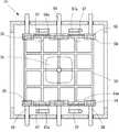
图2是表示本发明涉及的处理装置的结构例的俯视图。FIG. 2 is a plan view showing a configuration example of a processing apparatus according to the present invention.
图3是表示支承托盘的承载体的结构的图2的A-A线截面图。Fig. 3 is a cross-sectional view along line A-A of Fig. 2 showing the structure of a carrier supporting the tray.
图4是表示承载体与小齿轮的配置关系的图2的B-B线截面图。Fig. 4 is a sectional view taken along line B-B in Fig. 2 showing the arrangement relationship between the carrier and the pinion.
图5是向处理室输入承载体的状态的俯视图。Fig. 5 is a plan view of a state in which a carrier is carried into a processing chamber.
图6是表示承载体、升降杆、托盘、升降台的位置关系的图2的C-C线位置的侧视图。Fig. 6 is a side view at the line C-C of Fig. 2 showing the positional relationship among the carrier, the elevating rod, the tray, and the elevating platform.
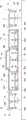
图7是表示处理装置的动作的时序图。FIG. 7 is a sequence diagram showing the operation of the processing device.
图8是表示本发明涉及的处理装置的其他结构例的俯视图。8 is a plan view showing another configuration example of the processing apparatus according to the present invention.
图9是处理装置的其他结构例的正视图。Fig. 9 is a front view of another configuration example of the processing device.
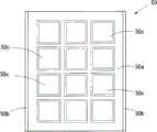
图10A是托盘的俯视图,图10B是托盘的侧视图。FIG. 10A is a top view of the tray, and FIG. 10B is a side view of the tray.
图11是表示处理室内中的结构的侧视图。Fig. 11 is a side view showing the structure inside the processing chamber.
图12是表示使托盘上升至处理位置后的状态的侧视图。Fig. 12 is a side view showing a state in which the tray has been raised to the processing position.
具体实施方式Detailed ways
以下根据附图来说明本发明的优选实施方式。Preferred embodiments of the present invention will be described below with reference to the drawings.
(处理装置的整体结构及其作用)(The overall structure and function of the processing device)
图1示出本发明涉及的处理装置的整体结构。此处理装置在处理室10的两侧以夹着处理室10的配置的方式配置第一负载锁定室12与第二负载锁定室14,串联配置处理室整体。FIG. 1 shows the overall structure of a processing device according to the present invention. In this processing apparatus, a first
在第一负载锁定室12的端部、第一负载锁定室12与处理室10之间的分隔部、处理室10与第二负载锁定室14的分隔部、第二负载锁定室14的端部上分别设置有闸阀16a、16b、16c、16d。At the end of the first
对第一负载锁定室12与第二负载锁定室14分别附加设置有真空装置18、19,来进行真空排气以及放气(air release)操作。对处理室10附加设置控制供给成膜用气体、成膜等处理的处理控制部20。此外,处理室10中的处理内容并不仅限于成膜处理。另外,附加设置作为处理装置整体的控制部22来进行工件(work)的输送控制、闸阀16a~16d的开闭控制、真空装置18、19的驱动控制、处理控制部20的控制等。The first
图1中示出了本发明的处理装置中的特征性工件输送方式。首先,参考图1来说明本发明中的工件的处理方法。FIG. 1 shows a characteristic way of conveying workpieces in the processing apparatus of the present invention. First, the workpiece processing method in the present invention will be described with reference to FIG. 1 .
本发明的处理装置中的特征性结构是处理装置的一端部与另一端部双方是工件的输入口也是输出口,换句话说,在处理室10上设置第一供给排出口与第二供给排出口两个工件供给排出口,第一供给排出口与第二供给排出口两者用于工件的输入与输出。也就是说,从第一供给排出口输入到处理室10的工件在处理室中被处理后从第二供给排出口输出,相反地,从第二供给排出口输入到处理室10的工件在处理后从第一供给排出口输出。The characteristic structure in the processing device of the present invention is that both the one end and the other end of the processing device are the input port and the output port of the workpiece, in other words, the first supply and discharge port and the second supply discharge port are set on the processing chamber The outlet has two workpiece supply and discharge ports, both the first supply and discharge port and the second supply and discharge port are used for input and output of workpieces. That is to say, the workpiece input into the
在图1中,在处理装置的一端侧即第一负载锁定室12侧,首先将未处理的工件30输入至第一负载锁定室12,在第一负载锁定室12中被真空排气,然后,被输入至处理室10,在处理室10中实施所需的处理。处理后的工件30a被输入至第二负载锁定室14,放气,从处理装置输出。In FIG. 1 , at one end side of the processing apparatus, that is, the first
另一方面,从处理装置的另一端侧即第二负载锁定室14侧也将未处理的工件32输入至第二负载锁定室14,并从第二负载锁定室14输入至处理室10,实施规定的处理。处理后的工件32a被输入至第一负载锁定室12,放气,并从处理装置输出。此外,虽然为了说明工件的操作,以从处理装置的一侧供给工件30,从另一侧供给工件32的情况为例进行了说明,但工件30、32是同一制品。On the other hand, the unprocessed workpiece 32 is also input into the second
如上所述,虽然在本装置中将未处理的工件30、32分别从处理装置的一侧与另一侧输入并处理,但是此时,在处理室10与第一负载锁定室12之间、处理室10与第二负载锁定室14之间转移工件的操作是使两个工件以一次交叉的方式输送,上述这点是特征点。As described above, although the
也就是说,将在第一负载锁定室12与处理室10之间将未处理的工件30输入处理室10的操作、与将处理后的工件32a从处理室10输出至第一负载锁定室12的操作设定作为一步操作。That is, the operation of inputting the
第二负载锁定室14与处理室10之间也是同样的。将处理后的工件30a从处理室10输出至第二负载锁定室14的操作、与从第二负载锁定室14将未处理的工件32输入处理室10的操作设定作为一步操作。The same applies between the second
如上所述,以更换方式输送未处理的工件30、32与处理完毕的工件32a、30a的操作具体通过以下方法来实现,即、构成为在输送工件的承载体中设置上下两层支承架,且能在上层与下层支承架上各自支承工件,并且,将未处理的工件30、32与处理完毕的工件32a、30a分别放置在不同的支承架上。将在后面对承载体的具体结构进行描述。As mentioned above, the operation of transporting the
在从第一负载锁定室12将工件30输入至处理室10的操作完毕的状态下,将处理完毕的工件32a输出至第一负载锁定室12并关闭闸阀16b,对第一负载锁定室12进行放气,然后,从第一负载锁定室12输出处理完毕的工件32a。在输出处理完毕的工件32a后,将后续的未处理的工件30装载在承载体上,并进行下次的工件30的供给操作。在第二负载锁定室14中也是同样的,通过向处理室10输入未处理的工件32,并输出处理后的工件30a的操作,从而在第二负载锁定室14留下处理后的工件30a,然后关闭闸阀16c,对第二负载锁定室14放气,从第二负载锁定室14输出处理后的工件30a。接下来,将后续的未处理的工件32支承在承载体上,进行下次的工件32的供给操作。In the state where the
这样,从处理装置的一侧将未处理的工件30输入至处理装置,通过处理装置后从另一侧输出处理后的工件30a,此外,从处理装置的另一侧将未处理的工件32输入至处理装置,通过处理装置从一方侧输出处理后的工件32a。Thus, an
在此处理操作中,由于交替地进行从第一负载锁定室12向处理室10供给未处理工件30的操作、与从第二负载锁定室14向处理室10供给未处理的工件32的操作并处理工件30、32,所以如果从处理装置的一个供给侧来看的话,在处理室10中每进行两次处理只需供给一次工件即可。也就是说,与对处理室10中的每次处理操作都供给工件的现有方法相比,用于供给准备工件的时间被延长至两倍。In this processing operation, since the operation of supplying the
如上所述,根据本实施方式的处理方法,即使在处理室10中处理时间较短的情况下,供给工件的时间上也有富余,且可回避由于供给工件所需的时间而限制处理装置的间隔时间(tact time),从而能使处理室10高效地运作以进行生产处理。As described above, according to the processing method of this embodiment, even if the processing time in the
(处理装置的结构)(Structure of processing device)
图2示出作为本发明涉及的处理装置的例子,示出了构成为在太阳能电池板的表面成膜防止反射膜的装置的例子。FIG. 2 shows an example of a device configured to form an antireflection film on the surface of a solar cell panel as an example of a processing device according to the present invention.
与上述的实施方式相同,本实施方式的处理装置构成为以夹着处理室10配置的方式串联配置第一负载锁定室12与第二负载锁定室14,并分别与第一负载锁定室12和第二负载锁定室14相邻接地配置第一进出口40与第二进出口42。Similar to the above-mentioned embodiment, the processing apparatus of this embodiment is configured such that the first
第一负载锁定室12及第二负载锁定室14可通过关闭闸阀16a~16d变为与外部分隔的封闭空间。在第一负载锁定室12及第二负载锁定室14上分别连接有真空装置(未图示)。The first
在本处理装置中,在托盘50上支承工件80,并将工件80与托盘50一起输送至处理室10,从而进行所需的处理。In this processing apparatus, the
为了便于说明,在图2中示出向第一负载锁定室12、第二负载锁定室14、处理室10及第一进出口40、第二进出口42移动托盘50的状态。For convenience of description, FIG. 2 shows a state in which the
托盘50被形成为格子状,使其能支承以4×4的排列配置的16个工件80。此外,在只有一个工件却是大块工件的情况下也能进行输送而不用托盘。The
本实施方式的处理装置中的特征性的结构之一在于,输送托盘50的承载体54被设置成能在上位置与下位置的上下分离的位置上支承托盘50。One of the characteristic structures in the processing apparatus of this embodiment is that the
图3示出从A-A线截面方向观察在第一进出口40中支承托盘50的承载体54的结构的状态。将承载体54形成为其长度与托盘50的前后方向的宽度大致相同且侧面形状为“··”形的条状。在承载体54上设置上部架55与下部架56作为支承与托盘50的输送方向平行的两侧缘的支承架。在上部架55与下部架56分别支承托盘50时,在上下方向上以隔开互不干涉的间隔的方式设置托盘50。FIG. 3 shows a view of the structure of the
工件80在被托盘50支承的状态下与承载体54一起移动至第一负载锁定室12、处理室10、第二负载锁定室14。因此,通过较窄地设定上部架55与下部架56之间的间隔,从而可缩小第一负载锁定室12、第二负载锁定室14的内部容积,可缩短真空排气等动作所需要的时间,并可缩短用于输送的准备时间。The
承载体54在通过齿轨/小齿轮结构维持在水平高度位置的状态下,以可沿输出输入方向往复移动的方式被支承。The
在承载体54的下部架56的下面,以跨越承载体54的侧缘的全长的方式形成有齿轨(rack)56a、在承载体54的下面配置有与齿轨56a结合的小齿轮58。齿轨/小齿轮结构适于使承载体54的水平高度位置保持为一定以进行输送的操作,具有能正确地达到输送位置的优点。但输送承载体54的结构并不仅限于齿轨/小齿轮结构。Under the
如图2所示,小齿轮58配置为在处理装置中的承载体54的输送方向上等间隔地、具体地说在承载体54的侧缘上的三个位置上支承承载体54。作为整个处理装置,小齿轮58被配置在同一高度位置,通过小齿轮58与承载体54的齿轨56a结合,从而在各室之间一边转移承载体54一边移动。在小齿轮58上连接有旋转驱动结构(未图示),其用于控制各小齿轮的旋转驱动结构并控制承载体54的输送。As shown in FIG. 2 , the
在图3中,在承载体54的侧方位置配置有构成支承托盘50的支承单元的升降杆57。在升降杆57的上端部设置有与托盘50的下面结合的钩子57a。在升降杆57上,在钩子57a旋转至托盘50的内侧并与托盘50结合的位置、与钩子57a旋转至托盘50侧方的退避位置且不与托盘50结合的位置之间,附加设置有使其绕升降杆57的轴线旋转的旋转结构(未图示)。In FIG. 3 , lift
图3示出在将升降杆57下降至下位置并将钩子57a旋转至托盘50的内侧的状态下,钩子57a位于承载体54的上部架55与下部架56的中间的高度位置的状态。在承载体54上设置切口54a,以便当钩子57a旋转时承载体54与钩子57a不干涉,且当钩子57a超过上部架55并上升至上位置时承载体54与钩子57a不干涉。3 shows a state in which the
图3示出在承载体54的下部架56支承托盘50的状态。在下部架56上支承托盘50的状态相当于在托盘50上放置未处理的工件80,在承载体54上支承托盘50并向第一负载锁定室12输入工件80的状态。FIG. 3 shows a state where the
并且,在图3中,在承载体54的上部架55上支承托盘50的状态相当于在托盘50上支承处理后的工件80a的状态。In addition, in FIG. 3 , the state where the
也就是说,承载体54的下部架56是未处理的工件80的供给位置,承载体54的上部架55是处理后的工件80a的输出位置。That is, the
图4是图2中B-B线位置中的、承载体54与小齿轮58的配置位置关系的侧视图。图4是支承工件80的托盘50与承载体54一起被输入的状态。承载体54与小齿轮58啮合并被支承,通过旋转驱动小齿轮58被水平地输入第一负载锁定室12。第一负载锁定室12在输入未处理的工件80时被进行真空排气处理,在从处理室10输出处理后的工件80a时进行放气处理。承载体54的上部架55支承处理后的工件80a。在第一负载锁定室12的侧面设置被闸阀16b封闭的开口部161。FIG. 4 is a side view showing the positional relationship between the
图5是将支承托盘50的承载体54输入至处理室10的状态的俯视图。用承载体54支承与托盘50的输送方向平行的两侧缘,并由小齿轮58从下面侧支承承载体54。在承载体54上设置切口54a,设置在升降杆57上的钩子57a在位于承载体54的外侧的退避位置与旋转至承载体54的内侧的结合位置之间自由旋转,且能超过上部架55移动至上位置。FIG. 5 is a plan view of a state in which the
另外,承载体54从第一负载锁定室12移动至处理室10后,与支承了处理后的工件80a的托盘一起返回移动至第一负载锁定室12。配置在处理室10中央的升降台70被设置为可在下位置与上位置之间升降。In addition, after the
图6是图2的C-C线位置上的承载体54、升降杆、托盘50及升降台70的位置关系的侧视图。升降台70构成移动单元,其使通过承载体54输入的托盘50从下部架56上升至进行成膜处理的上位置并加以支承。FIG. 6 is a side view showing the positional relationship of the
升降杆57构成移载单元,其在承载体54的上部架55的稍上面从升降台70接受在上位置被处理的托盘50,然后放置在承载体54的上部架55。The elevating
在上述说明中,已经对配置在图2所示的处理装置的一侧的第一进出口40与第一负载锁定室12进行了说明,配置在处理装置的另一侧的第二进出口42与第二负载锁定室14的结构也与第一进出口40及第一负载锁定室12中的结构完全相同。In the above description, the first inlet and
在第一进出口40、第二进出口42上配置有用于升降托盘50的升降台72。升降台72在承载体54的上部架55与下部架56的中间位置、与承载体54的下位置之间被升降驱动。A lift table 72 for lifting and lowering the
另外,在第一进出口40、第二进出口42上配置有沿与承载体54的输送方向正交的方向延伸的导轨74,并设置有沿导轨74进行进退移动的移动框75。在移动框75上,与工件80在托盘50中的一列上的配置数及配置位置相符合地设置吸附支承工件80的吸附垫76。吸附垫76与空气吸附装置(未图示)连接。In addition,
在导轨74的端部侧,使与工件80在托盘50上的配置位置相符合地配置有排列并收容未处理的工件80的工件的供给部D、以及收容处理后的工件80a的收容部E。On the end side of the
(处理装置的动作)(action of processing device)
接下来,主要参考图2来说明通过本实施方式的处理装置来处理工件80的操作。Next, the operation of processing the
首先,在第一进出口40,放置有未处理的工件80的托盘50在被承载体54的下部架56支承的状态下(图3)开始动作。承载体54的上部架55处于空置状态。First, at the first inlet and
在开放闸阀16a并封闭闸阀16b的状态下,将托盘50与承载体54一起输入第一负载锁定室12。通过上述的齿轨/小齿轮机构进行此输入操作。In the state where the
在向第一负载锁定室12输入支承托盘50的承载体54后,封闭闸阀16a并对第一负载锁定室12进行真空排气。After the
在第一负载锁定室12达到规定的真空度且处理室10中的处理结束时,打开闸阀16b,并将放置了工件80的托盘50与承载体54一起输入处理室10。When the first
在处理室10中,通过作为移动单元的升降台70将托盘50支承在上位置的状态下进行成膜处理,成膜处理完毕后,下降升降台70,此时将托盘50从升降台70转移至作为移载单元的升降杆57。如图6所示的中心线(p-p′线)的右半部所示,在升降杆57的钩子57a位于承载体54的上部架55的上位置时,转移托盘50,并变为等待承载体54进入的状态。升降台70下降至承载体54的下位置。In the
在处理室10中的成膜处理后,托盘50与承载体54一起从第一负载锁定室12进入处理室10的状态变为如图6所示在承载体54的下部架56上支承放置有未处理的工件80的托盘50、在承载体54的上面通过升降杆57支承支承有处理后的工件80a的托盘50的状态。After the film-forming process in the
升降杆57由此状态下降,将放置有处理后的工件80a的托盘50从升降杆57转移至承载体54的上部架55。升降杆57下降至下位置后,在承载体54移动时,向外旋转钩子57a使得钩子57a与承载体54互不干涉。The elevating
同时,上升位于承载体54的下位置的升降台70,并将被下部架56支承的托盘50提升至下部架56与上部架55的中间位置并在该位置停止。Simultaneously, the elevating table 70 located at the lower position of the
在此状态下,使承载体54从处理室10移动至第一负载锁定室12。在进行这个返回移动操作时,在承载体54的上部架55上支撑有放置了处理后的工件80a的托盘50,并从下部架56取出放置了未处理的工件80的托盘50,下部架56变为空置位置。In this state, the
在处理室10中,托盘50从被升降台70支承在中间位置的状态提升至进行成膜处理的上位置,并在上位置进行所需的成膜处理。In the
在本处理装置中,通过从第二负载锁定室14供给放置了未处理的工件80的托盘50来进行从第一负载锁定室12向处理室10供给放置了未处理的工件80的托盘50的操作的后续供给操作。In this processing apparatus, the
从第二负载锁定室14向处理室10供给新放置了未处理的工件80的托盘50,并将放置了处理后的工件80a的托盘50供给至承载体54的操作与上述的方法完全相同。在这种情况下,从处理室10向第二负载锁定室14输出的托盘50是通过先前的操作从第一负载锁定室12向处理室10供给并进行处理的支承工件80a的托盘50。The operation of supplying the
也就是说,从第一负载锁定室12供给的放置了工件80的托盘50经过处理室10中的处理操作后被输出至第二负载锁定室14,并从第二负载锁定室14向处理室10供给的放置了工件80的托盘50在处理后被输出至第一负载锁定室12。That is, the
向第一负载锁定室12输出的放置了处理后的工件80a的托盘50在封闭闸阀16b后,对第一负载锁定室12放气,从第一负载锁定室12输出到第一进出口40。After the
在第一进出口40,对区别于从第一负载锁定室12输出的托盘50的其他托盘50进行预先放置未处理的工件80的操作。该操作通过以下方式进行:在作为放置单元的升降台72支承托盘50的状态下,通过从工件80的供给部D以每列四次的方式向托盘50供给工件80。沿着导轨74使移动框75在供给部D与托盘50上之间移动,并通过吸附垫76进行吸附支承,从而移载工件80。At the first entrance/
在将托盘50与承载体54一起从第一负载锁定室12输出至第一进出口40时,供给用的放置了未处理的工件80的托盘50被升降台72支承在承载体54的上部架55与下部架56的中间的高度。因此,通过承载体54移动至第一进出口40的动作,放置了未处理的工件80的托盘50进入承载体54的上部架55与下部架56之间。在此状态下,使升降台72移动至下位置,从升降台72向承载体54的下部架56转移新的托盘50。When the
另一方面,对于向第一进出口40输出的被承载体54的上部架55支承的放置了处理后的工件80的托盘50,在承载体54移动至导轨74的侧方位置时,使升降杆57的钩子57a进入上部架55与下部架56的中间位置,使升降杆57上升并在与承载体54分离的上方位置支承托盘50。On the other hand, for the
由于通过此操作在承载体54上仅在下部架56支承托盘50,所以在此状态下,将托盘50与承载体54一起输入第一负载锁定室12。向第一负载锁定室12输入托盘50后的操作如上所述。Since the
由于在被升降杆57支承的托盘50上放置处理后的工件80a,所以再使升降杆57下降至工件80a的移载位置并将托盘50从升降杆57转移至升降台72。在此状态下,使移动框75在导轨74上进行往复移动并将处理后的工件80a从托盘50移载至收容部E。Since the processed
从托盘50将处理后的工件80a移载至供给部E后,接下来,从工件80的供给部D将未处理的工件80移载至托盘50。After the processed
在托盘50与供给部D及收容部E之间,移载未处理的工件80与处理后的工件80a时的托盘50的高度设置在承载体54的上部架55与下部架56的中间位置,并向托盘50移载工件80,完成后,通过从第一负载锁定室12输出承载体54来在承载体54的上部架55与下部架56之间插入托盘50。Between the
在将托盘50移动至处理室10到返回至第一进出口40期间,进行向托盘50替换装载未处理的工件80与处理后的工件80a的操作即可。During the period from moving the
第二进出口42中的工件80、80a的移载操作也与第一进出口40中的移载操作完全相同。The transfer operation of the
也就是说,通过向第二进出口42输出承载体54的操作,将放置了未处理的工件80的新托盘50转移至承载体54的下部架56并输送至第二负载锁定室14,在第二进出口42将处理后的工件80a从被升降杆57支承并残留的托盘50移载至收容部E,接下来从供给部D将未处理的工件80移载至托盘50并准备下次的供给操作。That is to say, through the operation of outputting the
(时序图)(timing diagram)
图7是有关本实施方式的处理装置的动作的时序图。图7中示出从第一进出口40与第二进出口42开始输入工件的时刻开始的动作。实线箭头表示从第一进出口40供给的工件,虚线箭头表示从第二进出口42供给的工件。FIG. 7 is a timing chart related to the operation of the processing device of this embodiment. FIG. 7 shows the operation starting from the moment when the first inlet and
首先,从第一进出口40向第一负载锁定室12输入工件,对第一负载锁定室12真空排气后,输入处理室10并开始处理。First, the workpiece is loaded into the first
另一方面,从第二进出口42延迟若干定时(timing)并向第二负载锁定室14输入工件,对第二负载锁定室14真空排气,并准备从第二负载锁定室14向处理室10输送工件。On the other hand, some timing (timing) is delayed from the second inlet and
一旦处理室10中的工件处理结束,将处理后的工件与从第二负载锁定室14供给的工件进行交换并向第二负载锁定室14输出。实线箭头与虚线箭头的交叉表示将处理后的工件从处理室10输出并将未处理的工件输入处理室10的操作。Once the processing of the workpiece in the
由第二负载锁定室14供给的工件在处理室10内开始处理。Workpieces supplied by the second
另一方面,从处理室10输出至第二负载锁定室14的处理后的工件通过第二负载锁定室14与第二进出口42之间的交换装载操作被收容至第二进出口42。此外,通过此操作,第二进出口42进入输入后续工件的准备状态。On the other hand, the processed workpieces output from the
另一方面,先前从第二负载锁定室14供给至处理室10的工件在处理室10内处理后与从第一负载锁定室12输入的工件进行交换。通过此交换操作在处理室10中留下从第一负载锁定室12输入的工件,并将在处理室10中处理的工件转移至第一负载锁定室12。On the other hand, the workpiece previously supplied from the second
转移至第一负载锁定室12的工件通过第一进出口40与第一负载锁定室12之间的交换装载操作被收容至第一进出口40。此外,通过此操作,第一进出口40变为输入后续工件的准备状态。The workpiece transferred to the first
如上所述,在第一进出口40与第二进出口42中,使工件的供给定时错开每个半周期地依次供给工件,此外同时接受处理完毕的工件。从图7可知,从第一进出口40供给的工件被输出至第二进出口42,相反地,从第二进出口42供给的工件被输出至第一进出口40。As described above, in the first inlet and
图示例的时序图是设定为处理室10中的处理时间为25秒且交换操作是10秒的例子。在此情况下,处理室10的周期时间变为35秒。在只从一个方向对处理装置供给工件的现有方法的情况下,为了将处理室10的周期时间维持在35秒,必须每35秒就准备供给下一工件。与此相对,在本实施方式的处理装置的情况下,在第一进出口40及第二进出口42,每70秒进行供给下一工件的准备即可。The timing chart of the illustrated example is an example in which the processing time in the
如上所述,根据本实施方式的处理装置的结构,由于能将供给工件所需的时间延长至两倍,因而能有效地被用于处理室10中的处理时间(周期时间)缩短且工件的供给操作超出处理室10的周期时间的情况。在对本实施方式的太阳能电池用板的表面成膜防止反射膜的情况下,由于膜厚为0.8μm左右所以成膜所需时间为20秒~50秒左右。在这样的短时间的处理的情况下,本发明的处理装置的结构特别有效,且对提高生产效率极为有效。As described above, according to the structure of the processing apparatus of the present embodiment, since the time required for supplying the workpiece can be doubled, the processing time (cycle time) that can be effectively used in the
如上所述,本实施方式的处理装置中使用的输送系统的结构简单,无需复杂的结构,在这一点上也有利。As described above, the conveyance system used in the processing apparatus of this embodiment is also advantageous in that it does not require a complicated structure and has a simple structure.
此外,不一定限于处理室10中的处理时间短的情况,也能有效地利用于制造供给工件的操作需要比较长时间这样的产品的情况。通过使供给工件的周期时间有富余,从而能可靠且稳定地供给工件,从而可进行可靠性高的处理。此外,能使用容量小且处理性能低的真空装置,并可减少装置的制造成本。In addition, it is not necessarily limited to the case where the processing time in the
另外,在上述实施方式中,示出了作为处理装置的一例,具体的结构可以有各种变化。例如虽然在上述实施方式中承载体54被形成为条状体,但承载体54的方式能进行各种变形。此外,虽然对承载体54具有通过齿轨/小齿轮机构进行输送的结构进行了说明,但并不仅限于此。此外,也可适当地选择升降杆57、升降台70的方式、第一进出口40及第二进出口42中的工件80的供给、输出结构。In addition, in the above-mentioned embodiment, an example of a processing device was shown, and various changes are possible in a specific structure. For example, although the
(处理装置的其他结构例)(Other structural examples of processing equipment)
图8示出了上述处理装置的其他结构例。本实施方式的处理装置也与上述处理装置相同,构成为以夹着处理室10配置的方式配置了第一负载锁定室12与第二负载锁定室14。此外,与第一负载锁定室12、第二负载锁定室14邻接地,在第一负载锁定室12、第二负载锁定室14之间配置有进出工件80的第一进出口40与第二进出口42。在图8中,对与上述处理装置相同的结构、例如闸阀16a~16d、升降台70、72等标注了相同的标号。FIG. 8 shows another configuration example of the above processing device. The processing apparatus according to the present embodiment is also configured such that a first
在本实施方式的处理装置中,处理工件80时托盘50的基本输送动作与上述处理装置中的托盘50的输送动作相同。也就是说,从第一供给排出口向处理室10输入的未处理的工件80在处理室10中被处理后从处理室10的第二供给排出口输出,相反地,从第二供给排出口输入到处理室10的未处理的工件80在处理室10中被处理后从第一供给排出口输出。也就是说,支承未处理的工件80的托盘50与支承处理后的工件80的托盘50在通过处理室10时,一边交叉移动一边进行输入输出。In the processing apparatus of this embodiment, the basic transport operation of the
本实施方式的处理装置中的特征性结构在于,与在上述处理装置(图2)中利用承载体54输送托盘50的情况相对,在本处理装置中,上下两层地配置输送辊作为托盘50的输送机构,而不使用承载体54,将未处理的工件80与处理后的工件80向交叉方向输送并给排。The characteristic structure in the processing apparatus of this embodiment is that, as opposed to the case where the
图9示出从正面方向观察处理装置的状态。如图9所示,跨越整个第一进出口40、第一负载锁定室12、处理室10、第二负载锁定室14、第二进出口42,分上下两层地配置输送辊90a~94b。在图9中示出上下的输送辊中的前侧输送辊90a、90b、92a、92b、94a、94b。Fig. 9 shows a state in which the processing device is viewed from the front direction. As shown in FIG. 9 ,
下层输送辊90a、92a、94a与上层输送辊90b、92b、94b一起以使输送高度位置为水平的方式设定高度位置。The
在图8中示出了上下的输送辊中的下层输送辊90a、91a、92a、93a、94a、95a。与前侧输送辊90a、92a、94a相对且以隔开托盘50的宽度方向的间隔的方式在里侧配置输送辊91a、93a、95a。上层输送辊90b~95b也与下层输送辊90a~95a相同地配置。In FIG. 8, the
通过作为输送辊的驱动部的电动机M2,完全同步地旋转驱动在第一进出口40与第一负载锁定室12上配置的输送辊90a、91a、90b、91b。在本实施方式中,在第一进出口40与第一负载锁定室12上分别配置的下层十二个输送辊90a、91a连同上层十二个输送辊90b、91b共二十四个输送辊90a~91b被同步地旋转驱动。The conveying
在处理室10中,配置在处理室10中的下层六个输送辊92a、93a连同上层六个输送辊92b、93b(未图示)共十二个输送辊被同一电动机M1同步地驱动。In the
对于配置于第二进出口42与第二负载锁定室14的下层与上层输送辊94a~95b共二十四个输送辊也用同一电动机M3同步地旋转驱动。The same motor M3 is also used to synchronously rotate and drive the twenty-four conveying rollers of the lower and upper conveying
电动机M1根据托盘50的输送方向将输送辊旋转驱动至一方向与另一方向。The motor M1 rotationally drives the conveying rollers to one direction and the other direction according to the conveying direction of the
为了使前侧输送辊90a与里侧的输送辊91a同步地旋转,经由共用驱动轴连接前侧输送辊90a之一与内侧的处于相对位置的输送辊91a之一,对于其他的输送辊90a、91a经由滑轮与共用驱动轴连接即可。In order to make the front
为了使下层输送辊90a与上层输送辊90b同步地旋转,可以使安装在下层输送辊90a的旋转轴上的齿轮与安装在上层输送辊90b的旋转轴上的齿轮啮合安装。由此,下层与上层的输送辊90a、90b相互向相反的方向旋转,基于下层输送辊90a、91a与上层输送辊90b、91b的托盘50的输送方向(输送朝向)相反。其他输送辊92a~95b也可同样地连接。In order to rotate the lower conveying
在本实施方式中,夹着处理室10配置的一方的下层输送辊(90a、91a、92a、93a)与上层输送辊(90b、91b、92b、93b)构成第一输送机构,另一方的下层输送辊(92a、93a、94a、95a)与上层输送辊(92b、93b、94b、95b)构成第二输送机构。此外,设置有控制驱动这些输送辊的电动机M1、M2、M3的控制部。In this embodiment, one of the lower conveying rollers (90a, 91a, 92a, 93a) and the upper conveying rollers (90b, 91b, 92b, 93b) disposed across the
图10A、图10B示出在本实施方式的处理装置中使用的托盘50的例子。图10A是俯视图,图10B是从侧面方向观察的图(示出碳托盘(carbontray)50a的截面)。托盘50包括放置工件80的碳托盘50a与安装在碳托盘50a的两侧缘上的导轨50b。碳托盘50a上设置放置工件(例如太阳能电池板)80的放置凹部50c。10A and 10B show an example of the
如图10B所示,一方的输送辊90a使用具备凸缘901的辊体,托盘50的一方的导轨50b的下端缘由凸缘901引导,从而限定托盘50的输送方向。另一方的输送辊91a上未设置凸缘,这是为了不妨碍在处理时加热托盘50的热膨胀。As shown in FIG. 10B , a roller body provided with a flange 901 is used for one conveying
根据工件80来设定托盘50的结构、大小等。在仅以平板状大块形成的工件的情况下,可以不使用托盘50而仅用输送辊90a、91a来支承工件加以输送。对于其他的输送辊92a~95b也可同样地构成。另外,对于输送辊的结构,可以根据输送工件的大小或方式等来使用适宜结构的输送辊。The structure, size, and the like of the
图11示出了处理室10中输送辊92a、92b、93a、93b的安装例。如上所述,下层输送辊92a与上层输送辊92b通过与固定在各自的旋转轴96a、96b上的齿轮97a、97b啮合来连接。FIG. 11 shows an example of installation of
在本实施方式中,构成为配置在处理室10的上层的输送辊92b、93b能在托盘50的宽度方向(与托盘50被输送的方向正交的方向)移动。在输送辊92b、93b的旋转轴96b、96c上安装有O形环等密封材料,旋转轴96b、96d以真空密封在处理室10的间隔墙上的状态可沿轴线方向移动。In this embodiment, the
上层齿轮97b与旋转轴96b中,旋转轴96b的端部形成在花键轴98上,齿轮97b与花键轴98被设置成能沿旋转轴96b的轴线方向移动且旋转轴96b与齿轮97b能在圆周方向上一体地旋转。当然,旋转轴96b与齿轮97b的结合方法只要能沿轴线方向自如地移动且能在圆周方向上一体地旋转的方法即可,并不限于使用花键轴的方法。Among the
旋转轴96b与在轴线方向推动旋转轴96b的驱动部100相连接,旋转轴96c与驱动部101连接并被沿轴线方向推动。驱动部100、101等构成退避单元。The
另外,第一进出口40及第二进出口42中的上层输送辊90b、91b、94b、95b也与图11所示相同,成为能在与托盘50的输送方向正交的方向上移动输送辊90b、91b、94a、95b的结构。这些结构与图11所示的上层输送辊92b、93b的结构相同。In addition, the upper conveying
(处理装置的操作)(operation of processing device)
接下来,对通过本实施方式的处理装置处理工件80的动作进行说明。Next, the operation of processing the
首先,在第一进出口40,放置了未处理的工件80的托盘50被放置在下层输送辊90a、91a上。First, at the first inlet and
接着,驱动电动机M2并将托盘50输入至第一负载锁定室12。在正常动作下,向第一负载锁定室12输入托盘50时,从第一负载锁定室12向第一进出口40输出支承了处理后的工件80的托盘50。也就是说,在第一负载锁定室12与第一进出口40之间同步进行输入、输出托盘50的操作。Next, the motor M2 is driven and the
如上所述,由于下层输送辊90a、91a与上层输送辊90b、91b向相反方向旋转,所以通过电动机M2来驱动输送辊,从而上层与下层托盘50向相反方向移动,并可实现托盘50的输入、输出操作。As mentioned above, since the lower conveying
将第一负载锁定室12输入至托盘50后,关闭闸阀16a并对第一负载锁定室12真空排气。由此,变为可向处理室10输入未处理的工件80的状态。After the first
如果前处理中有关已输入至处理室10的工件80的处理完毕,则打开闸阀16b,同步地驱动电动机M1与电动机M2,向处理室10的下层输送辊92a、93b输入托盘(未处理工件)50,从处理室10的上层输送辊92b、93b向第一负载锁定室12的上层输送辊90b、91b转移托盘(处理后工件)50。If the processing of the
如果在下层与上层输送辊间转移托盘50,则关闭闸阀16b,并对第一负载锁定室12放气并驱动电动机M2,从第一负载锁定室12向第一进出口40输出托盘(处理后工件)50,同时从第一进出口40向第一负载锁定室12输入托盘(未处理工件)50。将支承处理后的工件80的托盘50通过上层输送辊90b、91b输出,并将支承未处理的工件80的托盘50通过下层输送辊90a、91a输入。If the
在处理室10与第一负载锁定室12之间输出输入托盘50的操作时,处理室10的升降台70位于下层输送辊92a、93a的下面。一旦托盘50输入至处理室10,通过升降台70将托盘50提升至上层输送辊92b、93b上面的处理位置。升降台70及升降升降台70的驱动部构成升降单元。During the operation of loading and unloading the
图12示出通过升降台70使托盘50上升至处理位置的状态。通过升降台70提升托盘50时,使上层输送辊92b、93b横向退避,以使托盘50不干涉输送辊92b、93b。通过驱动部100、101来进行输送辊92b、93b的移动。FIG. 12 shows a state in which the
在通过升降台70将托盘50支承在上位置的状态下对工件80实施所需的处理。Required processing is performed on the
在本实施方式中,与上述实施方式不同,不进行从承载体54向升降台70移载托盘50这样的操作。因此,如果向处理室10导入未处理的工件80,则立即关闭闸阀16b,可转移至通过升降台70提升托盘50的操作。In this embodiment, unlike the above-described embodiment, the operation of transferring the
在等离子成膜处理中,从关闭闸阀16b到向处理室10供给气体并使气体环境常态化需要10秒左右。因此,若在这一时间内使升降台70上升至处理位置,则移动升降台70的时间不会影响周期时间。In the plasma film formation process, it takes about 10 seconds from closing the
此外,在对工件80进行成膜处理等后,通过使升降台70直接装载托盘50并在使上层输送辊92b、93b返回输送位置(初始位置)的状态下,下降升降台70,从而可向上层输送辊92b、93b移载托盘50。在这种情况下,在进行等离子处理后,为了从处理室10中排出(清除)气体而需要10秒左右。因此,在此时间内将托盘50向上层输送辊92b、93b移载即可。In addition, after the film-forming process or the like is performed on the
输送辊92b的旋转轴96b通过花键轴98与齿轮97b结合,所以下层与上层输送辊92a、92b被维持在同步旋转的状态。The
从负载锁定室12输入至处理室10的未处理的工件80在处理室10中被处理后,被输出至第二负载锁定室14。在处理室10与第二负载锁定室14之间输出输入托盘50的操作与在处理室10与第一负载锁定室12之间输出输入托盘50的操作相同。此外,第二负载锁定室14与第二进出口42之间的托盘50的输出输入操作也与第一负载锁定室12与第一进出口40之间的托盘50的输出输入操作相同。The
因此,从第一负载锁定室12输入至处理室10的工件80在处理后被输出至第二负载锁定室14,相反地,从第二负载锁定室14输入至处理室10的工件80在处理后被输出至第一负载锁定室12。也就是说,使未处理的工件80与处理后的工件80在处理室10中交叉地移动来进行输出输入操作。Therefore, the
第一进出口40或第二进出口42中,从被上层输送辊90b、91b、94b、95b支承的托盘50处通过吸附垫76吸附支承工件80,使移动框75沿导轨74移动,同时,最终在收容部E收容处理后的工件80。In the first inlet and
随后从供给部D向托盘50供给未处理的80,在通过升降台72支承托盘50的状态下,使上层输送辊90b、91b、94b、95b移动至横向的退避位置并下降升降台72,将托盘50移载至下层输送辊90a、91a、94a、95a。通过该升降台72从上层输送辊向下层输送辊移载托盘50的操作与使用承载体54的方法相比,能够缩短输送时间。Then, the unprocessed 80 is supplied from the supply part D to the
另外,在第一进出口40及第二进出口42,将处理后的工件80收容至收容部E,将未处理的工件80供给至新托盘50的方法可为各种方法,并不仅限于上述的方法。例如也可以是如下的方法:准备多个输送用的托盘50,准备未处理的工件80使其事先排列在托盘50上,根据输送操作依次供给这些托盘50。In addition, in the first inlet and
此外,在本实施方式中,虽然对通过下层输送辊供给未处理的工件且通过上层输送辊供给处理后的工件的结构进行了说明,与此相反,也可以是通过下层输送辊供给处理后的工件并通过上层输送辊供给未处理的工件的结构。在这种情况下,可以在处理室10中使托盘50从上层输送辊上升至处理位置,处理后,使处理后的托盘下降至下层输送辊的位置。In addition, in this embodiment, although the structure in which the unprocessed workpiece is fed by the lower conveying roller and the processed workpiece is fed by the upper conveying roller has been described, on the contrary, the processed workpiece may be fed by the lower conveying roller. The structure of the workpiece and feed the unprocessed workpiece through the upper conveying roller. In this case, in the
(周期时间)(period time)
如上所述,在本实施方式的处理装置中,可通过省略在与承载体54间移载托盘50的操作来缩短在与处理室之间输出输入工件的操作所需要的时间。该输出输入操作是图7所示的时序图中交换操作的部分。As described above, in the processing apparatus of the present embodiment, the time required for loading and unloading workpieces to and from the processing chamber can be shortened by omitting the operation of transferring the
在现有的输送方法中,在与处理室之间输出输入工件时需要的时间如下所述。In the conventional transport method, the time required for transporting and inputting workpieces to and from the processing chamber is as follows.
(1)打开闸阀的时间:2秒(1) Time to open the gate valve: 2 seconds
(2)向处理室一起输入托盘与承载体的时间:4秒(2) The time to feed the tray and carrier together into the processing chamber: 4 seconds
(3)将未处理的托盘从承载体移载至升降台的时间(将处理后的托盘移载至承载体):4秒(3) Time to transfer the unprocessed pallet from the carrier to the lifting table (transfer the processed pallet to the carrier): 4 seconds
(4)将承载体从处理室输出的时间:3秒(4) Time to export the carrier from the processing chamber: 3 seconds
(5)关闭闸阀的时间:2秒(5) Time to close the gate valve: 2 seconds
这些一共为15秒。These add up to 15 seconds.
在本实施方式的处理装置中,在与处理室之间输入输出工件需要的时间如下所述。In the processing apparatus according to this embodiment, the time required for loading and unloading workpieces to and from the processing chamber is as follows.
(1)打开闸阀的时间:2秒(1) Time to open the gate valve: 2 seconds
(2)向处理室输入托盘并从处理室输出托盘的时间:4秒(2) Time to input trays into the processing chamber and output trays from the processing chamber: 4 seconds
(3)关闭闸阀的时间:2秒(3) Time to close the gate valve: 2 seconds
这些一共为8秒。These total 8 seconds.
与产品的处理内容有关,在太阳能电池的成膜处理的例中,从关闭处理室的闸阀到成膜处理并打开闸阀需要大约50秒(气体常态化:10秒、等离子处理:30秒、气体清除:10秒)。因此在本例中,在第一实施方式的处理装置的情况下,1周期时间是50秒+15秒=65秒,但是根据本实施方式的处理装置,缩短为50秒+8秒=58秒。在这种情况下,周期时间缩短10%左右。在大量生产品的情况下,提高10%的生产效率极为重要。此外,在工件的处理时间更短的处理的情况下,例如处理时间为30秒的情况下,周期时间的缩短率为15%左右。根据本实施方式的处理装置,通过从第一负载锁定室12与第二负载锁定室14交替地供给未处理的工件80来处理工件80的方法,即使在处理室10中工件80的处理时间较短的情况下,能从容地供给工件80,且可以防止供给工件的输送系统对生产性的制约,此外,通过使工件80的输送操作效率化能有效地提高生产率。Depending on the processing content of the product, in the case of the solar cell film formation process, it takes about 50 seconds from closing the gate valve of the process chamber to film formation process and opening the gate valve (gas normalization: 10 seconds, plasma treatment: 30 seconds, gas Clear: 10 seconds). Therefore, in this example, in the case of the processing device of the first embodiment, one cycle time is 50 seconds+15 seconds=65 seconds, but according to the processing device of the present embodiment, it is shortened to 50 seconds+8 seconds=58 seconds . In this case, the cycle time is reduced by around 10%. In the case of high-volume production, a 10% increase in production efficiency is extremely important. In addition, in the case of processing with a shorter processing time of the workpiece, for example, when the processing time is 30 seconds, the shortening rate of the cycle time is about 15%. According to the processing apparatus of this embodiment, the method of processing the
Claims (19)
Translated fromChineseApplications Claiming Priority (3)
| Application Number | Priority Date | Filing Date | Title |
|---|---|---|---|
| JP2008-078764 | 2008-03-25 | ||
| JP2008078764AJP5330721B2 (en) | 2007-10-23 | 2008-03-25 | Processing apparatus and processing method |
| PCT/JP2009/055818WO2009119580A1 (en) | 2008-03-25 | 2009-03-24 | Processing apparatus and processing method |
Related Child Applications (1)
| Application Number | Title | Priority Date | Filing Date |
|---|---|---|---|
| CN201210207818.1ADivisionCN102751158B (en) | 2008-03-25 | 2009-03-24 | Processing apparatus |
Publications (2)
| Publication Number | Publication Date |
|---|---|
| CN102046840A CN102046840A (en) | 2011-05-04 |
| CN102046840Btrue CN102046840B (en) | 2012-08-01 |
Family
ID=41114878
Family Applications (2)
| Application Number | Title | Priority Date | Filing Date |
|---|---|---|---|
| CN2009801190528AExpired - Fee RelatedCN102046840B (en) | 2008-03-25 | 2009-03-24 | Processing apparatus and processing method |
| CN201210207818.1AExpired - Fee RelatedCN102751158B (en) | 2008-03-25 | 2009-03-24 | Processing apparatus |
Family Applications After (1)
| Application Number | Title | Priority Date | Filing Date |
|---|---|---|---|
| CN201210207818.1AExpired - Fee RelatedCN102751158B (en) | 2008-03-25 | 2009-03-24 | Processing apparatus |
Country Status (4)
| Country | Link |
|---|---|
| EP (1) | EP2261391B1 (en) |
| KR (1) | KR101669685B1 (en) |
| CN (2) | CN102046840B (en) |
| WO (1) | WO2009119580A1 (en) |
Families Citing this family (9)
| Publication number | Priority date | Publication date | Assignee | Title |
|---|---|---|---|---|
| JP5330721B2 (en) | 2007-10-23 | 2013-10-30 | オルボテック エルティ ソラー,エルエルシー | Processing apparatus and processing method |
| JP5835722B2 (en)* | 2009-12-10 | 2015-12-24 | オルボテック エルティ ソラー,エルエルシー | Automatic ranking multi-directional serial processor |
| JP2011155156A (en)* | 2010-01-27 | 2011-08-11 | Muratec Automation Co Ltd | Article transport device |
| US8459276B2 (en) | 2011-05-24 | 2013-06-11 | Orbotech LT Solar, LLC. | Broken wafer recovery system |
| JP5765815B2 (en)* | 2012-01-12 | 2015-08-19 | 大成建設株式会社 | Transport system |
| JP6096905B2 (en)* | 2012-09-10 | 2017-03-15 | アプライド マテリアルズ インコーポレイテッドApplied Materials,Incorporated | Substrate processing system and method for moving a substrate |
| CN104620370B (en)* | 2012-09-10 | 2018-09-28 | 应用材料公司 | Base plate processing system and the method for handling substrate |
| CN104555514B (en)* | 2014-12-31 | 2018-05-15 | 东莞市科立电子设备有限公司 | Double-station multifunctional online plate separator with adjustable rails |
| JP7350029B2 (en)* | 2021-06-15 | 2023-09-25 | キヤノントッキ株式会社 | Transport equipment and film forming equipment |
Citations (1)
| Publication number | Priority date | Publication date | Assignee | Title |
|---|---|---|---|---|
| CN1755526A (en)* | 2004-09-30 | 2006-04-05 | 东京毅力科创株式会社 | Base plate processing system |
Family Cites Families (9)
| Publication number | Priority date | Publication date | Assignee | Title |
|---|---|---|---|---|
| JP2938160B2 (en)* | 1990-07-20 | 1999-08-23 | 東京エレクトロン株式会社 | Vacuum processing equipment |
| US5795399A (en)* | 1994-06-30 | 1998-08-18 | Kabushiki Kaisha Toshiba | Semiconductor device manufacturing apparatus, method for removing reaction product, and method of suppressing deposition of reaction product |
| JP3165348B2 (en)* | 1995-05-18 | 2001-05-14 | ワイエイシイ株式会社 | Plasma processing apparatus and operation method thereof |
| JP4204128B2 (en) | 1999-01-18 | 2009-01-07 | 東京応化工業株式会社 | Substrate transport apparatus and substrate transport method |
| US6558509B2 (en)* | 1999-11-30 | 2003-05-06 | Applied Materials, Inc. | Dual wafer load lock |
| JP2002203885A (en)* | 2000-12-27 | 2002-07-19 | Anelva Corp | Inter-back type substrate processing equipment |
| JP2002270880A (en) | 2001-03-14 | 2002-09-20 | Shin Etsu Handotai Co Ltd | Solar cell module and method of manufacturing the same |
| US20030003767A1 (en)* | 2001-06-29 | 2003-01-02 | Plasmion Corporation | High throughput hybrid deposition system and method using the same |
| JP4517595B2 (en)* | 2003-06-26 | 2010-08-04 | 東京エレクトロン株式会社 | Method for transporting workpieces |
- 2009
- 2009-03-24WOPCT/JP2009/055818patent/WO2009119580A1/enactiveApplication Filing
- 2009-03-24EPEP09725876.8Apatent/EP2261391B1/ennot_activeNot-in-force
- 2009-03-24KRKR1020107023727Apatent/KR101669685B1/ennot_activeExpired - Fee Related
- 2009-03-24CNCN2009801190528Apatent/CN102046840B/ennot_activeExpired - Fee Related
- 2009-03-24CNCN201210207818.1Apatent/CN102751158B/ennot_activeExpired - Fee Related
Patent Citations (1)
| Publication number | Priority date | Publication date | Assignee | Title |
|---|---|---|---|---|
| CN1755526A (en)* | 2004-09-30 | 2006-04-05 | 东京毅力科创株式会社 | Base plate processing system |
Also Published As
| Publication number | Publication date |
|---|---|
| CN102751158A (en) | 2012-10-24 |
| CN102046840A (en) | 2011-05-04 |
| KR101669685B1 (en) | 2016-10-27 |
| EP2261391A4 (en) | 2013-01-23 |
| CN102751158B (en) | 2015-05-20 |
| KR20100134062A (en) | 2010-12-22 |
| EP2261391A1 (en) | 2010-12-15 |
| EP2261391B1 (en) | 2017-11-15 |
| WO2009119580A1 (en) | 2009-10-01 |
Similar Documents
| Publication | Publication Date | Title |
|---|---|---|
| JP5613302B2 (en) | Work processing device | |
| CN102046840B (en) | Processing apparatus and processing method | |
| US6742977B1 (en) | Substrate processing device, substrate conveying device, and substrate processing method | |
| TWI451521B (en) | Substrate treating apparatus and substrate treating method | |
| TWI571953B (en) | Vacuum processing apparatus | |
| US6059507A (en) | Substrate processing apparatus with small batch load lock | |
| CN100543957C (en) | Substrate processing systems and methods | |
| JP2002516239A (en) | In-situ substrate transfer shuttle | |
| JP2007242648A (en) | Substrate processing apparatus | |
| JPH09223727A (en) | Semiconductor treating apparatus, substrate changing mechanism and changing method thereof | |
| CN100437963C (en) | Processing device system | |
| JP2005340425A (en) | Vacuum treatment device | |
| JP3554534B2 (en) | Substrate support mechanism and substrate exchange method for semiconductor processing apparatus, and semiconductor processing apparatus and substrate transfer apparatus | |
| JPH09205127A (en) | Carrying of substrate, substrate carrier device and treatment system | |
| JPH05326666A (en) | Conveyor | |
| KR100749005B1 (en) | Substrate plasticity apparatus | |
| JP2004221610A (en) | Semiconductor processing apparatus | |
| CN222715445U (en) | Coating device | |
| JPH08124916A (en) | Multi-chamber vacuum heat treatment system | |
| KR20140114281A (en) | Ion implantation apparatus and film formation apparatus | |
| JPS63153270A (en) | Mechanism for exchanging substrate in vacuum vessel | |
| JP2519853B2 (en) | Article heating device | |
| CN119546798A (en) | Coating device | |
| KR100565001B1 (en) | Flat panel display device manufacturing device | |
| JPH1073379A (en) | Work transfer device of heat treatment device |
Legal Events
| Date | Code | Title | Description |
|---|---|---|---|
| C06 | Publication | ||
| PB01 | Publication | ||
| C10 | Entry into substantive examination | ||
| SE01 | Entry into force of request for substantive examination | ||
| C14 | Grant of patent or utility model | ||
| GR01 | Patent grant | ||
| TR01 | Transfer of patent right | ||
| TR01 | Transfer of patent right | Effective date of registration:20220629 Address after:Israel Masao City Patentee after:ORBOTECH Ltd. Address before:California, USA Patentee before:Orbotech LT Solar, LLC | |
| TR01 | Transfer of patent right | ||
| TR01 | Transfer of patent right | Effective date of registration:20220908 Address after:California, USA Patentee after:Orbotech LT Solar LLC Address before:Israel Masao City Patentee before:ORBOTECH Ltd. Effective date of registration:20220908 Address after:California, USA Patentee after:KLA-TENCOR Corp. Address before:California, USA Patentee before:Orbotech LT Solar LLC | |
| CF01 | Termination of patent right due to non-payment of annual fee | ||
| CF01 | Termination of patent right due to non-payment of annual fee | Granted publication date:20120801 |