CN102046068A - Systems and methods for treating and preventing loss of visual acuity - Google Patents
Systems and methods for treating and preventing loss of visual acuityDownload PDFInfo
- Publication number
- CN102046068A CN102046068ACN2009801209399ACN200980120939ACN102046068ACN 102046068 ACN102046068 ACN 102046068ACN 2009801209399 ACN2009801209399 ACN 2009801209399ACN 200980120939 ACN200980120939 ACN 200980120939ACN 102046068 ACN102046068 ACN 102046068A
- Authority
- CN
- China
- Prior art keywords
- birefringent
- lens
- correction device
- vision correction
- polymers
- Prior art date
- Legal status (The legal status is an assumption and is not a legal conclusion. Google has not performed a legal analysis and makes no representation as to the accuracy of the status listed.)
- Granted
Links
Images


Classifications
- G—PHYSICS
- G02—OPTICS
- G02C—SPECTACLES; SUNGLASSES OR GOGGLES INSOFAR AS THEY HAVE THE SAME FEATURES AS SPECTACLES; CONTACT LENSES
- G02C7/00—Optical parts
- G02C7/02—Lenses; Lens systems ; Methods of designing lenses
- G02C7/04—Contact lenses for the eyes
- G02C7/047—Contact lens fitting; Contact lenses for orthokeratology; Contact lenses for specially shaped corneae
- C—CHEMISTRY; METALLURGY
- C08—ORGANIC MACROMOLECULAR COMPOUNDS; THEIR PREPARATION OR CHEMICAL WORKING-UP; COMPOSITIONS BASED THEREON
- C08G—MACROMOLECULAR COMPOUNDS OBTAINED OTHERWISE THAN BY REACTIONS ONLY INVOLVING UNSATURATED CARBON-TO-CARBON BONDS
- C08G75/00—Macromolecular compounds obtained by reactions forming a linkage containing sulfur with or without nitrogen, oxygen, or carbon in the main chain of the macromolecule
- C08G75/20—Polysulfones
- C08G75/23—Polyethersulfones
- C—CHEMISTRY; METALLURGY
- C08—ORGANIC MACROMOLECULAR COMPOUNDS; THEIR PREPARATION OR CHEMICAL WORKING-UP; COMPOSITIONS BASED THEREON
- C08G—MACROMOLECULAR COMPOUNDS OBTAINED OTHERWISE THAN BY REACTIONS ONLY INVOLVING UNSATURATED CARBON-TO-CARBON BONDS
- C08G75/00—Macromolecular compounds obtained by reactions forming a linkage containing sulfur with or without nitrogen, oxygen, or carbon in the main chain of the macromolecule
- C08G75/24—Polysulfonates
- C—CHEMISTRY; METALLURGY
- C09—DYES; PAINTS; POLISHES; NATURAL RESINS; ADHESIVES; COMPOSITIONS NOT OTHERWISE PROVIDED FOR; APPLICATIONS OF MATERIALS NOT OTHERWISE PROVIDED FOR
- C09K—MATERIALS FOR MISCELLANEOUS APPLICATIONS, NOT PROVIDED FOR ELSEWHERE
- C09K19/00—Liquid crystal materials
- C09K19/04—Liquid crystal materials characterised by the chemical structure of the liquid crystal components, e.g. by a specific unit
- C09K19/06—Non-steroidal liquid crystal compounds
- C09K19/08—Non-steroidal liquid crystal compounds containing at least two non-condensed rings
- C09K19/10—Non-steroidal liquid crystal compounds containing at least two non-condensed rings containing at least two benzene rings
- C09K19/24—Non-steroidal liquid crystal compounds containing at least two non-condensed rings containing at least two benzene rings linked by a chain containing nitrogen-to-nitrogen bonds
- C—CHEMISTRY; METALLURGY
- C09—DYES; PAINTS; POLISHES; NATURAL RESINS; ADHESIVES; COMPOSITIONS NOT OTHERWISE PROVIDED FOR; APPLICATIONS OF MATERIALS NOT OTHERWISE PROVIDED FOR
- C09K—MATERIALS FOR MISCELLANEOUS APPLICATIONS, NOT PROVIDED FOR ELSEWHERE
- C09K19/00—Liquid crystal materials
- C09K19/04—Liquid crystal materials characterised by the chemical structure of the liquid crystal components, e.g. by a specific unit
- C09K19/38—Polymers
- C09K19/3804—Polymers with mesogenic groups in the main chain
- C09K19/3809—Polyesters; Polyester derivatives, e.g. polyamides
- C—CHEMISTRY; METALLURGY
- C09—DYES; PAINTS; POLISHES; NATURAL RESINS; ADHESIVES; COMPOSITIONS NOT OTHERWISE PROVIDED FOR; APPLICATIONS OF MATERIALS NOT OTHERWISE PROVIDED FOR
- C09K—MATERIALS FOR MISCELLANEOUS APPLICATIONS, NOT PROVIDED FOR ELSEWHERE
- C09K19/00—Liquid crystal materials
- C09K19/04—Liquid crystal materials characterised by the chemical structure of the liquid crystal components, e.g. by a specific unit
- C09K19/40—Liquid crystal materials characterised by the chemical structure of the liquid crystal components, e.g. by a specific unit containing elements other than carbon, hydrogen, halogen, oxygen, nitrogen or sulfur, e.g. silicon, metals
- C09K19/406—Liquid crystal materials characterised by the chemical structure of the liquid crystal components, e.g. by a specific unit containing elements other than carbon, hydrogen, halogen, oxygen, nitrogen or sulfur, e.g. silicon, metals containing silicon
- C09K19/408—Polysiloxanes
- G—PHYSICS
- G02—OPTICS
- G02B—OPTICAL ELEMENTS, SYSTEMS OR APPARATUS
- G02B1/00—Optical elements characterised by the material of which they are made; Optical coatings for optical elements
- G02B1/04—Optical elements characterised by the material of which they are made; Optical coatings for optical elements made of organic materials, e.g. plastics
- G02B1/041—Lenses
- G02B1/043—Contact lenses
- G—PHYSICS
- G02—OPTICS
- G02B—OPTICAL ELEMENTS, SYSTEMS OR APPARATUS
- G02B1/00—Optical elements characterised by the material of which they are made; Optical coatings for optical elements
- G02B1/08—Optical elements characterised by the material of which they are made; Optical coatings for optical elements made of polarising materials
- G—PHYSICS
- G02—OPTICS
- G02C—SPECTACLES; SUNGLASSES OR GOGGLES INSOFAR AS THEY HAVE THE SAME FEATURES AS SPECTACLES; CONTACT LENSES
- G02C7/00—Optical parts
- G02C7/02—Lenses; Lens systems ; Methods of designing lenses
- G02C7/04—Contact lenses for the eyes
- G02C7/041—Contact lenses for the eyes bifocal; multifocal
- G02C7/042—Simultaneous type
- G—PHYSICS
- G02—OPTICS
- G02C—SPECTACLES; SUNGLASSES OR GOGGLES INSOFAR AS THEY HAVE THE SAME FEATURES AS SPECTACLES; CONTACT LENSES
- G02C7/00—Optical parts
- G02C7/02—Lenses; Lens systems ; Methods of designing lenses
- G02C7/06—Lenses; Lens systems ; Methods of designing lenses bifocal; multifocal ; progressive
- G—PHYSICS
- G02—OPTICS
- G02C—SPECTACLES; SUNGLASSES OR GOGGLES INSOFAR AS THEY HAVE THE SAME FEATURES AS SPECTACLES; CONTACT LENSES
- G02C7/00—Optical parts
- G02C7/12—Polarisers
- G—PHYSICS
- G02—OPTICS
- G02C—SPECTACLES; SUNGLASSES OR GOGGLES INSOFAR AS THEY HAVE THE SAME FEATURES AS SPECTACLES; CONTACT LENSES
- G02C2202/00—Generic optical aspects applicable to one or more of the subgroups of G02C7/00
- G02C2202/24—Myopia progression prevention
Landscapes
- Chemical & Material Sciences (AREA)
- Physics & Mathematics (AREA)
- Health & Medical Sciences (AREA)
- Ophthalmology & Optometry (AREA)
- General Physics & Mathematics (AREA)
- Optics & Photonics (AREA)
- Organic Chemistry (AREA)
- General Health & Medical Sciences (AREA)
- Engineering & Computer Science (AREA)
- Crystallography & Structural Chemistry (AREA)
- Materials Engineering (AREA)
- Polymers & Plastics (AREA)
- Medicinal Chemistry (AREA)
- Chemical Kinetics & Catalysis (AREA)
- Prostheses (AREA)
- Eyeglasses (AREA)
Abstract
Description
Translated fromChinese发明领域field of invention
本发明涉及治疗和预防视敏度丧失的系统和方法。更具体地,本发明涉及调整进入眼的光线的焦点来治疗和预防近视的系统和方法。The present invention relates to systems and methods for treating and preventing loss of visual acuity. More specifically, the present invention relates to systems and methods for treating and preventing myopia by adjusting the focus of light entering the eye.
发明背景Background of the invention
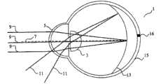
近视(也称为近视眼)是一种常见疾病。近视是眼的折射缺陷,其中图像在眼内部的玻璃体内而不是眼后方的视网膜上聚焦,导致近处的物体以清晰的分辨率呈现,而远处的物体则看起来模糊。近视状况如图1所示。如图所示,在轴(on-axis)光线9(平行于眼1中心轴7进入眼1的光线)和离轴光线11(以相对于中心轴7呈一定入射角进入眼并被角膜5和晶状体3折射入眼1的光线)形成聚焦区13。在近视患者中,进入眼的轴光的聚焦区13位于视网膜15前方,导致视敏度降低。聚焦区的曲率部分由角膜前表面和后表面的曲率决定,因此在不同患者中各不相同。Myopia (also known as nearsightedness) is a common condition. Myopia is a refractive defect of the eye in which images are focused in the vitreous body inside the eye rather than on the retina at the back of the eye, causing near objects to appear in sharp resolution while distant objects appear blurred. Myopia status is shown in Figure 1. As shown in the figure, on-axis rays 9 (rays entering the
常规的近视治疗技术通过改变角膜的折射状态调整在轴光线的焦点。如图2所示,这些技术将聚焦区13向后朝视网膜15的方向移动,使在轴光线9在位于视网膜15中心的中央凹16上聚焦。常规的近视治疗技术包括例如,非球形或多光线几何构造附着透镜(multi-radial geometry contact lens)、眼镜、角膜植入体、角膜曲率矫正术(采用附着透镜使前角膜的曲率变平)和各种折射外科手术方法,如LASIK、PRK和LASEK。Conventional myopia treatment techniques adjust the focus of axial rays by changing the refractive state of the cornea. As shown in FIG. 2 , these techniques move the
然而,这样的常规技术存在相关缺点。例如,继续参照图2,如果聚焦区13的曲率比视网膜15的曲率更平坦,则在治疗中央凹近视(foveal myopia)时聚焦区13的一部分会移到周边视网膜17后方,导致视网膜周边的图像分辨率降低。眼通过伸长引起离轴光线的焦点在周边视网膜上或前方聚焦来对周边散焦作出反应。虽然周边视网膜17的反应可达到将离轴光的焦点移到周边视网膜17前方的所需效果,但其同时会导致在轴光线的焦点在中央凹16外聚焦,由此降低视敏度。此外,矫正该散焦可启动另一轮周边散焦和眼伸长。However, such conventional techniques have associated disadvantages. For example, with continued reference to FIG. 2, if the curvature of the
具体而言,光学领域研究近期已确定,除中央凹以外,视网膜周边图像质量差可在近视发生的过程中起主要作用。在周边视网膜随时间感受不到清晰聚焦时(特别是在聚焦区位于视网膜后方时),眼会沿轴伸长以将离轴光线在视网膜上或前方聚焦。就这点而言,已证实周边视网膜的散焦是引起轴长度增加信号的主要原因。眼伸长增大角膜到视网膜的距离,导致更多的在轴光线在中央凹上或前方聚焦。对该效应的讨论见例如Smith等的美国专利第7,025,460号,题为“改变周边离轴焦点位置区相对曲率和其相对位置的方法和设备”(“Methods and Apparatuses for Altering Relative Curvature of Field and Positions of Peripheral,Off-Axis Focal Positions”)(“Smith”)。Specifically, research in the field of optics has recently established that, in addition to the fovea, poor image quality in the retinal periphery can play a major role in the development of myopia. When the peripheral retina does not perceive sharp focus over time (especially if the focal zone is located behind the retina), the eye elongates axially to focus off-axis rays on or in front of the retina. In this regard, defocusing of the peripheral retina has been shown to be primarily responsible for the increased axial length signal. Eye elongation increases the distance from the cornea to the retina, causing more on-axis rays to focus on or in front of the fovea. For a discussion of this effect see, e.g., U.S. Patent No. 7,025,460 to Smith et al., entitled "Methods and Apparatus for Altering Relative Curvature of Field and Positions of Peripheral, Off-Axis Focal Positions") ("Smith").
轴伸长的一个不利副作用是在轴光的焦点从中央凹处离开,导致先前治疗的中央凹近视复发。换言之,治疗中央凹近视的常规技术实际上可随时间引起患者的近视进展。An adverse side effect of axial elongation is that the focal point of the axial light moves away from the fovea, leading to recurrence of previously treated foveal myopia. In other words, conventional techniques for treating foveal myopia can actually cause a patient's myopia to progress over time.
为防止轴伸长,必须通过将离轴光线在视网膜上或前方聚焦来最大程度减少和/或消除提供给周边视网膜刺激生长的信号。为达到该目的,Smith公开了改变焦点平面形状的光学外科手术和治疗系统和方法,以将周边焦点平面保持在视网膜上或前方,同时附有改善在轴光线在中央凹处聚焦的方法。然而,Smith公开的系统的一个缺点是这些方法会改变非中心在轴光的焦点,使其不能在中央凹上聚焦。由于视力主要依赖于在中央凹上聚焦的光来达到精确的视敏度,不希望改变非中心离轴光的焦点使其离开中央凹。To prevent axial elongation, the signal to the peripheral retina to stimulate growth must be minimized and/or eliminated by focusing off-axis rays on or in front of the retina. To this end, Smith discloses optical surgical and therapeutic systems and methods for changing the shape of the focal plane to maintain the peripheral focal plane on or in front of the retina, with a method for improving the focusing of on-axis rays in the fovea. However, one disadvantage of the systems disclosed by Smith is that these methods alter the focus of off-centre on-axis light so that it does not focus on the fovea. Since vision relies primarily on focusing light on the fovea for precise visual acuity, it is undesirable to change the focus of non-central off-axis light away from the fovea.
因此,需要能够引起离轴光线在周边视网膜上或前方聚焦而不影响非中心在轴光线焦点的系统和方法。Accordingly, there is a need for systems and methods that can cause off-axis rays to focus on or in front of the peripheral retina without affecting the focus of off-axis rays.
发明概述Summary of the invention
尽管会在下文详细讨论本发明克服已知技术缺点的方式,但大体而言,本发明通过使进入眼的光的聚焦区变陡来预防视敏度丧失。Although the manner in which the present invention overcomes the disadvantages of known techniques will be discussed in detail below, in general terms the present invention prevents loss of visual acuity by steepening the focal zone of light entering the eye.
根据本发明的各示例性实施方式,提供近视控制系统。近视控制系统是引起离轴光线在周边视网膜上或前方聚焦而基本不改变在轴光线焦点的任何系统或装置,由此最大程度减少和/或预防近视进展。According to various exemplary embodiments of the present invention, a myopia control system is provided. A myopia control system is any system or device that causes off-axis rays to focus on or in front of the peripheral retina without substantially changing the focus of on-axis rays, thereby minimizing and/or preventing myopia progression.
在一个示例性实施方式中,本发明包括视力矫正透镜如附着透镜,其由具有取向平行或基本平行于眼中心轴的可极化键的双折射材料构成。合适的材料包括但不限于包含聚对苯二甲酸乙二酯、聚碳酸酯、聚砜、聚醚砜、聚苯乙烯、聚酯碳酸酯(poly(estercarbonates))、刚性棒状聚酰胺以及其中供体和受体取代基诱导大分子偶极矩和增强可极化性各向异性的聚合物的共聚物。In one exemplary embodiment, the invention includes a vision correcting lens, such as an attachment lens, composed of a birefringent material having polarizable bonds oriented parallel or substantially parallel to the central axis of the eye. Suitable materials include, but are not limited to, polyethylene terephthalate, polycarbonate, polysulfone, polyethersulfone, polystyrene, poly(estercarbonates), rigid rod polyamides, and Copolymers of polymers with bulk and acceptor substituents that induce macromolecular dipole moments and enhance polarizability anisotropy.
在一个示例性实施方式中,本发明所述的视力矫正透镜可包含定向的可极化键的均一材料以达到双折射效应。此外,附着透镜材料中的定向键(oriented bond)数目可以是适合达到所需量双折射的任何数目,由此增强视敏度。In one exemplary embodiment, the vision corrective lenses of the present invention may comprise a homogeneous material of polarizable bonds aligned to achieve a birefringent effect. Additionally, the number of oriented bonds in the attached lens material can be any number suitable to achieve the desired amount of birefringence, thereby enhancing visual acuity.
本发明的一种示例性方法是提供能够引起离轴光线在周边视网膜上或前方聚焦而基本不改变在轴光线焦点的装置或系统的任何方法。An exemplary method of the present invention is any method that provides a device or system capable of causing off-axis rays to focus on or in front of the peripheral retina without substantially changing the focus of on-axis rays.
一种方法可包括以下步骤:提供具有双折射材料的附着透镜,其中键取向设置为使离轴光线相对于视网膜在眼内的内部聚焦。附着透镜可包含平行或基本平行于眼中心轴的键取向。A method may include the step of providing an attached lens having a birefringent material in which the keys are oriented to focus off-axis light rays internally within the eye relative to the retina. The attached lens may comprise a key orientation parallel or substantially parallel to the central axis of the eye.
另一种示例性方法包括以下步骤:确定进入眼的离轴光线聚焦区的全部或一部分位于视网膜后方,提供具有双折射性质的透镜,所述双折射性质设置为引起所有或一部分离轴光线在视网膜前方聚焦。Another exemplary method includes the steps of determining that all or a portion of the focal region of off-axis rays entering the eye is located behind the retina, providing a lens having birefringent properties configured to cause all or a portion of the off-axis rays to The front of the retina is in focus.
附图简要说明Brief description of the drawings
本领域技术人员从以下对本发明优选实施方式的详细描述结合附图不难明白本发明上述和其它更具体的目的及优点,其中:It is not difficult for those skilled in the art to understand the above-mentioned and other more specific purposes and advantages of the present invention from the following detailed description of the preferred embodiments of the present invention in conjunction with the accompanying drawings, wherein:
图1显示进入眼的离轴和在轴光线以及引起近视的视网膜前方的聚焦区;Figure 1 shows the off-axis and on-axis rays entering the eye and the focal zone in front of the retina that causes myopia;
图2显示周边视网膜后方的聚焦区;Figure 2 shows the focal zone behind the peripheral retina;
图3显示本发明的双折射附着透镜;Figure 3 shows the birefringent attachment lens of the present invention;
图4显示本发明的双折射附着透镜,其中离轴光线具有两个焦点;Figure 4 shows a birefringent attachment lens of the present invention wherein off-axis rays have two focal points;
图5显示本发明的附着透镜,其中在轴光线穿过所述透镜未发生改变;Figure 5 shows the attached lens of the present invention, wherein the axial rays pass through the lens unchanged;
图6显示双折射透镜诱导的两个聚焦区;Figure 6 shows the two focal regions induced by the birefringent lens;
图7显示以一定入射角进入眼的离轴光线;Figure 7 shows off-axis rays entering the eye at a certain angle of incidence;
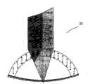
图8显示本发明的附着透镜,其具有以相对于中心轴30度定向的可极化键;Figure 8 shows an attached lens of the present invention having polarizable keys oriented at 30 degrees relative to the central axis;
图9显示本发明示例性材料的化学结构;Figure 9 shows the chemical structure of exemplary materials of the present invention;
图10显示本发明示例性材料的化学结构;Figure 10 shows the chemical structures of exemplary materials of the invention;
图11显示本发明示例性材料的化学结构;Figure 11 shows the chemical structures of exemplary materials of the invention;
图12显示本发明示例性材料的化学结构;Figure 12 shows the chemical structures of exemplary materials of the invention;
图13显示本发明方法的示例性流程框图;Fig. 13 shows an exemplary block flow diagram of the method of the present invention;
图14显示本发明方法的示例性流程框图;和Figure 14 shows an exemplary block flow diagram of the method of the present invention; and
图15显示同时治疗中央凹近视和由光在周边视网膜后方聚焦引起的近视的方法的示例性流程框图。15 shows an exemplary block flow diagram of a method of simultaneously treating foveal myopia and myopia caused by focusing light behind the peripheral retina.
发明详述Detailed description of the invention
以下描述不打算以任何方式限制本发明的范围、适用性或构造,而是为了方便地说明实施本发明的各实施方式。在不背离本发明范围的情况下明显可在这些实施方式所述元件的功能和设置以及材料的组成方面作出各种改变。因此,此处提供的详细描述仅用于说明的目的而非限制的目的。The following description is not intended to limit the scope, applicability, or configuration of the invention in any way, but is for convenience of illustration of various embodiments for practicing the invention. It will be apparent that various changes may be made in the function and arrangement of elements and the composition of materials described in these embodiments without departing from the scope of the invention. Therefore, the detailed description provided herein is for the purpose of illustration only and not of limitation.
根据所述,提供近视控制系统。近视控制系统包括设置为引起所有或一部分进入眼的离轴光线在周边视网膜上或前方聚焦、进入眼的在轴光线在中央凹上聚焦的任何装置或设备。According to that, a myopia control system is provided. Myopia control systems include any device or device configured to cause all or a portion of off-axis rays entering the eye to focus on or in front of the peripheral retina and on-axis rays entering the eye to focus on the fovea.
在一个示例性实施方式中,本发明是使所有或一部分进入眼的离轴光的折射角变陡从而使离轴光线在视网膜上或前部聚焦的装置或系统。例如,本发明的装置或系统可设置为对进入眼的离轴光产生双折射效应而不影响在轴光线的焦点。在这样的实施方式中,所述在轴光线不被所述透镜的双折射特征折射,但可基于其几何构造和非双折射折射率发生所需折射。In one exemplary embodiment, the invention is a device or system that steepens the refraction angle of all or a portion of off-axis light entering the eye so that the off-axis light is focused on or in front of the retina. For example, a device or system of the invention may be configured to produce a birefringent effect on off-axis light entering the eye without affecting the focus of the on-axis light. In such embodiments, the on-axis rays are not refracted by the birefringent features of the lens, but may be refracted as desired based on their geometry and non-birefringent index of refraction.
双折射是将透射光分解为两束光,产生两个焦点,也称为双重折射。双折射效应是具有规则模式取向的可极化分子键的介质中的分子组成导致折射介质中光迟滞的各向异性的体现。在光穿过具有组织化模式分子键的材料传播时,取向平行于所述分子键的光线的迟滞不同于以其它方向取向光线,从而产生两个焦点,各具有约一半的入射光强度。Birefringence is the splitting of transmitted light into two beams, producing two focal points, also known as double refraction. The birefringence effect is a manifestation of the anisotropy in which the molecular composition in a medium of polarizable molecular bonds with regular pattern orientation leads to optical retardation in a refractive medium. As light propagates through a material with organized pattern molecular bonds, rays oriented parallel to the molecular bonds are retarded differently than rays oriented in other directions, creating two focal points, each with about half the intensity of the incident light.
双折射已用于光学领域以产生双焦点效应。例如,Fiala的题为“多焦点双折射透镜系统”(“Multifocal Birefringent Lens System”)(“Fiala”)的美国专利第5,142,411号公开了一种透镜系统,其包括大的单焦点透镜部分和小的双折射透镜部分,以产生“双焦点”效应(第22列,第1-10行)。根据Fiala所述,该构造在单焦点透镜部分产生垂直极化光能够形成远视力,在双折射透镜部分产生水平极化光用于形成近视力(第22列,第40-45行)。该构造允许使用者在两个图像中选择(一个近焦,一个远焦)。Birefringence has been used in optics to create a bifocal effect. For example, U.S. Patent No. 5,142,411 to Fiala, entitled "Multifocal Birefringent Lens System" ("Fiala"), discloses a lens system that includes a large monofocal lens portion and a small part of the birefringent lens to create a "bifocal" effect (
在一个示例性实施方式中,本发明包括具有取向平行或基本平行于眼中心轴的可极化键以对离轴光线产生双折射效应的附着透镜、眼镜或其它视力矫正装置。例如,图3显示附着透镜20,其包含具有基本平行于中心轴22的可极化键25的折射介质。如图4所示,该键取向引起约一半离轴光线25(平行于可极化键传播的光线)比另一半离轴光线25(正交于可极化键传播的光线)迟滞更多,从而产生两个焦点。可从相对于透镜中心轴的所有入射角观察到该双折射效应。In one exemplary embodiment, the present invention includes an attached lens, eyeglass or other vision correcting device having polarizable bonds oriented parallel or substantially parallel to the central axis of the eye to produce a birefringent effect on off-axis light rays. For example, FIG. 3 shows an attached
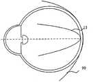
在该示例性实施方式中,在轴光线将穿过所述透镜不发生改变。如图5所示,穿过附着透镜20传播的在轴光线27不会发生迟滞,因为它们不具有取向平行于透镜中可极化键的电场矢量。图6显示由键取向基本平行于透镜中心轴的双折射附着透镜(矫正图2所示的平坦化的聚焦区,其中在非双折射矫正方法的作用下,所有的周边光线均在视网膜后方聚焦)产生的聚焦区13和99。如图所示,双折射透镜使约一半离轴光线折射入具有陡化曲率的第一聚焦区13,使约一半离轴光线折射入视网膜后方的第二聚焦区99。In this exemplary embodiment, the axial rays will pass through the lens unchanged. As shown in Figure 5, on-
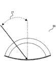
如图7所示,离轴光线的迟滞程度取决于相对于接触透镜20的离轴光11中心轴的入射角27。所述入射角越大,所述光越向内部聚焦。As shown in FIG. 7 , the degree of retardation of the off-axis light depends on the angle of
在一个示例性实施方式中,本发明的附着透镜可包含具有以相对于中心轴的0-90度之间任何入射角定向的可极化键的折射介质,从而将离轴和在轴光线的焦点调整到更朝向视网膜内部,以产生所需聚焦区。例如,图8的实施方式显示具有以相对于中心轴30度定向的可极化键25的附着透镜20。由于非轴取向会开始对在轴光线产生一些影响,会出现轻微的双焦点效应。虽然大的双焦点效应可能是不利的,但可以容许一定程度的双焦点效应。In one exemplary embodiment, an attached lens of the present invention may comprise a refractive medium having a polarizable bond oriented at any angle of incidence between 0-90 degrees relative to the central axis, such that the off-axis and on-axis rays The focal point is adjusted further inwards of the retina to produce the desired focal zone. For example, the embodiment of FIG. 8 shows an attached
在一个示例性实施方式中,本发明的双折射附着透镜显示两种不同的折射率,二者通常相差约不到0.2。然而,应理解,双折射附着透镜可包括相差任何所需距离的折射率,均落入本发明的范围内。In an exemplary embodiment, the birefringent attachment lens of the present invention exhibits two different indices of refraction, typically differing by less than about 0.2. It should be understood, however, that a birefringent attachment lens may include refractive indices that differ by any desired distance and remain within the scope of the present invention.
本发明的实施方式可与任何附着透镜几何、单焦点或多焦点折射光学设计,如球形、非球形、环形、圆柱形和/或任何衍射光学设计联用。此外,可采用适合产生具有所需矫正特征的附着透镜的任何已知或此后设计的技术制造本发明附着透镜。例如,可车削(lathe cut)、模制(molded)或旋切(spin-cut)透镜。Embodiments of the present invention may be used with any attachment lens geometry, monofocal or multifocal refractive optical design, such as spherical, aspherical, toroidal, cylindrical, and/or any diffractive optical design. In addition, any known or hereafter devised technique suitable for producing an attached lens having the desired corrective characteristics can be used to manufacture the attachment lens of the present invention. For example, lenses may be lathe cut, molded or spin-cut.
在一个示例性实施方式中,近视控制系统包括具有双折射材料的视力矫正装置,如眼镜或附着透镜。本发明的双折射材料可以是具有可极化键的任何材料,该可极化键主要定向在一个方向上而放弃其它两个正交方向以产生双折射效应。在一个示例性实施方式中,所述材料可以是多层复合材料。In one exemplary embodiment, a myopia control system includes a vision correcting device, such as eyeglasses or an attached lens, having a birefringent material. The birefringent material of the present invention may be any material having polarizable bonds oriented predominantly in one direction and forgoing the other two orthogonal directions to produce the birefringent effect. In an exemplary embodiment, the material may be a multi-layer composite material.
材料的双折射性质主要由材料的分子组分、波长和温度决定。在可见光区中,寻常折射率(no)在1.5-1.57范围内;no随波长增大而减小,随温度上升而略有增大,在转变温度附近发生显著变化,对分子取代基的依赖性低。非常折射率(ne)强烈依赖于取代基,在可见光区中1.5-1.9范围内变化,取决于共轭水平;ne随波长增大而减小,随温度上升而逐渐减小,在相变附近的温度范围内急剧减小。The birefringence properties of a material are mainly determined by the molecular composition of the material, wavelength and temperature. In the visible light region, the ordinary refractive index (no ) is in the range of 1.5-1.57; no decreases with the increase of wavelength, slightly increases with the increase of temperature, and changes significantly near the transition temperature. low dependency. The extraordinary refractive index (ne ) is strongly dependent on the substituent and varies in the range of 1.5-1.9 in the visible region, depending on the level of conjugation;ne decreases with increasing wavelength and gradually decreases with increasing temperature. decreases sharply in the temperature range around the change.
双折射在晶体无机材料和某些有机材料中均是已知的,这两类材料均能以平行方式表现相似的可极化键取向。本领域技术人员应理解,双折射可能天然存在于材料中(称为“形状双折射”),或可通过对各向同性材料施加机械应力(拉伸)、将各向同性材料置于强电磁场中、自组装型技术(self-assembling type technique)(这些技术称为“诱导双折射”)或任何其它合适的方法诱导双折射。Birefringence is known both in crystalline inorganic materials and in some organic materials, both of which exhibit similar polarizable bond orientations in a parallel fashion. Those skilled in the art will appreciate that birefringence may occur naturally in the material (termed "shape birefringence"), or may be achieved by applying mechanical stress (stretching) to an isotropic material, exposing an isotropic material to a strong electromagnetic field Birefringence can be induced by, self-assembling type technique (these techniques are called "induced birefringence") or any other suitable method.
可通过单一方式按一定拉伸比(draw ratio)进行拉伸在聚合物材料中诱导双折射,假定其它所有参数保持恒定。诱导双折射还依赖于许多其它因素,如拉伸温度、拉伸速度和退火条件等。Birefringence can be induced in polymeric materials by stretching at a certain draw ratio in a single way, assuming all other parameters are held constant. Induced birefringence also depends on many other factors, such as stretching temperature, stretching speed, and annealing conditions.
具有合适诱导双折射性质的聚合物材料包括但不限于聚对苯二甲酸乙二酯、聚碳酸酯、聚砜、聚醚砜、聚苯乙烯、聚酯碳酸酯、选自聚酰胺、聚酯、聚(酰胺-酰亚胺)或聚(酯-酰亚胺)的刚性棒状聚合物以及其中供体和受体取代基诱导大分子偶极矩和增强可极化性各向异性的聚合物。Polymeric materials with suitable induced birefringence properties include, but are not limited to, polyethylene terephthalate, polycarbonate, polysulfone, polyethersulfone, polystyrene, polyester carbonate, selected from polyamide, polyester , rigid rod-like polymers of poly(amide-imide) or poly(ester-imide), and polymers in which donor and acceptor substituents induce macromolecular dipole moments and enhance polarizability anisotropy .
根据一个示例性实施方式,具有合适诱导双折射性质的聚合物包括掺杂(客体-主体)系统、侧链聚合物、主链聚合物(包括刚性棒状聚合物)和交联材料。图9提供这些系统化学结构的例子和的发色团化学结构的例子。According to an exemplary embodiment, polymers with suitable induced birefringence properties include doped (guest-host) systems, side chain polymers, backbone polymers (including rigid rod polymers), and crosslinked materials. Figure 9 provides examples of chemical structures of these systems and examples of chromophore chemical structures.
在掺杂(客体-主体)材料系统中,可通过向聚合物基质中掺入双折射发色团来诱导双折射。适合用于该示例性实施方式的各种双折射掺杂剂和聚合物材料均可从市场上购得。In doped (guest-host) material systems, birefringence can be induced by incorporating birefringent chromophores into the polymer matrix. Various birefringent dopants and polymeric materials suitable for use in this exemplary embodiment are commercially available.
例如,可使用液晶(LC)掺杂剂如二甲氨基硝基二苯乙烯(DANS)和如图10所示的具有硝基和氰基作为电子接受基团的其它相关结构。For example, liquid crystal (LC) dopants such as dimethylaminostilbene (DANS) and other related structures having nitro and cyano groups as electron-accepting groups as shown in FIG. 10 can be used.
其它LC掺杂剂也适合用于本发明的双折射附着透镜。例如,可使用分散在UV固化甲基丙烯酸酯聚合物中的氰基苯基向列型LC产生的复合材料,膜厚度约为5μ时室温测定所述复合材料的透光率大于80%,双折射率为0.18-0.24。Other LC dopants are also suitable for use in the birefringent attachment lenses of the present invention. For example, a composite material produced by cyanophenyl nematic LC dispersed in a UV-curable methacrylate polymer can be used, and the light transmittance of the composite material is greater than 80% measured at room temperature when the film thickness is about 5μ. The refractive index is 0.18-0.24.
此外,含向列型LC和铁电LC的复合材料是适合用于本发明的材料,所述向列型LC在27∶2C下、400-800nm光谱范围内的双折射率在0∶16-0.24范围内。也可使用一种基于环氧物的系统(E7,一种环氧树脂基质EP0305中的向列型LC),其显示的透光率在50-80%范围内,35摄氏度下的双折射率约为0.2。In addition, a composite material containing a nematic LC and a ferroelectric LC having a birefringence in the range of 0:16- 0.24 range. An epoxy-based system (E7, a nematic LC in an epoxy resin matrix EP0305) is also available which exhibits transmittance in the range of 50-80%, birefringence at 35°C About 0.2.
也可通过例如掺入纳米尺寸的无机双折射晶体或低分子量棒状掺杂剂(染料、多烯、液晶),然后进行定向,来增强光学聚合物的双折射性质。该定向也可包括分子排列和电磁场对准的朗缪尔-布罗杰特(Langmuir-Blodgett)或自组装型技术。The birefringent properties of optical polymers can also be enhanced by eg incorporation of nano-sized inorganic birefringent crystals or low molecular weight rod-like dopants (dyes, polyenes, liquid crystals) followed by orientation. The orientation may also include Langmuir-Blodgett or self-assembly type techniques of molecular alignment and electromagnetic field alignment.
在侧链聚合物材料中,可通过将双折射发色团(如液晶基团、光致变色基团)连接到聚合物链上诱导双折射。这些材料增强发色团密度和热稳定性。这些材料的主要构建单元是聚合物主链、悬垂的双折射侧基和连接这两种组分的间隔基。In side-chain polymer materials, birefringence can be induced by attaching birefringent chromophores (eg mesogenic groups, photochromic groups) to the polymer chains. These materials enhance chromophore density and thermal stability. The main building blocks of these materials are a polymer backbone, pendant birefringent pendant groups, and a spacer linking the two components.
可通过改变所述三种构建单元中的至少一种来改变这类双折射聚合物的性质。所述聚合物的实际双折射效应主要取决于双折射侧基,然而,主链或间隔基的刚度影响双折射基的旋转自由度,因此在例如施加电磁场后会影响可达到的最大取向。The properties of such birefringent polymers can be altered by changing at least one of the three building blocks. The actual birefringent effect of the polymer depends mainly on the birefringent side groups, however, the stiffness of the main chain or spacer affects the rotational freedom of the birefringent groups and thus the maximum orientation achievable after e.g. application of an electromagnetic field.
在侧链聚合物中,如图11所示,双折射聚合物的热性质和机械性质取决于所有三种组分。主链对聚合物的玻璃化转变温度(Tg)特别重要。含硅氧烷结构的主链的Tg值为7℃-40℃,含丙烯酸酯结构的主链显示约80℃的Tg,含聚酰亚胺结构的主链具有最高达400℃的Tg。间隔基和侧基也会影响Tg值,通常柔性的长间隔基可降低Tg。In side chain polymers, as shown in Figure 11, the thermal and mechanical properties of birefringent polymers depend on all three components. The backbone is of particular importance to the glass transition temperature (Tg) of the polymer. The Tg value of the main chain containing the siloxane structure is 7°C-40°C, the main chain containing the acrylate structure shows a Tg of about 80°C, and the main chain containing the polyimide structure has a Tg up to 400°C. Spacers and side groups also affect Tg values, usually flexible long spacers can reduce Tg.
光学性质取决于所述三种组分的特定组合。由于可极化性和光学各向异性值高,侧基如4-甲氧基-4’-硝基二苯乙烯(MONS)或4-二甲氨基-4’-硝基二苯乙烯(DANS)倾向于主导光学性质。在可极化性/光学各向异性低的基团中,主链和间隔基对光学性质起主要作用。使用侧链聚合物的一个主要优点涉及其可加工性。Optical properties depend on the specific combination of the three components. Due to the high polarizability and optical anisotropy values, side groups such as 4-methoxy-4'-nitrostilbene (MONS) or 4-dimethylamino-4'-nitrostilbene (DANS ) tend to dominate the optical properties. In groups with low polarizability/optical anisotropy, the main chain and spacer play a major role in optical properties. A major advantage of using side chain polymers relates to their processability.
文献中描述的大多数侧链聚合物均打算用于倍频应用(frequency doubling application)。在这样的应用中,将所述聚合物加工为薄膜,在Tg附近的温度下用电场使其发生“极化”。在活性位点极化后,对所述聚合物进行骤冷处理以保留具有双折射特性的有序结构。以该方式加工的材料的主要问题是其长期热稳定性。由于所述基团经聚合物链的运动而松弛,所述分子随时间放松并失去其取向。显示Tg值和聚合物交联高的材料是可能的解决方法以增强所述材料双折射性质的稳定性。Most of the side chain polymers described in the literature are intended for frequency doubling applications. In such applications, the polymer is processed into a thin film, which is "polarized" with an electric field at a temperature around Tg. After the active sites are polarized, the polymer is quenched to preserve the ordered structure with birefringent properties. A major problem with materials processed in this way is their long-term thermal stability. The molecule relaxes and loses its orientation over time as the groups relax through movement of the polymer chain. Materials showing high Tg values and polymer crosslinking are possible solutions to enhance the stability of the birefringent properties of the materials.
由于聚合物链具有非对称性,通过拉伸不难将包括刚性棒状聚合物在内的主链聚合物定向为双折射制品。图12提供主链聚合物化学结构的例子。为更显著的效应,可通过向聚合物主链中掺入发色团达到更高的各向异性发色团密度。显示双折射的刚性棒状聚合物还提供了时间-温度稳定性方面的优点。Due to the asymmetric nature of the polymer chains, it is not difficult to orient backbone polymers, including rigid rod polymers, into birefringent articles by stretching. Figure 12 provides examples of backbone polymer chemical structures. For a more pronounced effect, higher anisotropic chromophore densities can be achieved by incorporating chromophores into the polymer backbone. Rigid rod polymers exhibiting birefringence also offer advantages in terms of time-temperature stability.
在一个实施方式中,本发明的聚合物材料可包括以上列出的一种或多种聚合物材料和具有所需性质的一种或多种其它组分的混合物,如增大氧透射、增强机械性质和/或其它所需光学性质的材料。In one embodiment, the polymeric material of the present invention may comprise a mixture of one or more of the polymeric materials listed above and one or more other components having desired properties, such as increased oxygen transmission, enhanced Materials with mechanical properties and/or other desired optical properties.
根据另一个示例性实施方式,本发明的系统设置为同时治疗和/或预防中央凹近视和由刺激周边视网膜引起的近视。例如,本发明的附着透镜可设置为(1)采用角膜曲率矫正术整形角膜(即使其变平);和(2)包含具有合适定向的可极化键的双折射材料,以预防由周边视网膜引起的近视。在这样的实施方式中,所述可极化键可定向为平行或基本平行于眼中心轴或具有任何其它合适的取向。应理解,同时治疗中央凹近视和由周边视网膜引起的近视的任何系统均可用于本发明。According to another exemplary embodiment, the system of the present invention is configured to simultaneously treat and/or prevent foveal myopia and myopia caused by stimulation of the peripheral retina. For example, the attachment lenses of the present invention can be configured to (1) reshape (i.e. flatten) the cornea using orthokeratology; and (2) contain birefringent material with properly oriented polarizable bonds to prevent damage to the peripheral retina. caused myopia. In such embodiments, the polarizable bonds may be oriented parallel or substantially parallel to the central axis of the eye or have any other suitable orientation. It should be understood that any system that treats both foveal myopia and myopia caused by the peripheral retina may be used in the present invention.
在本发明的一个示例性实施方式中,提供本发明所述的治疗和预防视敏度损失的方法。本发明的方法是提供光学矫正装置的任何方法,该装置能够引起离轴光线在周边视网膜前方聚焦而基本不改变在轴光线焦点。In an exemplary embodiment of the present invention, there is provided a method of treating and preventing loss of visual acuity described herein. The method of the present invention is any method that provides an optical correction device capable of causing off-axis rays to be focused in front of the peripheral retina without substantially changing the on-axis ray focus.
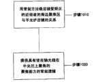
如图13所示,本发明的示例性方法包括步骤1010:用常规方法确定接受矫正的近视者的周边聚焦区与平光护目镜的关系;和步骤1020:提供具有使在轴光线在中央凹上聚焦的聚焦能力的常规透镜。As shown in FIG. 13, the exemplary method of the present invention includes step 1010: determining the relationship between the peripheral focal area and the plano goggle of a myopic person receiving correction using conventional methods; Focusing power of conventional lenses.
如图14所示,治疗视敏度缺陷的方法的一个示例性实施方式包括步骤1110:测定视网膜的相对位置和曲率;步骤1120:测定进入患者眼的光线聚焦区的相对位置和曲率;步骤1130:确定所述聚焦区是否比周边视网膜更平坦且位于其后方;步骤1140:选择具有适合诱导双折射效应的聚合键取向的材料,从而使离轴光线在周边视网膜上或前方至少一处聚焦;和步骤1150:提供具有使在轴光线在中央凹上聚焦的聚焦能力和轴向双折射特征的常规透镜,从而将离轴光线的一部分光相比不存在取向双折射的情况更多地移到周边视网膜前方的焦点。本领域技术人员应理解,可采用任何已知或此后设计的技术测定视网膜和聚焦区的曲率。As shown in Figure 14, an exemplary embodiment of the method for the treatment of visual acuity defect comprises step 1110: measure the relative position and curvature of retina; Step 1120: measure the relative position and curvature of the focal region of light entering patient's eye; Step 1130 : determining whether the focal zone is flatter than and behind the peripheral retina; step 1140 : selecting a material with a polymer bond orientation suitable for inducing a birefringence effect so that off-axis rays are focused at least one place on or in front of the peripheral retina; and STEP 1150: providing a conventional lens with focusing power and axial birefringence characteristics to focus on-axis rays on the fovea, thereby shifting a portion of the off-axis rays to the The focal point in front of the peripheral retina. Those skilled in the art will appreciate that any known or hereafter devised technique may be used to determine the curvature of the retina and focal zone.
在尚未对患者实施治疗中央凹近视的常规方法(如角膜曲率矫正术、LASIK等)的情况中,参照图15,本发明的一个示例性实施方式包括步骤1210:测定患者视网膜的相对位置和曲率;步骤1220:测定患者聚焦区的相对位置和曲率;步骤1230:确定患者聚焦区的曲率比其视网膜的曲率更平坦;步骤1240:确定具有适合使进入眼周边角膜的光线的聚焦区变陡的双折射性质的材料的聚合键取向,从而使所述光线在周边视网膜上或前方至少一处聚焦;步骤1250:进行中央凹近视治疗。这可能会采用双折射性质和充分在轴能力的形式来治疗中央凹近视;和步骤1260:向患者提供具有最佳键取向的双折射附着透镜。中央凹近视治疗可包括适合引起进入眼的光在中央凹上聚焦的任何已知或此后设计的技术,如角膜曲率矫正术和角膜折射外科手术。In cases where conventional methods of treating foveal myopia (such as orthokeratology, LASIK, etc.) have not been performed on the patient, referring to FIG. 15 , an exemplary embodiment of the present invention includes step 1210 of determining the relative position and curvature of the patient's retina ; Step 1220: determine the relative position and curvature of the patient's focal zone; Step 1230: determine that the curvature of the patient's focal zone is flatter than the curvature of its retina; The polymer bonds of the birefringent material are oriented so that the light rays are focused at least one place on or in front of the peripheral retina; step 1250: perform foveal myopia treatment. This may take the form of birefringent properties and sufficient on-axis capabilities to treat foveal myopia; and Step 1260: Providing the patient with a birefringent attachment lens with optimal key orientation. Foveal myopia treatment may include any known or hereafter devised technique suitable for causing light entering the eye to focus on the fovea, such as orthokeratology and corneal refractive surgery.
根据另一个示例性实施方式,本发明的方法可包括制造和/或提供同时具有角膜曲率矫正学性质和双折射能力的附着透镜。According to another exemplary embodiment, the method of the present invention may comprise manufacturing and/or providing an attachment lens having both orthokeratology properties and birefringence capabilities.
对本文所述的本发明作出各种改变、变动和修改对本领域技术人员是显而易见的。例如,以上引用的步骤可互换和/或省略,仍落入本发明的范围内。Various changes, modifications and modifications to the invention described herein will be apparent to those skilled in the art. For example, the steps cited above may be interchanged and/or omitted and still fall within the scope of the present invention.
Claims (21)
Translated fromChineseApplications Claiming Priority (3)
| Application Number | Priority Date | Filing Date | Title |
|---|---|---|---|
| US12/110,999 | 2008-04-28 | ||
| US12/110,999US7905595B2 (en) | 2008-04-28 | 2008-04-28 | System and method to treat and prevent loss of visual acuity |
| PCT/US2009/041069WO2009134632A1 (en) | 2008-04-28 | 2009-04-20 | System and method to treat and prevent loss of visual acuity |
Publications (2)
| Publication Number | Publication Date |
|---|---|
| CN102046068Atrue CN102046068A (en) | 2011-05-04 |
| CN102046068B CN102046068B (en) | 2014-06-25 |
Family
ID=41214646
Family Applications (1)
| Application Number | Title | Priority Date | Filing Date |
|---|---|---|---|
| CN200980120939.9AActiveCN102046068B (en) | 2008-04-28 | 2009-04-20 | Systems and methods for treating and preventing loss of visual acuity |
Country Status (4)
| Country | Link |
|---|---|
| US (1) | US7905595B2 (en) |
| EP (1) | EP2276394B1 (en) |
| CN (1) | CN102046068B (en) |
| WO (1) | WO2009134632A1 (en) |
Cited By (2)
| Publication number | Priority date | Publication date | Assignee | Title |
|---|---|---|---|---|
| CN105411521A (en)* | 2015-12-07 | 2016-03-23 | 温州医科大学眼视光器械有限公司 | Crystalline lens image detection device |
| CN111095084A (en)* | 2018-03-01 | 2020-05-01 | 依视路国际公司 | Lens element |
Families Citing this family (13)
| Publication number | Priority date | Publication date | Assignee | Title |
|---|---|---|---|---|
| US8246167B2 (en)* | 2009-12-17 | 2012-08-21 | Crt Technology, Inc. | Systems and methods for the regulation of emerging myopia |
| TWI588560B (en) | 2012-04-05 | 2017-06-21 | 布萊恩荷登視覺協會 | Lens, device, method and system for refractive error |
| KR101374292B1 (en) | 2012-07-13 | 2014-03-17 | 주식회사 루트로닉 | Apparatus for treating ocular and method for radiating treatment beam thereof |
| US9201250B2 (en) | 2012-10-17 | 2015-12-01 | Brien Holden Vision Institute | Lenses, devices, methods and systems for refractive error |
| CA2887655C (en) | 2012-10-17 | 2021-11-02 | Brien Holden Vision Institute | Lenses, devices, methods and systems for refractive error |
| JP5689208B1 (en)* | 2013-12-09 | 2015-03-25 | 株式会社ユニバーサルビュー | Contact lens combination series and selection method. |
| WO2015087436A1 (en)* | 2013-12-09 | 2015-06-18 | 株式会社ユニバーサルビュー | Contact lens and method for selecting same |
| BR112016017990B1 (en) | 2014-02-04 | 2022-06-14 | Crt Technology, Inc | MULTIFUNCTIONAL CONTACT LENS |
| SG10201400920RA (en)* | 2014-03-24 | 2015-10-29 | Menicon Singapore Pte Ltd | Apparatus and methods for controlling axial growth with an ocular lens |
| CA2946693A1 (en) | 2014-04-16 | 2015-10-22 | David E. Roberts | Methods and apparatus for human vision correction using diffractive waveplate lenses |
| US10268050B2 (en) | 2015-11-06 | 2019-04-23 | Hoya Lens Thailand Ltd. | Spectacle lens |
| US10859857B2 (en) | 2016-03-22 | 2020-12-08 | Johnson & Johnson Vision Care, Inc. | Pulsed plus lens designs for myopia control, enhanced depth of focus and presbyopia correction |
| EP4242735A3 (en)* | 2018-04-26 | 2023-11-22 | Essilor International | Lens element |
Citations (6)
| Publication number | Priority date | Publication date | Assignee | Title |
|---|---|---|---|---|
| US5073021A (en)* | 1989-03-17 | 1991-12-17 | Environmental Research Institute Of Michigan | Bifocal ophthalmic lens constructed from birefringent material |
| US5142411A (en)* | 1987-09-24 | 1992-08-25 | Werner J. Fiala | Multifocal birefringent lens system |
| US5963297A (en)* | 1997-06-27 | 1999-10-05 | Reim; Thomas Russell | Orthokeratology contact lens and method therefor |
| EP1394575A1 (en)* | 2001-06-04 | 2004-03-03 | Ir Gvon Khan | Optical device |
| CN1909860A (en)* | 2003-11-19 | 2007-02-07 | 视力Crc有限公司 | Method and apparatus for varying relative field curvature and peripheral off-axis focus position |
| US20070296916A1 (en)* | 2006-06-08 | 2007-12-27 | Holden Brien A | Means for controlling the progression of myopia |
Family Cites Families (12)
| Publication number | Priority date | Publication date | Assignee | Title |
|---|---|---|---|---|
| US1918848A (en)* | 1929-04-26 | 1933-07-18 | Norwich Res Inc | Polarizing refracting bodies |
| US1963496A (en)* | 1933-01-16 | 1934-06-19 | Edwin H Land | Light valve |
| US2005426A (en)* | 1933-11-03 | 1935-06-18 | Edwin H Land | Polarizing vizor or sunshade |
| US2123901A (en)* | 1936-04-03 | 1938-07-19 | Sheet Polarizer Company Inc | Light polarizing material |
| US5410375A (en)* | 1990-03-15 | 1995-04-25 | Fiala; Werner J. | Multifocal birefrigent lens with adjusted birefringence |
| ATA95693A (en)* | 1993-05-14 | 1997-11-15 | Bifocon Optics Forsch & Entw | LENS |
| US5629055A (en)* | 1994-02-14 | 1997-05-13 | Pulp And Paper Research Institute Of Canada | Solidified liquid crystals of cellulose with optically variable properties |
| US6217171B1 (en)* | 1998-05-26 | 2001-04-17 | Novartis Ag | Composite ophthamic lens |
| US6250757B1 (en)* | 1999-12-15 | 2001-06-26 | Johnson & Johnson Vision Products, Inc. | Hybrid refractive birefringent multifocal ophthalmic lenses |
| US7152975B2 (en) | 2000-11-10 | 2006-12-26 | Cooper Vision, Inc. | Junctionless ophthalmic lenses and methods for making same |
| US6896368B2 (en)* | 2003-05-07 | 2005-05-24 | Thomas K. Baugh | Multifocal soft contact lens with horizontally decentered lenslet and indicator marking |
| JP3847744B2 (en)* | 2003-11-04 | 2006-11-22 | オリンパス株式会社 | Insertion support system |
- 2008
- 2008-04-28USUS12/110,999patent/US7905595B2/enactiveActive
- 2009
- 2009-04-20EPEP09739434.0Apatent/EP2276394B1/enactiveActive
- 2009-04-20WOPCT/US2009/041069patent/WO2009134632A1/enactiveApplication Filing
- 2009-04-20CNCN200980120939.9Apatent/CN102046068B/enactiveActive
Patent Citations (6)
| Publication number | Priority date | Publication date | Assignee | Title |
|---|---|---|---|---|
| US5142411A (en)* | 1987-09-24 | 1992-08-25 | Werner J. Fiala | Multifocal birefringent lens system |
| US5073021A (en)* | 1989-03-17 | 1991-12-17 | Environmental Research Institute Of Michigan | Bifocal ophthalmic lens constructed from birefringent material |
| US5963297A (en)* | 1997-06-27 | 1999-10-05 | Reim; Thomas Russell | Orthokeratology contact lens and method therefor |
| EP1394575A1 (en)* | 2001-06-04 | 2004-03-03 | Ir Gvon Khan | Optical device |
| CN1909860A (en)* | 2003-11-19 | 2007-02-07 | 视力Crc有限公司 | Method and apparatus for varying relative field curvature and peripheral off-axis focus position |
| US20070296916A1 (en)* | 2006-06-08 | 2007-12-27 | Holden Brien A | Means for controlling the progression of myopia |
Cited By (2)
| Publication number | Priority date | Publication date | Assignee | Title |
|---|---|---|---|---|
| CN105411521A (en)* | 2015-12-07 | 2016-03-23 | 温州医科大学眼视光器械有限公司 | Crystalline lens image detection device |
| CN111095084A (en)* | 2018-03-01 | 2020-05-01 | 依视路国际公司 | Lens element |
Also Published As
| Publication number | Publication date |
|---|---|
| CN102046068B (en) | 2014-06-25 |
| EP2276394A1 (en) | 2011-01-26 |
| EP2276394A4 (en) | 2011-08-17 |
| WO2009134632A1 (en) | 2009-11-05 |
| EP2276394B1 (en) | 2013-07-17 |
| US7905595B2 (en) | 2011-03-15 |
| US20090268154A1 (en) | 2009-10-29 |
Similar Documents
| Publication | Publication Date | Title |
|---|---|---|
| CN102046068A (en) | Systems and methods for treating and preventing loss of visual acuity | |
| US11971615B2 (en) | Electro-switchable spectacles for myopia treatment | |
| AU2014221205B2 (en) | Method and apparatus for ophthalmic devices including shaped liquid crystal polymer networked regions of liquid crystal | |
| AU2014221201B2 (en) | Method and apparatus for ophthalmic devices comprising dielectrics and liquid crystal polymer networks | |
| AU2014227463B2 (en) | Method and apparatus for ophthalmic devices including gradient-indexed liquid crystal layers and shaped dielectric layers | |
| JP2023528307A (en) | A patch-on device for treating progressive refractive error using peripheral defocusing | |
| JP6433736B2 (en) | Variable optical ophthalmic device including a liquid crystal element | |
| JP7496142B2 (en) | Electrically adjustable vision aid for the treatment of myopia | |
| TW202200098A (en) | Stick on devices using peripheral defocus to treat progressive refractive error | |
| US20070052886A1 (en) | Contact lenses with selective spectral blocking and method of fabrication thereof | |
| TW202522090A (en) | Spectacle lenses with auxiliary optical elements | |
| TW201138744A (en) | Adjustable intraocular lens system | |
| JP2015072469A (en) | Variable optic ophthalmic device including shaped liquid crystal elements with nano-scaled droplets of liquid crystal | |
| JP2018527596A (en) | Rewritable lens and manufacturing method | |
| AU2004243926A1 (en) | Methods and apparatuses for controlling optical aberrations to alter modulation transfer functions | |
| TW200914911A (en) | Ophthalmic lenses for prevention of myopia progression | |
| RU2677585C2 (en) | Methods of forming optical ophthalmic devices with a variable optical part including formed liquid crystalline elements | |
| WO2014198027A1 (en) | Ametropia treatment spectacles | |
| US6733122B1 (en) | Optical system, in particular intraocular lens, contact lens | |
| JP2020529262A (en) | Birefringence intraocular lens | |
| WO2006092088A1 (en) | A compound spectacle | |
| US20200249501A1 (en) | Wavefront engineered lenses for correction of presbyopia and astigmatism and nanoparticle-doped liquid crystal structures for continuously tunable phase modulation and adaptive lens | |
| CN219456656U (en) | An adjustable focus and dimming device for alleviating eye fatigue | |
| HK1190202A (en) | Inversion marking for contact lenses |
Legal Events
| Date | Code | Title | Description |
|---|---|---|---|
| C06 | Publication | ||
| PB01 | Publication | ||
| C10 | Entry into substantive examination | ||
| SE01 | Entry into force of request for substantive examination | ||
| C14 | Grant of patent or utility model | ||
| GR01 | Patent grant |