CN102044896A - Docks and Device Adapters for Docks - Google Patents
Docks and Device Adapters for DocksDownload PDFInfo
- Publication number
- CN102044896A CN102044896ACN2010105403462ACN201010540346ACN102044896ACN 102044896 ACN102044896 ACN 102044896ACN 2010105403462 ACN2010105403462 ACN 2010105403462ACN 201010540346 ACN201010540346 ACN 201010540346ACN 102044896 ACN102044896 ACN 102044896A
- Authority
- CN
- China
- Prior art keywords
- adapter
- docking station
- portable electronic
- contact opening
- housing region
- Prior art date
- Legal status (The legal status is an assumption and is not a legal conclusion. Google has not performed a legal analysis and makes no representation as to the accuracy of the status listed.)
- Pending
Links
Images


Classifications
- G—PHYSICS
- G06—COMPUTING OR CALCULATING; COUNTING
- G06F—ELECTRIC DIGITAL DATA PROCESSING
- G06F1/00—Details not covered by groups G06F3/00 - G06F13/00 and G06F21/00
- G06F1/16—Constructional details or arrangements
- G06F1/1613—Constructional details or arrangements for portable computers
- G06F1/1632—External expansion units, e.g. docking stations
- H—ELECTRICITY
- H02—GENERATION; CONVERSION OR DISTRIBUTION OF ELECTRIC POWER
- H02J—CIRCUIT ARRANGEMENTS OR SYSTEMS FOR SUPPLYING OR DISTRIBUTING ELECTRIC POWER; SYSTEMS FOR STORING ELECTRIC ENERGY
- H02J7/00—Circuit arrangements for charging or depolarising batteries or for supplying loads from batteries
- H—ELECTRICITY
- H01—ELECTRIC ELEMENTS
- H01R—ELECTRICALLY-CONDUCTIVE CONNECTIONS; STRUCTURAL ASSOCIATIONS OF A PLURALITY OF MUTUALLY-INSULATED ELECTRICAL CONNECTING ELEMENTS; COUPLING DEVICES; CURRENT COLLECTORS
- H01R31/00—Coupling parts supported only by co-operation with counterpart
- H01R31/06—Intermediate parts for linking two coupling parts, e.g. adapter
- H—ELECTRICITY
- H04—ELECTRIC COMMUNICATION TECHNIQUE
- H04M—TELEPHONIC COMMUNICATION
- H04M1/00—Substation equipment, e.g. for use by subscribers
- H04M1/02—Constructional features of telephone sets
- H04M1/04—Supports for telephone transmitters or receivers
- H—ELECTRICITY
- H02—GENERATION; CONVERSION OR DISTRIBUTION OF ELECTRIC POWER
- H02J—CIRCUIT ARRANGEMENTS OR SYSTEMS FOR SUPPLYING OR DISTRIBUTING ELECTRIC POWER; SYSTEMS FOR STORING ELECTRIC ENERGY
- H02J2310/00—The network for supplying or distributing electric power characterised by its spatial reach or by the load
- H02J2310/10—The network having a local or delimited stationary reach
- H02J2310/20—The network being internal to a load
- H02J2310/22—The load being a portable electronic device
- H—ELECTRICITY
- H02—GENERATION; CONVERSION OR DISTRIBUTION OF ELECTRIC POWER
- H02J—CIRCUIT ARRANGEMENTS OR SYSTEMS FOR SUPPLYING OR DISTRIBUTING ELECTRIC POWER; SYSTEMS FOR STORING ELECTRIC ENERGY
- H02J7/00—Circuit arrangements for charging or depolarising batteries or for supplying loads from batteries
- H02J7/0042—Circuit arrangements for charging or depolarising batteries or for supplying loads from batteries characterised by the mechanical construction
- H02J7/0044—Circuit arrangements for charging or depolarising batteries or for supplying loads from batteries characterised by the mechanical construction specially adapted for holding portable devices containing batteries
Landscapes
- Engineering & Computer Science (AREA)
- Theoretical Computer Science (AREA)
- Computer Hardware Design (AREA)
- Human Computer Interaction (AREA)
- Physics & Mathematics (AREA)
- General Engineering & Computer Science (AREA)
- General Physics & Mathematics (AREA)
- Signal Processing (AREA)
- Power Engineering (AREA)
- Charge And Discharge Circuits For Batteries Or The Like (AREA)
Abstract
Translated fromChinese
Description
Translated fromChinese相关申请的交叉引用参照CROSS-REFERENCE TO RELATED APPLICATIONS
本申请要求系列号为61/253,318和61/303,308、申请日分别为2009年10月20日和2010年2月10日的相应美国临时申请的优先权。This application claims priority to corresponding US Provisional Applications Serial Nos. 61/253,318 and 61/303,308, filed October 20, 2009, and February 10, 2010, respectively.
技术领域technical field
本发明一般涉及为用于对用于便携电子设备的电池进行充电和/或向便携电子设备导入或导出数据的扩展坞(docking station)。更具体而言,本发明涉及适于直接容纳可充电电池和/或通过其配有或不配有壳套的便携电子设备来容纳可充电电池的扩展坞。本发明还涉及可移除的设备适配器,与扩展底座配合使用以直接容纳可充电电池和/或通过其配有或不配有壳套的便携电子设备来容纳可充电电池。The present invention generally relates to docking stations for charging batteries for portable electronic devices and/or importing or exporting data to and from portable electronic devices. More specifically, the present invention relates to a docking station adapted to accommodate rechargeable batteries directly and/or through a portable electronic device thereof with or without a case. The present invention also relates to a removable device adapter for use with a docking station to receive a rechargeable battery directly and/or through a portable electronic device with or without a case.
背景技术Background technique
各种扩展坞都已被设计为与便携电子设备一起对电池进行充电和/或从便携电子设备中转移数据。典型地,这样的扩展坞可以形成有容纳腔,其适于具有特别的形状和尺寸以容纳便携电子设备的一部分,从而在扩展坞中支撑该便携电子设备。在充电和/或从便携电子设备中转移数据的操作中,在扩展坞的容纳腔中直接容纳含有电池的便携电子设备。Various docking stations have been designed to charge batteries and/or transfer data from portable electronic devices in conjunction with the portable electronic devices. Typically, such a docking station may be formed with a receiving cavity adapted to have a particular shape and size to accommodate a portion of a portable electronic device, thereby supporting the portable electronic device in the docking station. During the operation of charging and/or transferring data from the portable electronic device, the portable electronic device containing the battery is directly accommodated in the receiving chamber of the docking station.
便携电子设备典型地配合可移除壳套而使用,壳套可在日常使用中保护或者装饰便携电子设备。当对这样的便携电子设备进行充电时,使用者经常需要在将便携电子设备放置在扩展坞内进行充电之前将壳套移除。在充电操作完成之后,使用者必须将壳套重新套上便携电子设备以保护和/或装饰该便携电子设备。这样移除、装上的多余操作,每次在将便携电子设备放置在扩展坞内为其充电和/或从便携电子设备中转移数据时,会导致使用者的不便。Portable electronic devices are typically used with removable cases that protect or decorate the portable electronic device during everyday use. When charging such a portable electronic device, the user often needs to remove the case before placing the portable electronic device in the docking station for charging. After the charging operation is completed, the user must put the case back on the portable electronic device to protect and/or decorate the portable electronic device. Such redundant operations of removing and installing will cause inconvenience to the user every time the portable electronic device is placed in the docking station to charge it and/or transfer data from the portable electronic device.
另外,现有的扩展坞均用于特别类型和型号的便携电子设备。当使用各种不同类型或型号的便携电子设备时,需要提供各种不同的扩展坞,这将会引起混乱的桌面放置(desktop arrangement)。Additionally, existing docking stations are designed for specific types and models of portable electronic devices. When using various types or models of portable electronic devices, it is necessary to provide various docking stations, which can cause confusing desktop arrangements.
以下的描述将会提供克服上述不便之处的扩展坞,并简化充电操作和/或从不同便携电子设备中进行数据转移的操作。The following description will provide a docking station that overcomes the above inconveniences and simplifies charging and/or data transfer from different portable electronic devices.
发明内容Contents of the invention
此处公开的实施例总体上涉及为用于便携电子设备的电池充电和/或从便携电子设备中导入或导出数据的扩展坞(docking station)。所述扩展坞适于直接容纳可充电电池和/或通过其配有或不配有壳套的便携电子设备来容纳可充电电池。举例而言,该扩展坞具有容纳区域,可以被设置为容纳并保持便携电子设备。被容纳于扩展坞的便携电子设备可以配有壳套。可选地,当便携电子设备未配有任何壳套时,便携电子设备可以被直接容纳于扩展坞中。扩展坞的容纳区域有接触口,从而在充电过程和/或从便携电子设备中导入或导出数据的数据传输过程中为便携电子设备提供电气接触。Embodiments disclosed herein relate generally to docking stations for charging batteries for portable electronic devices and/or importing or exporting data from portable electronic devices. The docking station is adapted to accommodate rechargeable batteries directly and/or through its portable electronic device with or without a case. For example, the docking station has a receiving area that can be configured to receive and hold a portable electronic device. The portable electronic device housed in the docking station may be provided with a case. Alternatively, when the portable electronic device is not equipped with any case, the portable electronic device can be directly accommodated in the docking station. The receiving area of the docking station has contacts to provide electrical contacts to the portable electronic device during charging and/or data transfer to or from the portable electronic device.
本发明还涉及与扩展坞配合使用的可移除的设备适配器(device adapter),以直接容纳可充电电池和/或通过配有或不配有壳套的便携电子设备来容纳可充电电池。举例来说,在对可充电电池进行充电的过程中和/或在对便携电子设备进行数据传输的操作中,设备适配器可移除地被用于扩展坞中。设备适配器被设置为具有被扩展坞支撑的适配器主体。所述设备适配器还被设置为具有至少一个容纳区域以容纳可充电电池和/或便携电子设备。便携电子设备可以配有或者可以不配有壳套。另外,设备适配器被设置为至少具有一个接触口电气连接位于扩展坞上的接触口,从而在为可充电电池充电过程和/或为便携电子设备转移数据的过程中,为可充电电池和/或便携电子设备提供电气接触。The present invention also relates to a removable device adapter for use with a docking station to accommodate a rechargeable battery directly and/or through a portable electronic device with or without a case. For example, a device adapter is removably used in a docking station during charging of a rechargeable battery and/or during data transfer operations to a portable electronic device. A device adapter is provided having an adapter body supported by a docking station. The device adapter is also configured to have at least one receiving area for receiving a rechargeable battery and/or a portable electronic device. Portable electronic devices may or may not be provided with a case. In addition, the device adapter is configured to have at least one contact port electrically connected to the contact port on the docking station, so that the rechargeable battery and/or Portable electronic devices provide electrical contacts.
所述扩展坞能被用于两种工作位置。在第一工作位置,所述设备适配器可以从扩展坞的容纳区域中被移除,从而便携电子设备可以直接被容纳于扩展坞的容纳区域中。举例而言,便携电子设备可以直接被容纳于扩展坞的容纳区域而没有任何壳套。在这样的工作位置,扩展坞可以被作为类似传统扩展坞而使用。在第二工作位置,扩展坞与设备适配器配合使用,此时可充电电池和/或便携电子设备被容纳于设备适配器的容纳区域。举例而言,配有壳套的便携电子设备可以被容纳于设备适配器的容纳区域,并在为可充电电池和/或便携电子设备在为可充电电池充电过程和/或为便携电子设备转移数据的过程中,一直被保持在该位置上。The docking station can be used in two working positions. In the first working position, the device adapter can be removed from the receiving area of the docking station, so that the portable electronic device can be directly received in the receiving area of the docking station. For example, the portable electronic device can be directly accommodated in the accommodation area of the docking station without any shell. In this working position, the docking station can be used like a conventional docking station. In the second working position, the docking station is used with the device adapter, and the rechargeable battery and/or portable electronic device is received in the receiving area of the device adapter. For example, a portable electronic device equipped with a case can be housed in the receiving area of the device adapter and transfer data during charging of the rechargeable battery and/or the portable electronic device and/or for the portable electronic device During the process, it has been kept in this position.
附图说明Description of drawings
接下来的描述将会结合附图,所述附图并不是完全按比例绘制,而是在示出本发明的总体原理。在这些附图中:The ensuing description will refer to the accompanying drawings, which are not necessarily to scale, but rather illustrate the general principles of the invention. In these drawings:
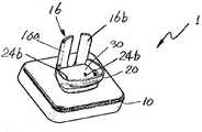
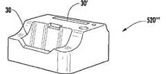
图1是扩展坞的扩展底座的立体图;FIG. 1 is a perspective view of an extension base of a docking station;
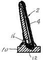
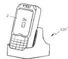
图2是在图1所示扩展底座容纳区域容纳有便携电子设备的扩展坞的第一工作位置;Fig. 2 is the first working position of the docking station containing the portable electronic device in the receiving area of the docking station shown in Fig. 1;
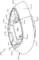
图3A和3B是根据第一个实施例所制的设备适配器(device adapter)的立体图;3A and 3B are perspective views of a device adapter (device adapter) made according to the first embodiment;
图4是装配了如图3A和3B所示的设备适配器的图1所示扩展坞的立体图;Figure 4 is a perspective view of the docking station shown in Figure 1 assembled with the device adapter shown in Figures 3A and 3B;
图5A和5B是图4所示扩展坞的第二工作位置的主视图和后视图,装配了如图4所示设备适配器和扩展坞,在所述设备适配器的容纳区域容纳了便携电子设备;5A and 5B are a front view and a rear view of a second working position of the docking station shown in FIG. 4 , assembled with the device adapter shown in FIG. 4 and the docking station, and a portable electronic device is accommodated in the accommodation area of the device adapter;
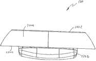
图6A到6G是根据第二个实施例形成的设备适配器的各种视图,其中图6A和6B是所述设备适配器的立体图;图6C到6G相应为图6A和6B所示设备适配器的俯视图、仰视图、主视图、后视图和侧视图。6A to 6G are various views of the device adapter formed according to the second embodiment, wherein FIGS. 6A and 6B are perspective views of the device adapter; FIGS. 6C to 6G are top views, respectively, of the device adapter shown in FIGS. 6A and 6B ; Bottom view, front view, rear view and side view.
图7A到7F为图6A到6G所示设备适配器第一部分的各种视图,其中图7A为设备适配器第一部分的立体图,图7B到7F为所述第一部分的相应俯视图、仰视图、主视图、侧视图和剖面图;7A to 7F are various views of the first portion of the device adapter shown in FIGS. 6A to 6G , wherein FIG. 7A is a perspective view of the first portion of the device adapter, and FIGS. 7B to 7F are respective top, bottom, front, and top views of the first portion; side and section views;
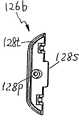
图8A到8F为图6A到6G所示设备适配器第二部分的各种视图,其中图8A为设备适配器第二部分的立体图,图8B到8F为所述第二部分的相应俯视图、仰视图、主视图、侧视图和剖面图;8A to 8F are various views of the second portion of the device adapter shown in FIGS. 6A to 6G , wherein FIG. 8A is a perspective view of the second portion of the device adapter, and FIGS. 8B to 8F are respective top, bottom, and Front view, side view and section view;
图9A到9E为图6A到6G所示设备适配器第三部分的各种视图,其中图9A为设备适配器第三部分的立体图,图9B到9E为所述第三部分的相应俯视图、仰视图、主视图、侧视图和剖面图;9A to 9E are various views of the third portion of the device adapter shown in FIGS. 6A to 6G , wherein FIG. 9A is a perspective view of the third portion of the device adapter, and FIGS. 9B to 9E are corresponding top, bottom, and bottom views of the third portion. Front view, side view and section view;
图10A到10C为装配了图6A到6G所示设备适配器的扩展坞的各种视图,其被用于第二工作位置以容纳便携电子设备;10A to 10C are various views of the docking station equipped with the device adapter shown in FIGS. 6A to 6G, which is used in a second working position to accommodate a portable electronic device;
图11所示为按照第三实施例制成的设备适配器;Figure 11 shows a device adapter made according to a third embodiment;
图12所示为装配了如图11所示设备适配器的扩展坞,其被用于第二工作位置以容纳便携电子设备;Figure 12 shows the docking station assembled with the device adapter shown in Figure 11, which is used in the second working position to accommodate the portable electronic device;
图13所示为图11所示设备适配器的变形;Figure 13 shows a deformation of the device adapter shown in Figure 11;
图14所示为根据第四实施例制成的设备适配器,其被用于容纳便携电子设备;Figure 14 shows a device adapter made according to a fourth embodiment, which is used to accommodate a portable electronic device;
图15为根据第五实施例制成的可堆叠适配器插入器的分解视图;Figure 15 is an exploded view of a stackable adapter inserter made in accordance with a fifth embodiment;
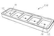
图16所示为根据第六实施例制成的装配有多个扩展坞的扩展坞模块;Figure 16 shows a docking station module assembled with multiple docking stations made according to a sixth embodiment;
图17所示为图16所示扩展坞模块的模块基座的立体图;Figure 17 is a perspective view of the module base of the docking station module shown in Figure 16;
图18A和18B为图16所示扩展坞的各种视图,其中图18B所示的扩展坞图示为配有设备适配器;18A and 18B are various views of the docking station shown in FIG. 16, wherein the docking station shown in FIG. 18B is shown with a device adapter;
图19所示为图18A和18B所示扩展坞被用于容纳便携电子设备;Figure 19 shows the docking station shown in Figures 18A and 18B being used to accommodate portable electronic devices;
图20所示为图16所示扩展坞模块的一个变形;Figure 20 shows a modification of the docking station module shown in Figure 16;
图21所示为图20所示扩展坞,其中所述扩展坞配有设备适配器;Figure 21 shows the docking station shown in Figure 20, wherein the docking station is equipped with a device adapter;
图22A和22B所示为图21所示扩展坞被用于在第一工作位置和第二工作位置容纳便携电子设备;22A and 22B show the docking station shown in FIG. 21 being used to accommodate portable electronic devices in a first working position and a second working position;
图23所示为图16所示扩展坞模块的另一个变形的分解视图;Figure 23 is an exploded view of another variation of the docking station module shown in Figure 16;
图24为图23所示扩展坞模块装配后的立体图;FIG. 24 is a perspective view of the assembled docking station module shown in FIG. 23;
图25所示为图23所示扩展坞模块处于充电和/或为不同便携电子设备进行导入和导出数据的操作位置;和Figure 25 shows the docking station module shown in Figure 23 in an operational position for charging and/or importing and exporting data for various portable electronic devices; and
图26A到26E所示为图16所示扩展坞模块的相应另一个变形,在扩展坞模块中使用设备适配器,且所述设备适配器用于在独立工作位置上容纳便携电子设备。Figures 26A to 26E show a corresponding further variation of the docking station module shown in Figure 16 in which a device adapter is used to accommodate a portable electronic device in a stand-alone working position.
具体实施方式Detailed ways
扩展坞(docking station)1和设备适配器(device adapter)20的各种实施例将会结合附图在下文中进行描述。在下列不同实施例的描述中,相类似的部件用相似的数字和下标来表示,且冗余的描述被省略。Various embodiments of the
此处所描述的不同扩展坞1被提供用于对不同的便携电子设备2中的可充电电池2’充电。电池充电操作可以通过直接对从相应便携电子设备2上被移除出来的可充电电池2’充电,或者当可充电电池2’留在便携电子设备2中时通过便携电子设备2对其充电。附加地或可选地,此处描述的扩展坞1还可以被提供为从不同便携电子设备2中导入或导出数据。尽管所述扩展坞1在各种附图中都被图示为桌面型,此处描述的扩展坞1并不限于此,其可以被挂在墙上、用于车中或者嵌入在仪表盘或电子设备中。附加地或可选地,尽管在各个附图中图示以移动电话作为便携电子设备2,但各种实施例并不限于使用这样的移动电话。此处描述的扩展坞1被设置为配合各种可充电电池2’和/或便携电子设备2使用,包括但不限于带或不带操作系统的手机、个人数据助理(PDA)、移动电脑、便携游戏机、MP3播放器、数码相机、数码摄像机、录音机、全球定位系统(GPS)、扫描仪或其他使用可充电电池的便携电子设备。The
图1所示为被设置为在电池充电过程和/或数据传输操作过程中用于各种可充电电池2’和/或便携电子设备2的扩展坞1的扩展底座(docking base)10。在一个实施例中,扩展底座10可制成与传统的充电器类似。在图1所示实施例中,扩展底座10具有容纳区域12,所述容纳区域12形成有接触口14,在充电过程和/或从便携电子设备导入与导出数据的过程中提供电源。在进行充电和/或数据转移操作的第一工作位置,与传统扩展坞类似,扩展底座10能直接容纳并保持(或固定)不配有壳套的便携电子设备2。Figure 1 shows a
如图1和2所示,扩展底座10的容纳区域12能被设置为用各种方法来容纳并保持便携电子设备2的一部分。尽管图2所示的便携电子设备2是直接被容纳于扩展底座10的容纳区域12中而不配有壳套4的,但是扩展底座10的容纳区域12可以被设置为容纳配有壳套4的便携电子设备2。附加地或可选地,扩展底座10的容纳区域12可以被设置为容纳从便携电子设备2上直接被移除出来的可充电电池2’。在一个实施例中,容纳区域12可以容纳包括设备接触口(未在图中显示)的便携电子设备2的一部分且允许该设备接触口接触容纳区域12内的接触口14。在一个实施例中,扩展底座10的容纳区域12可以被形成为具有充足容积的容纳腔12a以放置(或容纳)包括设备接口的便携电子设备2的充电部分。在图2所示实施例中,扩展坞10中的容纳腔12a可以被形成容纳便携电子设备2的底部。如本领域技术人员应该理解的那样,扩展底座10与扩展坞1可以被形成为各种其他形状以容纳其他不同便携电子设备2的接触口部分。As shown in FIGS. 1 and 2, the receiving
附加地或可选地,扩展底座10中的容纳区域12可以被形成用各种方法提供对于便携电子设备2的至少部分进行支撑(partial support)且在便携电子设备2被放置在容纳区域12后保持(或固定)其到位。举例来说,容纳区域12可以被设置为至少部分与便携电子设备2的主体部分接触,从而在充电过程和/或数据转移过程中提供支撑(support)。在一个实施例中,容纳区域12可以被形成为与便携电子设备2在一处或多处接触,从而在充电过程和/或数据转移过程中支撑并固定便携电子设备2到位。在另外一个实施例中,容纳区域12的至少一部分的形状和/或尺寸可以匹配便携电子设备2的主体部分。在进一步的实施例中,容纳区域12可以被形成为紧贴地适合于带设备接口的便携电子设备2的接口部分从而可以在充电过程和/或数据转移过程中保持(或固定)便携电子设备2到位。Additionally or alternatively, the
在扩展底座10上可以提供一个或多个附加支撑件16,从而在充电过程和/或数据转移过程中支撑并保持(或固定)便携电子设备2到位。在如图1所示实施例中,在充电过程和/或数据转移过程中,附加支撑件16被提供用于将便携电子设备2支撑在一个倾斜位置上,如图2所示。附加支撑件16可以与扩展底座10一体成型或者分开成型然后再被装配在容纳腔12a中。在如图1所示实施例中,附加支撑件16包括两个从扩展底座10向上延伸的叉部16a。在图2所示另一个实施例中,容纳腔12a被作为停止部件,能防止便携电子设备2的底部从容纳区域12滑出。如本领域技术人员应该理解的那样,容纳区域12、容纳腔12a和/或附加支撑件16可以被形成为各种形状,如在接下来的各实施例中描述的那样,在充电过程和/或数据转移过程中支撑并保持(或固定)便携电子设备2到位。One or more
扩展底座10的接触口14可以有任何的形状以连接形成于便携电子设备2内的设备接口。举例来说,标准USB型终端可以形成于扩展底座10中以匹配形成于移动电话中的标准USB型设备接口。在图1所示实施例中,容纳腔12a的底部12b上形成有接触口14。如本领域技术人员应该注意的那样,扩展坞1的接触口14可以被形成在扩展底座10中容纳腔12a的任何位置上,这取决于要被保持(或固定)的便携电子设备2上设备接口所处的位置。The
扩展坞1可以被形成为在扩展底座10上具有附加电气连接件与电路,从而将接触口14与外部电源相连接,从而在充电过程和/或数据转移过程中提供电源和/或将数据转移到便携电子设备2中。举例来说,扩展坞1可以包括连接件18,比如电源线,以连接任何不同的外部电源(未在图中显示),比如标准AC电源插座、车载12V电源或低压5V电源。在扩展底座10中也可以形成合适的电路用以将标准AC电源转化成便携电子设备2适用的电压源。在一个实施例中,连接件18可以具有USB终端,用以连接形成于电源适配器设备中的USB接口。附加地或可选地,连接件18可以连接扩展底座10与电脑设备上的匹配接触口以传输数据和提供电源。在一个实施例中,USB线可以被选择进行充电或数据传输操作,或者同时实现两者功能。如本领域技术人员应该注意的那样,为实现上述目的,可以使用不同的接口、充电电路和/或电气连接件。The
可选地,扩展底座10可以被形成具有与充电和/或数据传输操作相关的附加部件。举例来说,可在扩展底座10上形成一个或多个开关对充电和/或数据传输过程进行手工控制。另外,扩展底座10可以包括各种指示器向使用者指示充电和/或数据传输过程的状态。Optionally,
图2所示为扩展坞1的第一工作位置。在这样的第一工作位置中,扩展坞1在充电和/或数据传输过程中直接容纳并保持便携电子设备2。在一个实施例中,便携电子设备2直接被容纳在扩展底座10中的容纳腔12a中而没有壳套。扩展底座10中的接触口14与便携电子设备2中的设备接口电气连接,为便携电子设备2提供电源和/或从便携电子设备2中导入或导出数据。如上所讨论的那样,扩展底座10和/或扩展坞1可以被设置为容纳配有壳套4的便携电子设备2和/或直接从便携电子设备2上被移除出来的可充电电池2’。FIG. 2 shows the first working position of the
图3A和3B所示为根据第一实施例形成的设备适配器20。设备适配器20是可移除的,可在充电和/或数据传输过程中与扩展底座10配合使用。设备适配器20具有适配器主体22,被设置为由扩展底座10所支撑(supported)。适配器主体22可以包括底座部分22b,其适于被扩展底座10的容纳区域12所支撑,如图4所示。举例来说,底座部分22b被配合并保持(或固定)在扩展底座10的容纳腔12a中。Figures 3A and 3B show a
附加地或可选地,设备适配器20的底座部分22b可以被形成为防止底座部分22b在容纳腔12a内侧向移动的形状和/或尺寸。在一个实施例中,底座部分22b可以被形成为与容纳区域12的至少一个部分大致相同但相容的形状,且能被保持(或固定)于容纳区域中直到设备适配器20被使用者从容纳区域12上移除。在这样的情况下,底座部分22b能在没有其他进一步支撑的情况下,从扩展底座10中的设备适配器20处得到充分的支撑。设备适配器20和扩展底座10因此能形成整体装配(integrated assembly)。如本领域技术人员应该理解的那样,适配器主体22和底座部分22b能被形成为各种样式,如下将描述的那样,在充电和/或数据传输过程中,用以支撑设备适配器到位。Additionally or alternatively, the base portion 22b of the
设备适配器20能包括第一接触口和第二接触口24a、24b,第一接触口24a被形成于底座部分22b上与扩展底座10的接触口14电气连接,而第二接触口24b被形成于适配器主体22上与便携电子设备2上的接触口电气连接。第一接触口和第二接触口24a、24b可以与相应扩展底座10上的、和便携电子设备2上的接触口是相同类型或相匹配类型。The
举例来说,当扩展底座10上的接触口14为连接销形式,第一接触口24a可以被形成为相匹配的连接套筒24s,而第二接触口24b可以形成为包括相匹配的连接销24p。在一个实施例中,第二接触部分24b的连接销24p可以被形成为具有足够的长度,以通过壳套4并接触到便携电子设备2的接触口。在另外一个实施例中,第二接触口24b可以被形成为具有接触支撑,从而如以下实施例要描述的那样,支撑便携电子设备2上的接触口。如下面的各种实施例中要描述的那样,设备适配器的第一接触口和第二接触口24a、24b可以被形成为各种样式,比如USB型的接口。For example, when the
附加地或可选地,设备适配器的第一接触口和第二接触口24a、24b可以通过各种方式彼此电气连接,从而可以在充电和/或数据传输过程中将便携电子设备2与扩展底座10电气连接。在销钉类型的接触口中,比如上述实施例所述的,第一接触口24a的每个连接套筒24s可以与相应的第二接触口24b的连接销钉24p电气连接。第二接触口24b的连接销钉24p彼此分开且绝缘。附加地或可选地,第一接触口和第二接触口24a、24b可以如下所述的那样通过附加电路彼此电气连接。Additionally or alternatively, the first contact port and the second contact port 24a, 24b of the device adapter can be electrically connected to each other in various ways, so that the portable
在图3A和3B所示的实施例中,设备适配器20能进一步包括容纳区域30,其被设置为容纳并支撑便携电子设备2。在一个实施例中,设备适配器20的容纳区域30被设置为容纳并支撑配有壳套4的便携电子设备2。举例来说,容纳区域30可以在第二工作位置支撑配有壳套4的便携电子设备2的接口部分,如图5A和5B所示。在一个实施例中,设备适配器20上的容纳区域30可以被形成为容纳腔30a,其具有足够的容积以容纳配有壳套4的便携电子设备2的接口部分。在这样的情况下,使用者可以在不把便携电子设备2去除其壳套4的情况下就对其进行充电,从而简化了充电和/或数据传输操作。In the embodiment shown in FIGS. 3A and 3B , the
附加地或可选地,设备适配器20上的容纳区域30被形成为在充电和/或数据传输操作中,支撑并保持(或固定)结合壳套4的便携电子设备2到位。在一个实施例中,当结合壳套4的便携电子设备2被置于位于设备适配器20中的容纳腔30a中时,容纳腔30a可以被形成为部分接触配在便携电子设备2上的壳套4。举例来说,在充电和/或数据传输过程中,容纳腔30a的部分可以被形成为部分接触并支撑结合壳套4的便携电子设备2的下方前部。在如图5A充分展示的一个实施例中,容纳腔30a的前壁可以被置于接触到结合壳套4的便携电子设备2的下方前部。容纳腔30a的该前壁能相对于便携电子设备2的下方前部施加偏压力,从而防止便携电子设备2在充电和/或数据传输过程中滑出。Additionally or alternatively, the receiving
在图5A和5B所示另外一个实施例中,容纳腔30a被类似地形成,并与配有壳套4的便携电子设备2的底部相匹配。如本领域技术人员应该理解的那样,容纳区域30可以形成为各种其他式样,比如结合下面一个或多个附加实施例所将要描述的那样。In another embodiment shown in FIGS. 5A and 5B , the
在一个实施例中,容纳腔30a能被围壁32所环绕,所述围壁可以部分地紧贴环绕配有壳套4的便携电子设备2的下部。能在充电和/或数据传输操作中,围壁32被形成为至少部分地支撑并保持(或固定)便携电子设备2和壳套4到位(参看图5A和5B)。举例来说,围壁32是连续壁,在第二工作位置上至少部分环绕结合壳套4的便携电子设备2的下部。在一个实施例中,围壁32可以是杯状的。在另一个实施例中,围壁32可以具有至少一个开口32a以放置位于扩展底座10上的附加支撑件16。如本领域技术人员应该理解的那样,设备适配器20上的容纳区域30可以被形成为各种其他式样,如接下来的各实施例所描述的那样。In one embodiment, the
如图4所示,设备适配器20可被可移除地配合在如图1所示的扩展底座10上。举例来说,设备适配器20的底座部分22b可以被放置于扩展底座10的容纳区域12内。在一个实施例中,底座部分22b可以被插入并保持(或固定)在扩展底座10的容纳腔12a中。底座部分22b和容纳腔12a是如此形成的:所述底座部分22b被限制为相对于容纳腔12a不能侧向移动。在这样的情况下,设备适配器20的底座部分22b可以被紧贴地嵌入在扩展底座10的容纳腔12a中,从而形成整体装配,这将在第二工作位置顺序为便携电子设备2提供足够的支撑,如图5A和5B所示。As shown in FIG. 4 ,
当设备适配器20被配合在扩展坞1的扩展底座10中时,设备适配器20上的第一接触口24a能与扩展底座10上的接触口14电气连接。结果,设备适配器20上的第二接触口24b能与扩展坞1的扩展底座10上的接触口14电气连接。如图4所示,设备适配器20上的第二接触口24b相对于扩展底座10上的接触口14处于较高的位置上。在一个实施例中,设备适配器20上的容纳区域30位于扩展底座10的容纳区域12和/或容纳腔12a之上。相比于扩展底座10的容纳区域12,设备适配器20的容纳区域30对用扩展坞1进行充电和/或数据传输操作的便携电子设备2的尺寸和/或形状的要求(或限制)较低。因此,设备适配器20上的第二接触口24b能与各种尺寸和/或式样的便携电子设备2相连接,比如配在壳套4中的便携电子设备2,如图5A和5B所示。When the
在如图5A和5B所示实施例中,被装配的扩展底座10和设备适配器20可以在充电和/或数据传输操作的第二工作位置被用于保持(或固定)配有壳套4的便携电子设备2。在这样的第二工作位置,便携电子设备2与其配的壳套4能被放置于设备适配器20的容纳区域30中,所述设备适配器20被扩展底座10的容纳区域12所保持(或固定)。在一个实施例中,结合壳套4的便携电子设备2的下部被放置于并被保持(或固定)于设备适配器20的容纳腔30a内。便携电子设备2上的设备接口能被用于与设备适配器上的第二接触口24b电气连接。In the embodiment shown in FIGS. 5A and 5B , the assembled
附加地或可选地,结合壳套4的便携电子设备2能被其他支撑机构所支撑,从而在充电和/或数据传输操作的第二工作位置上进一步稳定结合壳套4的便携电子设备2。在图5A和5B所示的一个实施例中,结合壳套4的便携电子设备2被附加支撑件16所支撑,以提供额外的稳定性。在图5A所示另外一个实施例中,围壁32可以包裹住结合壳套4的便携电子设备2的底部,从而防止该底部向前滑动。如本领域技术人员应该理解的那样其他的支撑设备也可以被采用以实现相同的目的。Additionally or alternatively, the portable
如图5A和5B所示,便携电子设备2的壳套4可以被制成各种式样以保护便携电子设备2的整体性或增强其外观吸引力。举例来说,壳套4可以被制成各种形状用于紧贴在便携电子设备2上。壳套4是可移除的,配在便携电子设备2,覆盖便携电子设备2的一部分,从而起保护作用,同时可展现其显示屏和/或键盘,能进行数据输入。在一个实施例中,壳套4由透明材料制成,允许使用者通过壳套4看到显示屏和/或通过壳套4在便携电子设备2上操作键盘。壳套4可以由各种材料制成,包括但不限于:塑料、橡胶、皮革、纸或纤维材料。As shown in FIGS. 5A and 5B , the
附加地或可选地,便携电子设备2的壳套4可以被制成各种式样和/或尺寸以保护便携电子设备2的整体性或增强其外观吸引力。在一个实施例中,壳套4可以具有厚度范围,这取决于各种因素,比如使用便携电子设备2的环境和用户喜好。举例来说,壳套4的厚度可以在大约2mm到大约3mm的范围内。在一个实施例中,壳套4的厚度可以在大约5mm到大约6mm之间以增强对于便携电子设备2的保护,比如被用于建筑工地或者其他地点,在这些使用地点中,便携电子设备2被暴露在严酷的天气或粗陋的使用条件下。在另一个实施例中,壳套4的厚度可以是大约1mm,从而被壳套4保护的便携电子设备2会变得薄而轻巧。壳套4可以被设计为具有各种其他厚度。Additionally or alternatively, the
尽管图5A和5B所示为设备适配器20的容纳区域30适于容纳并支撑配有壳套4的便携电子设备2,但是容纳区域30的设置并不限于此。举例来说,设备适配器20的容纳区域30可以被设置为容纳不配有壳套4的便携电子设备2。附加地或可选地,设备适配器20的容纳区域30可以被设置为直接容纳从便携电子设备2上被移除出来的可充电电池2’。Although FIGS. 5A and 5B show that the receiving
图6A到6G所示为设备适配器120的第二个实施例,下面的描述和附图将会展示更多涉及设备适配器120的接触口、电路和电气接触的细节。如图6A和6B所充分展示的那样,设备适配器120包括第一接触口和第二接触口124a、124b,其与扩展底座10的接触口和便携电子设备2上的接触口在充电和/或数据传输操作中电气连接。在一个实施例中,第一接触口124a被形成在底座部分122b上,并与扩展底座10上的那些接触口14相匹配。如本领域技术人员应该理解的那样,第一接触口124a可以被设置为各种形式,比如USB接口或者雌性销钉型接触口(female pin-type port),用以进行充电和/或数据传输操作。A second embodiment of the
第二接触口124b位于设备适配器120的适配器主体122上,以连接便携电子设备2中的设备接触口。在如图6A和6B所示实施例中,第二接触口124b能包括接触支撑件124c和被支撑在接触支撑件124c中的电气接触件124m。第二接触口124b的接触支撑件124c可以在第二工作位置(见图10A到10C)被形成为用于支撑便携电子设备的接触口。在一个实施例中,第二接触口124b的接触支撑件124c具有至少相当于壳套4厚度的高度。这样的接触支撑件124c可以延伸并穿过壳套4的开口,在充电和/或数据传输操作时,接触到便携电子设备2中的接触口。The second contact port 124 b is located on the
第二接触口124b的电气接触件124m可以被形成与便携电子设备2上的设备接触口相匹配。在一个实施例中,电气接触件124m可以是任何种的雄性接触,比如连接销钉124p,形成有足够长度从而在第二工作位置接触到便携电子设备2的接触口。在另外一个实施例中,电气接触件124m可以被形成为弹簧接触,从而在第二工作位置,便于在第二接触口124b和便携电子设备2的接触口之间形成电气接触。各种类型的接触口,只要它们与便携电子设备2的设备接触口相匹配,比如USB接口,都可以在充电和/或数据传输操作中被附加用于销钉类型或弹簧类型的第二接触口124b上,或者被用在销钉类型或弹簧类型的第二接触口124b的位置上。The
在图6A到6G所示实施例中,设备适配器120的适配器主体122包括从容纳区域30开始侧向延伸并环绕容纳区域30的裙部122s(另见图7F所示剖面图)。裙部122s还包括形成为各种样式的围壁122w。在一个实施例中,围壁122w沿圆周方向连续延伸形成闭合的壁。附加地或可选地,围壁122w可以在裙部122s轴向上具有直的、斜的或者有角度的形状。在图6A到6G所示实施例中,裙部122s的围壁122w为有倾斜的外形。如本领域技术人员应该理解的那样,围壁122w可以被形成为其他外形,比如下述的实施例或变形中所述的那样。In the embodiment shown in FIGS. 6A to 6G , the
在一个实施例中,设备适配器120的裙部122s被设置为支撑扩展底座10上的设备适配器120。举例来说,裙部122s能向其底缘122u张开(或扩大)。当设备适配器120被装配在扩展底座10上时,张开(或扩大)的底缘122u能朝离开容纳区域12侧向延伸。在这样的情况下,当设备适配器120配合扩展底座10被使用时,张开(或扩大)的底缘122u能靠在(rest on)扩展底座10的顶部平面上。如本领域技术人员应该理解的那样,裙部122s能被形成为各种其他外形,比如下述的实施例或变形中所述的那样。In one embodiment, the skirt 122s of the
附加地或可选地,裙部122s的顶缘122t可以被形成为各种形状。如图6A和6B所充分展示的那样,裙部122s的顶缘122t的至少一个部分能被形成为符合(或跟踪)(track)结合壳套4的便携电子设备2的下部的轮廓部分(还可参见图10A)。在一个实施例中,裙部122s的顶缘122t的这个部分因此能在设备适配器120被用于第二工作位置时,将结合壳套4的便携电子设备2的下部支撑到位。在图6C和10A所示的实施例中,裙部122s的顶缘122t的前半部分可以被形成为与结合壳套4的便携电子设备2的下部的前半部分相匹配,从而在设备适配器120的正常使用中将其保持(或固定)到位。Additionally or alternatively, the
在图6A到6C所充分展示的另一个实施例中,一个或多个侧突起部122p、122q被形成为从裙部122s的顶缘122t向内延伸。在一个实施例中,一个或多个侧突起部122p、122q可以在设备适配器120的正常使用中,为结合的便携电子设备2和壳套4提供额外的支撑(另外参看图10A和10B)。举例来说,侧突起部122p、122q可以与裙部122s的顶缘122t的前部一起作用,保持(或固定)结合壳套4的便携电子设备2。结果,在充电和/或数据传输操作中,结合壳套4的便携电子设备2能被防止其在设备适配器120中不利(undesired)的侧向移动。附加地或可选地,在充电和/或数据传输操作中,当设备适配器120被正常使用时,位于裙部122s的顶缘122t上的侧突起部122p、122q能盖住或密封设备适配器120的内部。In another embodiment, best illustrated in Figures 6A to 6C, one or
在图6A到6C所充分展示的进一步的实施例中,顶缘122t的后部可以被形成为具有与扩展底座10上的一个或多个附加支撑件16配合的外形。举例来说,顶缘122t的后部具有弯曲的部分122c与附加支撑件16的弯曲部分16c匹配。在设备适配器20被装配在扩展底座10上之后(见图10B),在顶缘122t上这样弯曲的后部122c环绕附加支撑件16的弯曲部分16c,此时侧突起部122q(位于弯曲的后部122c之间)延伸到附加支撑件16的叉部延长16a之间。这样的设置能在充电和/或数据传输操作中将设备适配器120安全固定在扩展底座10上,并防止设备适配器120侧向移离工作位置。In a further embodiment, best illustrated in FIGS. 6A to 6C , the rear portion of the
设备适配器120可以通过各种方法制成。在一个实施例中,设备适配器120可以通过将多个适配器部件126a、126b、126c组装而成,这些部件可以被分开形成,以便利设备适配器120的制造。
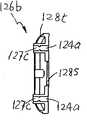
图7A到7F为设备适配器120的第一适配器部件126a的各个视图,包括如上所述的第一接触口124a(没有?)、第二接触口124b、容纳区域30和裙部122s。如图7F的剖视图所示,设备适配器120的第一适配器部件126a还包括电气连接件127,用以将位于第二接触口124b中的电气接触124m与第一接触口124a连接。如图6A和7A到7F所充分展示的那样,电气连接件127从第二接触口124b中的电气接触124m延伸到第一适配器部件126a的底部,具有自由端127e(见图7F的剖视图)。电气连接件127的自由端127e能延伸到形成于设备适配器120的第二和第三适配器部件126b、126c上的第一接触口124a中。7A to 7F are various views of the
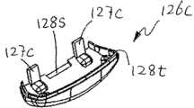
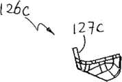
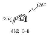
图8A到8F所示为设备适配器120的第二适配器部件126b的细节。图9A到9E所示为设备适配器120的第三适配器部件126c的细节。(错?)第二和第三适配器部件126b、126c可以互相连接并与设备适配器120的第一适配器部件126a连接,以构成设备适配器120。一个或多个连接件接触口127c可以至少被形成在第二和第三适配器部件126b、126c上。在一个实施例中,设备适配器120的第二和第三适配器部件126b、126c中的每一个都能被形成为部分的连接件接触口,其能结合形成一个或者多个如下描述的连接件接触口127c。Details of the
当设备适配器120的第二和第三适配器部件126b、126c互相结合(或连接),就形成了连接件接触口127c。当第二和第三适配器部件126b、126c与第一适配器部件126a结合(或连接)时,连接件接触口127c适于容纳电气连接件127的自由端127e,以形成第一接触口124a。所形成的第一接触口124a与扩展底座10上的接触口14可电气连接。各种类型的第一接触口124a,比如USB型接触口,可以代替销钉类型的接触口124a或作为附加使用,只要它们能与扩展底座10上的接触口14匹配。When the second and
设备适配器120的各适配器部件126a、126b、126c可以分别形成并组装在一起形成设备适配器120。在一个实施例中,适配器部件126a、126b、126c分别从塑料材料成型。在适配器部件126a、126b、126c上提供有一个或多个紧固件以便利其之间的连接。在一个实施例中,在第二和第三适配器部件126b、126c上形成有一个或多个扣式紧固件128s以连接其他部分。在另外一个实施例中,第二和第三适配器部件126b、126c可以被形成有扣式紧固件128t以连接设备适配器120的第一适配器部件126a上与之互补的扣式紧固件。在进一步的实施例中,第一适配器部件126a上及在至少第二和第三适配器部件126b、126c中的一个上形成有一个或多个插入式紧固件128p以连接其他不同部分。如本领域技术人员应该理解的那样,各种不同的其他类型的紧固件也可以被用于实现相同目的。The
当设备适配器120的各不同部件126a、126b、126c彼此连接之后,第二和第三适配器部件126b、126c形成了设备适配器120的底座部分122b,如图6G所示。在最后形成的设备适配器120中,第一雌性接触口124a被形成及位于设备适配器120的底座部分122b上,且可与扩展底座10的雄性接触口14相连接。The second and
图10A到10C所示在第二工作位置的充电和/或数据传输操作中,为用于扩展底座10上容纳结合壳套4的便携电子设备2的设备适配器120。扩展底座10类似于上述实施例描述的扩展底座10。10A to 10C show the
图11所示为根据第三个实施例的设备适配器220。在这个实施例中,围壁222w具有轴向平坦的外形,如图12充分展示的那样。Figure 11 shows a
图13所示为图11所示设备适配器220的变形。在此变形中,附加支撑件可以被提供,用以在充电和/或数据传输操作中,保持结合的便携电子设备2和壳套4到位。在一个实施例中,在适配器主体222上可以形成有支撑壁332,从而在充电和/或数据传输操作中,保持结合的便携电子设备2和壳套4的接触部分到位。支撑壁332位于适配器主体222上方并在一个或多个位置上保持与结合的便携电子设备2和壳套4的接触。在图13所示实施例中,支撑壁332是连续的。在另一个实施例中,支撑壁332可以是多个不连续的部分。如本领域技术人员应该注意支撑壁332可以被形成为各种不同的形式,从而为结合的便携电子设备2和壳套4在充电和/或数据传输操作中提供附加支撑。FIG. 13 shows a modification of the
图14所示为根据第四个实施例形成的设备适配器420。在这个实施例中,设备适配器420的适配器主体422具有裙部422s向下延伸到底缘422b处。设备适配器420的裙部422s具有高于扩展底座10裙部(其标号为裙部422)的高度。因此,当扩展底座10和设备适配器420组装在一起并被用于第二工作位置时,裙部422s向侧向延伸超过扩展底座10,此时裙部422s的围壁422w包围并掩盖住扩展底座10,如图14所示。Figure 14 shows a
在进一步的实施例中,上述任何一种设备适配器20、120、220都能被形成具有多个第二接触口24b或者124b,能与多个便携电子设备2相连接。举例来说,设备适配器20可以被形成为具有至少有两个第二接触口24b。每个第二接触口24b可以与第一接触口24a电气连接,而第一接触口24a可顺序地与扩展底座10上的接触口14电气连接。根据与第二接触口24b连接的便携电子设备2的类型,合适的电路可以被用于调节第二接触口24b的输出电压值。这样的多个第二接触口24b可以被设置为与不同于便携电子设备2的便携电子设备电气连接。举例来说,设备适配器20可以被用于同时对便携电子设备2和便携电子设备2的备用(spare)电池(未在图中显示)进行充电操作。假如需要的话,附加的支撑装置,比如围壁32,可以被用于在充电操作中对便携电子设备2和/或其备用电池提供支撑。In a further embodiment, any of the above-mentioned
图15所示为进一步的实施例,其中提供了多个可堆叠的适配器插入件40a、40b、40c可以与图3A和3B所示的设备适配器20一起使用。举例来说,一个或多个这样的可堆叠的适配器插入件40a、40b、40c可以形成为配合在设备适配器20的容纳区域30中。在一个实施例中,这样的可堆叠的适配器插入件40a、40b、40c每一个都可以被设置为支撑配有不同厚度的壳套4或不配有壳套4的便携电子设备2。在另一个实施例中,一个或多个这样的可堆叠的适配器插入件40a、40b、40c可以被设置为直接支撑从相应便携电子设备2上被移除出来的可充电电池2’。在图15所示实施例中,每个可堆叠的适配器插入件40a、40b、40c可以被形成为有相应的孔42a、42b、42c,允许便携电子设备2上的设备接触口接触到设备适配器20上的第二接触口24b。当一个或多个这样的可堆叠的适配器插入件40a、40b、40c配合设备适配器20一起被使用时,这样的可堆叠的适配器插入件40a、40b、40c可以改变容纳区域30的尺寸以容纳配有不同厚度的壳套4或不配有壳套4的便携电子设备2。Figure 15 shows a further embodiment in which multiple stackable adapter inserts 40a, 40b, 40c are provided for use with the
在一个实施例中,最外层的适配器插入件40a具有外表面44a可以紧贴地配合在设备适配器20的容纳区域30中。最外层的适配器插入件40a的内部腔体46a的形状和尺寸可以被形成为紧贴地配合配有较薄壳套4的便携电子设备2。当这样最外层的适配器插入件40a被置于设备适配器20的容纳区域30中并与扩展底座10一起被使用时,结合的扩展底座10、设备适配器20和最外层的适配器插入件40a可以容纳并保持配有较薄壳套4的便携电子设备2。In one embodiment, the outermost adapter insert 40 a has an outer surface 44 a that snugly fits within the receiving
在最外层的适配器插入件40a和最内层适配器插入件40c中可以提供一个或多个可堆叠的中间层适配器插入件40b,如下文将要详细描述的那样。每个中间位置适配器插入件40b具有外部表面44b,可以被形成为紧贴地配合在相邻的较大尺寸的适配器插入件40a,40b中。在图15所示实施例中,中间层适配器插入件40b被形成为紧贴地配合在最外层的适配器插入件40a的内部腔体46a中。One or more stackable intermediate adapter inserts 40b may be provided in the outermost adapter insert 40a and the innermost adapter insert 40c, as will be described in detail below. Each intermediate position adapter insert 40b has an exterior surface 44b that may be formed to fit snugly within an adjacent larger sized adapter insert 40a, 40b. In the embodiment shown in FIG. 15, the intermediate adapter insert 40b is formed to fit snugly within the interior cavity 46a of the outermost adapter insert 40a.
附加地或可选地,每个中间层适配器插入件40b的内部腔体46b被形成为紧贴地配合在相邻的较小尺寸的适配器插入件40b、40c中。在图15所示实施例中,中间位置适配器插入件40b的内部腔体46b被形成为紧贴地配合在最里面的适配器插入件40c中。当最外层的适配器插入件40a配合中间层适配器插入件40b使用时,结合的扩展底座10、设备适配器20和适配器插入件40a、40b可以支撑配有更薄的壳套4或不配有壳套4的便携电子设备2。Additionally or alternatively, the interior cavity 46b of each intermediate adapter insert 40b is formed to snugly fit within an adjacent smaller sized adapter insert 40b, 40c. In the embodiment shown in Figure 15, the interior cavity 46b of the intermediate position adapter insert 40b is formed to fit snugly within the innermost adapter insert 40c. When the outermost adapter insert 40a is used with the middle adapter insert 40b, the combined
最里面的适配器插入件40c可以被形成为紧贴地配合在最小的中间位置适配器插入件40b内部。最里面的适配器插入件40c的内部腔体46c的形状和尺寸可以被形成为容纳并支撑配有最薄的壳套4的便携电子设备2。当最里面的适配器插入件40c与一个或多个中间位置适配器插入件40b和最外层的适配器插入件40a配合使用时,结合的扩展底座10、设备适配器20和适配器插入件40a、40b、40c可以支撑配有最薄的壳套4的便携电子设备2。The innermost adapter insert 40c may be formed to fit snugly inside the smallest intermediate adapter insert 40b. The inner cavity 46c of the innermost adapter insert 40c may be shaped and dimensioned to accommodate and support the portable
可堆叠的适配器插入件40a、40b、40c的厚度可以取决于不同的特殊便携电子设备2可用的不同壳套4的厚度而决定。适配器插入件40a、40b、40c可以被形成为直接支撑或者另外结合起来支撑便携电子设备2和选择的壳套4的组合体。当一个或多个这样的可堆叠的适配器插入件40a、40b、40c被结合起来与设备适配器20一起使用,这样的可堆叠的适配器插入件40a、40b、40c可以改变容纳配有不同厚度壳套4的便携电子设备2的容纳区域30的大小。当不在设备适配器20的容纳区域30中使用这样的可堆叠的适配器插入件40a、40b、40c时,容纳区域30可以容纳并支撑结合的最厚壳套4和便携电子设备2,正如上述实施例中描述的那样。The thickness of the stackable adapter inserts 40a, 40b, 40c can be determined depending on the thickness of the
在另一个实施例中,适配器插入件40a、40b、40c可以被形成为被设备适配器20的容纳区域30所容纳并支撑。举例来说,适配器插入件40a、40b、40c可以具有相应的外表面44a、44b、44c,形成为紧贴地配合在设备适配器20的容纳腔30a内部。相应的适配器插入件40a、40b、40c的内部腔体46a、46b、46c的形状和尺寸可以如上所述,容纳不同的便携电子设备2和/或可充电电池2’。当使用这些适配器插入件40a、40b、40c和设备适配器20时,可以在同样一个扩展底座10上实现对于不同类型的便携电子设备2和/或可充电电池2’的充电和/或数据传输操作。举例来说,相应适配器插入件40a、40b、40c的内部腔体46、46、46的形状和尺寸可以容纳并保持移动电话、MP3播放器和多余电池。在另一个实施例中,相应适配器插入件40a、40b、40c的内部腔体46、46b、46c的形状和尺寸可以容纳并保持配有不同厚度的壳套4或者不配有壳套4的便携电子设备2。In another embodiment, the adapter inserts 40 a , 40 b , 40 c may be formed to be received and supported by the receiving
图16所示为根据第五个实施例制成的扩展坞模块500。扩展坞模块500可以被形成为具有多个扩展坞501,其类似于上述的扩展坞1。举例来说,正如接下来将要进一步描述的那样,多个扩展坞501的每一个具有被配置为可移除地容纳设备适配器520的容纳区域12。尽管图16中的扩展坞模块500所示为具有五个扩展坞501,本领域技术人员应该注意扩展坞模块500可以被形成为具有不同数量的扩展坞501。Figure 16 shows a
如图17所示,扩展坞模块500可以具有单片的扩展底座510,其可以通过将多个扩展坞501的底座结合而成。单片的扩展底座510可以被形成为多个容纳区域12,其中可以如上所述提供接触口14。在图17所示实施例中,单片的扩展底座510的多个容纳区域12可以被形成基本同样大小。在这样的情况下,单片的扩展底座510的容纳区域12的任何一个可以被用于容纳具有相配底座部分522b的设备适配器520,从而简化了扩展坞模块500的装配。As shown in FIG. 17 , the
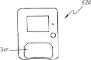
图18A和18B所示为与上述或下述描述的设备适配器20、120、220类似的这样的设备适配器520。在一个实施例中,各种设备适配器520具有大致相同的底座部分522b。在这样的情况下,各种设备适配器520的任何一个都可以被用于单片的扩展底座510上,从而简化了扩展坞模块500的装配并增加了设备适配器520的互换性。在另一个实施例中,单片的扩展底座510上的容纳区域12被类似地形成,各种设备适配器520可选地被用于单片的扩展底座510的任何容纳区域12上,从而提高了设备适配器520的互换性,并简化了电池充电和/或数据传输操作。Figures 18A and 18B illustrate such a
用于扩展坞模块500的多个设备适配器520具有可以被形成为容纳不同形状和尺寸的便携电子设备2的不同容纳区域30。如上描述,这样的设备适配器520的容纳区域30可以被设置为容纳配有或者不配有壳套4的便携电子设备2。附加地或可选地,设备适配器520可以被设置为具有容纳区域30’以容纳直接从便携电子设备2上移除下来的可充电电池2’。一个或多个可堆叠的适配器插入件40可以配合设备适配器520使用,如图18B所示。多个设备适配器520和/或一个或多个可堆叠的适配器插入件40上的不同容纳区域30能增加扩展坞模块500在扩展坞模块500向不同便携电子设备2充电和/或向不同便携电子设备2转移数据的操作中的功能。The plurality of
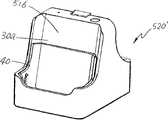
在图19所示的可选实施例中,一个或多个设备适配器520可以被用于不配有扩展底座510的独立场合。在这样的情况下,设备适配器520可以被用作扩展底座。举例来说,设备适配器520可以被设置为通过导线连接标准电源(举例来说,标准AC输出、车载12V电源或者低压5V电源)。In an alternative embodiment shown in FIG. 19 , one or
图20所示为如上描述的扩展坞模块500的变形500’。扩展坞模块500’可以具有单片的扩展底座510,如上实施例中所述。如图21充分展示的那样,扩展坞模块500’中的设备适配器520’可以被形成为在扩展坞模块500的操作中为便携电子设备2提供附加的稳定性。在一个实施例中,设备适配器520’的支撑件516可以形成在设备适配器520’中,界定容纳腔30a的后壁。在图21所示实施例中,适配器插入件40可以被用于配合设备适配器520’使用。Figure 20 shows a variation 500' of the
图22A和22B所示为可选实施例,其中设备适配器520’在独立场合,被用作扩展坞,不使用扩展底座510。举例来说,设备适配器520’可以适于在充电和/或数据传输操作时容纳便携电子设备2。在图22A所示实施例中,配有壳套4的便携电子设备2直接被容纳在设备适配器520’的容纳腔30a中。如图22B所示实施例中,适配器插入件40与设备适配器520’配合使用以容纳未配有壳套4的便携电子设备2。图22B也图示了设备适配器520’可以被形成为配有附加容纳腔30’以容纳附加设备。举例来说,设备适配器520’中的附加容纳腔30’可以被设置为在电池充电和/或数据传输操作中容纳便携电子设备2的多余电池并对其进行充电。Figures 22A and 22B illustrate an alternative embodiment in which the device adapter 520' is used as a docking station in a stand-alone application, without the use of the
当设备适配器520’在独立场合被用作扩展坞时,电源线可以被提供,用以将设备适配器520’和标准电源(比如标准AC输出、车载12V电源或者低压5V电压)电气连接。When the device adapter 520' is used as a docking station in a stand-alone situation, a power cord can be provided to electrically connect the device adapter 520' to a standard power source (such as a standard AC output, a vehicle 12V power supply, or a low voltage 5V voltage).
图23为图16所示扩展坞模块500的另一个变形500”的展开视图。在这个扩展坞模块500”中,不同的设备适配器520、520’被提供,被形成为如上述那样容纳不同类型的便携电子设备2。一个或多个设备适配器520、520’配合在单片扩展底座510的容纳区域12中,是可移除的,如图24所示。Figure 23 is an expanded view of another
如图25所示,扩展坞模块500”中的设备适配器520可以被用于容纳移动电话(比如手机或智能电话)。附加地或可选地,设备适配器520’可以被用于容纳移动电脑或扫描仪。在一个实施例中,设备适配器520’中的支撑件516可以为更高和/或更重的物品提供附加支撑。As shown in Figure 25, the
图26A所示为图16所示扩展坞模块500的另一个变形500”’。在这个实施例中,扩展坞模块500”’的扩展底座510可以被形成为支撑多个设备适配器520”’,520””。在图26B所示实施例中,扩展坞模块500”’的设备适配器520”’如图所示,除了上述连接设备适配器520的容纳区域30之外,还具有至少一个容纳腔30’。这样的电池容纳腔30’可以被用于在充电和/或数据传输操作中为可充电电池2’进行充电。在一个实施例中,可充电电池2’可以是便携电子设备2的多余电池。FIG. 26A shows another
在设备适配器520”’中可以具有附加的电器元件和电路。举例来说,在设备适配器520”’上可以形成有一个或多个指示器,指示便携电子设备2和/或电池2’的充电状态。在另外的实施例中,一个或多个指示器可以被用于指示设备适配器520”’的电源状态。Additional electrical components and circuits may be present in the
图26C到26E所示为在独立场合用于对便携电子设备2进行充电的设备适配器520”’,没有扩展底座510。如上所述,电源线可以被用于将设备适配器520”’和标准电源(比如标准AC输出、车载12V电源或者低压5V电压)电气连接。附加地或可选地,设备适配器520”’可以被用于在对便携电子设备2进行充电和/或数据传输的操作中对电池2’进行充电。Figures 26C to 26E
在图26C所示实施例中,便携电子设备2没有配备壳套,直接被设备适配器520”’所容纳。在一个实施例中,适配器插入件40可以被用于在充电和/或数据传输操作中协助支撑便携电子设备2。在图26D和26E所示实施例中,设备适配器520”’适于容纳配有各种壳套4的便携电子设备2。In the embodiment shown in FIG. 26C , the portable
如图26A所示,扩展坞模块500”’的设备适配器520”’可以被设置为具有多个电池容纳腔30’。举例来说,额外的电池容纳腔30’可以在充电和/或数据传输操作中,被设置为容纳便携电子设备2的多余电池并对其进行充电。在图26A所示实施例中,扩展坞模块500”’的设备适配器520”’被图示为仅具有电池容纳腔30’。As shown in FIG. 26A, the
因此,此处所图示、描述和指出的是应用于优选实施例的本发明的新颖特征,可以理解的是,本领域技术人员在它们的操作中,在图示设备上的形式上和细节上的各种去除、替代和改变都可以在不背离本发明本质的基础上做出。举例来说,明确的所有可以实现相同目的的元素和/或方法步骤的组合,可以实现相同目的,均落在本发明的保扩范围之内。另外,值得注意的是联系本发明保护的形式、实施例的任何结构和/或元素和/或所示方法和/或描述的方法可以结合其他设计。因此,意在只限于按下文的权利要求的范围来保护本发明。Thus there has been illustrated, described and indicated herein the novel features of the invention as applied to the preferred embodiment, and it will be understood that those skilled in the art in their operation would appreciate the form and detail on the illustrated device. Various omissions, substitutions and changes can be made without departing from the essence of the invention. For example, all explicit combinations of elements and/or method steps that can achieve the same purpose, can achieve the same purpose, and all fall within the protection scope of the present invention. In addition, it should be noted that any structures and/or elements of the embodiments and/or methods shown and/or described in connection with the protected forms of the present invention may be combined with other designs. Accordingly, it is intended that the invention be protected only in accordance with the scope of the following claims.
Claims (20)
Priority Applications (1)
| Application Number | Priority Date | Filing Date | Title |
|---|---|---|---|
| CN201610949582.7ACN107492918B (en) | 2009-10-20 | 2010-10-20 | Docking station and device adapter for same |
Applications Claiming Priority (4)
| Application Number | Priority Date | Filing Date | Title |
|---|---|---|---|
| US25331809P | 2009-10-20 | 2009-10-20 | |
| US61/253,318 | 2009-10-20 | ||
| US30330810P | 2010-02-10 | 2010-02-10 | |
| US61/303,308 | 2010-02-10 |
Related Child Applications (1)
| Application Number | Title | Priority Date | Filing Date |
|---|---|---|---|
| CN201610949582.7ADivisionCN107492918B (en) | 2009-10-20 | 2010-10-20 | Docking station and device adapter for same |
Publications (1)
| Publication Number | Publication Date |
|---|---|
| CN102044896Atrue CN102044896A (en) | 2011-05-04 |
Family
ID=43500073
Family Applications (3)
| Application Number | Title | Priority Date | Filing Date |
|---|---|---|---|
| CN2010105403462APendingCN102044896A (en) | 2009-10-20 | 2010-10-20 | Docks and Device Adapters for Docks |
| CN2010205965662UExpired - LifetimeCN201937287U (en) | 2009-10-20 | 2010-10-20 | Docking station, equipment adapter for docking station and accessory package |
| CN201610949582.7AActiveCN107492918B (en) | 2009-10-20 | 2010-10-20 | Docking station and device adapter for same |
Family Applications After (2)
| Application Number | Title | Priority Date | Filing Date |
|---|---|---|---|
| CN2010205965662UExpired - LifetimeCN201937287U (en) | 2009-10-20 | 2010-10-20 | Docking station, equipment adapter for docking station and accessory package |
| CN201610949582.7AActiveCN107492918B (en) | 2009-10-20 | 2010-10-20 | Docking station and device adapter for same |
Country Status (5)
| Country | Link |
|---|---|
| US (1) | US10148104B2 (en) |
| EP (2) | EP2315322A1 (en) |
| CN (3) | CN102044896A (en) |
| DE (1) | DE202010018602U1 (en) |
| HK (1) | HK1144143A2 (en) |
Cited By (1)
| Publication number | Priority date | Publication date | Assignee | Title |
|---|---|---|---|---|
| CN114465040A (en)* | 2013-04-16 | 2022-05-10 | 深圳迈瑞生物医疗电子股份有限公司 | Medical module connecting base |
Families Citing this family (59)
| Publication number | Priority date | Publication date | Assignee | Title |
|---|---|---|---|---|
| US8953102B2 (en) | 2006-01-04 | 2015-02-10 | Voxx International Corporation | Vehicle entertainment tablet unit and cradle |
| US9987999B2 (en) | 2006-01-04 | 2018-06-05 | Voxx International Corporation | Vehicle entertainment system and method of mounting vehicle entertainment unit |
| US9685803B2 (en)* | 2007-02-20 | 2017-06-20 | Dok Solution Llc | Adaptable consumer electronic device cradle |
| US9022469B2 (en) | 2007-04-27 | 2015-05-05 | Voxx International Corporation | Vehicle mounting system for mobile computing devices |
| US8512079B2 (en)* | 2009-09-17 | 2013-08-20 | Henge Docks Llc | Docking station for an electronic device with improved electrical interface |
| US9285831B2 (en) | 2009-09-17 | 2016-03-15 | Henge Docks Llc | Docking station for portable electronics |
| KR101701922B1 (en) | 2009-11-17 | 2017-02-02 | 삼성전자 주식회사 | Docking apparatus for portable device |
| US8241050B2 (en)* | 2010-04-23 | 2012-08-14 | Psion Inc. | Docking cradle with floating connector assembly |
| US9121541B2 (en)* | 2010-11-09 | 2015-09-01 | Terry G. Jones | Portable device support and organizer system and method |
| CN201985556U (en)* | 2010-12-21 | 2011-09-21 | 深圳市力可普尔电子有限公司 | Converter for connector of electronic equipment |
| US20160072327A1 (en)* | 2011-09-03 | 2016-03-10 | Vieira Systems Inc. | Dock for Portable Electronic Devices |
| KR20130063131A (en)* | 2011-12-06 | 2013-06-14 | 삼성전자주식회사 | Method and apparatus for configuring touch sensing parameter |
| US8911246B2 (en)* | 2012-02-23 | 2014-12-16 | Jeffrey D. Carnevali | Universal adaptor mount for a docking station |
| US8926349B2 (en)* | 2012-02-23 | 2015-01-06 | Jeffrey D. Carnevali | Universal adaptor mount for a docking station |
| DE102012204892A1 (en)* | 2012-03-27 | 2013-10-02 | Mekra Lang Gmbh & Co. Kg | Temperable housing for receiving an electronic device and vehicle with this housing |
| CN103458631A (en)* | 2012-05-29 | 2013-12-18 | 鸿富锦精密工业(深圳)有限公司 | Electronic device |
| KR101941562B1 (en)* | 2012-06-19 | 2019-01-24 | 삼성전자주식회사 | Docking station for portable terminal |
| US9160124B2 (en) | 2012-09-07 | 2015-10-13 | Apple Inc. | Compliant mount for connector |
| US8721356B2 (en) | 2012-09-11 | 2014-05-13 | Apple Inc. | Dock with compliant connector mount |
| US8986029B2 (en) | 2012-09-11 | 2015-03-24 | Apple Inc. | Dock connector with compliance mechanism |
| TWM447625U (en)* | 2012-09-26 | 2013-02-21 | Cipherlab Co Ltd | Charging base |
| US9887562B2 (en)* | 2012-12-03 | 2018-02-06 | Covidien Lp | Smart cart |
| US9093849B2 (en)* | 2013-01-07 | 2015-07-28 | Superior Communications, Inc. | Universal charging dock with a wall mount |
| US10224726B1 (en) | 2013-03-14 | 2019-03-05 | Cognex Corporation | Electrical connection assembly for base unit of battery-powered handheld ID code reader |
| US9693470B2 (en)* | 2013-06-14 | 2017-06-27 | Hitachi Koki Co., Ltd. | Electric device with surrounding protective frame |
| USD701489S1 (en) | 2013-07-11 | 2014-03-25 | Bluelounge Pte. Ltd. | Docking device for charging |
| GB2517791B (en)* | 2013-09-03 | 2018-03-21 | Jaguar Land Rover Ltd | Antenna with device-shaped aperture locator for low-loss coupling |
| US9559533B2 (en) | 2013-11-04 | 2017-01-31 | Amphenol Tecvox, LLC | Detachable charging system for a vehicle |
| US9927838B2 (en) | 2013-12-31 | 2018-03-27 | Henge Docks Llc | Sensor system for docking station |
| US9650814B2 (en) | 2013-12-31 | 2017-05-16 | Henge Docks Llc | Alignment and drive system for motorized horizontal docking station |
| US10050658B2 (en) | 2014-02-24 | 2018-08-14 | National Products, Inc. | Docking sleeve with electrical adapter |
| US10027152B2 (en)* | 2014-11-27 | 2018-07-17 | Getac Technology Corporation | Charging device |
| US9874902B2 (en)* | 2015-03-10 | 2018-01-23 | BPM Products, LLC | Mobile device docking station |
| US9819380B2 (en) | 2015-04-29 | 2017-11-14 | Comprehensive Prospect Research | Docking station for portable electronic device |
| US9811118B2 (en) | 2015-10-23 | 2017-11-07 | Henge Docks Llc | Secure assembly for a docking station |
| US9575510B1 (en) | 2015-10-23 | 2017-02-21 | Matthew Leigh Vroom | Precision docking station for an electronic device having integrated retention mechanism |
| US9727084B2 (en) | 2015-10-23 | 2017-08-08 | Henge Docks Llc | Drivetrain for a motorized docking station |
| US20170264117A1 (en)* | 2016-03-09 | 2017-09-14 | Constellation Marketing Services, Inc. | Housing with multiple mobile electronic device charging stations and a display |
| US10141758B2 (en) | 2016-07-26 | 2018-11-27 | Westhill Innovation, LLC | Power card and base |
| US11493418B2 (en) | 2017-04-28 | 2022-11-08 | Alpha Technologies Services Llc | Rheometer docking station |
| US10283952B2 (en) | 2017-06-22 | 2019-05-07 | Bretford Manufacturing, Inc. | Rapidly deployable floor power system |
| US10491016B2 (en)* | 2017-08-03 | 2019-11-26 | Motorola Solutions, Inc. | Charging system, base and cell holder |
| US10365688B1 (en) | 2018-04-19 | 2019-07-30 | Henge Docks Llc | Alignment sleeve for docking station |
| US11190034B2 (en)* | 2018-08-21 | 2021-11-30 | Getac Technology Corporation | Charging stand, quick-release assembly, and method of mounting and demounting the quick-release assembly |
| US10788857B2 (en)* | 2018-09-05 | 2020-09-29 | ACCO Brands Corporation | Dock for a portable electronic device |
| USD901507S1 (en) | 2018-09-05 | 2020-11-10 | ACCO Brands Corporation | Electronic dock |
| US11239668B2 (en)* | 2018-09-21 | 2022-02-01 | Google Llc | Charger case for wearable electronics |
| US11856724B2 (en) | 2018-11-30 | 2023-12-26 | Ovh | System comprising a rack, with support members and components insertable in the rack and connectable via liquid connectors |
| PL3661339T3 (en) | 2018-11-30 | 2022-06-06 | Ovh | Rack adapted for receiving a component and system including the rack and the component |
| US20200186181A1 (en)* | 2018-12-06 | 2020-06-11 | GM Global Technology Operations LLC | Wireless charging phone retention assembly |
| PL3697183T3 (en) | 2019-02-13 | 2021-09-06 | Ovh | Rack adapted for receiving a component, system including the rack and the component and method of delivering power to a component mounted in a rack |
| USD896227S1 (en)* | 2019-02-27 | 2020-09-15 | Axis Ab | Docking station |
| USD933664S1 (en)* | 2019-03-27 | 2021-10-19 | Lg Electronics Inc. | Docking station |
| EP3901731A1 (en)* | 2020-04-23 | 2021-10-27 | Amobile Intelligent Corp. Limited | Vehicle tablet computer |
| US11626686B2 (en)* | 2021-06-14 | 2023-04-11 | Havis, Inc. | Tablet docking station |
| US12126199B2 (en) | 2021-08-09 | 2024-10-22 | National Products, Inc. | Cradles for a mobile device including a cavity for a wireless device and methods of making and using |
| US12158776B2 (en) | 2022-04-25 | 2024-12-03 | National Products, Inc. | Docks for mobile devices with simultaneous data transfer and charging and systems and methods using the docks |
| US11669128B1 (en)* | 2022-11-28 | 2023-06-06 | Pioneer Square Brands, Inc. | Station for portable electronic computing devices |
| US12298809B2 (en) | 2023-07-05 | 2025-05-13 | National Products, Inc. | Heating module for electronic device dock and methods of making and using |
Citations (3)
| Publication number | Priority date | Publication date | Assignee | Title |
|---|---|---|---|---|
| US5841424A (en)* | 1997-03-03 | 1998-11-24 | Lextron Systems, Inc. | USB to multiple connect and support bays for peripheral devices |
| US20080150480A1 (en)* | 2006-10-13 | 2008-06-26 | Amir Navid | Video game controller charging system |
| US20090009957A1 (en)* | 2005-08-24 | 2009-01-08 | Apple Inc. | Docking station for hand held electronic devices |
Family Cites Families (52)
| Publication number | Priority date | Publication date | Assignee | Title |
|---|---|---|---|---|
| US4558270A (en)* | 1983-09-06 | 1985-12-10 | James P. Liautaud | Battery charging adapter for a battery charger for a portable battery operated transceiver |
| JPH03109829A (en)* | 1989-09-25 | 1991-05-09 | Fujitsu Ltd | On-vehicle adaptor system for portable telephone set |
| DE4036374A1 (en)* | 1990-11-15 | 1992-05-21 | Bsg Schalttechnik | CHARGING DEVICE FOR RECHARGEABLE BATTERIES |
| US5233281A (en)* | 1991-12-02 | 1993-08-03 | Wen-Chi Chiang | Replaceable cartridge type high speed nickel-cadmium battery charger |
| USD358579S (en)* | 1993-05-27 | 1995-05-23 | Motorola, Inc. | Insert portion of a battery charger for a portable radio |
| USD362227S (en) | 1994-04-19 | 1995-09-12 | Motorola, Inc. | Insert portion of a battery charger for a portable radio |
| USD363227S (en)* | 1994-09-27 | 1995-10-17 | Seehr James H | Perpetual calender-clock |
| US5699226A (en)* | 1996-02-13 | 1997-12-16 | Dell U.S.A., L.P. | Computer docking station having interchangeable receivers configured for docking various sized portable computers |
| US5899421A (en)* | 1996-03-15 | 1999-05-04 | Fujitsu Limited | Stand for a portable computer |
| US5742149A (en)* | 1997-06-03 | 1998-04-21 | Motorola, Inc. | Adaptable battery charger system |
| US6972945B1 (en)* | 1997-10-17 | 2005-12-06 | Gateway Inc. | Modular computer device and computer keyboard for modular device |
| US6115247A (en)* | 1998-04-30 | 2000-09-05 | Hewlett-Packard Company | Method and apparatus for aligning portable computers of varying widths in a variable width docking station |
| US6301106B1 (en)* | 1998-10-26 | 2001-10-09 | Hewlett-Packard Company | Docking station having a plurality of adapter trays for a plurality of portable computers |
| US6040681A (en)* | 1998-10-26 | 2000-03-21 | Hewlett-Packard Company | Enhanced docking tray supports for custom featuring for external battery charging for notebook computers |
| USD427970S (en)* | 1999-07-07 | 2000-07-11 | Sage George E | Expandable battery charger housing |
| US20030148740A1 (en)* | 2000-12-28 | 2003-08-07 | William Yau | Handset holder |
| US6764788B2 (en)* | 2001-05-30 | 2004-07-20 | Motorola, Inc. | Battery cover for charging |
| US7075579B2 (en)* | 2001-06-05 | 2006-07-11 | Eastman Kodak Company | Docking station assembly for transmitting digital files |
| US20030197485A1 (en)* | 2002-04-22 | 2003-10-23 | Michael Miller | Battery adapter |
| US20030218445A1 (en)* | 2002-05-21 | 2003-11-27 | Behar Brad M. | Portable electronic device carrier and charger |
| US20040204056A1 (en)* | 2002-12-06 | 2004-10-14 | William Phelps | Charger with rotating pocket and detachable pocket insert |
| US7719830B2 (en)* | 2005-05-09 | 2010-05-18 | Apple Inc. | Universal docking station for hand held electronic devices |
| US20060058073A1 (en)* | 2004-01-29 | 2006-03-16 | Duck-Young Kim | Portable cellular phone holder which has an electric charging ability |
| US20050181756A1 (en)* | 2004-02-17 | 2005-08-18 | Chung-Hung Lin | Wireless digital music player |
| CN1269656C (en)* | 2004-02-24 | 2006-08-16 | 深圳市王菱科技开发有限公司 | Multifunction front cover device |
| DE102004018202A1 (en)* | 2004-04-15 | 2005-11-10 | Robert Bosch Gmbh | Car radio with removable MPeg player |
| TWI255572B (en)* | 2004-05-05 | 2006-05-21 | Advanced Connectek Inc | A portable electrical power unit with transmission display |
| KR100663535B1 (en)* | 2004-05-17 | 2007-01-02 | 삼성전자주식회사 | Speaker-compatible interchangeable mount / charger for portable devices |
| US7155214B2 (en)* | 2004-09-09 | 2006-12-26 | Dana Innovations | I-port controller |
| US7365514B2 (en)* | 2004-10-26 | 2008-04-29 | Totex Design Limited | Battery charger |
| US20060181840A1 (en)* | 2005-01-05 | 2006-08-17 | Jonatan Cvetko | Cradle for portable devices on a vehicle |
| US7480138B2 (en)* | 2005-06-30 | 2009-01-20 | Symbol Technologies, Inc. | Reconfigurable mobile device docking cradle |
| USD568297S1 (en)* | 2005-08-24 | 2008-05-06 | Apple Inc. | Dock insert |
| US20070101039A1 (en)* | 2005-11-02 | 2007-05-03 | Dei Headquarters, Inc. | Versatile docking station for portable electronic devices |
| DE112006003627B4 (en)* | 2006-01-04 | 2014-02-27 | Logitech Europe S.A. | Universal auxiliary component connection system for a personal audio device |
| US7639482B1 (en)* | 2006-07-31 | 2009-12-29 | Griffin Technology, Inc. | Adjustable dock for portable electronic devices |
| US7738247B2 (en)* | 2007-01-05 | 2010-06-15 | Sdi Technologies Inc. | Removable and replaceable docking unit |
| US7933122B2 (en)* | 2007-06-06 | 2011-04-26 | Otter Products, Llc | Protective enclosure for a computer |
| EP2018030A1 (en)* | 2007-07-18 | 2009-01-21 | Blue Bee Limited | A docking station and a kit for a personal electronic device |
| US7643283B2 (en)* | 2007-09-07 | 2010-01-05 | Microsoft Corporation | Adaptive dock for use with personal media players |
| CN101399449B (en)* | 2007-09-29 | 2013-12-25 | 联想(北京)有限公司 | Power supply device applied to portable devices |
| CN101426348B (en)* | 2007-11-02 | 2011-05-04 | 鸿富锦精密工业(深圳)有限公司 | Portable electronic device protection case |
| US20090175458A1 (en)* | 2008-01-09 | 2009-07-09 | Kelly Smith | Subwoofer docking station |
| US8080975B2 (en)* | 2008-05-09 | 2011-12-20 | Ipowerup, Inc. | Portable and universal hybrid-charging apparatus for portable electronic devices |
| US8145821B2 (en)* | 2008-05-20 | 2012-03-27 | Honeywell International Inc. | Docking station for portable electronic devices |
| US8115451B2 (en)* | 2008-05-28 | 2012-02-14 | Griffin Technology, Inc. | Multiple device charging station with user friendly configurable mount |
| US8054042B2 (en)* | 2008-08-11 | 2011-11-08 | Griffin Technology, Inc. | Modular power supply |
| US8041300B2 (en)* | 2008-09-26 | 2011-10-18 | Apple Inc | Adapter |
| US8183825B2 (en)* | 2008-10-29 | 2012-05-22 | Sa Shuang | Docking charger for charging a hand held electronic device with or without a protective cover case fitted thereon |
| ES2345588B1 (en)* | 2008-10-31 | 2011-07-11 | Connecting Dreams, S.L. | ELECTRICAL ENERGY DISTRIBUTOR WITH AMOVIBLE ADAPTERS. |
| US7612997B1 (en)* | 2008-11-17 | 2009-11-03 | Incase Designs Corp. | Portable electronic device case with battery |
| TWD133294S (en)* | 2009-03-27 | 2010-02-11 | 亞旭電腦股份有限公司 | Palmtop Computer (I) |
- 2010
- 2010-10-19DEDE202010018602.1Upatent/DE202010018602U1/ennot_activeExpired - Lifetime
- 2010-10-19EPEP10188105Apatent/EP2315322A1/ennot_activeCeased
- 2010-10-19EPEP17204990.0Apatent/EP3327877A1/ennot_activeWithdrawn
- 2010-10-20USUS12/908,440patent/US10148104B2/enactiveActive
- 2010-10-20CNCN2010105403462Apatent/CN102044896A/enactivePending
- 2010-10-20CNCN2010205965662Upatent/CN201937287U/ennot_activeExpired - Lifetime
- 2010-10-20CNCN201610949582.7Apatent/CN107492918B/enactiveActive
- 2010-10-20HKHK10109907.1Apatent/HK1144143A2/ennot_activeIP Right Cessation
Patent Citations (3)
| Publication number | Priority date | Publication date | Assignee | Title |
|---|---|---|---|---|
| US5841424A (en)* | 1997-03-03 | 1998-11-24 | Lextron Systems, Inc. | USB to multiple connect and support bays for peripheral devices |
| US20090009957A1 (en)* | 2005-08-24 | 2009-01-08 | Apple Inc. | Docking station for hand held electronic devices |
| US20080150480A1 (en)* | 2006-10-13 | 2008-06-26 | Amir Navid | Video game controller charging system |
Cited By (1)
| Publication number | Priority date | Publication date | Assignee | Title |
|---|---|---|---|---|
| CN114465040A (en)* | 2013-04-16 | 2022-05-10 | 深圳迈瑞生物医疗电子股份有限公司 | Medical module connecting base |
Also Published As
| Publication number | Publication date |
|---|---|
| DE202010018602U1 (en) | 2018-04-23 |
| CN201937287U (en) | 2011-08-17 |
| US10148104B2 (en) | 2018-12-04 |
| EP2315322A1 (en) | 2011-04-27 |
| CN107492918A (en) | 2017-12-19 |
| HK1144143A2 (en) | 2011-01-28 |
| EP3327877A1 (en) | 2018-05-30 |
| CN107492918B (en) | 2022-02-25 |
| US20110134601A1 (en) | 2011-06-09 |
Similar Documents
| Publication | Publication Date | Title |
|---|---|---|
| CN102044896A (en) | Docks and Device Adapters for Docks | |
| US9077013B2 (en) | Battery pack, holster, and extendible processing and interface platform for mobile devices | |
| US8183825B2 (en) | Docking charger for charging a hand held electronic device with or without a protective cover case fitted thereon | |
| US10276845B2 (en) | Battery case for mobile device | |
| US20200304899A1 (en) | Charging case with a built-in usb cable | |
| EP2264853A2 (en) | Portable phone holder and charger with quick release feature | |
| US7278877B2 (en) | Connector assembly for connecting mobile phone to peripheral device | |
| US7367846B1 (en) | Multi-function power adaptor | |
| JP2016511519A (en) | Multi-plug slide adapter with flexible extension | |
| KR20140004290U (en) | Smartphone case with a charge connector | |
| JP3220123B2 (en) | Docking equipment | |
| US20060208697A1 (en) | Gangable charger | |
| KR20080002285U (en) | Portable emergency battery | |
| HK1152592A (en) | Docking station and device adapter for use in a docking station | |
| KR101955772B1 (en) | Auxiliary battery capable of connecting mobile phone by a combination element | |
| KR100553003B1 (en) | Compact Battery Unit for Mobile Phones | |
| KR200404743Y1 (en) | a portable mobile phone charger | |
| CN220753867U (en) | Mobile power supply | |
| EP1643345A2 (en) | Portable power supply with computer ports | |
| KR20190120594A (en) | Portable terminal case with integrated auxiliary batttery and detachable charging connector | |
| KR200385075Y1 (en) | Container structure of electric charging connector for mobile phone | |
| US20090121679A1 (en) | Apparatus for supplying power to a portable electronic device | |
| KR20190030861A (en) | USB terminal storage structure and USB cable necklace having the same | |
| KR20180017565A (en) | Multi-function auxiliary battery | |
| KR20070031347A (en) | Connector unit with battery |
Legal Events
| Date | Code | Title | Description |
|---|---|---|---|
| C06 | Publication | ||
| PB01 | Publication | ||
| REG | Reference to a national code | Ref country code:HK Ref legal event code:DE Ref document number:1152592 Country of ref document:HK | |
| C10 | Entry into substantive examination | ||
| SE01 | Entry into force of request for substantive examination | ||
| RJ01 | Rejection of invention patent application after publication | ||
| RJ01 | Rejection of invention patent application after publication | Application publication date:20110504 | |
| REG | Reference to a national code | Ref country code:HK Ref legal event code:WD Ref document number:1152592 Country of ref document:HK |