CN102037604B - Communication device - Google Patents
Communication deviceDownload PDFInfo
- Publication number
- CN102037604B CN102037604BCN2009801182644ACN200980118264ACN102037604BCN 102037604 BCN102037604 BCN 102037604BCN 2009801182644 ACN2009801182644 ACN 2009801182644ACN 200980118264 ACN200980118264 ACN 200980118264ACN 102037604 BCN102037604 BCN 102037604B
- Authority
- CN
- China
- Prior art keywords
- antenna
- frequency band
- communication device
- adjustment
- frame
- Prior art date
- Legal status (The legal status is an assumption and is not a legal conclusion. Google has not performed a legal analysis and makes no representation as to the accuracy of the status listed.)
- Expired - Fee Related
Links
Images


Classifications
- H—ELECTRICITY
- H04—ELECTRIC COMMUNICATION TECHNIQUE
- H04M—TELEPHONIC COMMUNICATION
- H04M1/00—Substation equipment, e.g. for use by subscribers
- H04M1/02—Constructional features of telephone sets
- H04M1/0202—Portable telephone sets, e.g. cordless phones, mobile phones or bar type handsets
- H04M1/0206—Portable telephones comprising a plurality of mechanically joined movable body parts, e.g. hinged housings
- H04M1/0208—Portable telephones comprising a plurality of mechanically joined movable body parts, e.g. hinged housings characterized by the relative motions of the body parts
- H04M1/0214—Foldable telephones, i.e. with body parts pivoting to an open position around an axis parallel to the plane they define in closed position
- H—ELECTRICITY
- H01—ELECTRIC ELEMENTS
- H01Q—ANTENNAS, i.e. RADIO AERIALS
- H01Q1/00—Details of, or arrangements associated with, antennas
- H01Q1/12—Supports; Mounting means
- H01Q1/22—Supports; Mounting means by structural association with other equipment or articles
- H01Q1/24—Supports; Mounting means by structural association with other equipment or articles with receiving set
- H01Q1/241—Supports; Mounting means by structural association with other equipment or articles with receiving set used in mobile communications, e.g. GSM
- H01Q1/242—Supports; Mounting means by structural association with other equipment or articles with receiving set used in mobile communications, e.g. GSM specially adapted for hand-held use
- H01Q1/243—Supports; Mounting means by structural association with other equipment or articles with receiving set used in mobile communications, e.g. GSM specially adapted for hand-held use with built-in antennas
- H—ELECTRICITY
- H01—ELECTRIC ELEMENTS
- H01Q—ANTENNAS, i.e. RADIO AERIALS
- H01Q21/00—Antenna arrays or systems
- H01Q21/29—Combinations of different interacting antenna units for giving a desired directional characteristic
- H—ELECTRICITY
- H01—ELECTRIC ELEMENTS
- H01Q—ANTENNAS, i.e. RADIO AERIALS
- H01Q21/00—Antenna arrays or systems
- H01Q21/30—Combinations of separate antenna units operating in different wavebands and connected to a common feeder system
- H—ELECTRICITY
- H01—ELECTRIC ELEMENTS
- H01Q—ANTENNAS, i.e. RADIO AERIALS
- H01Q7/00—Loop antennas with a substantially uniform current distribution around the loop and having a directional radiation pattern in a plane perpendicular to the plane of the loop
- H01Q7/005—Loop antennas with a substantially uniform current distribution around the loop and having a directional radiation pattern in a plane perpendicular to the plane of the loop with variable reactance for tuning the antenna
- H—ELECTRICITY
- H04—ELECTRIC COMMUNICATION TECHNIQUE
- H04M—TELEPHONIC COMMUNICATION
- H04M1/00—Substation equipment, e.g. for use by subscribers
- H04M1/02—Constructional features of telephone sets
- H04M1/0202—Portable telephone sets, e.g. cordless phones, mobile phones or bar type handsets
- H04M1/026—Details of the structure or mounting of specific components
Landscapes
- Engineering & Computer Science (AREA)
- Signal Processing (AREA)
- Computer Networks & Wireless Communication (AREA)
- Telephone Set Structure (AREA)
- Support Of Aerials (AREA)
- Transceivers (AREA)
- Variable-Direction Aerials And Aerial Arrays (AREA)
- Details Of Aerials (AREA)
Abstract
Translated fromChineseDescription
Translated fromChinese技术领域technical field
本发明涉及具有天线的通信设备。The invention relates to a communication device with an antenna.
背景技术Background technique
现在,在通信设备中,主流是利用铰链机构来连接作为供用户进行操作用的操作部侧的第一框体和作为供各种信息的显示用的显示器侧的第二框体,并以铰链机构的旋转轴为中心,构成为能够在开启状态和关闭状态之间相对移动。此外,在此种通信设备中,通话及数据通信用的主天线配置在第一框体的一侧端部或第二框体的一侧端部。At present, in communication equipment, the mainstream is to use a hinge mechanism to connect the first frame body on the side of the operation part for the user to operate and the second frame body on the side of the display as the display of various information, and the hinge mechanism The rotation axis of the mechanism is the center and is configured to be relatively movable between an open state and a closed state. In addition, in such a communication device, the main antenna for communication and data communication is disposed at one end of the first housing or at one end of the second housing.
此外,在通信设备中,已知有如下技术:例如,如专利文献1所示,使内置于第一框体的电路基板的基准电位部(GND)和第二框体的电路基板的基准电位部(GND)电容耦合。由此,使设备整体的基准电位(GND)高频稳定化,防止主天线增益的劣化。In addition, in communication equipment, there is known a technique in which, for example, as shown in Patent Document 1, the reference potential part (GND) of the circuit board built in the first housing and the reference potential part (GND) of the circuit board of the second housing are set to part (GND) capacitive coupling. This stabilizes the reference potential (GND) of the entire device at high frequencies and prevents deterioration of the gain of the main antenna.
在此,专利文献1涉及的通信终端包括:第一框体、第二框体、能够在使第一框体与第二框体重合的关闭状态和与该关闭状态相比重合程度小的开启状态之间移动地连接第一框体和第二框体的连接部、配设在第一框体内及第二框体内的导体部(电路基板)、配设在连接部附近的第一天线。而且,为了使上述第一框体内的导体部与上述第二框体内的导体部电容耦合,两者的距离形成为规定间隔L以下。Here, the communication terminal disclosed in Patent Document 1 includes: a first housing, a second housing, a closed state where the first housing and the second housing can overlap, and an open state where the overlapping degree is smaller than that of the closed state. The connecting portion between the first housing and the second housing, the conductor portion (circuit board) disposed in the first housing and the second housing, and the first antenna disposed near the connecting portion are moved between states. In addition, in order to capacitively couple the conductor portion in the first frame and the conductor portion in the second frame, the distance between them is formed to be equal to or less than a predetermined interval L.
【专利文献1】特开2004-134975号公报[Patent Document 1] JP-A-2004-134975
但是,为了使内置于第一框体的导电部与内置于第二框体的导电部电容耦合,两者的距离需要设置在规定间隔L以下。因此,在设计通信终端上的自由度受到限制。However, in order to capacitively couple the conductive part built in the first housing and the conductive part built in the second housing, the distance between them needs to be set at a predetermined interval L or less. Therefore, the degree of freedom in designing the communication terminal is limited.
发明内容Contents of the invention
本发明中,鉴于上述问题,其目的之一是提供一种能够降低阻碍设计自由的原因并能够提高第一天线的增益的通信设备。In the present invention, in view of the above-mentioned problems, one of its objects is to provide a communication device capable of reducing the cause of hindering freedom of design and capable of increasing the gain of the first antenna.
(1)为了解决上述问题,本发明涉及的通信设备具备:第一框体;第二框体;连接部,其能够在所述第一框体与所述第二框体重合的关闭状态和与所述关闭状态相比所述重合程度小的开启状态之间移动地连接所述第一框体和所述第二框体;第一导电部,其配设在所述第一框体内;第二导电部,其配设在所述第二框体内;信号线,其经由所述连接部内将所述第一导电部和所述第二导电部电连接;第一天线,其配设在所述第一框体及所述第二框体的至少任一方,并且与所述第一导电部或者所述第二导电部电连接;第二天线,且配设在所述第一框体及所述第二框体的至少一方,并且与所述第一导电部或者所述第二导电部电容耦合。(1) In order to solve the above-mentioned problems, the communication device according to the present invention includes: a first housing; a second housing; The first frame body and the second frame body are movably connected between the open state where the overlapping degree is smaller than the closed state; a first conductive part is arranged in the first frame body; The second conductive part, which is arranged in the second frame; the signal line, which electrically connects the first conductive part and the second conductive part through the connection part; the first antenna, which is arranged in the second frame. At least one of the first frame body and the second frame body is electrically connected to the first conductive part or the second conductive part; the second antenna is arranged on the first frame body and at least one of the second frame body, and capacitively coupled with the first conductive part or the second conductive part.
(2)在本发明中,在(1)的通信设备中,优选所述第一天线构成为发送或者接收第一频带涉及的信号,所述第二天线的高次的副次谐振点包含于所述第一频带。(2) In the present invention, in the communication device of (1), it is preferable that the first antenna is configured to transmit or receive signals related to the first frequency band, and the higher-order sub-resonant point of the second antenna is included in the first frequency band.
(3)在本发明中,在(1)的通信设备中,优选所述第一天线构成为发送或者接收第一频带涉及的信号,所述第二天线构成为发送或者接收第二频带涉及的信号,所述第二频带的高次的副次谐振点未包含于所述第一频带,并且所述通信设备具有调整所述第二频带的调整机构,所述调整机构以使所述第二天线的高次的谐振点包含于所述第一频带的方式来调整所述第二频带。(3) In the present invention, in the communication device of (1), it is preferable that the first antenna is configured to transmit or receive signals related to the first frequency band, and the second antenna is configured to transmit or receive signals related to the second frequency band. signal, the high-order secondary resonance point of the second frequency band is not included in the first frequency band, and the communication device has an adjustment mechanism for adjusting the second frequency band, and the adjustment mechanism makes the second The second frequency band is adjusted so that a high-order resonance point of the antenna is included in the first frequency band.
(4)在本发明中,在(3)的通信设备中,优选所述通信设备具有检测所述开启状态的检测机构,当由所述检测机构检测到所述开启状态时,所述调整机构以使所述第二天线的高次的谐振点包含于所述第一频带的方式来调整所述第二频带。(4) In the present invention, in the communication device of (3), it is preferable that the communication device has a detection mechanism for detecting the open state, and when the detection mechanism detects the open state, the adjustment mechanism The second frequency band is adjusted so that a high-order resonance point of the second antenna is included in the first frequency band.
(5)在本发明中,在(4)的通信设备中,优选所述通信设备具有检测所述关闭状态的检测机构,当由所述检测机构检测到所述关闭状态时,所述调整机构抑制所述调整。(5) In the present invention, in the communication device of (4), it is preferable that the communication device has a detection mechanism for detecting the closed state, and when the detection mechanism detects the closed state, the adjustment mechanism Suppresses the adjustment.
(6)在本发明中,(3)的通信设备中,优选所述通信设备具有第一控制机构,其基于由所述第一天线发送或者接收的第一频带涉及的信号进行第一规定控制,当由所述第一控制机构进行所述第一规定控制时,所述调整机构以使所述第二天线的高次的谐振点包含于所述第一频带的方式来调整所述第二频带。(6) In the present invention, in the communication device of (3), it is preferable that the communication device has a first control mechanism that performs first predetermined control based on a signal related to the first frequency band transmitted or received by the first antenna. , when the first predetermined control is performed by the first control means, the adjustment means adjusts the second antenna so that the high-order resonance point of the second antenna is included in the first frequency band. frequency band.
(7)在本发明中,在(6)的通信设备中,优选当由所述第一控制机构抑制所述第一规定控制时,所述调整机构抑制所述调整。(7) In the present invention, in the communication device of (6), it is preferable that the adjustment means suppress the adjustment when the first control means suppresses the first predetermined control.
(8)在本发明中,在(3)的通信设备中,优选所述通信设备具有第一强度测定机构,该第一强度测定机构对由所述第一天线发送或者接收的所述第一频带涉及的信号的强度进行测定,当由所述第一强度测定机构测定到规定值以上的值的强度时,所述调整机构以使所述第二天线的高次的谐振点包含于所述第一频带的方式来调整所述第二频带。(8) In the present invention, in the communication device of (3), it is preferable that the communication device has a first intensity measurement mechanism for measuring the first intensity transmitted or received by the first antenna. The strength of the signal related to the frequency band is measured, and when the strength of a value equal to or greater than a predetermined value is measured by the first strength measuring means, the adjustment means includes the higher-order resonance point of the second antenna in the The second frequency band is tuned in the manner of the first frequency band.
(9)在本发明中,在(8)的通信设备中,优选当由所述第一强度测定机构测定到比规定值小的值的强度时,所述调整机构抑制所述调整。(9) In the present invention, in the communication device of (8), it is preferable that the adjustment means suppress the adjustment when the first intensity measurement means measures an intensity of a value smaller than a predetermined value.
(10)在本发明中,在(3)的通信设备中,优选所述通信设备具有第一强度测定机构,该第一强度测定机构对由所述第一天线发送或者接收的所述第一频带涉及的信号的强度进行测定,当由所述第一强度测定机构测定到比规定值小的值的强度时,所述调整机构以使所述第二天线的高次的谐振点包含于所述第一频带的方式来调整所述第二频带。(10) In the present invention, in the communication device of (3), it is preferable that the communication device has a first intensity measurement mechanism for measuring the first intensity transmitted or received by the first antenna. The strength of the signal related to the frequency band is measured, and when the strength of a value smaller than a predetermined value is measured by the first strength measuring means, the adjustment means includes the high-order resonance point of the second antenna in the The second frequency band is adjusted in the manner of the first frequency band.
(11)在本发明中,在(10)的通信设备中,优选当由所述第一强度测定机构测定到规定值以上的值的强度时,所述调整机构抑制所述调整。(11) In the present invention, in the communication device of (10), it is preferable that the adjustment means suppress the adjustment when the first intensity measurement means measures an intensity of a value equal to or greater than a predetermined value.
(12)在本发明中,在(3)的通信设备中,优选所述通信设备包括第二控制机构,该第二控制机构基于由所述第二天线发送或者接收的第二频带涉及的信号来进行第二规定控制,在不进行由所述第二控制机构进行的所述第二规定控制的状态下,所述调整机构以使所述第二天线的高次的谐振点包含于所述第一频带的方式来调整所述第二频带。(12) In the present invention, in the communication device of (3), it is preferable that the communication device includes a second control mechanism based on a signal related to the second frequency band transmitted or received by the second antenna The second predetermined control is performed, and in the state where the second predetermined control by the second control means is not performed, the adjustment means includes the high-order resonance point of the second antenna in the The second frequency band is tuned in the manner of the first frequency band.
(13)在本发明中,在(12)的通信设备中,优选在进行由所述第二控制机构进行的所述第二规定控制的状态下,所述调整机构抑制所述调整。(13) In the present invention, in the communication device of (12), it is preferable that the adjustment means suppress the adjustment in a state where the second predetermined control by the second control means is performed.
(14)在本发明中,在(3)的通信设备中,优选所述通信设备包括第二强度测定机构,该第二强度测定机构对由所述第二天线发送或者接收的所述第二频带涉及的信号的强度进行测定,当由所述第二强度测定机构测定到比规定值小的值的强度时,所述调整机构以使所述第二天线的高次的谐振点包含于所述第一频带的方式来调整所述第二频带。(14) In the present invention, in the communication device of (3), it is preferable that the communication device includes a second intensity measurement mechanism that measures the second intensity transmitted or received by the second antenna. The strength of the signal related to the frequency band is measured, and when the strength of a value smaller than a predetermined value is measured by the second strength measuring means, the adjustment means includes the high-order resonance point of the second antenna in the The second frequency band is adjusted in the manner of the first frequency band.
(15)在本发明中,在(14)的通信设备中,优选当由所述第二强度测定机构测定到规定值以上的值的强度时,所述调整机构抑制所述调整。(15) In the present invention, in the communication device of (14), it is preferable that the adjustment means suppress the adjustment when the second intensity measurement means measures an intensity of a value equal to or greater than a predetermined value.
(16)在本发明中,在(3)的通信设备中,优选所述通信设备包括第二强度测定机构,该第二强度测定机构对由所述第二天线发送或者接收的所述第二频带涉及的信号的强度进行测定,当由所述第二强度测定机构测定到比规定值大的值的强度时,所述调整机构以使所述第二天线的高次的谐振点包含于所述第一频带的方式来调整所述第二频带。(16) In the present invention, in the communication device of (3), it is preferable that the communication device includes a second intensity measurement mechanism that measures the second intensity transmitted or received by the second antenna. The intensity of the signal related to the frequency band is measured, and when the intensity of a value greater than a predetermined value is measured by the second intensity measuring means, the adjustment means includes the high-order resonance point of the second antenna in the The second frequency band is adjusted in the manner of the first frequency band.
(17)在本发明中,在(16)的通信设备中,优选当由所述第二强度测定机构测定到规定值以下的值的强度时,所述调整机构抑制所述调整。(17) In the present invention, in the communication device of (16), it is preferable that the adjustment means suppress the adjustment when the intensity measured by the second intensity measurement means is a value equal to or less than a predetermined value.
(18)在本发明中,在(1)的通信设备中,优选所述第一天线配设在所述第一框体内。(18) In the present invention, in the communication device of (1), it is preferable that the first antenna is disposed within the first housing.
根据本发明,能够降低阻碍设计自由度的原因并提高主天线的增益。According to the present invention, it is possible to increase the gain of the main antenna while reducing the factors hindering the freedom of design.
附图说明Description of drawings
图1表示本发明涉及的便携电话装置1的外观立体图。FIG. 1 shows an external perspective view of a mobile phone device 1 according to the present invention.
图2是表示将便携电话装置1折叠后的状态的立体图的图。FIG. 2 is a diagram showing a perspective view of a folded state of the mobile phone device 1 .
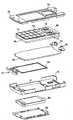
图3是内置于操作部侧框体部2的部件的分解立体图。FIG. 3 is an exploded perspective view of components built into the operation portion
图4是内置于显示部侧框体部3的部件的分解立体图。FIG. 4 is an exploded perspective view of components built into the display unit side frame portion 3 .
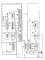
图5是表示本发明涉及的便携电话装置1的功能的框图。FIG. 5 is a block diagram showing the functions of the mobile phone device 1 according to the present invention.
图6是表示本发明涉及的便携电话装置1所具备的磁场天线53的第1结构的图。FIG. 6 is a diagram showing a first configuration of the
图7是表示本发明涉及的便携电话装置1所具备的磁场天线53的第2结构的图。FIG. 7 is a diagram showing a second structure of the
图8是表示作为本发明涉及的与主机装置进行通信的便携电话装置的第1实施方式的便携电话装置1的内观立体图的图。8 is a diagram showing an internal perspective view of a mobile phone device 1 as a first embodiment of the mobile phone device that communicates with a host device according to the present invention.
图9是利用A-A线剖切图8所示的便携电话装置1时的剖视图。FIG. 9 is a cross-sectional view of the mobile phone device 1 shown in FIG. 8 taken along line A-A.
具体实施方式Detailed ways
以下,参照附图来说明用于实施本发明的方式。而且,以下虽然对作为通信设备一例的便携电话机进行说明,但本发明并不限定于此,也可适用于PHS(Personal Handy Phone System:注册商标)、PDA(PersonalDigital Assistant:个人数字助理)、便携式导航装置、笔记本电脑等具备天线的其他的通信设备。Hereinafter, modes for implementing the present invention will be described with reference to the drawings. In addition, although a mobile phone as an example of a communication device will be described below, the present invention is not limited thereto, and can also be applied to PHS (Personal Handy Phone System: registered trademark), PDA (Personal Digital Assistant: Personal Digital Assistant), Other communication devices equipped with antennas, such as portable navigation devices and notebook computers.
<第1实施方式><First Embodiment>
图1是表示作为与主机装置进行通信的本发明涉及的通信设备一例的便携电话装置1的外观立体图。此外,图2表示将便携电话装置1折叠后的状态的立体图。FIG. 1 is an external perspective view showing a mobile phone device 1 as an example of a communication device according to the present invention that communicates with a host device. In addition, FIG. 2 shows a perspective view of a folded state of the mobile phone device 1 .
如图1及图2所示,便携电话装置1具备操作部侧框体部2(第二框体)和显示部侧框体部3(第一框体),操作部侧框体部2的表面由前面板2a、前壳体2b、后壳体2c和未图示的后面板2d构成,显示部侧框体部3的表面由前面板3a、前壳体3b、后壳体3c和后面板3d构成。As shown in FIGS. 1 and 2 , the mobile phone device 1 is provided with an operation unit side housing 2 (second housing) and a display unit side housing 3 (first housing). The surface is composed of a
操作部侧框体部2构成为操作按钮群11和输入便携电话装置1的使用者在通话时发出的声音的声音输入部12露出在前面板2a的表面。此外,操作按钮群11包括:用于使各种设定或电话簿功能或邮件功能等各种功能工作的功能设定操作按钮13、用于输入电话号的数字或邮件等文字等的输入操作按钮14、进行各种操作中的确定或滚动等的确定操作按钮15。此外,在操作部侧框体部2的侧面设有盖,该盖覆盖用于与外部设备(例如主机装置)进行通信的接口。The operation part side
此外,显示部侧框体部3构成为前面板3a使用于显示各种信息的显示器21、输出通话的对方侧的声音的接收器22露出。In addition, the display unit side housing unit 3 is configured such that a
此外,如图1所示,操作部侧框体部2的上端部与显示部侧框体部3的下端部经由铰链机构4(连接部)来连接。此外,通过使经由铰链机构4连接的操作部侧框体部2与显示部侧框体部3相对运动,便携电话装置1能够形成为操作部侧框体部2的表面与显示部侧框体部3的表面相互相对折叠的状态(相互重合的第1状态,关闭状态),或者操作部侧框体部2的表面与显示部侧框体部3的表面向外部露出而相互打开的状态(重合程度比折叠的状态小的第2状态,开启状态)。而且,在本实施方式中,说明了由铰链机构4形成的折叠式的便携电话装置1,但也可不是折叠式,而是由使两框体2、3重合的状态使一方的框体向一方向滑动的滑动式、或者以沿着重合方向的轴线为中心而使一方的框体旋转的旋转式、或者两框体2、3经由2轴铰链来连接。In addition, as shown in FIG. 1 , the upper end portion of the operation portion
如图2所示,操作部侧框体部2在一侧的侧面上具备:分配有规定的功能的侧键30、进行外部存储器的插入及取出的接口用的盖31。此外,显示部侧框体部3在一侧的侧面上具备详细后述的滑动键32。此外,在显示部侧框体部3的后面板3d表面上,对被摄体进行撮像的摄像机33和向被摄体照射光的灯34露出地形成。而且,摄像机33和灯34构成摄像机模块。As shown in FIG. 2 , the operation
此外,图3是内置在操作部侧框体部2内的部件的分解立体图。如图3所示,操作部侧框体部2具备:前面板2a、前壳体2b(本图中前面板2a与前壳体2b结合)、构成上述的操作按钮群11的键片40、柔性配线基板45、具备基准电位图案层及RF(Radio Frequency)模块等各种电子部件的印刷基板50(第二导电部)、铰链机构4a、4b、主天线51(第一天线)、磁场天线53(第二天线)、后壳体2c、保护充电电池60的后面板2d。In addition, FIG. 3 is an exploded perspective view of components built in the operation portion
此外,在操作部侧框体部2中,层叠配置有前壳体2b、键片40、印刷基板50、后壳体2c。此外,充电电池60由后面板2d的外侧能够插拔地收纳。Moreover, in the operation part
如图3所示,前壳体2b与后壳体2c以相互的凹状的内侧面相对的方式配置,且以相互的外周缘重合的方式而结合。此外,在前壳体2b与后壳体2c之间夹着键片40、印刷基板50而将它们内置。也就是说,在印刷基板50的上表面层叠配置有键片40。As shown in FIG. 3 , the
柔性配线基板45形成为如下构造:在前面板2a侧的面上具有多个键开关,且各个键开关具有弯曲成碗状而立体形成的金属板的金属圆盖。金属圆盖在其碗状的顶点被按压时,金属圆盖与印刷在柔性配线基板45的表面上的未图示的电路中形成的开关端子接触,从而电导通。而且,柔性配线基板45在多个绝缘薄膜之间夹入有配线。The
此外,印刷基板50上配置有未图示的各种电子部件。各种电子部件通过规定的组合而形成多个电路模块。例如形成包括无线电路、电源电路、数字电路等的各种电路模块。In addition, various electronic components not shown are arranged on the printed
在前面板2a上,在将便携电话装置1折叠后的状态下与显示部侧框体部3的显示器21相对的内侧面上形成有多个键孔。形成在键片40上的功能设定操作按钮13、输入操作按钮14及确定操作按钮15的按压面分别从多个键孔露出。通过按下构成该露出的操作按钮群11的功能设定操作按钮13、输入操作按钮14及确定操作按钮15的按压面,各自对应的键开关的金属圆盖(碗状)的顶点被按压,从而与开关端子接触而电导通。A plurality of keyholes are formed on the
在后壳体2c的一端侧配置有收纳于基台的主天线51。也就是说,主天线51配置在便携电话装置1的一端侧。具体来说,主天线51配置在便携电话装置1的与铰链机构4侧相反的端部侧。此外,主天线51以带状的金属板来形成。The
主天线51(第一天线)是进行涉及通话或电子邮件等电磁波的发送接收的天线,且从印刷基板50经由未图示的供电端子供电而构成。由此,主天线51从印刷基板50经由供电端子来供电,并且与设置在印刷基板50上的RF模块等连接。而且,在本实施方式中,将主天线51的位置设置在后壳体2c的一端,但也可配置在操作部侧框体部2的内部的任意部位。此外,也可将主天线51的位置配置在显示部侧框体部3的内部的任意部位。The main antenna 51 (first antenna) is an antenna for transmitting and receiving electromagnetic waves such as telephone calls and e-mails, and is configured to be powered from the printed
图4是内置在显示部侧框体部3中的部件的分解立体图。如图4所示,显示部侧框体部3具备:前面板3a、前壳体3b、铰链机构4、扬声器70a,70b、马达75、显示器21、与显示器21连接的印刷基板80(第一导电部)、后壳体3c和后面板3d。此外,在显示部侧框体部3中,前面板3a、前壳体3b、显示器21、印刷基板80、后壳体3c和后面板3d层叠配置。FIG. 4 is an exploded perspective view of components built into the display unit side frame 3 . As shown in FIG. 4 , the display portion side frame body portion 3 includes: a
如图4所示,前壳体3b与后壳体3c以相互的凹状的内侧面相对的方式来配置,且以相互的外周缘重合的方式结合。此外,在前壳体3b与后壳体3c之间夹着显示器21和印刷基板80而将它们内置。此外,扬声器70a、70b和马达75与印刷基板80连接。As shown in FIG. 4 , the
此外,图5是表示便携电话装置1的功能的功能框图。如图5所示,便携电话装置1具备:作为RFID(Radio Frequency Identification)部的第二通信部5、与外部的终端进行通信的第一通信部6、对利用第一通信部6通信的信息进行处理的处理部7。In addition, FIG. 5 is a functional block diagram showing the functions of the mobile phone device 1 . As shown in FIG. 5 , the mobile phone device 1 is provided with: a second communication unit 5 as an RFID (Radio Frequency Identification) unit, a first communication unit 6 for communicating with an external terminal, and an information communication unit using the first communication unit 6. Processing section 7 for processing.
<第二通信部5的结构><Structure of the second communication unit 5>
第二通信部5由上述的RFID部来构成,且具备RFID芯片9、利用第二使用频带(例如,13.56MHz)(第二频带)来与外部装置进行通信的磁场天线53、调整用的电容器54。The second communication unit 5 is composed of the above-mentioned RFID unit, and includes an RFID chip 9, a
磁场天线53例如具备由PET(polyethylene terephthalate)材料构成的片上多次卷绕成涡旋状的线圈,接收从外部装置发送的第二使用频带的信号。而且,磁场天线53也可通过卷绕导线来构成。The
RFID芯片9具备:基于由磁场天线53接收的信号所诱发的电力而生成规定的电压的电源电路55、相对于通过磁场天线53通信的信号进行调制处理或者解调处理等信号处理的RF电路56、进行规定的运算处理的CPU57、存储有规定的数据的存储器58。电源电路55例如由DC-DC逆变器来构成。此外,CPU57由信号线S而与后述的CPU71连接,将由第二通信部5处理后的信息经由信号线S向CPU71供给。The RFID chip 9 includes: a
在此,对于第二通信部5的动作进行说明。磁场天线53在相对于设置在外部的读写装置接近到规定距离时,接收从该读写装置发送的磁场(相对于第二使用频带即载波频率(例如,13.56MHz)调制)。而且,为了使第二使用频带的磁场经由磁场天线53向RF电路56供给,电容器54进行规定的调整(调谐)。Here, the operation of the second communication unit 5 will be described. The
此外,当由磁场天线53接收磁场时,利用电磁感应作用而发生电动势。电源电路55由根据电磁感应作用而发生的电动势而生成规定的电源电压,并向RF电路56、CPU57、存储器58供给。此外,RF电路56、CPU57、存储器58通过从电源电路55供给规定的电源电压而从停止状态变为启动状态。In addition, when a magnetic field is received by the
RF电路56相对于经由磁场天线53供给的第二使用频带的信号进行解调等信号处理,并将处理后的信号向CPU57供给。The
CPU57基于从RF电路56供给的信号向存储器58写入数据,或者从存储器58读出数据。在CPU57从存储器58读出数据的情况下,将该数据向RF电路56供给。RF电路56相对于从存储器58读出的数据进行调制等信号处理,并经由磁场天线53向外部的读写装置发送。The
此外,上述中,说明了第二通信部5作为不具有电源部的所谓被动型(Passive)的感应电磁场方式(电磁感应方式),但并不限定于此,也可是被动型的相互感应方式(电磁耦合方式)或者放射电磁场方式(电波方式),或者,也可是具有电源部的能动型(Active)。此外,作为第二通信部5的访问方式,说明了作为读写型的访问方式,但并不局限于此,也可是只读型或一次写入型等。In addition, in the above, the second communication unit 5 has been described as a so-called passive (Passive) induction electromagnetic field method (electromagnetic induction method) that does not have a power supply unit, but it is not limited thereto, and may be a passive mutual induction method ( electromagnetic coupling method) or a radiation electromagnetic field method (radio wave method), or an active type (Active) having a power supply unit may be used. In addition, the access method of the second communication unit 5 has been described as a read-write type, but it is not limited thereto, and may be a read-only type or a write-once type.
<第一通信部6的构成><Configuration of First Communication Unit 6 >
此外,如图5所示,第一通信部6具备:利用比第二使用频带高的频带即第一使用频带(第一频带)来与外部装置进行通信的主天线51、和包括RF电路、且进行调制处理或者解调处理等信号处理的通信处理部52。此外,第一通信部6从充电电池60接受电源的供给。In addition, as shown in FIG. 5 , the first communication unit 6 includes: a
主天线51利用第一使用频带(例如、800MHz)与外部装置进行通信。而且,在本实施方式中,作为第一使用频带设为800MHz,但也可是其以外的频带。此外,除了第一使用频带以外,主天线51也可是由能够与第三使用频带(例如、2GHz)对应的所谓的双频段对应型所形成的结构,进而,也可是通过能够与第四使用频带对应的多频段对应型来构成。The
通信处理部52对由主天线51接受的信号进行解调处理,并将处理后的信号向处理部7供给,并对从处理部7供给的信号进行调制处理,并经由主天线51向外部装置发送。The
<处理部7的构成><Configuration of Processing Unit 7>
此外,如图5所示,处理部7具备:操作按钮群11、声音输入部12、显示器21、接收器22、进行规定的运算处理的CPU71、存储有规定的数据的存储器72、进行规定的音处理的声音处理部73、进行规定的图像处理的图像处理部74、以一定周期振动的马达75、对被摄体进行拍摄的摄像机33、输出来电音等的扬声器70a、70b。此外,处理部7从充电电池60接受电源的供给。而且,如图5所示,便携电话装置1中,CPU57与CPU71通过信号线S连接,经由信号线S而由第二通信部5处理后的信息向CPU71供给,并根据需要进行处理。In addition, as shown in FIG. 5 , the processing unit 7 includes: an
本发明的目的之一是主动利用磁场天线53的高次谐振点,从而提高主天线51的天线增益。One of the purposes of the present invention is to actively use the high-order resonance point of the
在此,以下说明用于达到上述目的的具体的结构。而且,以下,以主天线51与磁场天线53配设在操作部侧框体部2来进行说明,但本发明并不限定于此,例如,主天线51与磁场天线53也可配设在显示部侧框体部3,也可使主天线51配设在操作部侧框体部2与显示部侧框体部3之一,磁场天线53配设在操作部侧框体部2和显示部侧框体部3的另一个。Here, a specific structure for achieving the above object will be described below. Moreover, in the following, the
<第1构成><1st composition>
便携电话装置1具有:经由铰链机构4内而与印刷基板80和印刷基板50电连接的信号线、配设在显示部侧框体部3及操作部侧框体部2的至少任一个,并且与印刷基板80或者印刷基板50电连接的主天线51(第一天线)。在显示部侧框体部3内配设有与印刷基板80电连接的金属部,且在显示部侧框体部3及操作部侧框体部2的至少任一方配设有在开启状态下与金属部或印刷基板50或者印刷基板80电容耦合的磁场天线53(第二天线)。此外,金属部例如相当于扬声器70a,70b或马达75等。而且,磁场天线53也可不经由金属部而与印刷基板80直接电容耦合。The mobile phone device 1 has: a signal line electrically connected to the printed
通过如此构成,在本发明中,在开启状态下,通过使金属部或印刷基板50或者印刷基板80与磁场天线53电容耦合,能够使显示部侧框体部3(第一框体)和操作部侧框体部2(第二框体)的高频的地线电平(グランドレベル)稳定化。由此,能够利用磁场天线53来实现主天线51的灵敏度提高,此外,能够提高框体内的设计上的自由度。With this configuration, in the present invention, in the open state, by capacitively coupling the metal portion or the printed
<第2构成><Second composition>
此外,在本发明中,优选主天线51构成为发送或者接收第一使用频带(第一频带)涉及的信号,且磁场天线53的高次的副次谐振点包含在第一使用频带中。In addition, in the present invention, it is preferable that the
通过如此构成,在本发明中,金属部或者印刷基板80与磁场天线53的电容耦合的程度提高,能够进一步提高开启状态下的主天线51的灵敏度。With such a configuration, in the present invention, the degree of capacitive coupling between the metal part or the printed
<第3构成><3rd composition>
此外,在本发明中,主天线51也可是构成为发送或者接收第一使用频带涉及的信号,且磁场天线53构成为发送或者接收高次的副次谐振点未包括在第一使用频带中的第二使用频带(第二频带)涉及的信号。此外,在该情况下,便携电话装置1优选具有对第二使用频带进行调整的调整机构。调整机构具有以使磁场天线53的高次的谐振点包含于第一使用频带的方式来调整第二使用频带的功能。而且,对于调整机构的具体的构成,如后述的<调整机构的具体的构成1>及<调整机构的具体的构成2>所示。In addition, in the present invention, the
通过如此构成,在本发明中,在某一条件下,利用由磁场天线53的高次谐振点进行的调整,金属部或者印刷基板80与磁场天线53的电容耦合的程度提高,能够实现主天线51的灵敏度提高。With such a configuration, in the present invention, under a certain condition, by adjusting the high-order resonance point of the
<第4构成><4th composition>
此外,如图5所示,便携电话装置1具有检测开启状态的检测部76(检测机构)。在此种构成中,当利用检测部76检测到开启状态时,调整机构以使磁场天线53的高次的谐振点包含于第一使用频带的方式来调整第二使用频带。Furthermore, as shown in FIG. 5 , the mobile phone device 1 has a detection unit 76 (detection means) that detects an open state. In such a configuration, when the ON state is detected by the
通过如此构成,在本发明中,在利用主天线51进行通信的可能性高的状态、即非常需要实现主天线51的灵敏度提高的开启状态下,金属部或者印刷基板80与磁场天线53的电容耦合的程度提高,能够实现主天线51的灵敏度提高。而且,在本发明中,在关闭状态下,由于不进行第二使用频带的调整,因此能够降低由于调整机构进行的磁场天线53的调整所导致的磁场天线53的劣化。With such a configuration, in the present invention, the capacitance between the metal part or the printed
<第5构成><The 5th composition>
此外,如图5所示,便携电话装置1具有检测关闭状态的检测部76。在此种构成中,当由检测部76检测到关闭状态时,调整机构抑制所述调整。Furthermore, as shown in FIG. 5 , the mobile phone device 1 has a
通过如此构成,在本发明的<第4构成>中,当处在开启状态对第二使用频带进行调整时,状态从开启状态向关闭状态变化时,抑制该调整。因此,能够降低由于调整机构进行的磁场天线53的调整导致的磁场天线53的劣化。With such a configuration, in the <4th configuration> of the present invention, when the second use frequency band is adjusted in the ON state, the adjustment is suppressed when the state changes from the ON state to the OFF state. Therefore, it is possible to reduce deterioration of the
<第6构成><Sixth composition>
此外,便携电话装置1具有通信处理部52(第一控制机构),该通信处理部52基于由主天线51发送或者接收的第一使用频带所涉及的信号,进行第一规定控制(例如由主天线51进行通话或数据通信时的通信控制)(参照图5)。在此种构成中,当由通信处理部52进行第一规定控制时,调整机构以使磁场天线53的高次的谐振点包含于第一使用频带的方式来对第二使用频带进行调整。In addition, the mobile phone device 1 has a communication processing unit 52 (first control means) that performs first predetermined control (for example, by the main communication control when the
通过如此构成,在本发明中,在非常需要实现主天线51的灵敏度提高的状态(在由通信处理部52进行第一规定控制的状态)下,金属部或者印刷基板80与磁场天线53的电容耦合的程度提高,能够实现主天线51的灵敏度提高。With such a configuration, in the present invention, in a state where it is extremely necessary to improve the sensitivity of the main antenna 51 (in a state where the first predetermined control is performed by the communication processing unit 52), the capacitance between the metal part or the printed
<第7构成><7th composition>
此外,当由通信处理部52抑制第一规定控制时,调整机构抑制所述调整,即优选不进行调整。In addition, when the first predetermined control is suppressed by the
通过如此构成,在本发明的<第6构成>中,当调整第二使用频带时,在变为不太需要实现主天线51的灵敏度提高的状态(抑制由通信处理部52进行的第一规定控制的状态)的情况下,抑制由调整机构进行的调整。因此,能够降低由于调整机构进行的磁场天线53的调整而导致的磁场天线53的劣化。With such a configuration, in the <sixth configuration> of the present invention, when adjusting the second frequency band to be used, it becomes less necessary to increase the sensitivity of the main antenna 51 (suppressing the first regulation by the communication processing unit 52). In the case of the state of control), the adjustment by the adjustment mechanism is suppressed. Therefore, it is possible to reduce deterioration of the
<第8构成><Eighth composition>
此外,如图5所示,便携电话装置1具有强度测定部78(第一强度测定机构),该强度测定部78对由主天线51发送或者接收的第一使用频带所涉及的信号的强度进行测定。在此种构成中,当由强度测定部78测定到规定值以上的值的强度时,调整机构以使磁场天线53的高次的谐振点包含于第一使用频带的方式来调整第二使用频带。In addition, as shown in FIG. 5 , the mobile phone device 1 has an intensity measuring unit 78 (first intensity measuring means) that measures the intensity of a signal related to the first frequency band that is transmitted or received by the
通过如此地构成,在本发明中,在非常需要实现主天线51的灵敏度提高的状态(由强度测定部78测定到规定值以上的值的强度的状态,且使用主天线51来通信的可能性高的状态)下,金属部或者印刷基板80与磁场天线53的电容耦合的程度提高,能够实现主天线51的灵敏度提高。With such a configuration, in the present invention, it is very necessary to realize the state in which the sensitivity of the
<第9构成><9th composition>
此外,当由强度测定部78测定到强度比规定值小的值时,调整机构抑制所述调整,即优选不进行调整。In addition, when a value smaller than a predetermined value is measured by the
通过如此构成,在本发明的<第8构成>中,当调整第二使用频带时,在变为不太需要实现主天线51的灵敏度提高的状态(由强度测定部78测定到强度比规定值小的值的状态,且使用主天线51进行通信的可能性低的状态)下,抑制调整。从而,能够降低由于调整机构进行的磁场天线53的调整所导致的磁场天线53的劣化。With such a configuration, in the <8th configuration> of the present invention, when adjusting the second frequency band to be used, it becomes less necessary to realize the improvement of the sensitivity of the main antenna 51 (measured by the
<第10构成><The 10th composition>
便携电话装置1具有强度测定部78,该强度测定部78对由主天线51发送或者接收的第一使用频带涉及的信号的强度进行测定。在此种构成中,当由强度测定部78测定到比规定值小的值的强度时,调整机构以使磁场天线53的高次的谐振点包含于第一使用频带的方式来调整第二使用频带。The mobile phone device 1 has a
通过如此构成,在本发明中,例如,当主天线51的电波状況弱时,调整磁场天线53的高次的谐振点使其包含于第一使用频带,从而金属部或者印刷基板80与磁场天线53的电容耦合的程度提高,能够提高主天线51的灵敏度。With such a configuration, in the present invention, for example, when the radio wave condition of the
<第11构成><Eleventh Composition>
当由强度测定部78测定到规定值以上的值的强度时,调整机构抑制所述调整,即、优选不进行调整。When the
通过如此构成,在本发明的<第10构成>中,当调整第二使用频带时,当主天线51的灵敏度变为良好的状态下,抑制该调整,因此能够抑制无用的消耗电力。此外,能够降低由于调整机构进行的磁场天线53的调整而导致的磁场天线53的劣化。With such a configuration, in the <10th configuration> of the present invention, when the sensitivity of the
<第12构成><The 12th composition>
具有RFID芯片9(第二控制机构),其进行基于由磁场天线53发送或者接收的第二使用频带涉及的信号的第二规定控制(例如,由磁场天线53进行通信时的通信控制)。在此种构成中,在不进行由RFID芯片9进行的第二规定控制的状态下,调整机构以使磁场天线53的高次的谐振点包含于第一使用频带的方式来调整第二使用频带。There is an RFID chip 9 (second control means) that performs second predetermined control based on a signal related to the second frequency band that is transmitted or received by the magnetic field antenna 53 (for example, communication control during communication by the magnetic field antenna 53 ). In such a configuration, in a state where the second predetermined control by the RFID chip 9 is not performed, the adjustment mechanism adjusts the second usable frequency band so that the high-order resonance point of the
通过如此构成,在不太需要实现磁场天线53的灵敏度提高的状态(抑制了由RFID芯片9进行的第二规定控制的状态,例如不使用RFID芯片9的状态)下,进行该调整。从而,在不太需要实现磁场天线53的灵敏度提高的状态下,由调整机构进行调整,因此金属部或者印刷基板80与磁场天线53的电容耦合的程度提高,能够实现主天线51的灵敏度提高。With this configuration, the adjustment is performed in a state where it is less necessary to increase the sensitivity of the magnetic field antenna 53 (a state in which the second predetermined control by the RFID chip 9 is suppressed, for example, a state in which the RFID chip 9 is not used). Therefore, in a state where it is not necessary to increase the sensitivity of the
<第13构成><The 13th composition>
在不进行由RFID芯片9进行的第二规定控制的状态下,调整机构抑制所述调整、即、优选不进行调整。In a state where the second predetermined control by the RFID chip 9 is not performed, the adjustment mechanism suppresses the adjustment, that is, preferably does not perform the adjustment.
通过如此构成,本发明的<第12构成>中,当调整第二使用频带时,在变为非常需要实现磁场天线53的灵敏度提高的状态(由RFID芯片9进行了第二规定控制的状态)的情况下,抑制该调整。从而,能够降低由于调整机构进行的磁场天线53的调整导致的磁场天线53的劣化。With such a configuration, in <the twelfth configuration> of the present invention, when adjusting the second frequency band to be used, it is very necessary to realize the improvement of the sensitivity of the magnetic field antenna 53 (the state in which the second predetermined control is performed by the RFID chip 9) In the case of , suppress this adjustment. Accordingly, it is possible to reduce deterioration of the
<第14构成><The 14th composition>
此外,如图5所示,便携电话装置1具有强度测定部78(第二强度测定机构),该强度测定部78对由磁场天线53发送或者接收的第二使用频带涉及的信号的强度进行测定。在此种构成中,当由强度测定部78测定到比规定值小的值的强度时,调整机构以使磁场天线53的高次的谐振点包含于第一使用频带的方式来调整第二使用频带。而且,本实施例中,强度测定部78测定由主天线51进行的第一使用频带涉及的信号的强度,并测定由磁场天线53进行的第二使用频带涉及的信号的强度,但并不限定于此,也可分别专用设置。In addition, as shown in FIG. 5, the mobile phone device 1 has an intensity measuring unit 78 (second intensity measuring mechanism) that measures the intensity of a signal related to the second use frequency band transmitted or received by the
通过如此构成,在本发明中,在不太需要实现磁场天线53的灵敏度提高的状态(例如,不进行基于磁场天线53的磁场通信的状态)下,金属部或者印刷基板80与磁场天线53的电容耦合的程度提高,能够优先实现主天线51的灵敏度提高。With such a configuration, in the present invention, in a state where it is not necessary to improve the sensitivity of the magnetic field antenna 53 (for example, a state where magnetic field communication by the
<第15构成><The 15th composition>
当由强度测定部78测定到规定值以上的值的强度时,调整机构抑制所述调整,即,优选不进行调整。When the
通过如此构成,在本发明的<第14构成>中,当调整第二使用频带时,在利用磁场天线53进行磁场通信的状态中,抑制该调整。从而,能够降低由调整机构进行的磁场天线53的调整所导致的磁场天线53的劣化。With such a configuration, in the <fourteenth configuration> of the present invention, when adjusting the second frequency band to be used, the adjustment is suppressed in a state where magnetic field communication is performed using the
<第16构成><The 16th composition>
此外,如图5所示,便携电话装置1具有强度测定部78,该强度测定部78对由磁场天线53发送或者接收的第二使用频带涉及的信号的强度进行测定。在此种构成中,当由强度测定部78测定到比规定值大的值的强度时,调整机构以使磁场天线53的高次的谐振点包含于第一使用频带的方式来调整第二使用频带。Furthermore, as shown in FIG. 5 , the mobile phone device 1 has an
通过如此构成,在本发明中,当磁场天线53的灵敏度在良好的状态下,积极地由调整机构进行调整。由此,金属部或者印刷基板80与磁场天线53的电容耦合的程度提高,能够将主天线51的灵敏度形成为良好的状态。With such a configuration, in the present invention, when the sensitivity of the
<第17构成><The 17th composition>
当由强度测定部78测定到规定值以下的值的强度时,调整机构抑制所述调整,即、优选不进行调整。When the
通过如此构成,在本发明的<第16的构成>中,当调整第二使用频带时,在由强度测定部78测定到规定值以下的强度,即、由磁场天线53进行磁场通信的必要性降低的情况下,抑制该调整,因此能够抑制主天线51的灵敏度劣化。With such a configuration, in the <sixteenth configuration> of the present invention, when adjusting the second frequency band for use, the
<第18构成><Eighteenth Composition>
主天线51与磁场天线53优选配设在不同的框体内。通过如此构成,能够在物理上使主天线51与磁场天线53的距离隔开,能够避免由于主天线51与磁场天线53接近而产生的不利情况。The
<调整机构的具体的构成1><Concrete constitution 1 of adjustment mechanism>
以下,对将磁场天线53的高次谐振点移动到主天线51的使用频带的调整机构的具体的构成进行说明。Hereinafter, a specific configuration of an adjustment mechanism for moving the high-order resonance point of the
如图6所示,便携电话装置1中,为了调整主天线51的频率特性,在一定条件下,通过开关来改变磁场天线53的天线图案的连接路径,形成为能够适当变更磁场天线53的电感值的结构。As shown in FIG. 6, in the mobile phone device 1, in order to adjust the frequency characteristics of the
磁场天线53在一方侧通过使第一开关部81、第二开关部82、集总常数电路83(调整机构)附加于而构成为能够选择第一路径和第二路径。The
第一开关部81包括:端子A1、端子B1、端子C1,第二开关部82包括:端子A2、端子B2、端子C2。The
集总常数电路83例如由线圈或并列谐振电路等相位旋转元件来构成,一端侧与第一开关部81的端子C1连接,另一端侧与第二开关部82的端子C2连接。而且,在本实施例中,附加了集总常数电路83,但只要能够改变电感值,也可是其他的构成要素,例如,也可附加铁素体(フエライト)等结构。The lumped constant circuit 83 is constituted by, for example, a phase rotation element such as a coil or a parallel resonant circuit, and one end thereof is connected to the terminal C1 of the
CPU71(控制部)在一定条件下控制第一开关部81和第二开关部82,并使端子A1和端子B 1导通,并且使端子A2和端子B2导通,由此构成第一路径。另一方面,CPU71使端子A1和端子C1导通,且使端子A2和端子C2导通,由此构成经由集总常数电路83连接的第二路径。The CPU 71 (control unit) controls the
在此,第一路径是第二通信部5中通信品质最好且通信电力效率最好的路径。此外,第二路径是经由集总常数电路83的路径,且在该状态中,改变磁场天线53的电感值,以由磁场天线53所形成的高次谐振点与主天线51的使用频带重合的方式构成。从而,在选择第二路径的情况下,能够提高由磁场天线53的高次谐振点形成的主天线51的增益。而且,即使在选择第二路径的情况下,磁场天线53也位于能够由第二使用频带与外部装置进行通信的频谱(スペツク)的范围内。Here, the first path is the path with the best communication quality and the best communication power efficiency in the second communication unit 5 . In addition, the second path is a path via the lumped constant circuit 83, and in this state, the inductance value of the
而且,在图6中,利用第一开关部81、第二开关部82、集总常数电路83构成的第二路径作为仅附加在构成磁场天线53的一部分的线上来表示,但并不限于此,也可是在整个线上附加第二路径的结构。Moreover, in FIG. 6, the second path constituted by the
<调整机构的具体的构成2><
此外,便携电话装置1也可是上述结构(图6)以外的结构,例如,如图7所示,在构成磁场天线53的线的规定的位置分别设置第一开关部81及第二开关部82。而且,在一定条件下,CPU71控制第一开关部81和第二开关部82,并使端子A1与端子B1导通,且使端子A2与端子B2导通,由此构成第一路径。另一方面,CPU71控制第一开关部81和第二开关部82,并使端子A1与端子C1导通,且使端子A2与端子C2导通,由此构成第二路径。如此,也可是通过基于第一路径的情况和基于第二路径的情况,改变磁场天线53的元件长度(电感值)的结构。In addition, the mobile phone device 1 may also have a structure other than the above-mentioned structure (FIG. 6). For example, as shown in FIG. . Also, under certain conditions, the CPU 71 controls the
根据此种构成,当选择第一路径时,能够良好地进行由磁场天线53进行的通信。此外,当选择第二路径时,磁场天线53的高次谐振点与主天线51的使用频带重合。因此,能够提高主天线51的增益。According to such a configuration, when the first path is selected, communication by the
<磁场天线53与金属部的配置关系><Arrangement Relationship Between
在此,图8是表示第1实施方式涉及的便携电话装置1的第1内观立体图的图。如图8所示,在操作部侧框体部2的后壳体2c上配置有印刷基板50,在显示部侧框体部3的后壳体3c上配置有印刷基板80和显示器21。Here, FIG. 8 is a diagram showing a first internal perspective view of the mobile phone device 1 according to the first embodiment. As shown in FIG. 8 , printed
在操作部侧框体部2的后壳体2c与印刷基板50之间配置有用于接收电波的主天线51。在显示部侧框体部3的后壳体3c与印刷基板80之间配置有用于发出受话声音的接收器22。此外,在与显示部侧框体部3的接收器22相反侧的后壳体3c与印刷基板80之间配置有具有金属等导电部并且与印刷基板80电连接的扬声器70a、70b(金属部)。A
此外,在操作部侧框体部2的印刷基板50上经由连接器95a连接同轴电缆90的一端,该同轴电缆90插通铰链机构4间并且由多个信号线和屏蔽线构成。显示部侧框体部3的印刷基板80经由连接器95b连接同轴电缆90的另一端。此外,在与配置于操作部侧框体部2的主天线51的相反侧的一端,构成图3所示的铰链机构4a的金属铰链4c(金属部)配置在与扬声器70a、70b相对的部位。金属铰链4c与印刷基板50电连接。而且,金属铰链4c也可使用在由塑料或树脂等构成的非导电性的铰链的内侧表面实施金属蒸镀的铰链(拟似的金属铰链)。Also, one end of a coaxial cable 90 is connected to the printed
以下,参照图9,对本实施方式的便携电话装置1中的特征性的作用效果进行说明。如图9所示,在磁场天线53、金属铰链4c和扬声器70a之间形成电容耦合。从主机装置经由空中到来的电波的到来波W由设置在便携电话装置1中主天线51谐振,并诱发高频电流,形成电力线101。因此,由到来波W诱发的高频电流从主天线51向印刷基板50-磁场天线53-扬声器70a、70b-印刷基板80传递,形成电高频地线(グランド)。图9中,高频电流W1、W2、W3、W4、W5表示此时的概略的状况。Hereinafter, the characteristic functions and effects of the mobile phone device 1 according to the present embodiment will be described with reference to FIG. 9 . As shown in FIG. 9, capacitive coupling is formed between the
根据此种构成,在本发明中,能够不阻碍设计上的自由而提高主天线51的增益。According to such a configuration, in the present invention, the gain of the
此外,在上述的实施例中,以配置在显示部侧框体部3的金属部(扬声器70a、70b等)、与配置在操作部侧框体部2的磁场天线53直接进行电容耦合的情况进行了说明,但并不限定于此。也可是金属部与磁场天线53间接进行电容耦合的构成(例如,磁场天线53与构成铰链机构4的金属部进行电容耦合,且构成铰链机构4的金属部与配置在显示部侧框体部3的金属部(扬声器70a、70b等)进行电容耦合的构成)。In addition, in the above-mentioned embodiment, the metal parts (
【符号的说明】【Description of symbols】
1 便携电话装置1 portable telephone device
2 操作部侧框体部2 Operation side frame body
2a 前面板2a Front panel
2b 前壳体2b Front housing
2c 后壳体2c rear case
2d 后面板2d back panel
3 显示部侧框体部3 Display side frame body
3c 后壳体3c rear case
3a 前面板3a Front panel
3b 前壳体3b Front housing
3c 后壳体3c rear case
3d 后面板3d back panel
4 铰链机构4 hinge mechanism
4a 铰链机构4a Hinge mechanism
4b 铰链机构4b Hinge mechanism
4c 金属铰链4c metal hinge
50 印刷基板50 printed substrates
55 天线元件55 antenna elements
56 近距离通信用天线56 Antennas for short-range communication
70a,70b 扬声器70a, 70b speakers
75 马达75 motor
80 印刷基板80 printed substrates
Claims (18)
Translated fromChineseApplications Claiming Priority (3)
| Application Number | Priority Date | Filing Date | Title |
|---|---|---|---|
| JP2008139942AJP5150369B2 (en) | 2008-05-28 | 2008-05-28 | Communication equipment |
| JP2008-139942 | 2008-05-28 | ||
| PCT/JP2009/059790WO2009145264A1 (en) | 2008-05-28 | 2009-05-28 | Communication device |
Publications (2)
| Publication Number | Publication Date |
|---|---|
| CN102037604A CN102037604A (en) | 2011-04-27 |
| CN102037604Btrue CN102037604B (en) | 2013-08-28 |
Family
ID=41377134
Family Applications (1)
| Application Number | Title | Priority Date | Filing Date |
|---|---|---|---|
| CN2009801182644AExpired - Fee RelatedCN102037604B (en) | 2008-05-28 | 2009-05-28 | Communication device |
Country Status (5)
| Country | Link |
|---|---|
| US (1) | US8494601B2 (en) |
| JP (1) | JP5150369B2 (en) |
| KR (1) | KR101176096B1 (en) |
| CN (1) | CN102037604B (en) |
| WO (1) | WO2009145264A1 (en) |
Families Citing this family (11)
| Publication number | Priority date | Publication date | Assignee | Title |
|---|---|---|---|---|
| JP5602484B2 (en)* | 2010-04-26 | 2014-10-08 | 京セラ株式会社 | Portable electronic devices |
| JP5619565B2 (en)* | 2010-10-27 | 2014-11-05 | 京セラ株式会社 | Communication device |
| US9166279B2 (en) | 2011-03-07 | 2015-10-20 | Apple Inc. | Tunable antenna system with receiver diversity |
| US9246221B2 (en) | 2011-03-07 | 2016-01-26 | Apple Inc. | Tunable loop antennas |
| EP2562868A1 (en)* | 2011-08-22 | 2013-02-27 | Laird Technologies AB | A multiple-turn loop antenna arrangement and a portable radio communication device comprising such an arrangement |
| US9350069B2 (en) | 2012-01-04 | 2016-05-24 | Apple Inc. | Antenna with switchable inductor low-band tuning |
| KR102086708B1 (en)* | 2013-03-13 | 2020-03-09 | 삼성전자 주식회사 | Electronic device having audio output module and housing therefor |
| US10122182B2 (en) | 2015-02-27 | 2018-11-06 | Qualcomm Incorporated | Multi-turn coil on metal backplate |
| KR102164704B1 (en) | 2015-11-13 | 2020-10-12 | 삼성전자주식회사 | Electronic device with metal frame antenna |
| CN113972496B (en) | 2019-05-13 | 2022-09-09 | 华为技术有限公司 | Electronic equipment |
| CN111158232B (en)* | 2019-06-13 | 2023-12-22 | 广东小天才科技有限公司 | Intelligent host, multi-antenna line switching method and intelligent watch |
Citations (4)
| Publication number | Priority date | Publication date | Assignee | Title |
|---|---|---|---|---|
| CN1392673A (en)* | 2001-06-13 | 2003-01-22 | 株式会社东芝 | Radio module and communication device having said radio module |
| CN1703895A (en)* | 2002-10-09 | 2005-11-30 | 松下电器产业株式会社 | Communication terminal |
| JP2008085988A (en)* | 2006-08-31 | 2008-04-10 | Casio Hitachi Mobile Communications Co Ltd | Antenna and portable electronic device |
| JP2008109506A (en)* | 2006-10-26 | 2008-05-08 | Sanyo Electric Co Ltd | Portable telephone |
Family Cites Families (9)
| Publication number | Priority date | Publication date | Assignee | Title |
|---|---|---|---|---|
| JP3551122B2 (en)* | 2000-04-07 | 2004-08-04 | 日本電気株式会社 | Mobile phone equipment |
| JP2004096341A (en)* | 2002-08-30 | 2004-03-25 | Fujitsu Ltd | Antenna device including inverted F-type antenna with variable resonance frequency |
| JP3800331B2 (en)* | 2002-10-22 | 2006-07-26 | ソニー株式会社 | Wireless communication circuit, wireless communication terminal and method, recording medium, and program |
| US7132946B2 (en)* | 2004-04-08 | 2006-11-07 | 3M Innovative Properties Company | Variable frequency radio frequency identification (RFID) tags |
| JP4649183B2 (en)* | 2004-11-30 | 2011-03-09 | 株式会社東芝 | Wireless communication terminal |
| JP4167649B2 (en)* | 2004-12-03 | 2008-10-15 | 埼玉日本電気株式会社 | Folding type mobile radio telephone with built-in non-contact IC card function |
| US20090033566A1 (en)* | 2005-03-30 | 2009-02-05 | Matsushita Electric Industrial Co., Ltd. | Folding type mobile radio |
| JP4257349B2 (en)* | 2005-09-08 | 2009-04-22 | 株式会社カシオ日立モバイルコミュニケーションズ | Antenna device and wireless communication terminal |
| KR101232557B1 (en)* | 2006-09-28 | 2013-02-12 | 교세라 가부시키가이샤 | Mobile radio device |
- 2008
- 2008-05-28JPJP2008139942Apatent/JP5150369B2/ennot_activeExpired - Fee Related
- 2009
- 2009-05-28WOPCT/JP2009/059790patent/WO2009145264A1/enactiveApplication Filing
- 2009-05-28USUS12/994,489patent/US8494601B2/ennot_activeExpired - Fee Related
- 2009-05-28KRKR1020107026008Apatent/KR101176096B1/ennot_activeExpired - Fee Related
- 2009-05-28CNCN2009801182644Apatent/CN102037604B/ennot_activeExpired - Fee Related
Patent Citations (4)
| Publication number | Priority date | Publication date | Assignee | Title |
|---|---|---|---|---|
| CN1392673A (en)* | 2001-06-13 | 2003-01-22 | 株式会社东芝 | Radio module and communication device having said radio module |
| CN1703895A (en)* | 2002-10-09 | 2005-11-30 | 松下电器产业株式会社 | Communication terminal |
| JP2008085988A (en)* | 2006-08-31 | 2008-04-10 | Casio Hitachi Mobile Communications Co Ltd | Antenna and portable electronic device |
| JP2008109506A (en)* | 2006-10-26 | 2008-05-08 | Sanyo Electric Co Ltd | Portable telephone |
Non-Patent Citations (2)
| Title |
|---|
| JP特开2008085988A 2008.04.10 |
| JP特开2008109506A 2008.05.08 |
Also Published As
| Publication number | Publication date |
|---|---|
| CN102037604A (en) | 2011-04-27 |
| JP5150369B2 (en) | 2013-02-20 |
| JP2009290480A (en) | 2009-12-10 |
| US8494601B2 (en) | 2013-07-23 |
| WO2009145264A1 (en) | 2009-12-03 |
| KR20110002865A (en) | 2011-01-10 |
| KR101176096B1 (en) | 2012-08-22 |
| US20110130102A1 (en) | 2011-06-02 |
Similar Documents
| Publication | Publication Date | Title |
|---|---|---|
| CN102037604B (en) | Communication device | |
| US8219143B2 (en) | Mobile radio device | |
| JP4242780B2 (en) | Balanced multiband antenna device | |
| US7069043B2 (en) | Wireless communication device with two internal antennas | |
| CN1617458B (en) | Antenna system for communication device | |
| JPH0897617A (en) | Electronic system with rf circuit incorporated to movable housing element | |
| US7603150B2 (en) | Wireless communication terminal having an impedance matching circuit | |
| WO2006022381A1 (en) | Portable radio | |
| WO2005053181A1 (en) | Mobile communication device | |
| JP5117607B2 (en) | Portable radio | |
| US8138979B2 (en) | Portable wireless apparatus | |
| JP2003258522A (en) | Antenna device | |
| US8779982B2 (en) | System for reducing antenna gain deterioration | |
| JP2003258962A (en) | Folding type mobile radio terminal | |
| JP2008211598A (en) | Communication equipment | |
| WO2006043543A1 (en) | Noncontact communication antenna and portable mobile terminal | |
| JP5074281B2 (en) | Communication equipment | |
| JP2011135249A (en) | Mobile radio terminal | |
| JP4836850B2 (en) | Communication equipment |
Legal Events
| Date | Code | Title | Description |
|---|---|---|---|
| C06 | Publication | ||
| PB01 | Publication | ||
| C10 | Entry into substantive examination | ||
| SE01 | Entry into force of request for substantive examination | ||
| C14 | Grant of patent or utility model | ||
| GR01 | Patent grant | ||
| CF01 | Termination of patent right due to non-payment of annual fee | Granted publication date:20130828 Termination date:20190528 | |
| CF01 | Termination of patent right due to non-payment of annual fee |