CN102036703B - Veterinary syringe for multiple injections - Google Patents
Veterinary syringe for multiple injectionsDownload PDFInfo
- Publication number
- CN102036703B CN102036703BCN2009801149326ACN200980114932ACN102036703BCN 102036703 BCN102036703 BCN 102036703BCN 2009801149326 ACN2009801149326 ACN 2009801149326ACN 200980114932 ACN200980114932 ACN 200980114932ACN 102036703 BCN102036703 BCN 102036703B
- Authority
- CN
- China
- Prior art keywords
- syringe cartridge
- cartridge
- syringe
- applicator
- plunger
- Prior art date
- Legal status (The legal status is an assumption and is not a legal conclusion. Google has not performed a legal analysis and makes no representation as to the accuracy of the status listed.)
- Active
Links
Images


Classifications
- A—HUMAN NECESSITIES
- A61—MEDICAL OR VETERINARY SCIENCE; HYGIENE
- A61M—DEVICES FOR INTRODUCING MEDIA INTO, OR ONTO, THE BODY; DEVICES FOR TRANSDUCING BODY MEDIA OR FOR TAKING MEDIA FROM THE BODY; DEVICES FOR PRODUCING OR ENDING SLEEP OR STUPOR
- A61M5/00—Devices for bringing media into the body in a subcutaneous, intra-vascular or intramuscular way; Accessories therefor, e.g. filling or cleaning devices, arm-rests
- A61M5/178—Syringes
- A61M5/24—Ampoule syringes, i.e. syringes with needle for use in combination with replaceable ampoules or carpules, e.g. automatic
- A61M5/2422—Ampoule syringes, i.e. syringes with needle for use in combination with replaceable ampoules or carpules, e.g. automatic using emptying means to expel or eject media, e.g. pistons, deformation of the ampoule, or telescoping of the ampoule
- A61M5/2425—Ampoule syringes, i.e. syringes with needle for use in combination with replaceable ampoules or carpules, e.g. automatic using emptying means to expel or eject media, e.g. pistons, deformation of the ampoule, or telescoping of the ampoule by compression of deformable ampoule or carpule wall
- A—HUMAN NECESSITIES
- A61—MEDICAL OR VETERINARY SCIENCE; HYGIENE
- A61M—DEVICES FOR INTRODUCING MEDIA INTO, OR ONTO, THE BODY; DEVICES FOR TRANSDUCING BODY MEDIA OR FOR TAKING MEDIA FROM THE BODY; DEVICES FOR PRODUCING OR ENDING SLEEP OR STUPOR
- A61M5/00—Devices for bringing media into the body in a subcutaneous, intra-vascular or intramuscular way; Accessories therefor, e.g. filling or cleaning devices, arm-rests
- A61M5/178—Syringes
- A61M5/31—Details
- A61M5/32—Needles; Details of needles pertaining to their connection with syringe or hub; Accessories for bringing the needle into, or holding the needle on, the body; Devices for protection of needles
- A61M5/3202—Devices for protection of the needle before use, e.g. caps
- A61M5/3204—Needle cap remover, i.e. devices to dislodge protection cover from needle or needle hub, e.g. deshielding devices
- A—HUMAN NECESSITIES
- A61—MEDICAL OR VETERINARY SCIENCE; HYGIENE
- A61D—VETERINARY INSTRUMENTS, IMPLEMENTS, TOOLS, OR METHODS
- A61D17/00—Devices for indicating trouble during labour of animals ; Methods or instruments for detecting pregnancy-related states of animals
- A—HUMAN NECESSITIES
- A61—MEDICAL OR VETERINARY SCIENCE; HYGIENE
- A61M—DEVICES FOR INTRODUCING MEDIA INTO, OR ONTO, THE BODY; DEVICES FOR TRANSDUCING BODY MEDIA OR FOR TAKING MEDIA FROM THE BODY; DEVICES FOR PRODUCING OR ENDING SLEEP OR STUPOR
- A61M5/00—Devices for bringing media into the body in a subcutaneous, intra-vascular or intramuscular way; Accessories therefor, e.g. filling or cleaning devices, arm-rests
- A61M5/002—Packages specially adapted therefor, e.g. for syringes or needles, kits for diabetics
- A61M2005/005—Magazines with multiple ampoules directly inserted into an injection or infusion device, e.g. revolver-like magazines containing ampoules with or without needles
- A—HUMAN NECESSITIES
- A61—MEDICAL OR VETERINARY SCIENCE; HYGIENE
- A61M—DEVICES FOR INTRODUCING MEDIA INTO, OR ONTO, THE BODY; DEVICES FOR TRANSDUCING BODY MEDIA OR FOR TAKING MEDIA FROM THE BODY; DEVICES FOR PRODUCING OR ENDING SLEEP OR STUPOR
- A61M5/00—Devices for bringing media into the body in a subcutaneous, intra-vascular or intramuscular way; Accessories therefor, e.g. filling or cleaning devices, arm-rests
- A61M5/178—Syringes
- A61M5/24—Ampoule syringes, i.e. syringes with needle for use in combination with replaceable ampoules or carpules, e.g. automatic
- A61M2005/2403—Ampoule inserted into the ampoule holder
- A61M2005/2414—Ampoule inserted into the ampoule holder from the side
- A—HUMAN NECESSITIES
- A61—MEDICAL OR VETERINARY SCIENCE; HYGIENE
- A61M—DEVICES FOR INTRODUCING MEDIA INTO, OR ONTO, THE BODY; DEVICES FOR TRANSDUCING BODY MEDIA OR FOR TAKING MEDIA FROM THE BODY; DEVICES FOR PRODUCING OR ENDING SLEEP OR STUPOR
- A61M5/00—Devices for bringing media into the body in a subcutaneous, intra-vascular or intramuscular way; Accessories therefor, e.g. filling or cleaning devices, arm-rests
- A61M5/178—Syringes
- A61M5/24—Ampoule syringes, i.e. syringes with needle for use in combination with replaceable ampoules or carpules, e.g. automatic
- A61M2005/2481—Ampoule syringes, i.e. syringes with needle for use in combination with replaceable ampoules or carpules, e.g. automatic comprising means for biasing the ampoule out of the ampoule holder
- A—HUMAN NECESSITIES
- A61—MEDICAL OR VETERINARY SCIENCE; HYGIENE
- A61M—DEVICES FOR INTRODUCING MEDIA INTO, OR ONTO, THE BODY; DEVICES FOR TRANSDUCING BODY MEDIA OR FOR TAKING MEDIA FROM THE BODY; DEVICES FOR PRODUCING OR ENDING SLEEP OR STUPOR
- A61M5/00—Devices for bringing media into the body in a subcutaneous, intra-vascular or intramuscular way; Accessories therefor, e.g. filling or cleaning devices, arm-rests
- A61M5/178—Syringes
- A61M5/31—Details
- A61M5/315—Pistons; Piston-rods; Guiding, blocking or restricting the movement of the rod or piston; Appliances on the rod for facilitating dosing ; Dosing mechanisms
- A61M5/31511—Piston or piston-rod constructions, e.g. connection of piston with piston-rod
- A61M2005/31516—Piston or piston-rod constructions, e.g. connection of piston with piston-rod reducing dead-space in the syringe barrel after delivery
- A—HUMAN NECESSITIES
- A61—MEDICAL OR VETERINARY SCIENCE; HYGIENE
- A61M—DEVICES FOR INTRODUCING MEDIA INTO, OR ONTO, THE BODY; DEVICES FOR TRANSDUCING BODY MEDIA OR FOR TAKING MEDIA FROM THE BODY; DEVICES FOR PRODUCING OR ENDING SLEEP OR STUPOR
- A61M2250/00—Specially adapted for animals
- A—HUMAN NECESSITIES
- A61—MEDICAL OR VETERINARY SCIENCE; HYGIENE
- A61M—DEVICES FOR INTRODUCING MEDIA INTO, OR ONTO, THE BODY; DEVICES FOR TRANSDUCING BODY MEDIA OR FOR TAKING MEDIA FROM THE BODY; DEVICES FOR PRODUCING OR ENDING SLEEP OR STUPOR
- A61M5/00—Devices for bringing media into the body in a subcutaneous, intra-vascular or intramuscular way; Accessories therefor, e.g. filling or cleaning devices, arm-rests
- A61M5/178—Syringes
- A61M5/24—Ampoule syringes, i.e. syringes with needle for use in combination with replaceable ampoules or carpules, e.g. automatic
- A61M5/2455—Ampoule syringes, i.e. syringes with needle for use in combination with replaceable ampoules or carpules, e.g. automatic with sealing means to be broken or opened
- A61M5/2459—Ampoule syringes, i.e. syringes with needle for use in combination with replaceable ampoules or carpules, e.g. automatic with sealing means to be broken or opened upon internal pressure increase, e.g. pierced or burst
- A—HUMAN NECESSITIES
- A61—MEDICAL OR VETERINARY SCIENCE; HYGIENE
- A61M—DEVICES FOR INTRODUCING MEDIA INTO, OR ONTO, THE BODY; DEVICES FOR TRANSDUCING BODY MEDIA OR FOR TAKING MEDIA FROM THE BODY; DEVICES FOR PRODUCING OR ENDING SLEEP OR STUPOR
- A61M5/00—Devices for bringing media into the body in a subcutaneous, intra-vascular or intramuscular way; Accessories therefor, e.g. filling or cleaning devices, arm-rests
- A61M5/178—Syringes
- A61M5/31—Details
- A61M5/3129—Syringe barrels
- A—HUMAN NECESSITIES
- A61—MEDICAL OR VETERINARY SCIENCE; HYGIENE
- A61M—DEVICES FOR INTRODUCING MEDIA INTO, OR ONTO, THE BODY; DEVICES FOR TRANSDUCING BODY MEDIA OR FOR TAKING MEDIA FROM THE BODY; DEVICES FOR PRODUCING OR ENDING SLEEP OR STUPOR
- A61M5/00—Devices for bringing media into the body in a subcutaneous, intra-vascular or intramuscular way; Accessories therefor, e.g. filling or cleaning devices, arm-rests
- A61M5/178—Syringes
- A61M5/31—Details
- A61M5/315—Pistons; Piston-rods; Guiding, blocking or restricting the movement of the rod or piston; Appliances on the rod for facilitating dosing ; Dosing mechanisms
- A61M5/31511—Piston or piston-rod constructions, e.g. connection of piston with piston-rod
- A—HUMAN NECESSITIES
- A61—MEDICAL OR VETERINARY SCIENCE; HYGIENE
- A61M—DEVICES FOR INTRODUCING MEDIA INTO, OR ONTO, THE BODY; DEVICES FOR TRANSDUCING BODY MEDIA OR FOR TAKING MEDIA FROM THE BODY; DEVICES FOR PRODUCING OR ENDING SLEEP OR STUPOR
- A61M5/00—Devices for bringing media into the body in a subcutaneous, intra-vascular or intramuscular way; Accessories therefor, e.g. filling or cleaning devices, arm-rests
- A61M5/178—Syringes
- A61M5/31—Details
- A61M5/315—Pistons; Piston-rods; Guiding, blocking or restricting the movement of the rod or piston; Appliances on the rod for facilitating dosing ; Dosing mechanisms
- A61M5/31565—Administration mechanisms, i.e. constructional features, modes of administering a dose
- A61M5/31576—Constructional features or modes of drive mechanisms for piston rods
- A61M5/31578—Constructional features or modes of drive mechanisms for piston rods based on axial translation, i.e. components directly operatively associated and axially moved with plunger rod
- A61M5/3158—Constructional features or modes of drive mechanisms for piston rods based on axial translation, i.e. components directly operatively associated and axially moved with plunger rod performed by axially moving actuator operated by user, e.g. an injection button
Landscapes
- Health & Medical Sciences (AREA)
- Vascular Medicine (AREA)
- Engineering & Computer Science (AREA)
- Anesthesiology (AREA)
- Biomedical Technology (AREA)
- Heart & Thoracic Surgery (AREA)
- Hematology (AREA)
- Life Sciences & Earth Sciences (AREA)
- Animal Behavior & Ethology (AREA)
- General Health & Medical Sciences (AREA)
- Public Health (AREA)
- Veterinary Medicine (AREA)
- Infusion, Injection, And Reservoir Apparatuses (AREA)
- Coating Apparatus (AREA)
Abstract
Translated fromChinese
Description
Translated fromChinese技术领域technical field
本发明涉及用于多重注射的兽医注射器,即用于注射动物的注射器,特别是当多个动物必须注射时,就象在处理一大群或饲养的家畜时的情况。The present invention relates to veterinary injectors for multiple injections, ie injectors for injecting animals, especially when multiple animals have to be injected, as is the case when dealing with large herds or domestic animals.
背景技术Background technique
美国专利4020838描述了一种动物计量注射器(用于通过喷嘴向咽喉灌药,或者通过针头来用于注射)。它为枪的形状,具有与喷嘴成直角的把手。US Patent 4020838 describes an animal metering syringe (for throat irrigation through a nozzle, or through a needle for injection). It is in the shape of a gun with a handle at right angles to the nozzle.
美国专利6,554,161描述了一种多筒管分配装置。可互换的部件允许改变所提供的剂量。US Patent 6,554,161 describes a multiple cartridge dispensing device. Interchangeable parts allow changing the dose provided.
美国专利5,199,949描述一种多重药品注射器。它具有多个无菌的药盒,这些药盒包含保持在它的壳体内的胰岛素。该药盒被穿刺,流体流入存储器中,它能够通过针头组件而从该存储器分配。US Patent 5,199,949 describes a multiple drug syringe. It has sterile cartridges containing insulin held within its housing. The cartridge is pierced and fluid flows into the reservoir from which it can be dispensed through the needle assembly.
美国专利5,122,057描述了用于牙科计量供给药盒的装置-该药盒布置在装药孔中,并在糊状剂通过活塞的操作(该活塞的操作通过操作杆或螺杆作用来操作)而排出之前在注射器枪内保持就位。US Patent 5,122,057 describes a device for a dental metered-feed cartridge - the cartridge is placed in a charging hole and is expelled after the paste is discharged by the operation of a piston operated by rod or screw action Previously held in place within the syringe gun.
美国专利6,616,634表示了人机工程学的注射器,该注射器设计成在外科手术过程中降低疲劳和紧张。US Patent 6,616,634 shows an ergonomic syringe designed to reduce fatigue and strain during surgical procedures.
技术问题:technical problem:
通常用“干的”乳房内抗生素于来处理整个乳畜群。当前,抗生素通过非常基本的一次性注射器来给药。四个母牛乳房中的每一个都要处理,对于一群250头母牛,这需要1,000次剂量给药。通常的抱怨是现有的注射器握住很麻烦,很难挤压,并很难利用用户的手指,特别是当在大量处理的应用过程中重复使用时。The whole dairy herd is usually treated with "dry" intramammary antibiotics. Currently, antibiotics are administered through very basic disposable syringes. Each of the four udders is treated, which requires 1,000 doses for a herd of 250 cows. Common complaints are that existing syringes are cumbersome to hold, difficult to squeeze, and difficult to utilize with the user's fingers, especially when re-used during high-volume application.
对于普通的注射器,只有两个手指以及拇指或手掌可以用于施加力,以便分配药盒的内容物。而且,注射器的纵向轴线与由用户施加力的轴线平行对齐。这样,为了注射位于奶牛下面的乳房,给药者必须笨拙地控制他们的身体,以便试着使得注射器针头朝上,这已经证明很难和很费力。With a normal syringe, only two fingers and the thumb or palm can be used to apply force in order to dispense the contents of the cartridge. Also, the longitudinal axis of the syringe is aligned parallel to the axis of force applied by the user. Thus, in order to inject the udder below the cow, the administerer must awkwardly control their body in order to try to point the syringe needle upwards, which has proven difficult and strenuous.
传统注射器的另一问题是需要在类似位置注射多个乳头。目前,这需要用户一直人工更换用过的注射器、重新装载和重新定位,以便重新开始注射。还很难知道药盒的全部内容物在什么时候都已经分配。Another problem with conventional syringes is the need to inject multiple nipples in similar locations. Currently, this requires the user to manually replace the spent syringe, reload and reposition it all the time in order to restart the injection. It is also difficult to know when the entire contents of the kit have been dispensed.
在乳房内施药过程中,注射器喷嘴在分配过程中的可视性也很重要,用于视觉引导。由于上述问题,在施药过程中可能很难看见注射器喷嘴和引导它至正确位置。另一问题是在奶牛乳房下面的空间限制。一些乳房下垂非常低,直到地面,乳头也可能非常靠近动物的腿。普通的注射器并不非常紧凑,它们的庞大以及有限空间使得很难成功地操纵注射器至任意给定的乳头上。During intramammary administration, the visibility of the syringe nozzle during dispensing is also important for visual guidance. Due to the above problems, it can be difficult to see the syringe nozzle and guide it to the correct position during application. Another problem is the space constraints under the cow's udder. Some breasts droop very low to the ground, and the nipples may also be very close to the animal's legs. Common syringes are not very compact, their bulk and limited space make it difficult to successfully maneuver the syringe onto any given teat.
乳房内施药的还一重要方面是无菌。注射器必须保持无菌,以便防止污染乳头以及在一头奶牛的乳头和其它奶牛的乳头之间的交叉污染,用于使感染的危险最小。现有注射器的设计不能容易地在乳房内的施药过程中保持无菌环境。Another important aspect of intramammary administration is sterility. The syringe must be kept sterile in order to prevent contamination of the teat and cross-contamination between one cow's teat and another cow's teat for minimizing the risk of infection. Existing syringe designs do not readily maintain a sterile environment during intramammary administration.
因此,需要一种改进的装置,它更容易使用,不费力、可靠、紧凑、制造便宜和/或它使在施药过程中产生污染的危险最小化。Therefore, there is a need for an improved device that is easier to use, less labor intensive, reliable, compact, inexpensive to manufacture and/or which minimizes the risk of contamination during application.
在本说明书中,除非另外说明,当参考或介绍文件、报告或知识条目时,该参考或介绍并不是承认该文件、报告或知识条目或者它们的任意组合是在优先权日期可以由公众获得、由公众知道或者是公知常识的一部分,或者知道试图通过本说明书涉及的来解决任何问题。In this specification, unless otherwise stated, when a document, report or item of knowledge is referenced or introduced, such reference or introduction is not an admission that the document, report or item of knowledge, or any combination thereof, was available to the public, Known by the public or part of the common general knowledge, or known to attempt to solve any problem addressed by this specification.
发明目的purpose of invention
本发明的目的是提供一种改进的注射器,它改善了一些上述缺点和限制,或者至少向公众提供了有用的选择。It is an object of the present invention to provide an improved syringe which ameliorates some of the above-mentioned disadvantages and limitations, or at least provides the public with a useful choice.
发明内容Contents of the invention
在一个方面,本发明提供了一种注射器药盒施加器,用于从注射器药盒分配流体,该装置包括:施加器触发器,该施加器触发器可从伸出位置运动至退回位置;柱塞组件,该柱塞组件与施加器触发器相接,其中,施加器触发器从伸出位置至退回位置的运动导致柱塞组件从注射器药盒中驱动流体;以及注射器药盒保持组件,该注射器药盒保持组件用于可拆卸地接收在分配位置的注射器药盒。In one aspect, the present invention provides a syringe cartridge applicator for dispensing fluid from a syringe cartridge, the device comprising: an applicator trigger movable from an extended position to a retracted position; a plunger assembly interfaced with the applicator trigger, wherein movement of the applicator trigger from the extended position to the retracted position causes the plunger assembly to drive fluid from the syringe cartridge; and a syringe cartridge retaining assembly, the The syringe cartridge retention assembly is for removably receiving the syringe cartridge in a dispensing position.
优选地,注射器药盒分配装置包括引导组件,用于沿装载方向滑动地接收注射器药盒,该装载方向定向成基本垂直于注射器药盒的纵向轴线。Preferably, the syringe cartridge dispensing device comprises a guide assembly for slidingly receiving the syringe cartridge in a loading direction oriented substantially perpendicular to the longitudinal axis of the syringe cartridge.
优选地,引导组件包括至少一个轨道,用于滑动地接收注射器药盒的凸缘的一部分。Preferably, the guide assembly includes at least one track for slidingly receiving a portion of the flange of the syringe cartridge.
优选地,引导组件包括至少一个轨道,用于滑动地接收药盒条带,该药盒条带由支承在载体条带上的多个单独注射器药盒组成。Preferably, the guide assembly comprises at least one track for slidingly receiving a cartridge strip consisting of a plurality of individual syringe cartridges supported on the carrier strip.
优选地,施加器设置成通过用户的拇指允许药盒条带运动,以便一次将一个药盒供给到分配位置。Preferably, the applicator is arranged to allow movement of the strip of cartridges by the user's thumb to feed one cartridge at a time to the dispensing site.
优选地,施加器具有注射器药盒指引组件,该注射器药盒指引组件与施加器触发器和注射器药盒保持组件相接,其中,指引组件用于在前一个注射器药盒的内容物进行分配之后使得注射器药盒条带上的下一个注射器药盒运动至分配位置,这样,施加器触发器随后从伸出位置至退回位置的运动导致柱塞组件从注射器药盒条带中的下一个注射器药盒驱动流体。Preferably, the applicator has a syringe cartridge indexing assembly that interfaces with the applicator trigger and the syringe cartridge retaining assembly, wherein the indexing assembly is used after the contents of a previous syringe cartridge have been dispensed causing the next syringe cartridge on the syringe cartridge strip to move to the dispensing position, such that subsequent movement of the applicator trigger from the extended position to the retracted position causes the plunger assembly to dislodge the next syringe cartridge in the syringe cartridge strip. The cartridge drives the fluid.
优选地,注射器药盒保持组件用于将注射器药盒保持在分配位置,这样,注射器药盒的纵向轴线相对于施加器触发器在伸出位置和退回位置之间运动时运动的方向成预定角度倾斜,该预定角度大于大约45度,并小于大约135度。Preferably, the syringe cartridge retaining assembly is adapted to retain the syringe cartridge in the dispensing position such that the longitudinal axis of the syringe cartridge is at a predetermined angle relative to the direction of movement of the applicator trigger as it moves between the extended position and the retracted position tilted, the predetermined angle is greater than about 45 degrees and less than about 135 degrees.
优选地,柱塞组件包括柱塞,该柱塞与施加器触发器相接,这样,当施加器触发器从伸出位置转变至退回位置时,柱塞的远端用于进入注射器药盒,并与布置在注射器药盒中的从动器接合,以便使得从动器在注射器药盒中运动,从而从注射器药盒中驱动流体,其中,柱塞的远端并不与注射器药盒密封接合。Preferably, the plunger assembly includes a plunger that engages the applicator trigger such that the distal end of the plunger is adapted to enter the syringe cartridge when the applicator trigger is transitioned from the extended position to the retracted position, and engages with a follower disposed in the syringe cartridge to move the follower in the syringe cartridge to drive fluid from the syringe cartridge, wherein the distal end of the plunger is not in sealing engagement with the syringe cartridge .
也可选择,本发明提供了一种用于注射器施加器的注射器药盒,其中,该注射器药盒具有:本体,该本体用于容纳要分配的液体;分配端,该分配端具有针头,用于允许流体从本体排出;以及非分配端,因此,在使用时,由注射器施加在药盒上的压力将从注射器药盒的针头驱动流体。Alternatively, the present invention provides a syringe cartridge for a syringe applicator, wherein the syringe cartridge has a body for containing a liquid to be dispensed; a dispensing end having a needle for use with to allow fluid to be expelled from the body; and not a dispensing end, so that, in use, the pressure exerted by the syringe on the cartridge will drive fluid from the needle of the syringe cartridge.
优选地具有多个注射器药盒,这些注射器药盒以间隔结构保持在供给条带上。There is preferably a plurality of syringe cartridges held on the supply strip in a spaced configuration.
优选地,各药盒具有本体和浮动活塞,该浮动活塞用于通过施加器的柱塞来运动。Preferably, each cartridge has a body and a floating piston for movement by a plunger of the applicator.
也可选择,各药盒可以成可挤压的囊袋的形式。Alternatively, each kit may be in the form of a squeezable sachet.
在另一方面,本发明大致包括一种注射器装置,该注射器装置具有壳体和用于一个或多个预装载注射器药盒的接收器,该注射器装置包括:In another aspect, the invention generally includes an injector device having a housing and a receptacle for one or more preloaded syringe cartridges, the injector device comprising:
(a)施加器触发器,该施加器触发器可沿第一方向从伸出位置运动至退回位置;(a) an applicator trigger movable in a first direction from an extended position to a retracted position;
(b)柱塞组件,该柱塞组件与施加器触发器相接,并定位成紧邻接收器,其中,施加器触发器从伸出位置至退回位置的运动导致柱塞组件从注射器药盒驱动液体;以及(b) a plunger assembly interfaced with the applicator trigger and positioned proximate to the receptacle, wherein movement of the applicator trigger from the extended position to the retracted position causes the plunger assembly to be driven from the syringe cartridge liquid; and
(c)接收器,该接收器包括注射器药盒保持组件,该注射器药盒保持组件用于可拆卸地接收处于分配位置的注射器药盒,其中,注射器药盒保持组件用于将注射器药盒保持在分配位置,这样,注射器药盒的纵向轴线相对于第一方向以预定角度倾斜,该预定角度大于大约45度和小于大约135度。(c) a receptacle comprising a syringe cartridge retainer assembly for removably receiving a syringe cartridge in a dispensing position, wherein the syringe cartridge retainer assembly is for retaining the syringe cartridge In the dispensing position, such that the longitudinal axis of the syringe cartridge is inclined at a predetermined angle relative to the first direction, the predetermined angle is greater than about 45 degrees and less than about 135 degrees.
优选地,该预定角度大于大约60度和小于大约120度。Preferably, the predetermined angle is greater than about 60 degrees and less than about 120 degrees.
也可选择,该预定角度大于大约75度和小于大约105度。Alternatively, the predetermined angle is greater than about 75 degrees and less than about 105 degrees.
也可选择,注射器药盒的纵向轴线定向成基本垂直于第一方向。Optionally, the longitudinal axis of the syringe cartridge is oriented substantially perpendicular to the first direction.
优选地,装置还包括注射器药盒锁定组件,该注射器药盒锁定组件包括注射器药盒释放器,该注射器药盒释放器可在锁定位置和释放位置之间运动,在该锁定位置,注射器药盒释放器阻碍注射器药盒从该装置释放,在该释放位置,注射器药盒释放器并不阻碍注射器药盒从该装置释放,其中,注射器药盒锁定组件阻碍注射器药盒释放器从锁定位置至释放位置的运动,直到注射器药盒至少基本全部被分配。Preferably, the device further includes a syringe cartridge lock assembly including a syringe cartridge release movable between a locked position and a released position in which the syringe cartridge The release block prevents the release of the syringe cartridge from the device, in the release position the syringe cartridge release does not block the release of the syringe cartridge from the device, wherein the syringe cartridge lock assembly blocks the syringe cartridge release from the locked position to the release Positional movement until at least substantially all of the syringe cartridge is dispensed.
优选地,注射器药盒分配装置还包括偏压组件,用于将注射器药盒偏压至推出状态,其中,偏压组件用于一旦注射器药盒释放器从锁定位置转变成释放位置就自动推出注射器药盒。Preferably, the syringe cartridge dispensing device further comprises a biasing assembly for biasing the syringe cartridge to an ejected state, wherein the biasing assembly is for automatically ejecting the syringe once the syringe cartridge release transitions from the locked position to the released position medicine box.
优选地,柱塞组件包括柱塞,该柱塞与施加器触发器相接,这样,当施加器触发器从伸出位置转变至退回位置时,柱塞的远端用于进入注射器药盒,并与布置在注射器药盒中的从动器接合,以便使得从动器在注射器药盒中运动,从而从注射器药盒中驱动流体,其中,柱塞的远端并不与注射器药盒密封接合。Preferably, the plunger assembly includes a plunger that engages the applicator trigger such that the distal end of the plunger is adapted to enter the syringe cartridge when the applicator trigger is transitioned from the extended position to the retracted position, and engages with a follower disposed in the syringe cartridge to move the follower in the syringe cartridge to drive fluid from the syringe cartridge, wherein the distal end of the plunger is not in sealing engagement with the syringe cartridge .
也可选择,柱塞组件包括柱塞,该柱塞与施加器触发器相接,这样,当施加器触发器从伸出位置转变至退回位置时,柱塞的远端用于与注射器药盒的表面接触,以便从注射器药盒中驱动流体,而并不进入注射器药盒。Optionally, the plunger assembly includes a plunger that interfaces with the applicator trigger such that when the applicator trigger is transformed from the extended position to the retracted position, the distal end of the plunger is adapted to engage the syringe cartridge. surface contact to drive fluid from, but not into, the syringe cartridge.
优选地,注射器药盒分配装置包括引导组件,用于沿装载方向滑动地接收注射器药盒,该装载方向定向成基本垂直于注射器药盒的纵向轴线。Preferably, the syringe cartridge dispensing device comprises a guide assembly for slidingly receiving the syringe cartridge in a loading direction oriented substantially perpendicular to the longitudinal axis of the syringe cartridge.
优选地,引导组件包括至少一个轨道,用于滑动地接收注射器药盒的凸缘的一部分。Preferably, the guide assembly includes at least one track for slidingly receiving a portion of the flange of the syringe cartridge.
优选地,施加器触发器与注射器药盒分配装置可枢转地连接,这样,施加器触发器在伸出位置和退回位置之间旋转。Preferably, the applicator trigger is pivotally connected to the syringe cartridge dispensing device such that the applicator trigger rotates between an extended position and a retracted position.
优选地,施加器触发器用于在该施加器触发器从伸出位置运动至退回位置的过程中接收用户的手的至少4个手指。Preferably, the applicator trigger is adapted to receive at least 4 fingers of a user's hand during movement of the applicator trigger from the extended position to the retracted position.
优选地,注射器药盒分配装置用于接收和分配至少一个单个注射器药盒的内容物。Preferably, the syringe cartridge dispensing device is adapted to receive and dispense the contents of at least one single syringe cartridge.
优选地,注射器药盒是注射器药盒组的一部分,该注射器药盒组可以在推出各注射器药盒之后供给,用于各个分配。Preferably, the syringe cartridge is part of a syringe cartridge set which can be supplied after each syringe cartridge has been ejected for each dispense.
在另一个方面,本发明还大致包括一种注射器药盒分配装置,用于从注射器药盒分配流体,该装置包括:In another aspect, the present invention generally includes a syringe cartridge dispensing device for dispensing fluid from a syringe cartridge, the device comprising:
(a)施加器触发器,该施加器触发器可从伸出位置运动至退回位置;(a) an applicator trigger movable from an extended position to a retracted position;
(b)柱塞组件,该柱塞组件与施加器触发器相接,其中,施加器触发器从伸出位置至退回位置的运动导致柱塞组件从注射器药盒中驱动流体;(b) a plunger assembly interfaced with the applicator trigger, wherein movement of the applicator trigger from the extended position to the retracted position causes the plunger assembly to drive fluid from the syringe cartridge;
(c)注射器药盒保持组件,该注射器药盒保持组件用于可拆卸地接收在分配位置的注射器药盒;(c) a syringe cartridge retention assembly for removably receiving a syringe cartridge in a dispensing position;
(d)注射器药盒锁定组件,该注射器药盒锁定组件包括注射器药盒释放器,该注射器药盒释放器可在锁定位置和释放位置之间运动,在该锁定位置,注射器药盒释放器阻碍注射器药盒从该装置释放,在该释放位置,注射器药盒释放器并不阻碍注射器药盒从该装置释放,注射器药盒锁定组件阻碍注射器药盒释放器从锁定位置至释放位置的运动,直到施加器触发器处于退回位置为止;以及(d) a syringe case lock assembly including a syringe case release movable between a locked position and a released position in which the syringe case release blocks The syringe cartridge is released from the device, in the released position, the syringe cartridge release does not hinder the release of the syringe cartridge from the device, and the syringe cartridge locking assembly resists movement of the syringe cartridge release from the locked position to the released position until until the applicator trigger is in the retracted position; and
(e)偏压组件,用于将注射器药盒偏压至推出状态,其中,偏压组件用于一旦注射器药盒释放器从锁定位置转变成释放位置就自动推出注射器药盒。(e) a biasing assembly for biasing the syringe cartridge to an ejected state, wherein the biasing assembly is for automatically ejecting the syringe cartridge upon transition of the syringe cartridge release from the locked position to the released position.
优选地,注射器药盒保持组件用于将注射器药盒保持在分配位置,这样,注射器药盒的纵向轴线相对于施加器触发器在伸出位置和退回位置之间运动时运动的方向成预定角度倾斜,该预定角度大于大约45度,并小于大约135度。Preferably, the syringe cartridge retaining assembly is adapted to retain the syringe cartridge in the dispensing position such that the longitudinal axis of the syringe cartridge is at a predetermined angle relative to the direction of movement of the applicator trigger as it moves between the extended position and the retracted position tilted, the predetermined angle is greater than about 45 degrees and less than about 135 degrees.
优选地,该预定角度大于大约60度和小于大约120度。Preferably, the predetermined angle is greater than about 60 degrees and less than about 120 degrees.
也可选择,该预定角度大于大约75度和小于大约105度。Alternatively, the predetermined angle is greater than about 75 degrees and less than about 105 degrees.
也可选择,注射器药盒的纵向轴线定向成基本垂直于第一方向。Optionally, the longitudinal axis of the syringe cartridge is oriented substantially perpendicular to the first direction.
优选地,柱塞组件包括柱塞,该柱塞与施加器触发器相接,这样,当施加器触发器从伸出位置转变至退回位置时,柱塞的远端用于进入注射器药盒,并与布置在注射器药盒中的从动器接合,以便使得从动器在注射器药盒中运动,从而从注射器药盒中驱动流体,其中,柱塞的远端并不与注射器药盒密封接合。Preferably, the plunger assembly includes a plunger that engages the applicator trigger such that the distal end of the plunger is adapted to enter the syringe cartridge when the applicator trigger is transitioned from the extended position to the retracted position, and engages with a follower disposed in the syringe cartridge to move the follower in the syringe cartridge to drive fluid from the syringe cartridge, wherein the distal end of the plunger is not in sealing engagement with the syringe cartridge .
也可选择,柱塞组件包括柱塞,该柱塞与施加器触发器相接,这样,当施加器触发器从伸出位置转变至退回位置时,柱塞的远端用于与注射器药盒的表面接触,以便从注射器药盒中驱动流体,而并不进入注射器药盒。Optionally, the plunger assembly includes a plunger that interfaces with the applicator trigger such that when the applicator trigger is transformed from the extended position to the retracted position, the distal end of the plunger is adapted to engage the syringe cartridge. surface contact to drive fluid from, but not into, the syringe cartridge.
优选地,注射器药盒分配装置包括引导组件,用于沿装载方向滑动地接收注射器药盒,该装载方向定向成基本垂直于注射器药盒的纵向轴线。Preferably, the syringe cartridge dispensing device comprises a guide assembly for slidingly receiving the syringe cartridge in a loading direction oriented substantially perpendicular to the longitudinal axis of the syringe cartridge.
优选地,引导组件包括至少一个轨道,用于可滑动地接收注射器药盒的凸缘的一部分。Preferably, the guide assembly includes at least one track for slidably receiving a portion of the flange of the syringe cartridge.
优选地,施加器触发器与注射器药盒分配装置可枢转地连接,这样,施加器触发器在伸出位置和退回位置之间旋转。Preferably, the applicator trigger is pivotally connected to the syringe cartridge dispensing device such that the applicator trigger rotates between an extended position and a retracted position.
优选地,施加器触发器用于在该施加器触发器从伸出位置运动至退回位置的过程中接收用户的手的至少4个手指。Preferably, the applicator trigger is adapted to receive at least 4 fingers of a user's hand during movement of the applicator trigger from the extended position to the retracted position.
在另一方面,本发明还大致涉及一种注射器药盒分配装置,用于从在注射器药盒条带上的多个注射器药盒连续分配流体,该装置包括:In another aspect, the present invention also generally relates to a syringe cartridge dispensing device for continuously dispensing fluid from a plurality of syringe cartridges on a syringe cartridge strip, the device comprising:
(a)施加器触发器,该施加器触发器可从伸出位置运动至退回位置;(a) an applicator trigger movable from an extended position to a retracted position;
(b)注射器药盒保持组件,该注射器药盒保持组件用于可拆卸地接收注射器药盒条带以及将注射器药盒条带上的一个注射器药盒保持在分配位置;(b) a syringe cartridge retention assembly for removably receiving a syringe cartridge strip and retaining a syringe cartridge on the syringe cartridge strip in a dispensing position;
(c)柱塞组件,该柱塞组件与施加器触发器相接,其中,施加器触发器从伸出位置至退回位置的运动导致柱塞组件从处于分配位置的注射器药盒中驱动流体;以及(c) a plunger assembly interfaced with the applicator trigger, wherein movement of the applicator trigger from the extended position to the retracted position causes the plunger assembly to drive fluid from the syringe cartridge in the dispense position; as well as
(d)注射器药盒指引组件,该注射器药盒指引组件与施加器触发器和注射器药盒保持组件相接,其中,指引组件用于在前一个注射器药盒的内容物进行分配之后使得注射器药盒条带上的下一个注射器药盒运动至分配位置,这样,施加器触发器从伸出位置至退回位置的随后运动导致柱塞组件从注射器药盒条带中的下一个注射器药盒驱动流体。(d) a syringe cartridge indexing assembly that interfaces with the applicator trigger and the syringe cartridge retaining assembly, wherein the indexing assembly is used to enable the syringe cartridge to be released after the contents of a previous syringe cartridge have been dispensed. The next syringe cartridge on the tape is moved to the dispense position such that subsequent movement of the applicator trigger from the extended position to the retracted position causes the plunger assembly to drive fluid from the next syringe cartridge in the tape .
优选地,注射器药盒保持组件用于将注射器药盒保持在分配位置,这样,注射器药盒的纵向轴线相对于施加器触发器在伸出位置和退回位置之间运动时运动的方向成预定角度倾斜,该预定角度大于大约45度,并小于大约135度。Preferably, the syringe cartridge retaining assembly is adapted to retain the syringe cartridge in the dispensing position such that the longitudinal axis of the syringe cartridge is at a predetermined angle relative to the direction of movement of the applicator trigger as it moves between the extended position and the retracted position tilted, the predetermined angle is greater than about 45 degrees and less than about 135 degrees.
优选地,该预定角度大于大约60度和小于大约120度。Preferably, the predetermined angle is greater than about 60 degrees and less than about 120 degrees.
也可选择,该预定角度大于大约75度和小于大约105度。Alternatively, the predetermined angle is greater than about 75 degrees and less than about 105 degrees.
也可选择,注射器药盒的纵向轴线定向成基本垂直于第一方向。Optionally, the longitudinal axis of the syringe cartridge is oriented substantially perpendicular to the first direction.
优选地,柱塞组件包括柱塞,该柱塞与施加器触发器相接,使得当施加器触发器从伸出位置转变至退回位置时,柱塞的远端用于进入注射器药盒,并与布置在注射器药盒中的从动器接合,以便使得从动器在注射器药盒中运动,从而从注射器药盒中驱动流体,其中,柱塞的远端并不与注射器药盒密封接合。Preferably, the plunger assembly includes a plunger that engages the applicator trigger such that when the applicator trigger transitions from the extended position to the retracted position, the distal end of the plunger is adapted to enter the syringe cartridge, and Engaging with a follower disposed in the syringe cartridge to move the follower in the syringe cartridge to drive fluid from the syringe cartridge, wherein the distal end of the plunger is not in sealing engagement with the syringe cartridge.
也可选择,柱塞组件包括柱塞,该柱塞与施加器触发器相接,使得当施加器触发器从伸出位置转变至退回位置时,柱塞的远端用于与注射器药盒的表面接触,以便从注射器药盒中驱动流体,而并不进入注射器药盒。Optionally, the plunger assembly includes a plunger that interfaces with the applicator trigger such that when the applicator trigger is transformed from the extended position to the retracted position, the distal end of the plunger is adapted to engage with the syringe cartridge. Surface contact to drive fluid from, but not into, the syringe cartridge.
优选地,注射器药盒分配装置包括引导组件,用于沿装载方向滑动地接收注射器药盒条带,该装载方向定向成基本垂直于注射器药盒的纵向轴线。Preferably, the syringe cartridge dispensing device includes a guide assembly for slidingly receiving the syringe cartridge strip in a loading direction oriented substantially perpendicular to the longitudinal axis of the syringe cartridge.
也可选择,注射器药盒分配装置包括引导组件,用于沿装载方向滑动地接收注射器药盒条带,该装载方向定向成基本围绕施加器的周边。Optionally, the syringe cartridge dispensing device includes a guide assembly for slidably receiving the syringe cartridge strip in a loading direction oriented substantially around the periphery of the applicator.
优选地,引导组件包括至少一个轨道,用于滑动地接收注射器药盒条带的凸缘的一部分。Preferably, the guide assembly includes at least one track for slidingly receiving a portion of the flange of the syringe cartridge strap.
优选地,施加器触发器与注射器药盒分配装置可枢转地连接,这样,施加器触发器在伸出位置和退回位置之间旋转。Preferably, the applicator trigger is pivotally connected to the syringe cartridge dispensing device such that the applicator trigger rotates between an extended position and a retracted position.
优选地,施加器触发器用于在该施加器触发器从伸出位置运动至退回位置的过程中接收用户的手的至少4个手指。Preferably, the applicator trigger is adapted to receive at least 4 fingers of a user's hand during movement of the applicator trigger from the extended position to the retracted position.
在另一方面,本发明大致涉及一种用于注射器药盒分配装置的注射器药盒条带,其中,注射器药盒条带包括基部部分,该基部部分用于连接多个间隔开的注射器药盒,各注射器药盒具有:本体,该本体用于容纳要分配的流体;分配端,该分配端用于使得流体能够从本体排出;以及非分配端,该非分配端用于使得注射器药盒分配装置的柱塞或其它机构能够与它接触或接合,以便从注射器药盒中驱动流体。In another aspect, the present invention generally relates to a syringe cartridge strip for use in a syringe cartridge dispensing device, wherein the syringe cartridge strip includes a base portion for connecting a plurality of spaced apart syringe cartridges , each syringe cartridge has: a body for containing fluid to be dispensed; a dispense end for enabling fluid to be expelled from the body; and a non-dispensing end for enabling the syringe cartridge to dispense A plunger or other mechanism of the device can contact or engage it to drive fluid from the syringe cartridge.
优选地,基部部分包括指引装置,以便使得注射器药盒条带能够在使用时由注射器药盒分配装置自动指引。Preferably, the base portion includes indexing means to enable the syringe cartridge strip to be automatically indexed by the syringe cartridge dispensing means in use.
优选地,指引装置成位于各间隔开的注射器药盒之间的指引孔的形式。Preferably, the indexing means is in the form of an indexing aperture between each spaced apart syringe cartridge.
也可选择,指引装置成一对相对凹口的形式,该对相对凹口在各间隔开的注射器药盒之间位于基部部分的各边缘上。Alternatively, the indexing means is in the form of a pair of opposing notches located on each edge of the base portion between spaced apart syringe cartridges.
优选地,在注射器药盒条带上的各注射器药盒的分配端具有防护帽。Preferably, the dispensing end of each syringe cartridge on the syringe cartridge strip has a protective cap.
优选地,容纳于各注射器药盒中的流体密封在注射器药盒中,各注射器药盒包括穿刺机构,该穿刺机构在需要释放该注射器药盒中的流体时穿刺密封件。Preferably, the fluid contained in each syringe cartridge is sealed within the syringe cartridge, and each syringe cartridge includes a piercing mechanism that pierces the seal when release of the fluid in the syringe cartridge is desired.
优选地,注射器药盒的非分配端包括从动器,该从动器在使用时用于允许柱塞的头部抵靠,并从注射器药盒的分配端驱动流体,所述柱塞的头部的尺寸设置成滑动地装配在注射器药盒本体内。Preferably, the non-dispensing end of the syringe cartridge includes a follower for, in use, to allow the head of the plunger to abut and drive fluid from the dispensing end of the syringe cartridge, the head of the plunger The portion is sized to slideably fit within the syringe cartridge body.
也可选择,注射器药盒用于使得柱塞或其它机构与注射器药盒的非分配端的表面接触,以便从注射器药盒的分配端驱动流体。Alternatively, the syringe cartridge is used to bring a plunger or other mechanism into contact with a surface of the non-dispensing end of the syringe cartridge to drive fluid from the dispensing end of the syringe cartridge.
在还一方面,本发明大致涉及一种用于注射器药盒分配装置的注射器药盒,其中,注射器药盒条带包括:本体,该本体用于容纳要分配的流体;分配端,该分配端具有针头,用于使得流体能够从本体排出;以及非分配端,该非分配端用于使得注射器药盒分配装置的柱塞或其它机构能够与它接触或接合,以便从注射器药盒的针头驱动流体,该非分配端具有基部部分,该基部部分用于由注射器药盒保持组件来保持。In yet another aspect, the present invention generally relates to a syringe cartridge for use in a syringe cartridge dispensing device, wherein the syringe cartridge strip comprises: a body for containing a fluid to be dispensed; a dispensing end, the dispensing end having a needle for enabling fluid to be expelled from the body; and a non-dispensing end for enabling a plunger or other mechanism of a syringe cartridge dispensing device to contact or engage it for actuation from the needle of the syringe cartridge fluid, the non-dispensing end has a base portion for being held by the syringe cartridge holding assembly.
优选地,非分配端由活动活塞来封闭,该活动活塞具有用于与柱塞接合的外表面。Preferably, the non-dispensing end is closed by a movable piston having an outer surface for engaging the plunger.
更优选地,活塞的内表面具有与分配端的形状互补的形状,这样,在药盒的本体内的基本全部流体都可以通过针头排出。More preferably, the inner surface of the plunger has a shape complementary to the shape of the dispensing end such that substantially all fluid within the body of the cartridge can be expelled through the needle.
优选地,在使用前,针头由可释放的安全帽来覆盖。Preferably, the needle is covered by a releasable safety cap prior to use.
尽管各药盒的尖端终止于针头,以便能够将流体注入动物体内,但是本发明的结构也可以用于从分配器分配其他计量或预定容积的流体。Although the tip of each cartridge terminates in a needle to enable injection of the fluid into the animal, the structure of the present invention may also be used to dispense other metered or predetermined volumes of fluid from the dispenser.
因此,在还一方面,本发明还大致涉及一种注射器药盒分配装置,用于从药盒分配流体,该药盒分配装置包括:Accordingly, in a further aspect, the present invention also generally relates to a syringe cartridge dispensing device for dispensing fluid from a cartridge, the cartridge dispensing device comprising:
(a)施加器触发器,该施加器触发器可沿第一方向从伸出位置运动至退回位置;(a) an applicator trigger movable in a first direction from an extended position to a retracted position;
(b)柱塞组件,该柱塞组件与施加器触发器相接,其中,施加器触发器从伸出位置至退回位置的运动导致柱塞组件从注射器药盒中驱动流体;以及(b) a plunger assembly interfaced with the applicator trigger, wherein movement of the applicator trigger from the extended position to the retracted position causes the plunger assembly to drive fluid from the syringe cartridge; and
(c)药盒保持组件,该药盒保持组件用于可拆卸地接收处于分配位置的药盒,其中,药盒保持组件用于将药盒保持在分配位置,这样,药盒的纵向轴线相对于第一方向以预定角度倾斜,该预定角度大于大约45度和小于大约135度。(c) a cartridge retaining assembly for detachably receiving the cartridge in the dispensing position, wherein the cartridge retaining assembly is used to retain the cartridge in the dispensing position such that the longitudinal axis of the cartridge is opposite Tilting at a predetermined angle in a first direction, the predetermined angle is greater than about 45 degrees and less than about 135 degrees.
优选地,该预定角度大于大约60度和小于大约120度。Preferably, the predetermined angle is greater than about 60 degrees and less than about 120 degrees.
也可选择,该预定角度大于大约75度和小于大约105度。Alternatively, the predetermined angle is greater than about 75 degrees and less than about 105 degrees.
也可选择,药盒的纵向轴线定向成基本垂直于第一方向。Optionally, the longitudinal axis of the cartridge is oriented substantially perpendicular to the first direction.
优选地,装置还包括药盒锁定组件,该药盒锁定组件包括药盒释放器,该药盒释放器可在锁定位置和释放位置之间运动,在该锁定位置,药盒释放器阻碍药盒从该装置释放,在该释放位置,药盒释放器并不阻碍药盒从该装置释放,药盒锁定组件阻碍药盒释放器从锁定位置至释放位置的运动,直到药盒至少基本完全被分配。Preferably, the device further comprises a cartridge lock assembly comprising a cartridge release movable between a locked position and a released position in which the cartridge release blocks the Released from the device in which the cartridge releaser does not impede release of the cartridge from the device, the cartridge lock assembly impedes movement of the cartridge releaser from the locked position to the release position until the cartridge is at least substantially completely dispensed .
优选地,药盒分配装置还包括偏压组件,用于将药盒偏压至推出状态,其中,偏压组件用于一旦药盒释放器从锁定位置转变成释放位置就自动推出药盒。Preferably, the cartridge dispensing device further comprises a biasing assembly for biasing the cartridge to an ejected state, wherein the biasing assembly is for automatically ejecting the cartridge once the cartridge releaser transitions from the locked position to the released position.
优选地,柱塞组件包括柱塞,该柱塞与施加器触发器相接,这样,当施加器触发器从伸出位置转变至退回位置时,柱塞的远端用于进入注射器药盒,并与布置在药盒中的从动器接合,以便使得从动器在药盒中运动,从而从药盒中驱动流体,其中,柱塞的远端并不与药盒密封接合。Preferably, the plunger assembly includes a plunger that engages the applicator trigger such that the distal end of the plunger is adapted to enter the syringe cartridge when the applicator trigger is transitioned from the extended position to the retracted position, and engages a follower disposed in the cartridge to move the follower within the cartridge to drive fluid from the cartridge, wherein the distal end of the plunger is not in sealing engagement with the cartridge.
也可选择,柱塞组件包括柱塞,该柱塞与施加器触发器相接,这样,当施加器触发器从伸出位置转变至退回位置时,柱塞的远端用于与药盒的表面接触,以便从药盒中驱动流体,而并不进入药盒。Also optionally, the plunger assembly includes a plunger that interfaces with the applicator trigger such that when the applicator trigger is transformed from the extended position to the retracted position, the distal end of the plunger is used to engage the Surface contact to drive fluid from the cartridge, but not into the cartridge.
优选地,药盒分配装置包括引导组件,用于沿装载方向滑动地接收药盒,该装载方向定向成基本垂直于药盒的纵向轴线。Preferably, the cartridge dispensing device comprises a guide assembly for slidingly receiving the cartridge in a loading direction oriented substantially perpendicular to the longitudinal axis of the cartridge.
优选地,引导组件包括至少一个轨道,用于滑动地接收药盒的凸缘的一部分。Preferably, the guide assembly comprises at least one track for slidingly receiving a portion of the flange of the cartridge.
优选地,施加器触发器与药盒分配装置可枢转地连接,这样,施加器触发器在伸出位置和退回位置之间旋转。Preferably, the applicator trigger is pivotally connected to the cartridge dispensing device such that the applicator trigger rotates between an extended position and a retracted position.
优选地,施加器触发器用于在该施加器触发器从伸出位置运动至退回位置的过程中接收用户的手的至少4个手指。Preferably, the applicator trigger is adapted to receive at least 4 fingers of a user's hand during movement of the applicator trigger from the extended position to the retracted position.
优选地,注射器药盒分配装置用于接收和分配至少一个单个药盒的内容物。Preferably, the syringe cartridge dispensing device is adapted to receive and dispense the contents of at least one single cartridge.
优选地,药盒是药盒组的一部分,该药盒组可以在推出各药盒之后供给,用于各个分配。Preferably, the cartridges are part of a set of cartridges which can be supplied after each cartridge has been ejected for each dispense.
在还一方面,本发明还大致涉及一种药盒分配装置,用于从药盒分配流体,该装置包括:In yet another aspect, the present invention also generally relates to a cartridge dispensing device for dispensing fluid from a cartridge, the device comprising:
(a)施加器触发器,该施加器触发器可从伸出位置运动至退回位置;(a) an applicator trigger movable from an extended position to a retracted position;
(b)柱塞组件,该柱塞组件与施加器触发器相接,其中,施加器触发器从伸出位置至退回位置的运动导致柱塞组件从药盒中驱动流体;(b) a plunger assembly interfaced with the applicator trigger, wherein movement of the applicator trigger from the extended position to the retracted position causes the plunger assembly to drive fluid from the cartridge;
(c)药盒保持组件,该药盒保持组件用于可拆卸地接收在分配位置的药盒;(c) a cartridge retention assembly for removably receiving a cartridge in a dispensing position;
(d)药盒锁定组件,该药盒锁定组件包括药盒释放器,该药盒释放器可在锁定位置和释放位置之间运动,在该锁定位置,药盒释放器阻碍药盒从该装置释放,在该释放位置,药盒释放器并不阻碍药盒从该装置释放,其中,药盒锁定组件阻碍药盒释放器从锁定位置至释放位置的运动,直到施加器触发器处于退回位置;以及(d) a cartridge lock assembly comprising a cartridge release movable between a locked position and a released position in which the cartridge release blocks removal of the cartridge from the device release in which the cartridge release does not impede release of the cartridge from the device, wherein the cartridge lock assembly impedes movement of the cartridge release from the locked position to the released position until the applicator trigger is in the retracted position; as well as
(e)偏压组件,用于将药盒偏压至推出状态,其中,偏压组件用于一旦药盒释放器从锁定位置转变到释放位置就自动推出注射器药盒。(e) a biasing assembly for biasing the cartridge into an ejected state, wherein the biasing assembly is used for automatically ejecting the syringe cartridge once the cartridge releaser transitions from the locked position to the released position.
优选地,药盒保持组件用于将药盒保持在分配位置,这样,药盒的纵向轴线相对于施加器触发器在伸出位置和退回位置之间运动时运动的方向成预定角度倾斜,该预定角度大于大约45度,并小于大约135度。Preferably, the cartridge retaining assembly is adapted to retain the cartridge in the dispensing position such that the longitudinal axis of the cartridge is inclined at a predetermined angle relative to the direction of movement of the applicator trigger as it moves between the extended position and the retracted position, the The predetermined angle is greater than about 45 degrees and less than about 135 degrees.
优选地,该预定角度大于大约60度和小于大约120度。Preferably, the predetermined angle is greater than about 60 degrees and less than about 120 degrees.
也可选择,该预定角度大于大约75度和小于大约105度。Alternatively, the predetermined angle is greater than about 75 degrees and less than about 105 degrees.
也可选择,药盒的纵向轴线定向成基本垂直于第一方向。Optionally, the longitudinal axis of the cartridge is oriented substantially perpendicular to the first direction.
优选地,柱塞组件包括柱塞,该柱塞与施加器触发器相接,这样,当施加器触发器从伸出位置转变至退回位置时,柱塞的远端用于进入药盒,并与布置在药盒中的从动器接合,以便使得从动器在药盒中运动,从而从药盒中驱动流体,其中,柱塞的远端并不与药盒密封接合。Preferably, the plunger assembly includes a plunger that engages the applicator trigger such that when the applicator trigger transitions from the extended position to the retracted position, the distal end of the plunger is adapted to enter the cartridge and Engaging with a follower disposed in the cartridge to move the follower within the cartridge to drive fluid from the cartridge, wherein the distal end of the plunger is not in sealing engagement with the cartridge.
也可选择,柱塞组件包括柱塞,该柱塞与施加器触发器相接,这样,当施加器触发器从伸出位置转变至退回位置时,柱塞的远端用于与药盒的表面接触,以便从药盒中驱动流体,而并不进入药盒。Also optionally, the plunger assembly includes a plunger that interfaces with the applicator trigger such that when the applicator trigger is transformed from the extended position to the retracted position, the distal end of the plunger is used to engage the Surface contact to drive fluid from the cartridge, but not into the cartridge.
优选地,药盒分配装置包括引导组件,用于沿装载方向滑动地接收药盒,该装载方向定向成基本垂直于药盒的纵向轴线。Preferably, the cartridge dispensing device comprises a guide assembly for slidingly receiving the cartridge in a loading direction oriented substantially perpendicular to the longitudinal axis of the cartridge.
优选地,引导组件包括至少一个轨道,用于滑动地接收药盒的凸缘的一部分。Preferably, the guide assembly comprises at least one track for slidingly receiving a portion of the flange of the cartridge.
优选地,施加器触发器与药盒分配装置可枢转地连接,这样,施加器触发器在伸出位置和退回位置之间旋转。Preferably, the applicator trigger is pivotally connected to the cartridge dispensing device such that the applicator trigger rotates between an extended position and a retracted position.
优选地,施加器触发器用于在该施加器触发器从伸出位置运动至退回位置的过程中接收用户的手的至少4个手指。Preferably, the applicator trigger is adapted to receive at least 4 fingers of a user's hand during movement of the applicator trigger from the extended position to the retracted position.
在还一方面,本发明大致涉及一种药盒分配装置,用于从药盒条带上的多个药盒中分配流体,该装置包括:In yet another aspect, the invention generally relates to a cartridge dispensing device for dispensing fluids from a plurality of cartridges on a cartridge strip, the device comprising:
(a)施加器触发器,该施加器触发器可从伸出位置运动至退回位置;(a) an applicator trigger movable from an extended position to a retracted position;
(b)药盒保持组件,该药盒保持组件用于可拆卸地接收药盒条带以及将药盒条带上的一个药盒保持在分配位置;(b) a cartridge retention assembly for removably receiving a cartridge strip and retaining a cartridge on the cartridge strip in a dispensing position;
(c)柱塞组件,该柱塞组件与施加器触发器相接,其中,施加器触发器从伸出位置至退回位置的运动导致柱塞组件从处于分配位置的药盒中驱动流体;以及(c) a plunger assembly interfaced with the applicator trigger, wherein movement of the applicator trigger from the extended position to the retracted position causes the plunger assembly to drive fluid from the cartridge in the dispense position; and
(d)药盒指引组件,该药盒指引组件与施加器触发器和药盒保持组件相接,其中,指引组件用于在前一个药盒的内容物进行分配之后使得药盒条带上的下一个药盒运动至分配位置,这样,施加器触发器从伸出位置至退回位置的随后运动导致柱塞组件从药盒条带中的下一个药盒中驱动流体。(d) a cartridge indexing assembly, which interfaces with the applicator trigger and the cartridge retaining assembly, wherein the indexing assembly is used to enable the cartridge on the strip to be dispensed after the contents of the previous cartridge have been dispensed. The next cartridge is moved to the dispense position such that subsequent movement of the applicator trigger from the extended position to the retracted position causes the plunger assembly to drive fluid from the next cartridge in the cartridge strip.
优选地,药盒保持组件用于将药盒保持在分配位置,这样,药盒的纵向轴线相对于施加器触发器在伸出位置和退回位置之间运动时运动的方向成预定角度倾斜,该预定角度大于大约45度,并小于大约135度。Preferably, the cartridge retaining assembly is adapted to retain the cartridge in the dispensing position such that the longitudinal axis of the cartridge is inclined at a predetermined angle relative to the direction of movement of the applicator trigger as it moves between the extended position and the retracted position, the The predetermined angle is greater than about 45 degrees and less than about 135 degrees.
优选地,该预定角度大于大约60度和小于大约120度。Preferably, the predetermined angle is greater than about 60 degrees and less than about 120 degrees.
也可选择,该预定角度大于大约75度和小于大约105度。Alternatively, the predetermined angle is greater than about 75 degrees and less than about 105 degrees.
也可选择,药盒的纵向轴线定向成基本垂直于第一方向。Optionally, the longitudinal axis of the cartridge is oriented substantially perpendicular to the first direction.
优选地,柱塞组件包括柱塞,该柱塞与施加器触发器相接,这样,当施加器触发器从伸出位置转变至退回位置时,柱塞的远端用于进入药盒,并与布置在药盒中的从动器接合,以便使得从动器在药盒中运动,从而从药盒中驱动流体,其中,柱塞的远端并不与药盒密封接合。Preferably, the plunger assembly includes a plunger that engages the applicator trigger such that when the applicator trigger transitions from the extended position to the retracted position, the distal end of the plunger is adapted to enter the cartridge and Engaging with a follower disposed in the cartridge to move the follower within the cartridge to drive fluid from the cartridge, wherein the distal end of the plunger is not in sealing engagement with the cartridge.
也可选择,柱塞组件包括柱塞,该柱塞与施加器触发器相接,这样,当施加器触发器从伸出位置转变至退回位置时,柱塞的远端用于与药盒的表面接触,以便从药盒中驱动流体,而并不进入药盒。Also optionally, the plunger assembly includes a plunger that interfaces with the applicator trigger such that when the applicator trigger is transformed from the extended position to the retracted position, the distal end of the plunger is used to engage the Surface contact to drive fluid from the cartridge, but not into the cartridge.
优选地,药盒分配装置包括引导组件,用于沿装载方向滑动地接收药盒条带,该装载方向定向成基本垂直于药盒的纵向轴线。Preferably, the cartridge dispensing device comprises a guide assembly for slidingly receiving the cartridge strip in a loading direction oriented substantially perpendicular to the longitudinal axis of the cartridge.
也可选择,注射器药盒分配装置包括引导组件,用于沿装载方向滑动地接收注射器药盒条带,该装载方向定向成基本围绕施加器的周边。Optionally, the syringe cartridge dispensing device includes a guide assembly for slidably receiving the syringe cartridge strip in a loading direction oriented substantially around the periphery of the applicator.
优选地,引导组件包括至少一个轨道,用于滑动地接收注射器药盒条带的凸缘的一部分。Preferably, the guide assembly includes at least one track for slidingly receiving a portion of the flange of the syringe cartridge strap.
优选地,施加器触发器与药盒分配装置可枢转地连接,这样,施加器触发器在伸出位置和退回位置之间旋转。Preferably, the applicator trigger is pivotally connected to the cartridge dispensing device such that the applicator trigger rotates between an extended position and a retracted position.
优选地,施加器触发器用于在该施加器触发器从伸出位置运动至退回位置的过程中接收用户的手的至少4个手指。Preferably, the applicator trigger is adapted to receive at least 4 fingers of a user's hand during movement of the applicator trigger from the extended position to the retracted position.
在另一方面,本发明大致涉及一种用于药盒分配装置的药盒条带,其中,药盒条带包括基部部分,该基部部分用于连接多个间隔开的药盒,各药盒具有:本体,该本体用于容纳要分配的流体;分配端,该分配端用于使得流体能够从本体排出;以及非分配端,该非分配端用于使得药盒分配装置的柱塞或其它机构能够与它接触或接合,以便从药盒中驱动流体。In another aspect, the present invention generally relates to a cartridge strip for use in a cartridge dispensing device, wherein the cartridge strip includes a base portion for connecting a plurality of spaced apart cartridges, each cartridge Having: a body for containing the fluid to be dispensed; a dispensing end for enabling the fluid to be expelled from the body; and a non-dispensing end for enabling the plunger or other A mechanism can contact or engage it to drive fluid from the cartridge.
优选地,基部部分包括指引装置,以便使得药盒条带能够在使用时由药盒分配装置自动指引。Preferably, the base portion includes indexing means to enable the cartridge strip to be automatically indexed by the cartridge dispensing means in use.
优选地,指引装置成位于各间隔开的药盒之间的指引孔的形式。Preferably, the indexing means are in the form of indexing holes located between each spaced apart cartridge.
也可选择,指引装置成一对相对凹口的形式,该对相对凹口在各间隔开的药盒之间位于基部部分的各边缘上。Alternatively, the indexing means is in the form of a pair of opposing notches located on each edge of the base portion between the spaced apart cartridges.
优选地,在药盒条带上的各药盒的分配端具有防护帽。Preferably, the dispensing end of each cartridge on the cartridge strip has a protective cap.
优选地,容纳于各药盒中的流体密封在药盒中,各药盒包括穿刺机构,该穿刺机构在需要释放该药盒中的流体时穿刺密封件。Preferably, the fluid contained in each cartridge is sealed within the cartridge, and each cartridge includes a piercing mechanism which pierces the seal when release of the fluid in the cartridge is desired.
优选地,药盒的非分配端包括从动器,该从动器在使用时用于允许柱塞的头部抵靠,并从药盒的分配端驱动流体,该柱塞的头部的尺寸设置成滑动地装配在药盒本体内。Preferably, the non-dispensing end of the cartridge includes a follower for, in use, to allow the head of the plunger to abut against and drive fluid from the dispensing end of the cartridge, the head of the plunger being sized It is arranged to slideably fit within the cartridge body.
也可选择,药盒用于使得柱塞或其它机构与药盒的非分配端的表面接触,以便从药盒的分配端驱动流体。Alternatively, the cartridge is used to bring a plunger or other mechanism into contact with a surface of the non-dispensing end of the cartridge to drive fluid from the dispensing end of the cartridge.
附图说明Description of drawings
下面将参考附图通过示例介绍本发明:The invention will be described below by way of example with reference to the accompanying drawings:
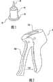
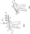
图1是用于本发明优选实施例的注射器药盒分配装置的注射器药盒(其中帽已经除去)的透视图。Figure 1 is a perspective view of a syringe cartridge (with the cap removed) for use in the syringe cartridge dispensing device of the preferred embodiment of the present invention.
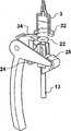
图2是用于分配单个注射器药盒(注射器药盒未示出)的注射器药盒分配装置的透视图。Figure 2 is a perspective view of a syringe cartridge dispensing device for dispensing a single syringe cartridge (syringe cartridge not shown).
图3是图2的注射器药盒分配装置的透视图,其中注射器药盒就位。Figure 3 is a perspective view of the syringe cartridge dispensing device of Figure 2 with the syringe cartridge in place.
图4是处于恰好在除去覆盖针头的防护帽之前的中性位置时注射器药盒分配装置的内部工件的透视图。Figure 4 is a perspective view of the internals of the syringe cartridge dispensing device in the neutral position just prior to removal of the protective cap covering the needle.
图5是在已经给药之后注射器药盒分配装置的内部工件的透视图。Figure 5 is a perspective view of the internals of the syringe cartridge dispensing device after a dose has been administered.
图6是注射器药盒分配装置的内部工件的透视图,其中触发器局部释放,且柱塞退回。Figure 6 is a perspective view of the internals of the syringe cartridge dispensing device with the trigger partially released and the plunger retracted.
图7是注射器药盒分配装置的内部工件的透视图,其中注射器药盒释放机构已经驱动。Figure 7 is a perspective view of the internals of the syringe cartridge dispensing device with the syringe cartridge release mechanism actuated.
图8是用于多个注射器药盒的注射器药盒分配装置的第二实施例的侧视图。Figure 8 is a side view of a second embodiment of a syringe cartridge dispensing device for multiple syringe cartridges.
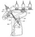
图9是图8中所示的注射器药盒分配装置的侧视图,其中多个注射器药盒装载在施加器中。Figure 9 is a side view of the syringe cartridge dispensing device shown in Figure 8 with a plurality of syringe cartridges loaded in the applicator.
图10是本发明优选实施例的注射器药盒分配装置的侧剖图。Figure 10 is a side sectional view of the syringe cartridge dispensing device of the preferred embodiment of the present invention.
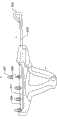
图10A是用于图10中所示的注射器药盒分配装置的优选注射器药盒的侧剖图。10A is a side cross-sectional view of a preferred syringe cartridge for use with the syringe cartridge dispensing device shown in FIG. 10 .
图11是注射器药盒分配装置的侧剖图,其中注射器药盒条带局部装载。Figure 11 is a side sectional view of the syringe cartridge dispensing device with the syringe cartridge strip partially loaded.
图12是注射器药盒分配装置的侧剖图,其中注射器药盒条带装载至停止位置。Figure 12 is a side sectional view of the syringe cartridge dispensing device with the syringe cartridge strip loaded to the stop position.
图13是注射器药盒分配装置的侧剖图,表示了药剂正部分供给。Figure 13 is a side sectional view of the syringe cartridge dispensing device showing the medicament being partially dispensed.
图14是注射器药盒分配装置的侧剖图,表示了全部药剂已供给。Figure 14 is a side cross-sectional view of the syringe cartridge dispensing device showing the entire medicament dispensed.
图15是注射器药盒分配装置的侧剖图,表示了柱塞完全返回和注射器药盒局部指引。Figure 15 is a side sectional view of the syringe cartridge dispensing device showing full plunger return and partial indexing of the syringe cartridge.
图16是注射器药盒分配装置的侧剖图,表示了把手完全返回和注射器药盒指引为准备用于下一个药剂供给。Figure 16 is a side sectional view of the syringe cartridge dispensing device showing the handle fully returned and the syringe cartridge indexed ready for the next dose of medicament.
图17是注射器药盒分配装置的还一实施例的侧视图。Figure 17 is a side view of yet another embodiment of a syringe cartridge dispensing device.
图18是图17的注射器药盒分配装置的透视图。18 is a perspective view of the syringe cartridge dispensing device of FIG. 17. FIG.
图18A是用于图17和18的注射器药盒分配装置的注射器药盒条带的侧视图。18A is a side view of a syringe cartridge strip for use with the syringe cartridge dispensing device of FIGS. 17 and 18 .
图18B是用于注射器药盒分配装置的注射器药盒条带的还一实施例的透视图。18B is a perspective view of yet another embodiment of a syringe cartridge strip for a syringe cartridge dispensing device.
图18C是用于注射器药盒分配装置的注射器药盒条带的还一实施例的透视图。18C is a perspective view of yet another embodiment of a syringe cartridge strip for a syringe cartridge dispensing device.
图19是注射器药盒分配装置的还一实施例的侧视图,其中注射器药盒保持组件具有变化。Figure 19 is a side view of yet another embodiment of the syringe cartridge dispensing device with a variation on the syringe cartridge retaining assembly.
图20是图19的注射器药盒分配装置的透视图。20 is a perspective view of the syringe cartridge dispensing device of FIG. 19 .
图21是注射器药盒分配装置的还一实施例的侧视图,其中注射器药盒保持组件进一步变化。Figure 21 is a side view of yet another embodiment of the syringe cartridge dispensing device with a further variation of the syringe cartridge retaining assembly.
图22是图21的注射器药盒分配装置的透视图。22 is a perspective view of the syringe cartridge dispensing device of FIG. 21. FIG.
图23是注射器药盒分配装置的还一实施例的侧视图,其中注射器药盒保持组件进一步变化。Figure 23 is a side view of yet another embodiment of the syringe cartridge dispensing device in which the syringe cartridge retaining assembly is further modified.
图24是图23的注射器药盒分配装置的透视图。24 is a perspective view of the syringe cartridge dispensing device of FIG. 23 .
图25是注射器药盒分配装置的还一实施例的侧视图,其中注射器药盒保持组件进一步变化。Figure 25 is a side view of yet another embodiment of the syringe cartridge dispensing device in which the syringe cartridge retaining assembly is further modified.
图26是图25的注射器药盒分配装置的透视图。26 is a perspective view of the syringe cartridge dispensing device of FIG. 25. FIG.
图27是注射器药盒分配装置的还一实施例的侧视图,其中注射器药盒保持组件进一步变化。Figure 27 is a side view of yet another embodiment of the syringe cartridge dispensing device in which the syringe cartridge retaining assembly is further modified.
图27A表示用于注射器药盒分配装置的注射器药盒条带的还一实施例。Figure 27A shows yet another embodiment of a syringe cartridge strip for use with a syringe cartridge dispensing device.
图28是图27的实施例的侧视图,但是表示了注射器药盒条带从前面推出,而不是从后面。Figure 28 is a side view of the embodiment of Figure 27 but showing the syringe cartridge strip being pushed out from the front rather than from the rear.
图29是注射器药盒分配装置和用于其中的注射器药盒条带的还一实施例的侧视图。Figure 29 is a side view of yet another embodiment of a syringe cartridge dispensing device and a syringe cartridge strip for use therein.
图30A至30N表示了用于多注射器药盒分配装置中的注射器药盒条带的还一实施例。Figures 30A to 30N show yet another embodiment of a syringe cartridge strip for use in a multiple syringe cartridge dispensing device.
图31A至31C表示了用于注射器药盒分配装置中的注射器药盒条带的还一实施例。Figures 31A to 31C show yet another embodiment of a syringe cartridge strip for use in a syringe cartridge dispensing device.
图32A至32C表示了用于注射器药盒分配装置中的注射器药盒条带的还一实施例。Figures 32A to 32C show yet another embodiment of a syringe cartridge strip for use in a syringe cartridge dispensing device.
图33是注射器药盒分配装置的还一实施例的侧视图。Figure 33 is a side view of yet another embodiment of a syringe cartridge dispensing device.
图34是图33的注射器药盒分配装置的透视图。34 is a perspective view of the syringe cartridge dispensing device of FIG. 33. FIG.
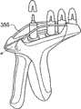
图35A至35D表示了注射器药盒分配装置的还一实施例。Figures 35A to 35D show yet another embodiment of a syringe cartridge dispensing device.
尽管实施例特别表示和介绍为用于乳房内抗生素的施加,但是应当知道这只是用于说明目的。Although the examples are specifically shown and described for the administration of intramammary antibiotics, it should be understood that this is for illustration purposes only.
注射器药盒分配装置可以用于需要从注射器分配流体的任意用途。而且,在这里的详细说明中,术语“药盒”用于普通意义。而且,术语“药盒”定义为用于保持流体的容器,几个合适的示例是注射器、弹仓、筒管和箱,且流体包括液体、气体和具有流体状特性的固体(例如粉末)以及它们的组合。它还有其他的用途,其中,本发明的装置可以用于没有针头尖端的药盒。The syringe cartridge dispensing device may be used in any application requiring the dispensing of a fluid from a syringe. Also, in the detailed description herein, the term "kit" is used in a generic sense. Also, the term "cartridge" is defined as a container for holding a fluid, a few suitable examples being syringes, magazines, barrels, and cases, and fluids include liquids, gases, and solids with fluid-like properties (such as powders) and their combination. It also has other uses where the device of the invention can be used in a medicine box without a needle tip.
具体实施方式Detailed ways
下面将通过本发明的优选实施例(即注射器药盒分配装置)来介绍本发明。本发明绝不局限于这些优选实施例,因为它们只是用于解释本发明,在不脱离本发明范围的情况下将包括很容易知道的可能变化和改变。The invention will be described below by way of a preferred embodiment of the invention, namely a syringe cartridge dispensing device. The present invention is by no means limited to these preferred embodiments, since they are only for explaining the present invention, and will include easily known possible variations and changes without departing from the scope of the present invention.
图1-7表示了本发明的一个实施例,该实施例涉及一种注射器药盒分配装置,用于分配单个注射器药盒的内容物,以便向动物提供单个剂量的药物。图8-29表示了本发明的还一实施例,这些实施例涉及一种注射器药盒分配装置,用于连续地分配多个注射器药盒的内容物,以便向一个或多个动物提供多个剂量的药物。Figures 1-7 illustrate an embodiment of the present invention relating to a syringe cartridge dispensing device for dispensing the contents of a single syringe cartridge to provide a single dose of drug to an animal. Figures 8-29 illustrate yet another embodiment of the present invention, which relates to a syringe cartridge dispensing device for sequentially dispensing the contents of a plurality of syringe cartridges to provide one or more animals with multiple dose of the drug.
各药盒(不管是单独的还是在载体条带上提供)具有针头尖端。在药盒用于抗生素的乳房内注射的情况下,针头尖端相对较短,因为这有利于处理(在单个药盒的情况下),还使它更容易除去保护帽。不过,在一些用途中可能需要更长的针头。附图只表示了附接在各药盒的分配端上的较短的针头。Each cartridge (whether provided individually or on a carrier strip) has a needle tip. In the case of a cartridge for intramammary injection of antibiotics, the needle tip is relatively short as this facilitates handling (in the case of a single cartridge) and also makes it easier to remove the protective cap. However, longer needles may be required in some applications. The figures show only the shorter needles attached to the dispensing end of each cartridge.
单个注射器药盒分配装置Single Syringe Cartridge Dispensing Device
单个注射器药盒分配装置(总体由图2的1表示)用于从注射器药盒3(图1)分配流体。注射器药盒3具有:本体4,该本体4形成具有侧壁和端部,用于容纳要分配的流体,该本体具有分配端5和非分配端6。分配端5用于允许流体通过较短针头在它的尖端从本体4排出,非分配端6用于并构成为允许柱塞从该非分配端进入和离开。装置1包括施加器触发器10,该施加器触发器通过枢转装置10a(图4)而与注射器药盒保持组件11可枢转地连接,其中,该触发器可沿第一方向12运动,如图2中所示。触发器10还操作附接在柱塞组件13,如图4-7中所示,这样,触发器10从伸出位置至退回位置的运动导致柱塞组件运动通过限定的冲程;从而从注射器药盒驱动流体。触发器10的形状和尺寸设置成在使用过程中在该施加器触发器从伸出位置运动至退回位置的过程中接收用户的手的至少4个手指。该装置的人机工程学很重要,特别是注射器药盒和喷嘴与用户的手和腕的角度或关系以及使得分配力在手中的更多肌肉群上的分布。A single syringe cartridge dispensing device (generally indicated at 1 in Figure 2) is used to dispense fluid from a syringe cartridge 3 (Figure 1). The
在所有的情况下,优选地药盒本体由透明或半透明的材料形成。通常,药盒本体应当由透明塑性材料吹塑模制或注射模制形成,这样,从动器(浮动柱塞)的位置将可见。实际上,优选地从动器(后面将介绍)具有颜色,这样,它向药盒本体下方的运动可以很容易检测。优选地,彩色从动器和透明或半透明本体的这种组合使得操作人员能够快速检测,以便看见药盒的内容物完全通过注射器的针头分配。In all cases it is preferred that the body of the cartridge is formed from a transparent or translucent material. Typically, the cartridge body should be blow molded or injection molded from a clear plastic material so that the position of the follower (floating plunger) will be visible. In fact, it is preferred that the follower (to be described later) be coloured, so that its movement down the body of the cartridge can be easily detected. Preferably, this combination of a colored follower and a transparent or translucent body enables the operator to quickly check to see that the contents of the cartridge are dispensed completely through the needle of the syringe.
注射器药盒保持组件11用于以预定角度以一定的方位或倾斜度来可拆卸地接收和保持在分配位置的注射器药盒3,该预定角度由第二方向14(注射器药盒和柱塞组件13的纵向轴线)相对于第一方向12来确定。该预定角度例如可以大于45度和小于135度,在60和120度之间、在75和105度之间,或者90度。The syringe
装置1还可以包括注射器药盒锁定组件16,该注射器药盒锁定组件16包括注射器药盒释放装置17,该注射器药盒释放装置17可在锁定位置和释放位置之间运动,在该锁定位置,注射器药盒释放装置17阻碍注射器药盒3从装置1释放,在该释放位置,注射器药盒释放装置17并不阻碍注射器药盒从装置1释放。注射器药盒锁定组件16阻碍注射器药盒释放装置从锁定位置运动至释放位置,直到注射器药盒3至少基本被分配,如图5中所示。The device 1 may also include a syringe
柱塞组件13包括可滑动地安装的浮动闩锁装置19,该浮动闩锁装置19可操作地附接在柱塞20上。柱塞20包括轴21,该轴21与头部部件22操作相连或连接。头部部件22的尺寸设置成滑动装配在注射器药盒本体中,以便在使用中允许柱塞20从注射器药盒3的非分配端运动至分配端。注射器药盒3具有从动器27(“浮动活塞”),该从动器位于注射器药盒3的非分配端处,且在使用时用于使得柱塞头部20能够抵靠并从注射器药盒本体推动流体。从动器具有O形环密封件,以便在药盒的液体内容物和柱塞之间提供无菌屏障。从动器的形状形成为与药盒的分配端的内部互补。这使得从动器能够进行推动直到药盒的筒管的端部,以便从药盒内排出基本全部液体。因为药盒具有限定的尺寸,并充满限定量的液体,因此当用于本发明的药盒分配装置时可以保证各药盒传递预定量的液体。注射器药盒释放装置17包括本体,该本体可枢转地与触发器10和柱塞组件13连接。注射器药盒释放装置17包括具有杠杆部分23的本体。The
触发器10包括臂24,因此,臂的一端固定地定位在触发器的一端处。臂的远端包括棘爪装置25,该棘爪装置25可滑动和可束缚地位于浮动闩锁装置19的轨道26中,以便在使用中当触发器10运动或旋转时向上运动,从而推动柱塞头部22,该柱塞头部22再推动注射器药盒从动器27,以便在注射器药盒本体内上下滑动,从而推动和分配液体内容物离开注射器药盒3。浮动锁定装置19包括空心或框架本体,该空心或框架本体可滑动地束缚柱塞杆21。
可以成弹簧形式的第一偏压装置(未示出)与注射器药盒释放装置17一起提供,用于偏压释放装置和注射器药盒至注射位置,并用于当注射器药盒释放装置17从锁定位置运动至释放位置时自动推出注射器药盒3。可以为作用在柱塞上的压缩弹簧的形式的第二偏压装置(未示出)提供使得触发器10到达它的静止或开始位置的回复力,如图2中所示。A first biasing means (not shown), which may be in the form of a spring, is provided with the
也可选择,药盒可以用手插入和用手推出。施加器的形状使得用户能够用他的拇指将药盒推动就位以及用他的拇指将用完的药盒推出。Alternatively, the cartridge can be manually inserted and manually ejected. The shape of the applicator enables the user to push the cartridge into place with his thumb and push the spent cartridge out with his thumb.
注射器药盒包括位于注射器药盒的非分配端处的突出部分。该突出部分可以为凸缘、唇缘或轮缘32的形式,它可以包括离散部分,或者成连续唇缘、轮缘或凸缘32的形式。注射器药盒分配装置1可以包括引导组件33,用于沿装载方向滑动地接收注射器药盒3,该装载方向定向成基本垂直于注射器药盒的纵向轴线14。引导组件33包括至少一个轨道(未示出),用于滑动地接收注射器药盒3的凸缘、唇缘或轮缘的一部分。The syringe cartridge includes a protruding portion at the non-dispensing end of the syringe cartridge. The protruding portion may be in the form of a flange, lip or
在使用时,注射器药盒分配装置具有前部37、后部面38、顶部39和底部40,如图3中所示。装置包括外壳,该外壳如图3中所示用作装置的机构和触发器10的盖部分35,还用作把手部分36,以便使得触发器能够相对于把手部分36运动。把手部分36还具有壳体,用于由第二偏压装置或压缩弹簧抵靠,以便提供用于柱塞的偏压力。还如图3中所示,盖部分35和触发器的顶部部分一起形成孔,该孔具有突出部分和内侧壁,该内侧壁具有引导组件33的轨道(未示出),以便形成注射器药盒保持组件11,因此,杠杆部分23和注射器药盒释放装置的一部分暴露为可见,因此,当注射器药盒在恰当位置被适当地向前推动直到抵靠盖部分35的内侧后部面38时,注射器药盒3可以从前部37装入轨道中,且注射器药盒基部6搁置在杠杆部分23上。In use, the syringe cartridge dispensing device has a front 37 , a rear face 38 , a top 39 and a bottom 40 as shown in FIG. 3 . The device comprises a housing which, as shown in FIG. 3 , serves as the mechanism of the device and as a cover portion 35 of the
注射器药盒从装置1的前部37装载。注射器药盒保持组件11各侧的突出部分防止注射器药盒竖直运动。注射器药盒保持组件11的侧壁防止注射器药盒水平或横向运动。当装载注射器药盒时,注射器药盒释放装置17向下(向旁边)枢转,从而使得注射器药盒3经过顶部。一旦注射器药盒3运动经过注射器药盒释放装置17,注射器药盒释放装置17就向上枢转(由作用在注射器药盒释放装置上的第一偏压装置或弹簧提供的力),并防止注射器药盒3向上运动。注射器药盒保持组件11的后壁防止注射器药盒进一步向后运动。在该阶段,注射器药盒被有效地限制和支承,而且还在施加器柱塞上面同心定位/对齐。推出弹簧位于注射器药盒保持组件的后部。当注射器药盒插入注射器药盒保持组件中时,注射器药盒相对于推出弹簧(未示出)推动,并使得弹簧“负载”。负载的推出弹簧(未示出)提供了用于推出用完的注射器药盒的力。Syringe cartridges are loaded from the front 37 of the device 1 . Projections on each side of the syringe
当注射器药盒具有防护帽时,将它除去。然后,施加器触发器10可以挤压,以便开始它的冲程,从而进行一定剂量的给药。当挤压触发器时,触发器臂24沿逆时针的圆弧向上运动。触发器臂24相对于柱塞组件13作用,并使得柱塞组件13竖直向上运动。柱塞组件13被引导成使得它只能沿竖直方向运动。在触发器臂24和柱塞组件13之间的交界面(接触表面/连接件)使得触发器臂进行旋转运动,同时柱塞只进行竖直运动。在柱塞组件13上的、触发器臂24作用在其上的交界面向柱塞的后侧偏移。这使得触发器10的枢转装置10a能够运动成更靠近柱塞组件13的轴线14,同时还保持相同运动比率(在触发器10和柱塞组件13之间的运动比率)。柱塞组件13的轴线14对于注射器药盒分配装置的人机工程学很重要,因为柱塞组件13的角度确定了注射器药盒3的角度。另一有用特征是从触发器的前部至把手的后部的距离-施加器的所有用户应当能够舒服地用他们的手指到达触发器,而并不拉伸他们的手。通过使得触发器的枢转点运动成更靠近柱塞,触发器可以保持更靠近把手,且整个单元可以保持更紧凑。When the syringe cartridge has a protective cap, remove it. The
当柱塞组件13向上运动时,它带动浮动闩锁装置19(与它一起)。恰好在柱塞组件13到达它的冲程的顶部(因此基本全部流体已经从注射器药盒分配)时,浮动闩锁装置19推动经过在注射器药盒释放装置17上的柔性卡住件或杠杆部分23。当触发器10释放时,柱塞组件13开始向下运动,不过,浮动闩锁装置19并不运动,因为它由注射器药盒释放装置17保持。作用在柱塞组件13上的较大压缩弹簧(未示出)提供了使得触发器臂24和触发器10返回它的静止/开始位置的力。As the
当柱塞组件13开始向下运动时,它离开从动器27的后面,因为这时它贴切地向上推靠在分配端的内部。如上所述,通过由透明或半透明材料例如PET或者其它合适的塑性材料(或者在某些情况下由玻璃)制造药盒的本体,从动器的位置将很容易由用户看见,且他能够进行检测,以便看见药盒的内容物完全分配。When the
当柱塞组件13接近它的冲程底部时,浮动闩锁装置19开始向下运动(由柱塞头部22拉动),再沿顺时针圆弧向下拉动注射器药盒释放装置17。在该阶段,柱塞组件13这时从注射器药盒3完全退回(在它的冲程的底部或开始处)。当注射器药盒释放装置17运动至低于注射器药盒3的凸缘32时,注射器药盒3不再从前部被保持,且注射器药盒3通过由推出弹簧(未示出)提供的力而从注射器药盒分配装置推出。该释放作用在图7中表示。As the
当柱塞组件13到达它的冲程端部时,注射器药盒释放装置17继续沿弧线向下运动和离开浮动闩锁装置19。当在注射器药盒释放装置17和浮动闩锁装置19之间不再有任何接合时,浮动闩锁装置下落经过注射器药盒释放装置17,且机构复位,以便再次开始由触发器10驱动。As the
如果只施加部分药剂且触发器释放,则该装置防止药盒释放,直到全部药剂已经施加。该特征在处理动物时很有利,例如当动物脚踢和用户快速收回给出药剂的施加器部分时。If only part of the dose is applied and the trigger is released, the device prevents release of the cartridge until the full dose has been applied. This feature is advantageous when handling animals, such as when the animal kicks and the user quickly retracts the portion of the applicator that dispenses the medicament.
多个注射器药盒分配装置Multiple Syringe Cartridge Dispensing Device
如图8和9中所示,注射器药盒分配装置100用于从注射器药盒条带101上的一个或多个注射器药盒中分配流体。注射器药盒条带101包括四个注射器药盒102,这四个注射器药盒102形成或附接在共同的柔性基部条带103上。任意数目的注射器药盒可以形成于该条带上,不过,在该特殊实施例中表示了四个注射器药盒,因为施加器特别用于乳房内施药,且奶牛有四个乳头,这样,一组注射器药盒可以用于处理一个奶牛的乳房。各注射器药盒102具有分配端114和非分配端115。As shown in FIGS. 8 and 9 , a syringe
注射器药盒分配装置100包括施加器触发器104、把手116、容纳于壳体107内的注射器药盒保持组件106和柱塞组件105。施加器还可以包括指引组件(图8和9中未示出)。尽管在它的最简单形式中,基于条带的形式可能依赖于用户的拇指来使得条带沿轨道运动,以便每次将一个药盒定位在分配位置。当它们附接在条带上时,用完的药盒将被推开,因为下一个满的药盒运动至该位置。Syringe
施加器触发器104可沿第一方向从伸出位置向退回位置运动。柱塞组件105与触发器104交接,这样,触发器从伸出位置至退回位置的运动导致柱塞组件从各注射器药盒驱动流体。注射器药盒保持组件106用于可拆卸地接收和保持注射器药盒条带101和在分配位置的各单个注射器药盒101。优选地,注射器药盒的纵向轴线相对于第一方向倾斜预定角度,该预定角度在大约5-90度之间,优选地小于大约45度。也可选择,注射器药盒的纵向轴线可以布置成基本与第一方向平行,如图33-35中所示。The
注射器药盒保持组件106包括开有狭槽或孔的支承部件,用于支承注射器药盒条带的条带103,还允许接近柱塞组件。柱塞组件105包括:柱塞,该柱塞具有与杆部分连接的头部部分,该杆部分装于管形支承件中;以及偏压装置。The syringe
施加器触发器104与把手116可旋转地连接。触发器104还与杠杆臂组件可枢转地连接,该杠杆臂组件包括杠杆臂111和112。杠杆臂112的一端与触发器104的下部部分可枢转地连接,杠杆臂111的另一端与把手116内的柱塞杆的下端可枢转地连接。把手116的尺寸类似于单个注射器药盒分配装置的把手,它用于允许手握住它,还使得手指能够舒适地握住和使得触发器运动。
触发器的另一端可滑动地安装在弯曲轨道中,以便当由用户驱动时允许触发器绕下部枢转部旋转。如图9中所示,与柱塞杆的下端连接的杠杆臂111由辊装置113可旋转地支承,这样,在使用中,当触发器由用户驱动时,杠杆臂111和112旋转和绕在它们之间的枢转点进行枢转,同时杠杆臂111运动越过辊113,以便向上推动柱塞,并从注射器药盒排出流体内容物。The other end of the trigger is slidably mounted in the curved track to allow the trigger to rotate about the lower pivot when actuated by the user. As shown in Figure 9, the
图10和10A表示了注射器药盒分配装置(总体以200表示),它用于和构成为能够从单个注射器药盒203中分配至少一个剂量的药剂。单个注射器药盒203可以与至少一个其它注射器药盒203组合或者可拆卸地附接在至少一个其它注射器药盒203上,以便形成注射器药盒条带204,各注射器药盒具有在其中的可分配产品。装置200可以与图1-6中所示的装置1相似地构成,因此包括施加器触发器205,该施加器触发器205可旋转地附接在柱塞组件206上。柱塞206可滑动地附接在把手207上,该把手207与施加器触发器205一起形成具有上端208和下端209的壳体。触发器205在使用时位于施加器的前部210处,把手207位于后部211处。10 and 10A show a syringe cartridge dispensing device (generally indicated at 200 ) for use and configured to dispense at least one dose of medicament from a
触发器205与把手207在它的下端处的枢转部212处可枢转地连接,触发器的上端与指引组件可枢转地连接。指引组件包括指引连杆214、指引支架216、指引爪220和指引止动器223。指引连杆214是杠杆或杆或细长条带,它在一端处与触发器205可枢转地连接,在另一端处与指引支架216可枢转地连接。指引支架216通过位于各端的辊218和219而可滑动地定位于轨道217中。具有指引爪止动面221的指引爪220附接在指引支架216的上部面上,以便在使用中在与轨道217平行的平面中滚转,并当朝着施加器的前部210运动时停止。设置止动凸轮222和指引止动器223。指引止动器223包括杆形部件,该杆形部件具有止动端,且在与止动凸轮222之间固定有弹簧。止动凸轮222包括可旋转地附接在壳体上并可偏压地对着壳体运动的部件,以便提供朝外的凸轮表面,在使用时,该凸轮表面允许触发器205的上端进行抵靠凸轮运动。The
止动凸轮222与把手207可旋转地连接,并由弹簧222a沿向下方向偏压。止动凸轮222通过支承在下部凸轮表面上的触发器205的作用而旋转。止动销222b防止止动凸轮222过度旋转。指引止动器223包括能够沿平行于柱塞206的轴线滑动的部件、止动端223a和抵靠件223b。弹簧223c布置在止动凸轮222和指引止动器223之间,以便将止动端223a偏压至停止位置(指引止动器延伸超过轨道)。在静止位置,触发器205支承在止动凸轮222上,从而向上推动它,这使得指引止动器223升高至指引停止位置,这提供了止动表面,在注射器药盒条带204的初始装载过程中该注射器药盒条带204抵靠该止动表面。The
在操作过程中,触发器205旋转至退回位置,止动凸轮222离开触发器205的凸轮表面205a,并向下旋转直到止动凸轮222抵靠止动销222b。该动作使得指引止动器223退回(指引止动器退回,准备用于注射器药盒条带204的指引)。在注射器药盒的内容物进行分配之后,触发器205能够旋转至伸出位置,从而使得注射器药盒条带204能够在指引爪220的作用下通过指引连杆214向前指引。当触发器205接近它的完全伸出位置时,凸轮表面205a使得止动凸轮222向上旋转,这又使得向上的偏压施加在指引止动器223上。指引止动端223a不能完全升高,直到注射器药盒条带204的指引孔240恰好在它上面,因此指引止动器223升高至指引止动位置。During operation, the
柱塞206具有在上端的头部部分224和位于头部部分224的下面并抵靠该头部部分224的下面的返回弹簧225。在柱塞下端处的引导块226、柱塞释放杠杆227和柱塞释放爪228与柱塞操作连接。柱塞释放爪228包括可通过返回弹簧228A操作的L形中心旋转部件。杠杆227包括Z形部件,因此中心部分具有在各端的钩,该钩的尺寸设置成并用于在使用时与释放爪228的一部分接合。飞旋镖形传递连杆229也附接在柱塞组件上,该传递连杆229在它的另一端可旋转地附接在施加器触发器205的下端上。The
图10A表示了注射器药盒条带204的示例,通过该注射器药盒条带204,注射器药盒203在非分配端处与连接支承条带235连接,该连接支承条带235在条带上的各注射器药盒之间的部分较脆弱或可切断。注射器药盒条带204具有前端236和后端237。支承条带235具有位于注射器药盒条带204的各注射器药盒203之间的指引孔240,以便当注射器药盒条带用于注射器药盒分配装置时能够指引注射器药盒。FIG. 10A shows an example of a
如图11中所示,注射器药盒条带204插入和装入位于施加器上侧后部的注射器药盒保持组件238中,直到条带236的前端遇到指引止动器223或由指引止动器223停止。当注射器药盒条带装入注射器药盒保持组件中时,第一注射器药盒的非分配端在指引爪220上面运行和将其压下。在第一注射器药盒在指引爪220上面运行之后,指引爪220再向上旋转,以便通过指引孔240而与注射器药盒条带235接合,从而保持注射器药盒牢固就位,如图12中所示。As shown in FIG. 11 , the
为了使用注射器药盒分配装置,施加器触发器205朝着把手207压下。图13表示了在使用中的装置,其中,触发器被部分压下,药剂部分供给。触发器205通过枢转部212而与把手207可旋转地连接,且触发器205通过传递连杆229和后部连杆230而与柱塞组件206可操作地连接,这样,当触发器驱动时,它使得柱塞206相对于把手207以一定角度向上运动,这样,它与要进行分配的单个注射器药盒一致,因此,柱塞头部224操作成从注射器药盒中推动和排出注射器药盒内容物。传递连杆229旋转,同时引导块226与柱塞释放杠杆227一起向上平移运动,且通过抵靠表面206a使得柱塞206升高。当引导块226和释放杠杆227以及柱塞206升高时,柱塞释放爪228相对于柱塞释放爪返回弹簧228a的偏压力而可旋转地移动。To use the syringe cartridge dispensing device, the
图13还表示了药盒本体和至少它的产品分配部分稍微从壳体突出。这使得用户能够在从动器27朝着它的冲程端部运动以便与药盒本体的分配端的内部接触时看见从动器27的运动。因此,药盒的定位和药盒本体的透明或半透明性质提供了对装置操作的可视检查。Figure 13 also shows that the body of the cartridge and at least its product dispensing portion protrude slightly from the housing. This enables the user to see the movement of the
还有,当驱动触发器205时,触发器205的上端抵靠止动凸轮222的下部凸轮表面进行凸轮运动,这样,止动凸轮222在弹簧的作用下下降,从而使得止动凸轮222向下弹起,以便降低或拉低指引止动器223。还有,如图13中所示,指引连杆214向装置的右侧或后部运动,从而使得指引支架216与它一起滚转,从而压下或拴牢指引爪220。Also, when the
图14表示了当全部药剂已经传送时的注射器药盒分配装置。柱塞头部224压下至注射器药盒中直到它能够运行的位置,且柱塞释放杠杆227越过柱塞释放爪228的端部,这样,柱塞释放爪228在返回弹簧228a的作用下逆时针方向旋转。还有,指引支架216这时到达支架轨道217的端部,由此,指引爪220在第二和第三注射器药盒之间的指引孔240中与注射器药盒条带接合。Figure 14 shows the syringe cartridge dispensing device when the entire medicament has been delivered.
图15和16表示了在药剂已经给出和触发器205已经释放之后注射器药盒分配装置的工件。如图15中所示,当触发器205返回时,这使得柱塞206完全退回,同时注射器药盒条带235在指引止动器223上面引导,因为指引止动器223由止动凸轮222向下拉动。在注射器药盒指引之前,杠杆227释放柱塞206,这样,柱塞206从注射器药盒条带235完全退回,且在把手返回弹簧的作用下,指引支架216通过指引连杆214和触发器205而向前拖动。指引爪220朝着触发器205向前拉动注射器药盒条带235,这样,下一个注射器药盒布置在分配位置中。Figures 15 and 16 show the components of the syringe cartridge dispensing device after the dose has been administered and the
图16表示了触发器205返回至开始位置,其中,第一注射器药盒这时排空它的内容物,从而已经给药。这时,第一注射器药盒准备从注射器药盒分配装置切除或推出,或者将只是向前运动,直到全部注射器药盒都分配或排空且整个注射器药盒条带从装置上除去或推出为止。这时,柱塞组件206与第二注射器药盒对齐,从而准备在再次按压触发器205时分配它的内容物。柱塞释放杠杆227与柱塞206重新接合,指引支架216拉向轨道217的左端或前端,指引爪220的止动器在第二和第三注射器药盒之间与注射器药盒条带235接合,但是准备在需要时拴牢。触发器205的释放将指引止动凸轮223推入注射器药盒指引孔240中,以便提供止动。Figure 16 shows the return of the
图17-29表示了注射器药盒分配装置的可能实施例的其他示例,其中,位于装置本体的上部部分上的注射器药盒保持组件的结构变化。通常,注射器药盒保持组件具有U形部分,该U形部分用于允许注射器药盒条带插入。U形部分具有基部和侧壁。根据用于装置中的注射器药盒条带的形状或类型,基部可以包括槽或其它特征。通常,U形部分延伸装置的上部部分的整个长度,以便注射器药盒条带容易插入和推出。Figures 17-29 show further examples of possible embodiments of the syringe cartridge dispensing device in which the configuration of the syringe cartridge retaining assembly on the upper part of the device body is varied. Typically, the syringe cartridge holder assembly has a U-shaped portion for allowing insertion of a syringe cartridge strip. The U-shaped portion has a base and side walls. Depending on the shape or type of syringe cartridge strip used in the device, the base may include grooves or other features. Typically, the U-shaped portion extends the entire length of the upper portion of the device for easy insertion and ejection of the syringe cartridge strip.
图17和18表示了注射器药盒分配装置(总体表示为300),该注射器药盒分配装置包括上部部分302、下部部分303、后部部分304和前部部分306。装置的上部部分302包括呈U形部分形式的注射器药盒保持组件(总体表示为310)。注射器药盒保持组件310具有基部309和侧壁308,该侧壁308形成轨道或滑道,该轨道或滑道在使用时容纳注射器药盒条带。侧壁308可以具有窗口311。在各侧壁308的基部具有接收部分315,该接收部分315的尺寸和形状设置成容纳要在装置中使用的注射器药盒条带的基部。注射器药盒分配装置300具有施加器触发器319和后部把手320。如上所述,施加器触发器319可旋转和操作地与后部把手320连接和与内部柱塞组件(未示出)连接,以便能够在需要时连续供给注射器药盒条带的各注射器药盒。注射器药盒在后部部分304处插入装置中,且在使用过程中在分配各注射器药盒的内容物时,注射器药盒朝着前部部分306运动(通过指引组件的操作)。用完的注射器药盒将悬垂在装置的前部部分上,直到注射器药盒条带从装置中除去或推出为止。17 and 18 show a syringe cartridge dispensing device (generally designated 300 ) comprising an
装置的注射器药盒保持组件310可以包括用于在分配内容物之前从注射器药盒上除去防护帽的机构。例如,在图17和18中,各注射器药盒具有保护帽,该保护帽可通过挤压机构来除去。因此,装置的注射器药盒保持组件310可以包括在各侧壁上的机构,例如相对凹槽等,该机构用于在注射器药盒处于正确的分配位置时挤压注射器药盒的顶部,以便在注射器药盒的内容物进行分配之前从该注射器药盒上自动除去防护帽。The syringe
图18A-18C表示了注射器药盒条带(总体表示为305)的一些示例,它们可以用于注射器药盒分配装置中。通常,注射器药盒条带包括:基部部分,该基部部分用于连接多个间隔开的注射器药盒,各注射器药盒具有:本体,该本体用于容纳要分配的流体;分配端,该分配端用于使得流体能够从本体排出;以及非分配端,该非分配端用于使得注射器药盒分配装置的柱塞能够与它接合,以便从注射器药盒排出流体。注射器药盒条带305的形状和结构可以根据装置的注射器药盒保持组件310的形状和结构以及由装置使用的指引组件的类型而变化,以使得注射器药盒运动通过该装置。例如,图18A表示了具有在各注射器药盒之间的六角形风琴形状连杆328的注射器药盒条带305。Figures 18A-18C show some examples of syringe cartridge strips (generally designated 305) that may be used in a syringe cartridge dispensing device. Typically, a syringe cartridge strip includes a base portion for connecting a plurality of spaced apart syringe cartridges, each syringe cartridge having a body for containing a fluid to be dispensed, a dispensing end for dispensing end for enabling fluid to be expelled from the body; and a non-dispensing end for enabling a plunger of the syringe cartridge dispensing device to engage it to expel fluid from the syringe cartridge. The shape and configuration of the
当注射器药盒分配装置用于自动指引注射器药盒时,注射器药盒条带的基部部分优选地包括指引装置。图18B表示了具有基部部分325的注射器药盒条带305,该基部部分325具有成位于各间隔开的注射器药盒之间的指引孔326形式的指引装置,以便当在使用中指引爪与注射器药盒条带接合时容纳注射器药盒分配装置的指引爪。图18C表示了具有基部部分325的注射器药盒条带305,该基部部分325具有成一对相对凹口327形式的指引装置,该相对凹口327在各间隔开的注射器药盒之间位于基部部分的各边缘上,以便当在使用中指引爪与注射器药盒条带接合时容纳注射器药盒分配装置的指引爪。When the syringe cartridge dispensing device is used for automatic indexing of the syringe cartridges, the base portion of the syringe cartridge strap preferably comprises indexing means. FIG. 18B shows a
图19和20表示了注射器药盒分配装置的另一示例,它与图17和18的实施例类似,不过,侧壁具有切除部分353,以便提高可视性和使得手指接近装置的注射器药盒保持组件和注射器药盒条带(当装入其中时)。切除的侧壁353可以具有由不锈钢或其它材料制造的导轨355,该导轨355可以用于在分配内容物之前从注射器药盒除去防护帽。Figures 19 and 20 show another example of a syringe cartridge dispensing device, which is similar to the embodiment of Figures 17 and 18, however, the side wall has a cut-out 353 to improve visibility and allow finger access to the syringe cartridge of the device Retains the assembly and syringe cartridge strip (when loaded therein). The cut away
图21和22表示了注射器药盒分配装置的还一实施例。在该实施例中,注射器药盒保持组件363沿它的长度都没有侧壁361。在装置前部部分362处的侧壁切除,只留下接收机构360,用于在使用时接收注射器药盒条带的基部。箭头表示了注射器药盒条带在装置操作过程中的运动的总体方向。注射器药盒条带从后部部分366装载,并朝着前部部分362运动。在该实施例中,切除的侧壁361允许在分配注射器药盒之前从注射器药盒上人工除去任何防护帽。Figures 21 and 22 show yet another embodiment of a syringe cartridge dispensing device. In this embodiment, the syringe
图23和24表示了注射器药盒分配装置的还一实施例。在该实施例中,注射器药盒保持组件包括侧壁371,该侧壁371用于容纳突出的环形导轨378,该环形导轨可以固定在侧壁内或者可以在侧壁内滑动,这样,它可以被人工推动,以便能够指引注射器药盒381。该实施例使得注射器药盒条带能够从后部376装载,并在使用时朝着前部372运动,同时人工除去在注射器药盒上的任何防护帽380。装置可以包括切割装置383例如刀片,例如成棘爪形式,它可以独立或者与施加器触发器连接,以便在各注射器药盒用完时切割或切断各注射器药盒。图25和26表示了注射器药盒分配装置的一个实施例,它非常类似于图23和24,除了环形导轨只在一端398处为环形,只是从装置的后部396突出,并不从前部突出。导轨398也可以固定或者可滑动地附接在装置的注射器药盒保持组件的侧壁上。再有,注射器药盒分配装置可以包括切割装置399,例如刀片,例如成棘爪形式,它可以独立或者与施加器触发器连接,以便在各注射器药盒用完时切割或切断各注射器药盒。Figures 23 and 24 show yet another embodiment of a syringe cartridge dispensing device. In this embodiment, the syringe cartridge retaining assembly includes a
图27表示了注射器药盒分配装置的还一变化形式,它包括导轨455,该导轨455从前部突出,而不是后部,且该导轨能够从前部装载注射器药盒条带和从后部推出。它还可以提高可视性和容易使用。图27A表示了注射器药盒条带的实施例,其中,注射器药盒具有固定的间隔连接部456。Figure 27 shows yet another variation of the syringe cartridge dispensing device that includes a
图28表示了注射器药盒分配装置的还一变化形式,类似于图27,它表示了注射器药盒条带可以从前部装载,用完的注射器药盒的除去或推出也可以在装置的前部进行。Figure 28 shows yet another variant of the syringe cartridge dispensing device, similar to Figure 27, which shows that the strips of syringe cartridges can be loaded from the front, and the removal or ejection of the spent syringe cartridges can also be at the front of the device conduct.
图29表示了注射器药盒分配装置的实施例的另一变化形式,它用于接收不同类型的注射器药盒条带。在该示例中的注射器药盒条带605成具有多个喷嘴606的单个圆柱形容器的形式,这些喷嘴606具有各自的防护帽607。指引组件与注射器药盒条带605连接,该注射器药盒条带605具有指引装置608,该指引装置608附接在条带605的一部分上或者形成该条带605的一部分,该注射器药盒条带605中具有凹槽或凹口610,用于在使用时与注射器药盒分配装置的指引爪接合。该指引组件能够在需要时通过用户推动或移动指引装置608而人工指引注射器药盒。注射器药盒分配装置具有注射器药盒保持组件,该注射器药盒保持组件具有切除的侧壁(总体表示为611),这使得注射器药盒条带605能够可滑动地插入以及能够人工除去任何防护帽。Figure 29 shows another variation of the embodiment of the syringe cartridge dispensing device for receiving different types of syringe cartridge strips. The
本领域技术人员应当知道,这里所述的注射器药盒分配装置的任意实施例都用于沿任意方向装载和除去或推出注射器药盒条带。例如,装置可以用于从前部装载注射器药盒条带,且在使用时注射器药盒向后部运动,并随后从后部除去或推出用过的注射器药盒。类似地,注射器药盒条带可以从施加器的相同部分装载、然后除去或推出,例如从前部装载和推出,或者从后部装载和推出。Those skilled in the art will appreciate that any of the embodiments of the syringe cartridge dispensing device described herein can be used to load and remove or eject a strip of syringe cartridges in any direction. For example, the device may be used to load a strip of syringe cartridges from the front, and in use the syringe cartridges are moved to the rear, and the spent syringe cartridges are subsequently removed or ejected from the rear. Similarly, a syringe cartridge strip can be loaded and then removed or ejected from the same part of the applicator, eg from the front, or from the rear.
图30A至30N表示了注射器药盒条带的实施例,其中,注射器药盒的内容物密封在注射器药盒中,这样,注射器药盒能够在需要时长时间储存而并不使用。如图30A中所示,注射器药盒具有分配端701和基部部分703,该基部部分703形成将全部注射器药盒附接在一起的条带。优选地,该条带由PET层压材料形成,且各药盒的条带和本体702都由相同材料形成。通常,各药盒可以由PET条带材料吹塑模制形成,且传送尖端包括附接在该端部的针头。注射器药盒还具有筒管702,该筒管702容纳注射器药盒的密封内容物。优选地,内容物由铝密封件来热封。图30B是图30A的剖视图,表示了当注射器药盒分配装置的柱塞并不驱动时注射器药盒的内部。注射器药盒包括穿刺机构704,该穿刺机构704在需要释放注射器药盒的内容物705时穿刺该密封件。注射器药盒还包括从动器706,该从动器706位于注射器药盒的非分配端,该从动器706在使用时用于允许柱塞(未示出)的头部抵靠,并从注射器药盒朝着注射器药盒的分配端701推动流体。图30C是表示在注射器药盒分配装置的柱塞驱动后注射器药盒的内部的剖视图。当柱塞驱动时(通过施加器触发器的操作),柱塞707的头部(该头部的尺寸设置成可滑动地装配在注射器药盒本体内)推动从动器706,该从动器706再朝着注射器药盒的分配端701向上推动注射器药盒的内容物705,这样,密封件到达穿刺机构704,该穿刺机构704刺穿密封件,从而能够向注射器药盒的分配端释放注射器药盒的内容物,从而能够向要处理的动物来释放。自穿刺机构和方法在图30N中表示。在该图中,在左侧的位置是在柱塞操作之前,这样,热封的铝箔709提供了可靠的密封,用于药盒本体内的液体。密封件恰好在穿刺嘴704下面。在中间视图中,柱塞向上按压从动器至药盒的本体中,这样,液体容积迫使铝箔709向上与穿刺嘴704接触。标号709A表示了穿刺嘴恰好穿刺铝箔。在图30N的右手侧的第三视图中,活塞继续推动从动器进一步向上进入药盒的本体中,从而迫使液体在分配端的喉部撕破铝箔,且标号709B表示铝箔的破裂状态,这样,液体通过分配端向上通过针头尖端排出。在图30A至30C中,注射器药盒的筒管从注射器药盒条带的单侧定位或突出。不过,注射器药盒的全部或部分筒管可以从注射器药盒条带的底侧定位或突出(图30E),而注射器药盒的分配端从另一侧突出(图30D)。柱塞在注射器药盒内部的操作相同,如图30F和30G中所示。Figures 30A to 30N show an embodiment of a syringe cartridge strip in which the contents of the syringe cartridge are sealed within the syringe cartridge so that the syringe cartridge can be stored for extended periods of time if needed without being used. As shown in Figure 3OA, the syringe cartridge has a dispensing
图30H至30M表示了在注射器药盒条带上的注射器药盒的类似实施例;不过,注射器药盒的筒管为六角形风琴形状,以便帮助释放注射器药盒的内容物。通过注射器药盒条带的该实施例,柱塞组件不需要形成或用于进入注射器药盒本体,以便排出它的内容物。而且,柱塞组件可以用于与注射器药盒的表面接触或向该表面施加力,这导致包装材料压缩或受到较大挤压,以便减小它的内部容积,这又使得注射器药盒的内容物受到挤压或压向注射器药盒的分配端,从而导致排出内容物。图30H至30J表示了单侧实施例,其中,注射器药盒的筒管702只附接在条带的一侧或只从一侧突出,而图30K至30M表示了双侧实施例,其中,注射器药盒的全部或部分筒管702从条带的底侧突出,分配端701从另一侧突出。Figures 30H to 30M show a similar embodiment of a syringe cartridge on a syringe cartridge strip; however, the barrel of the syringe cartridge is concertina shaped to aid in releasing the contents of the syringe cartridge. With this embodiment of the syringe cartridge strip, a plunger assembly need not be formed or used to enter the syringe cartridge body in order to expel its contents. Moreover, the plunger assembly may be used to contact or apply a force to a surface of the syringe cartridge, which causes the packaging material to compress or be substantially compressed, so as to reduce its internal volume, which in turn makes the contents of the syringe cartridge The contents are squeezed or pressed against the dispensing end of the syringe cartridge, causing the contents to be expelled. Figures 30H to 30J show a single-sided embodiment, in which the
图31A至31C也表示了注射器药盒条带的实施例,其中,各注射器药盒的内容物密封在膜盒形囊袋中。图31A表示了具有囊袋的至少一部分的注射器药盒条带的一侧,且分配端710从该囊袋突出,而图31B表示了条带的底侧,囊袋711的其余部分从该底侧突出。图31C是注射器药盒条带的剖视图,表示了注射器药盒712的密封内容物和穿刺机构713。当注射器药盒分配装置(未示出)驱动时,柱塞组件将沿箭头方向推动囊袋,从而使得穿刺机构穿刺囊袋的密封件,并释放它的内容物。图32A至32C表示了注射器药盒条带的类似实施例,其具有不同形状的囊袋(细长和扁平,而不是膜盒形状)。当使用这些注射器药盒条带时,柱塞组件不需要形成或用于进入注射器药盒本体以便排出它的内容物。而且,柱塞组件可以用于与注射器药盒的表面接触或向该表面施加力,这导致包装材料压缩或受到较大挤压,以便减小它的内部容积,这又使得注射器药盒的内容物受到挤压或压向注射器药盒的分配端,从而导致排出内容物。Figures 31A to 31C also show an embodiment of a syringe cartridge strip in which the contents of each syringe cartridge are sealed in a bellows-shaped pouch. Fig. 31 A has represented the side of the syringe cartridge strip with at least a part of pouch, and dispensing
图35A至35D表示了注射器药盒分配装置的另一可能实施例,优选地使用具有密封囊袋的注射器药盒条带,例如如图31A至31C和32A至32C中所示。在注射器药盒分配装置的该实施例中,注射器药盒保持组件定位成环绕装置的壳体的周边,且注射器药盒条带环绕装置的周边供给,而不是通过装置的上表面供给。装置可以包括防护罩725,以便防止在使用过程中交叉污染。防护罩具有孔726,当药剂进行给出时,注射器药盒的分配端727从该孔突出。图35C表示了施加器触发器729怎样与柱塞组件730操作连接,该柱塞组件730包括在它的端部的压缩垫731,该柱塞组件730通过渐变的压缩力的操作来保证当药剂给出时该注射器药盒的全部内容物都排出(见图35D)。压缩垫731并不必须进入各注射器药盒以便排出内容物,而是用于与注射器药盒的表面接触或向该表面施加力,这导致包装材料压缩或受到较大挤压,以便减小它的内部容积,这又使得注射器药盒的内容物受到挤压或压向注射器药盒的分配端,从而导致排出内容物。Figures 35A to 35D show another possible embodiment of a syringe cartridge dispensing device, preferably using a syringe cartridge strip with a sealed pouch, such as shown in Figures 31A to 31C and 32A to 32C. In this embodiment of the syringe cartridge dispensing device, the syringe cartridge retaining assembly is positioned around the perimeter of the housing of the device, and the syringe cartridge strip is fed around the perimeter of the device rather than through the upper surface of the device. The device may include a
图33和34表示了注射器药盒分配装置的还一实施例,该注射器药盒分配装置可以使用这里所述的任意注射器药盒条带。装置具有成嵌齿715形式的指引组件,该嵌齿715与柱塞组件716和施加器触发器717操作连接并用于使得注射器药盒条带前进,这样,注射器药盒装载在正确位置,用于连续供给药剂。注射器药盒条带从装置的后部718插入,且用完的注射器药盒可以从装置的前部719推出或除去,或者可以在使用后捕获于装置内部。装置的后部把手720可以附接在枢转点721上,该枢转点721允许在供给药剂时调节装置的角度。图34表示了装置的上部部分,注射器药盒保持组件722位于该上部部分中,用于在使用中接收注射器药盒条带。注射器药盒保持组件可以由防护罩723覆盖,以便在使用时避免注射器药盒的任意可能污染。防护罩723具有孔724,注射器药盒的分配端从该孔724突出,以便向动物给药。Figures 33 and 34 show yet another embodiment of a syringe cartridge dispensing device that can use any of the syringe cartridge strips described herein. The device has an indexing assembly in the form of a cog 715 which is operatively connected to the plunger assembly 716 and applicator trigger 717 and which is used to advance the syringe cartridge strip so that the syringe cartridge is loaded in the correct position for Continuous supply of potions. The syringe cartridge strip is inserted from the rear 718 of the device, and a spent syringe cartridge can be pushed out or removed from the front 719 of the device, or can be captured inside the device after use. The rear handle 720 of the device may be attached to a pivot point 721 that allows the angle of the device to be adjusted when administering the medicament. Figure 34 shows the upper portion of the device in which the syringe cartridge holder assembly 722 is located for receiving a syringe cartridge strip in use. The syringe cartridge holding assembly may be covered by a protective cover 723 in order to avoid any possible contamination of the syringe cartridge when in use. The shield 723 has an aperture 724 through which the dispensing end of the syringe cartridge protrudes for administering the drug to the animal.
通常,多个注射器药盒分配装置的使用包括以下步骤:Typically, the use of a multiple syringe cartridge dispensing device involves the following steps:
将注射器药盒条带人工装载至装置的注射器药盒保持组件中,直到指引止动器驱动,且第一注射器药盒处于分配位置;Manually load the syringe cartridge strip into the syringe cartridge retaining assembly of the device until the index stop is actuated and the first syringe cartridge is in the dispensing position;
按压施加器触发器,从而使得柱塞组件驱动(因此使得第一注射器药盒的内容物被分配),同时使得指引组件开始将注射器药盒条带上的下一个注射器药盒定位在分配位置中的过程;Depressing the applicator trigger causes the plunger assembly to drive (thus causing the contents of the first syringe cartridge to be dispensed) while causing the index assembly to begin positioning the next syringe cartridge on the syringe cartridge strip in the dispense position the process of;
释放施加器触发器,因此,柱塞组件将施加器触发器推回,这又导致指引组件将注射器药盒条带向前运动,直到指引止动器驱动和下一个注射器药盒处于分配位置;releasing the applicator trigger, whereby the plunger assembly pushes the applicator trigger back, which in turn causes the index assembly to move the syringe cartridge strip forward until the index stop is actuated and the next syringe cartridge is in the dispensing position;
一旦在注射器药盒条带上的全部注射器药盒都被分配,用完的注射器药盒条带可以人工从装置上除去,或者可以只是落在装置之外。Once all the syringe cartridges on the syringe cartridge strip have been dispensed, the spent syringe cartridge strip can be manually removed from the device, or can simply be left out of the device.
本领域技术人员应当知道,注射器药盒分配装置和注射器药盒条带的结构可以具有多种其它变化,这里所述的实施例只是示例。Those skilled in the art will appreciate that the configuration of the syringe cartridge dispensing device and the syringe cartridge strip can have many other variations, and the embodiments described here are only examples.
优点advantage
注射器药盒分配装置的所示实施例提供了一个或多个以下优点:The illustrated embodiments of the syringe cartridge dispensing device provide one or more of the following advantages:
a)注射器药盒保持在改进的方位,以便于注射器药盒的内容物的分配;a) the syringe cartridge is held in a modified orientation to facilitate dispensing of the contents of the syringe cartridge;
b)施加器触发器用于接收多个手指,以便通过将分配力散布至手上的更多肌肉群而减轻手在使用过程中的紧张和疲劳;b) The applicator trigger is used to receive multiple fingers in order to reduce tension and fatigue of the hand during use by distributing the force distribution to more muscle groups on the hand;
c)注射器药盒防止过早释放;c) Syringe cartridges prevent premature release;
d)一旦注射器药盒的内容物完全分配,该注射器药盒自动推出或运动;d) automatic ejection or movement of the syringe cartridge once the contents of the syringe cartridge have been completely dispensed;
e)装置可以使用没有柱塞的注射器药盒,从而降低注射器药盒的成本;e) the device can use a syringe cartridge without a plunger, thereby reducing the cost of the syringe cartridge;
f)由于注射器药盒不需要单独的柱塞元件,废物大大减少,因为不再需要注射器的该部件。而且,如果使用多个注射器药盒分配装置,只需要注射器药盒条带,而不是多个注射器,这消除了大量废物;f) Since the syringe cartridge does not require a separate plunger element, waste is greatly reduced as this part of the syringe is no longer required. Also, if multiple syringe cartridge dispensing devices are used, only syringe cartridge strips are required, rather than multiple syringes, which eliminates a significant amount of waste;
g)当装入注射器药盒分配装置中时注射器药盒的角度设置成在注射器药盒的喷嘴与动物的乳头对齐时,所需手腕的扭转最小或没有扭转;g) the syringe cartridge is angled when loaded into the syringe cartridge dispensing device so that minimal or no twisting of the wrist is required when the nozzle of the syringe cartridge is aligned with the animal's teat;
h)施加器触发器通过直接机械连杆而与柱塞连通,因此当给出药剂时用户接收力“反馈”(感觉)。反馈使得用户监测和控制各药剂的供给;h) The applicator trigger communicates with the plunger through a direct mechanical linkage, so the user receives force "feedback" (feel) when the dose is administered. Feedback allows the user to monitor and control the delivery of each agent;
i)注射器药盒分配装置快速和简单地装载单个注射器药盒或多个注射器药盒的条带;i) a syringe cartridge dispensing device for quick and easy loading of a single syringe cartridge or a strip of multiple syringe cartridges;
j)注射器药盒分配装置提供了装于注射器药盒内的药剂被完全给出的明确的指示;j) the syringe cartridge dispensing device provides a clear indication that the dose contained in the syringe cartridge has been completely dispensed;
k)注射器药盒分配装置和注射器药盒很紧凑,从而能够很容易地在动物乳房下面的有限空间中操作;k) the syringe cartridge dispensing device and the syringe cartridge are compact so that they can be easily maneuvered in the confined space under the udder of the animal;
l)注射器药盒分配装置专门设计成使污染的危险最小;l) Syringe cartridge dispensing devices are specially designed to minimize the risk of contamination;
m)注射器药盒条带设计成保证喷嘴之间的充分间隔,从而使污染的危险最小。m) Syringe cartridge strips are designed to ensure adequate spacing between nozzles so that the risk of contamination is minimized.
变化Variety
在本说明书中,词语“包括”和它的变化形式将并不排斥其它附加物、部件、整体或步骤。In the present description, the word "comprising" and its conjugations shall not exclude other additives, components, integers or steps.
当然,应当知道,虽然前面的说明通过本发明的示例实施例给出,本领域技术人员应当知道,它们的所有这些和其它变化和修改将落在由后面的权利要求确定的本发明广义范围内。Of course, it should be understood that while the foregoing description has been given in terms of exemplary embodiments of the invention, those skilled in the art will appreciate that all these and other changes and modifications thereof will fall within the broad scope of the invention as determined by the appended claims .
Claims (12)
Translated fromChineseApplications Claiming Priority (3)
| Application Number | Priority Date | Filing Date | Title |
|---|---|---|---|
| NZ566713 | 2008-03-14 | ||
| NZ56671308 | 2008-03-14 | ||
| PCT/NZ2009/000035WO2009113883A1 (en) | 2008-03-14 | 2009-03-11 | Veterinary syringe for multiple injections |
Publications (2)
| Publication Number | Publication Date |
|---|---|
| CN102036703A CN102036703A (en) | 2011-04-27 |
| CN102036703Btrue CN102036703B (en) | 2013-04-03 |
Family
ID=41065431
Family Applications (1)
| Application Number | Title | Priority Date | Filing Date |
|---|---|---|---|
| CN2009801149326AActiveCN102036703B (en) | 2008-03-14 | 2009-03-11 | Veterinary syringe for multiple injections |
Country Status (13)
| Country | Link |
|---|---|
| US (3) | US8945070B2 (en) |
| EP (3) | EP3520840B1 (en) |
| JP (1) | JP5543381B2 (en) |
| KR (1) | KR101590658B1 (en) |
| CN (1) | CN102036703B (en) |
| AU (1) | AU2009224052B2 (en) |
| BR (1) | BRPI0909345B8 (en) |
| CA (1) | CA2718398C (en) |
| CO (1) | CO6251280A2 (en) |
| CR (1) | CR11674A (en) |
| DO (1) | DOP2010000275A (en) |
| MX (1) | MX2010010007A (en) |
| WO (1) | WO2009113883A1 (en) |
Families Citing this family (35)
| Publication number | Priority date | Publication date | Assignee | Title |
|---|---|---|---|---|
| US20060122563A1 (en)* | 2004-08-09 | 2006-06-08 | Elan Ziv | Applicator assembly for application of substances to a body orifice and cavity |
| WO2008066991A2 (en)* | 2006-08-30 | 2008-06-05 | Arthur Harris | Continuous feed hypodermic syringe with self contained cartridge dispenser |
| US20090299328A1 (en) | 2008-05-30 | 2009-12-03 | Allergan, Inc. | Injection device for soft-tissue augmentation fillers, bioactive agents and other biocompatible materials in liquid or gel form |
| SI3187219T1 (en)* | 2008-12-02 | 2020-09-30 | Allergan, Inc. | Injection device |
| US20110137260A1 (en) | 2009-12-07 | 2011-06-09 | Allergan, Inc. | Slotted syringe |
| EP3412324B1 (en) | 2010-02-01 | 2024-08-21 | Becton, Dickinson and Company | Low dose prefilled drug delivery device and method |
| US8480630B2 (en)* | 2010-05-19 | 2013-07-09 | Allergan, Inc. | Modular injection device |
| US20120226261A1 (en)* | 2011-02-08 | 2012-09-06 | The Curators Of The University Of Missouri | Intramammary Injection Device |
| US8603028B2 (en) | 2011-11-18 | 2013-12-10 | Allergan, Inc. | Injection device having an angled tip portion |
| US9067023B2 (en) | 2011-11-21 | 2015-06-30 | University Of Louisville Research Foundation, Inc. | Ergonomic syringe and adaptor |
| EP2814540A4 (en)* | 2012-02-14 | 2015-12-02 | Nicholas Ciancarelli | Revolving multi-cartridge hypodermic syringe and method of use |
| WO2014028463A1 (en) | 2012-08-14 | 2014-02-20 | Allergan, Inc. | Syringe for mixing and dispensing adipose tissue |
| WO2014089369A1 (en)* | 2012-12-05 | 2014-06-12 | Penblade, Llc | Safety cutting device |
| US20140350516A1 (en) | 2013-05-23 | 2014-11-27 | Allergan, Inc. | Mechanical syringe accessory |
| US20140350518A1 (en) | 2013-05-23 | 2014-11-27 | Allergan, Inc. | Syringe extrusion accessory |
| US10136978B2 (en) | 2013-08-07 | 2018-11-27 | Imaginus Limited | Dosing apparatus |
| AU2014318264B2 (en) | 2013-09-16 | 2018-10-04 | Zoetis Services Llc | Assembly for sequentially delivering substances, and associated methods |
| US10029048B2 (en) | 2014-05-13 | 2018-07-24 | Allergan, Inc. | High force injection devices |
| KR101579073B1 (en)* | 2014-07-21 | 2015-12-22 | 주식회사 종근당 | ointment dispenser which the applicator in each |
| US10226585B2 (en) | 2014-10-01 | 2019-03-12 | Allergan, Inc. | Devices for injection and dosing |
| EP3268063A4 (en) | 2015-03-10 | 2018-10-31 | Allergan Pharmaceuticals Holdings (Ireland) Unlimited Company | Multiple needle injector |
| CN109310827B (en) | 2016-04-08 | 2021-09-07 | 阿勒根公司 | Suction and Injection Devices |
| CN106264774B (en)* | 2016-07-25 | 2017-12-05 | 高许雷 | Adsorb syringe in a kind of milk cow's milk room |
| EP3509678B1 (en)* | 2016-11-21 | 2023-07-19 | Merck Sharp & Dohme LLC | Manually-actuated injection device for high-viscosity drugs |
| USD867582S1 (en) | 2017-03-24 | 2019-11-19 | Allergan, Inc. | Syringe device |
| US11213631B2 (en) | 2017-06-13 | 2022-01-04 | Difinity Solutions Inc. | Protected needle assembly for a hypodermic needle |
| CN108190162A (en)* | 2018-01-29 | 2018-06-22 | 深圳喜倍士咖啡有限公司 | A kind of liquid extracting device |
| WO2019235942A1 (en) | 2018-06-06 | 2019-12-12 | Simcro Limited | Improvements in, or relating to, applicators |
| US12133788B2 (en) | 2018-06-07 | 2024-11-05 | Datamars Sa | Applicators |
| US20210260303A1 (en)* | 2018-06-14 | 2021-08-26 | Sanofi | Medication delivery device and medication delivery assembly |
| CN113227745A (en)* | 2018-11-23 | 2021-08-06 | 隆萨有限公司 | Device and method for leak testing connections between rubber stoppers and corresponding medicament containers |
| US11759570B2 (en) | 2019-02-25 | 2023-09-19 | Difinity Solutions Inc. | Medicament injector and interchangeable cartridges therefor |
| AU2020432499A1 (en)* | 2020-02-25 | 2022-09-15 | Difinity Solutions Inc. | Medicament injector and interchangeable cartridges therefor |
| US20230019820A1 (en)* | 2020-02-25 | 2023-01-19 | Difinity Solutions Inc. | Medicament injector and interchangeable cartridges therefor |
| CN120053813B (en)* | 2025-03-05 | 2025-09-19 | 绍兴万佳器械有限公司 | A multi-barrel syringe for veterinary use |
Citations (8)
| Publication number | Priority date | Publication date | Assignee | Title |
|---|---|---|---|---|
| US2892457A (en)* | 1956-07-30 | 1959-06-30 | Sturtz Harry | Hypodermic syringe hand grip |
| US4738664A (en)* | 1987-04-20 | 1988-04-19 | Ideal Instruments, Inc. | Pistol grip syringe |
| US5022563A (en)* | 1990-01-10 | 1991-06-11 | Electron Fusion Devices, Inc. | Dispenser-gun assembly for viscous fluids and dispenser therefor |
| CN2094999U (en)* | 1991-04-13 | 1992-02-05 | 张卫 | Automatic syringe |
| US5692642A (en)* | 1995-10-05 | 1997-12-02 | Brattesani; Steven J. | Fluid dispenser adapter and method of use |
| US5964736A (en)* | 1995-09-22 | 1999-10-12 | Lane; Donovan R. | Livestock biological and vaccine handling system |
| CN2880009Y (en)* | 2006-01-13 | 2007-03-21 | 丁贵根 | Pistol type continuous syringe |
| US20080058732A1 (en)* | 2006-08-30 | 2008-03-06 | Arthur Harris | Continuous Feed Hypodermic Syringe with Self Contained Cartridge Dispenser |
Family Cites Families (11)
| Publication number | Priority date | Publication date | Assignee | Title |
|---|---|---|---|---|
| NL107751C (en)* | 1958-03-22 | |||
| US4518384A (en)* | 1983-06-17 | 1985-05-21 | Survival Technology, Inc. | Multiple medicament cartridge clip and medicament discharging device therefor |
| US5019048A (en)* | 1990-01-10 | 1991-05-28 | Margolin George D | Unit dose syringe with rotatable needle |
| AU652664B2 (en)* | 1991-08-27 | 1994-09-01 | Enzacor Australia Pty. Ltd. | Dose dispensing gun |
| JP2002219391A (en)* | 2001-01-29 | 2002-08-06 | Showa Marutsutsu Co Ltd | Gun for extrusion container |
| US7235063B2 (en)* | 2001-08-21 | 2007-06-26 | D'antonio Consultants International, Inc. | Hypodermic injection system |
| JP2003102836A (en)* | 2001-09-28 | 2003-04-08 | Sanehiro Nakamura | Pack type syringe |
| US9314194B2 (en)* | 2002-04-19 | 2016-04-19 | Sanofi-Aventis Deutschland Gmbh | Tissue penetration device |
| CN1723053A (en)* | 2002-09-12 | 2006-01-18 | 儿童医院医疗中心 | Method and device for painless drug injection |
| WO2004101025A2 (en)* | 2003-05-09 | 2004-11-25 | Intravacc, Inc. | Needle free hypodermic injector and ampule for intradermal, subcutaneous and intramuscular injection |
| US20060237477A1 (en)* | 2005-04-21 | 2006-10-26 | John Gregg | Condiment dispenser |
- 2009
- 2009-03-11EPEP18214177.0Apatent/EP3520840B1/enactiveActive
- 2009-03-11USUS12/921,807patent/US8945070B2/enactiveActive
- 2009-03-11EPEP18214156.4Apatent/EP3513823B1/enactiveActive
- 2009-03-11MXMX2010010007Apatent/MX2010010007A/enactiveIP Right Grant
- 2009-03-11WOPCT/NZ2009/000035patent/WO2009113883A1/enactiveApplication Filing
- 2009-03-11KRKR1020107022947Apatent/KR101590658B1/ennot_activeExpired - Fee Related
- 2009-03-11JPJP2010550629Apatent/JP5543381B2/ennot_activeExpired - Fee Related
- 2009-03-11AUAU2009224052Apatent/AU2009224052B2/enactiveActive
- 2009-03-11CACA2718398Apatent/CA2718398C/enactiveActive
- 2009-03-11BRBRPI0909345Apatent/BRPI0909345B8/ennot_activeIP Right Cessation
- 2009-03-11CNCN2009801149326Apatent/CN102036703B/enactiveActive
- 2009-03-11EPEP09718945Apatent/EP2280752A4/ennot_activeCeased
- 2010
- 2010-09-13DODO2010000275Apatent/DOP2010000275A/enunknown
- 2010-09-14CRCR11674Apatent/CR11674A/enunknown
- 2010-10-14COCO10127737Apatent/CO6251280A2/enactiveIP Right Grant
- 2014
- 2014-09-25USUS14/496,610patent/US20150011943A1/ennot_activeAbandoned
- 2017
- 2017-02-23USUS15/440,951patent/US10583252B2/enactiveActive
Patent Citations (8)
| Publication number | Priority date | Publication date | Assignee | Title |
|---|---|---|---|---|
| US2892457A (en)* | 1956-07-30 | 1959-06-30 | Sturtz Harry | Hypodermic syringe hand grip |
| US4738664A (en)* | 1987-04-20 | 1988-04-19 | Ideal Instruments, Inc. | Pistol grip syringe |
| US5022563A (en)* | 1990-01-10 | 1991-06-11 | Electron Fusion Devices, Inc. | Dispenser-gun assembly for viscous fluids and dispenser therefor |
| CN2094999U (en)* | 1991-04-13 | 1992-02-05 | 张卫 | Automatic syringe |
| US5964736A (en)* | 1995-09-22 | 1999-10-12 | Lane; Donovan R. | Livestock biological and vaccine handling system |
| US5692642A (en)* | 1995-10-05 | 1997-12-02 | Brattesani; Steven J. | Fluid dispenser adapter and method of use |
| CN2880009Y (en)* | 2006-01-13 | 2007-03-21 | 丁贵根 | Pistol type continuous syringe |
| US20080058732A1 (en)* | 2006-08-30 | 2008-03-06 | Arthur Harris | Continuous Feed Hypodermic Syringe with Self Contained Cartridge Dispenser |
Also Published As
| Publication number | Publication date |
|---|---|
| CO6251280A2 (en) | 2011-02-21 |
| US20110160674A1 (en) | 2011-06-30 |
| JP2011513026A (en) | 2011-04-28 |
| US8945070B2 (en) | 2015-02-03 |
| EP3520840B1 (en) | 2022-05-04 |
| EP2280752A1 (en) | 2011-02-09 |
| KR101590658B1 (en) | 2016-02-01 |
| BRPI0909345A2 (en) | 2017-08-22 |
| CR11674A (en) | 2010-10-08 |
| US20150011943A1 (en) | 2015-01-08 |
| US20170165424A1 (en) | 2017-06-15 |
| MX2010010007A (en) | 2010-11-10 |
| BRPI0909345B8 (en) | 2021-06-22 |
| EP3513823B1 (en) | 2022-01-19 |
| CA2718398C (en) | 2016-08-30 |
| AU2009224052B2 (en) | 2013-12-19 |
| EP3520840A1 (en) | 2019-08-07 |
| EP3513823A1 (en) | 2019-07-24 |
| CN102036703A (en) | 2011-04-27 |
| AU2009224052A1 (en) | 2009-09-17 |
| CA2718398A1 (en) | 2009-09-17 |
| BRPI0909345B1 (en) | 2020-03-17 |
| DOP2010000275A (en) | 2018-02-28 |
| WO2009113883A1 (en) | 2009-09-17 |
| HK1155108A1 (en) | 2012-05-11 |
| JP5543381B2 (en) | 2014-07-09 |
| EP2280752A4 (en) | 2013-03-06 |
| US10583252B2 (en) | 2020-03-10 |
| KR20110014568A (en) | 2011-02-11 |
Similar Documents
| Publication | Publication Date | Title |
|---|---|---|
| CN102036703B (en) | Veterinary syringe for multiple injections | |
| US9233206B2 (en) | Continuous feed hypodermic syringe with self contained cartridge dispenser | |
| US6264637B1 (en) | Marking syringe | |
| CS133492A3 (en) | Portable system for medicaments administration | |
| CN111032124B (en) | Assisted injection device for injecting a composition contained in a medical container | |
| JP2018522669A (en) | Device for administering ophthalmic fluid | |
| EP3030193B1 (en) | Dosing apparatus | |
| HK40012632A (en) | Veterinary syringe for multiple injections | |
| HK40012623A (en) | Veterinary syringe for multiple injections | |
| HK1155108B (en) | Veterinary syringe for multiple injections | |
| NZ566713A (en) | A syringe cartridge applicator with the angle of the cartridge with respect to the trigger movement angled |
Legal Events
| Date | Code | Title | Description |
|---|---|---|---|
| C06 | Publication | ||
| PB01 | Publication | ||
| C10 | Entry into substantive examination | ||
| SE01 | Entry into force of request for substantive examination | ||
| REG | Reference to a national code | Ref country code:HK Ref legal event code:DE Ref document number:1155108 Country of ref document:HK | |
| C14 | Grant of patent or utility model | ||
| GR01 | Patent grant | ||
| REG | Reference to a national code | Ref country code:HK Ref legal event code:GR Ref document number:1155108 Country of ref document:HK | |
| TR01 | Transfer of patent right | ||
| TR01 | Transfer of patent right | Effective date of registration:20191021 Address after:Georgia Patentee after:Bollinger Ingham Animal Health USA Address before:Georgia Patentee before:Merria Co., Ltd. |