CN102034871B - Fin field effect transistor and method of forming the same - Google Patents
Fin field effect transistor and method of forming the sameDownload PDFInfo
- Publication number
- CN102034871B CN102034871BCN201010501836.1ACN201010501836ACN102034871BCN 102034871 BCN102034871 BCN 102034871BCN 201010501836 ACN201010501836 ACN 201010501836ACN 102034871 BCN102034871 BCN 102034871B
- Authority
- CN
- China
- Prior art keywords
- substrate
- fin
- mentioned
- channel body
- epitaxial growth
- Prior art date
- Legal status (The legal status is an assumption and is not a legal conclusion. Google has not performed a legal analysis and makes no representation as to the accuracy of the status listed.)
- Active
Links
Images


Classifications
- H—ELECTRICITY
- H10—SEMICONDUCTOR DEVICES; ELECTRIC SOLID-STATE DEVICES NOT OTHERWISE PROVIDED FOR
- H10D—INORGANIC ELECTRIC SEMICONDUCTOR DEVICES
- H10D30/00—Field-effect transistors [FET]
- H10D30/60—Insulated-gate field-effect transistors [IGFET]
- H10D30/62—Fin field-effect transistors [FinFET]
- H—ELECTRICITY
- H10—SEMICONDUCTOR DEVICES; ELECTRIC SOLID-STATE DEVICES NOT OTHERWISE PROVIDED FOR
- H10D—INORGANIC ELECTRIC SEMICONDUCTOR DEVICES
- H10D30/00—Field-effect transistors [FET]
- H10D30/01—Manufacture or treatment
- H10D30/021—Manufacture or treatment of FETs having insulated gates [IGFET]
- H10D30/024—Manufacture or treatment of FETs having insulated gates [IGFET] of fin field-effect transistors [FinFET]
- H—ELECTRICITY
- H10—SEMICONDUCTOR DEVICES; ELECTRIC SOLID-STATE DEVICES NOT OTHERWISE PROVIDED FOR
- H10D—INORGANIC ELECTRIC SEMICONDUCTOR DEVICES
- H10D30/00—Field-effect transistors [FET]
- H10D30/60—Insulated-gate field-effect transistors [IGFET]
- H10D30/62—Fin field-effect transistors [FinFET]
- H10D30/6219—Fin field-effect transistors [FinFET] characterised by the source or drain electrodes
- H—ELECTRICITY
- H10—SEMICONDUCTOR DEVICES; ELECTRIC SOLID-STATE DEVICES NOT OTHERWISE PROVIDED FOR
- H10D—INORGANIC ELECTRIC SEMICONDUCTOR DEVICES
- H10D84/00—Integrated devices formed in or on semiconductor substrates that comprise only semiconducting layers, e.g. on Si wafers or on GaAs-on-Si wafers
- H10D84/01—Manufacture or treatment
- H10D84/0123—Integrating together multiple components covered by H10D12/00 or H10D30/00, e.g. integrating multiple IGBTs
- H10D84/0126—Integrating together multiple components covered by H10D12/00 or H10D30/00, e.g. integrating multiple IGBTs the components including insulated gates, e.g. IGFETs
- H10D84/0158—Integrating together multiple components covered by H10D12/00 or H10D30/00, e.g. integrating multiple IGBTs the components including insulated gates, e.g. IGFETs the components including FinFETs
Landscapes
- Insulated Gate Type Field-Effect Transistor (AREA)
- Electrodes Of Semiconductors (AREA)
- Thin Film Transistor (AREA)
- Metal-Oxide And Bipolar Metal-Oxide Semiconductor Integrated Circuits (AREA)
Abstract
Description
Translated fromChinese技术领域technical field
本发明主要涉及半导体装置,特别涉及鳍式场效应晶体管(fin field effecttransistors;finFETs)及其形成方法。The present invention generally relates to semiconductor devices, and more particularly to fin field effect transistors (fin field effect transistors; finFETs) and methods of forming the same.
背景技术Background technique
半导体集成电路(integrated circuit;IC)工业已历经快速成长。在集成电路的材料与设计等方面的技术上的进步,使得在每个集成电路的世代制造出比前一个世代还小、并更复杂的电路。例如,半导体工业热烈地致力于存储单元(memory cell)的尺寸缩减。而其中已进行的一项策略是使用多重栅极晶体管,除此之外还有鳍式场效应晶体管。The semiconductor integrated circuit (integrated circuit; IC) industry has experienced rapid growth. Technological advances in integrated circuit materials and design have allowed each integrated circuit generation to produce smaller and more complex circuits than the previous generation. For example, the semiconductor industry is enthusiastically working on size reduction of memory cells. One strategy that has been pursued is the use of multiple gate transistors, in addition to FinFETs.
发明内容Contents of the invention
有鉴于此,本发明提供一种鳍式场效应晶体管,包含:一鳍式沟道本体,位于一基底的上方;一栅极,置于上述鳍式沟道本体的上方;以及至少一源/漏极区,邻接于上述鳍式沟道本体,上述至少一源/漏极区实质上未包含任何鳍式结构。In view of this, the present invention provides a fin field effect transistor, comprising: a fin-type trench body located above a substrate; a gate placed above the above-mentioned fin-type trench body; and at least one source/ The drain region is adjacent to the fin-type channel body, and the at least one source/drain region substantially does not include any fin-type structure.
在上述鳍式场效应晶体管中,较好为:上述基底具有位于一第一隔离区与一第二隔离区之间的一部分,上述至少一源/漏极区具有一外延生长区,上述外延生长区置于上述基底的上述部分的上方。In the above-mentioned fin field effect transistor, preferably: the above-mentioned substrate has a part located between a first isolation region and a second isolation region, the above-mentioned at least one source/drain region has an epitaxial growth region, and the above-mentioned epitaxial growth A region is disposed over the above-mentioned portion of the above-mentioned substrate.
在上述鳍式场效应晶体管中,较好为:上述外延生长区外延生长区与上述基底的上述部分具有一界面,且上述界面的一中心区低于上述第一隔离区的一表面。In the above-mentioned FinFET, preferably: the epitaxial growth region and the above-mentioned portion of the substrate have an interface, and a central region of the interface is lower than a surface of the first isolation region.
在上述鳍式场效应晶体管中,较好为:上述界面的上述中心区与上述第一隔离区的上述表面的距离实质上等于上述鳍式沟道本体的高度。In the above FinFET, preferably: the distance between the central region of the interface and the surface of the first isolation region is substantially equal to the height of the fin channel body.
在上述的鳍式场效应晶体管中,较好为:上述界面的上述中心区实质上平坦。In the fin field effect transistor described above, it is preferable that the central region of the interface is substantially flat.
在上述鳍式场效应晶体管中,较好为:(1)上述第一隔离区具有一角落,而上述第一隔离区的上述表面和上述第一隔离区与上述基底的上述部分之间的一界面在上述角落处交叉;(2)上述基底的上述部分具有一尖端,而上述基底的上述部分的一表面和上述第一隔离区与上述基底的上述部分之间的上述界面在上述尖端处交叉;以及(3)上述角落实质上邻接于上述尖端。In the above-mentioned fin field effect transistor, preferably: (1) the above-mentioned first isolation region has a corner, and the above-mentioned surface of the above-mentioned first isolation region and a part between the above-mentioned first isolation region and the above-mentioned portion of the substrate The interface intersects at the above-mentioned corner; (2) the above-mentioned part of the above-mentioned substrate has a point, and a surface of the above-mentioned part of the above-mentioned substrate and the above-mentioned interface between the above-mentioned first isolation region and the above-mentioned part of the above-mentioned substrate intersect at the above-mentioned point and (3) said corner is substantially adjacent to said tip.
在上述鳍式场效应晶体管中,较好为:上述外延生长区是用来对上述鳍式沟道本体提供应力。In the above FinFET, preferably: the epitaxial growth region is used to provide stress to the fin channel body.
在上述鳍式场效应晶体管中,较好为:还包含一硅化物结构,其置于上述外延生长区的上方。In the above-mentioned fin field effect transistor, preferably: a silicide structure is further included, which is placed above the above-mentioned epitaxial growth region.
本发明又提供一种鳍式场效应晶体管,包含:一鳍式沟道本体,位于一基底的上方,上述基底具有位于一第一隔离区与一第二隔离区之间的一部分;一栅极,置于上述鳍式沟道本体的上方;以及至少一源/漏极区,邻接于上述鳍式沟道本体,上述至少一源/漏极区包含:一外延生长区,置于上述基底的上述部分的上方,其中上述外延生长区与上述基底部分具有一界面,且上述界面的一中心区低于上述第一隔离区的一表面;及一硅化物结构,置于上述外延生长区的上方。The present invention further provides a fin field effect transistor, comprising: a fin channel body located above a substrate, the substrate having a part located between a first isolation region and a second isolation region; a gate , disposed above the above-mentioned fin-type channel body; and at least one source/drain region adjacent to the above-mentioned fin-type channel body, and the above-mentioned at least one source/drain region includes: an epitaxial growth region disposed on the above-mentioned substrate Above the above part, wherein the above-mentioned epitaxial growth region has an interface with the above-mentioned base part, and a central region of the above-mentioned interface is lower than a surface of the above-mentioned first isolation region; and a silicide structure is placed above the above-mentioned epitaxial growth region .
在上述鳍式场效应晶体管中,较好为:上述界面的上述中心区与上述第一隔离区的上述表面之间的距离等于上述鳍式沟道本体的高度。In the above FinFET, preferably: the distance between the central region of the interface and the surface of the first isolation region is equal to the height of the fin channel body.
在上述鳍式场效应晶体管中,较好为:上述界面的上述中心区是实质上平坦的。In the fin field effect transistor, preferably, the central region of the interface is substantially flat.
在上述鳍式场效应晶体管中,较好为:(1)上述第一隔离区具有一角落,而上述第一隔离区的上述表面和上述第一隔离区的一侧壁在上述角落处交叉;(2)上述基底的上述部分具有一尖端,而上述基底的上述部分的一表面和上述基底的上述部分的一侧壁在上述尖端处交叉;以及(3)上述角落实质上邻接于上述尖端。In the above-mentioned fin field effect transistor, preferably: (1) the above-mentioned first isolation region has a corner, and the above-mentioned surface of the above-mentioned first isolation region and the sidewall of the above-mentioned first isolation region intersect at the above-mentioned corner; (2) the portion of the base has a point at which a surface of the portion of the base and a sidewall of the portion of the base intersect; and (3) the corner is substantially adjacent to the point.
在上述鳍式场效应晶体管中,较好为:上述外延生长区是得以对上述鳍式沟道本体提供应力。In the above FinFET, preferably: the epitaxial growth region can provide stress to the fin channel body.
本发明是又一种鳍式场效应晶体管的形成方法,包含:在一基底的上方形成一鳍式沟道本体;在上述鳍式沟道本体的上方形成一栅极;以及形成至少一源/漏极区,其邻接于上述鳍式沟道本体,上述至少一源/漏极区实质上未包含任何鳍式结构。The present invention is another method for forming a fin field effect transistor, comprising: forming a fin-type channel body above a substrate; forming a gate above the fin-type channel body; and forming at least one source/ The drain region is adjacent to the fin-type channel body, and the at least one source/drain region substantially does not include any fin-type structure.
在上述鳍式场效应晶体管的形成方法中,上述鳍式沟道本体的形成较好为包含:(1)在上述基底的上方形成一鳍状物;以及(2)移除上述鳍状物的至少一末端部分,以暴露出为一隔离结构所围绕的上述基底的一部分的一表面,并形成上述鳍式沟道本体。In the method for forming the fin field effect transistor, the forming of the fin channel body preferably includes: (1) forming a fin above the substrate; and (2) removing the fin At least one end portion exposes a surface of a portion of the substrate surrounded by an isolation structure and forms the fin-type trench body.
在上述鳍式场效应晶体管的形成方法中,较好为还包含移除上述基底的一部分,其中上述基底的上述部分的上述暴露的表面的一中心区低于上述隔离结构的一表面。In the method for forming the fin field effect transistor, preferably further comprising removing a part of the substrate, wherein a central region of the exposed surface of the part of the substrate is lower than a surface of the isolation structure.
在上述鳍式场效应晶体管的形成方法中,较好为:上述基底的上述暴露的表面的上述中心区与上述隔离结构的上述表面之间的距离,实质上等于上述鳍式沟道本体的高度。In the method for forming the fin field effect transistor, preferably: the distance between the central region of the exposed surface of the substrate and the surface of the isolation structure is substantially equal to the height of the fin channel body .
在上述鳍式场效应晶体管的形成方法,较好为还包含使上述基底的上述暴露的表面经过热能并通入氢气后,使得上述表面重流,而使上述基底的上述暴露的表面的上述中心区是实质上平坦的。In the method for forming the above-mentioned fin field effect transistor, it is preferable to further include that after the above-mentioned exposed surface of the above-mentioned substrate is subjected to heat energy and hydrogen gas is passed through, the above-mentioned surface is reflowed, so that the above-mentioned center of the above-mentioned exposed surface of the above-mentioned substrate The region is substantially flat.
在上述鳍式场效应晶体管的形成方法中,其中上述至少一源/漏极区的形成较好为包含:从上述基底的上述部分的上述暴露的表面外延生长上述至少一源/漏极区。In the method for forming the FinFET, the forming of the at least one source/drain region preferably includes: epitaxially growing the at least one source/drain region from the exposed surface of the above-mentioned portion of the substrate.
在上述鳍式场效应晶体管的形成方法中,较好为更包含:(1)在上述外延生长区的上方形成一外延层;以及(2)使至少上述外延层硅化。In the above-mentioned method for forming the FinFET, it is preferable to further include: (1) forming an epitaxial layer above the above-mentioned epitaxial growth region; and (2) siliciding at least the above-mentioned epitaxial layer.
本发明可使存储单元的尺寸缩减。The present invention can reduce the size of the storage unit.
附图说明Description of drawings
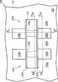
图1是显示一集成电路的一例示的鳍式场效应晶体管的俯视图。FIG. 1 is a top view showing an exemplary FinFET of an integrated circuit.
图2A是显示沿着图1所示的集成电路100的剖面线2A-2A的剖面图。FIG. 2A is a cross-sectional view of the integrated
图2B是显示沿着图1所示的集成电路100的剖面线2B-2B的剖面图。FIG. 2B is a cross-sectional view showing the integrated
图2C是显示沿着图1所示的集成电路100的剖面线2C-2C的剖面图。FIG. 2C is a cross-sectional view showing the integrated
图3是显示一例示的鳍式场效应晶体管的应力与距离(d)的关系的模拟结果的曲线图。FIG. 3 is a graph showing simulation results of stress versus distance (d) for an exemplary FinFET.
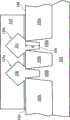
图4是显示具有基底的一部分与隔离区的另一个例示的鳍式场效应晶体管的放大的剖面图。4 is an enlarged cross-sectional view showing another exemplary FinFET having a portion of a substrate and an isolation region.
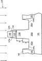
图5A~图5D是一系列的沿着图1的剖面线2C-2C的剖面图,是显示图1所示的鳍式场效应晶体管的一例示的形成方法。5A to 5D are a series of cross-sectional views along the
图6是图示一例示的鳍式场效应晶体管的一例示的形成方法。FIG. 6 is a diagram illustrating an exemplary method of forming an exemplary FinFET.
其中,附图标记说明如下:Wherein, the reference signs are explained as follows:
A~曲线 B~曲线A~curve B~curve
d~距离 h~高度d~distance h~height
2A~剖面线 2B~剖面线2A~hatching line 2B~hatching line
2C~剖面线 100~集成电路2C~
101~基底 102a~部分101~
102b~部分 102c~部分102b~
102d~部分 102e~部分102d~
103~隔离结构 103a~隔离区103~
103b~隔离区 103c~隔离区103b~
104~界面 105a~鳍式场效应晶体管104~
105b~鳍式场效应晶体管 106~表面105b~fin
107~间隔物层 107a~间隔物107~
107b~间隔物 107c~间隔物107b~
107d~间隔物 110a~鳍式沟道本体107d~
110b~鳍式沟道本体 115~栅极110b~
120a~源/漏极区 120b~源/漏极区120a~source/drain
121~外延生长区 123~外延生长区121~
125a~源/漏极区 125b~源/漏极区125a~source/drain
126~外延生长区 130~栅介电质126~
135~鳍状物 140~硬掩模层135 ~ fins 140 ~ hard mask layer
145~移除工艺 145a~表面145~
145b~表面 401~基底145b~surface 401~base
402a~部分 403a~隔离区402a~partial 403a~quarantine area
403b~隔离区 404~表面403b~Quarantine Area 404~Surface
406~表面 408~角落406~surface 408~corner
409~界面 411~尖端409~Interface 411~Advanced
421~外延生长区 610~工艺421~
620~工艺 630~工艺620~
具体实施方式Detailed ways
为让本发明的上述和其他目的、特征、和优点能更明显易懂,下文特举出较佳实施例,并配合附图,作详细说明如下:In order to make the above and other purposes, features, and advantages of the present invention more comprehensible, the preferred embodiments are specifically listed below, together with the accompanying drawings, and are described in detail as follows:
一传统的鳍式场效应晶体管装置是使用从半导体基板竖起的一硅的鳍状物来制造。此装置的沟道区是形成于上述鳍状物中,而将一栅极覆盖(例如围绕)上述鳍状物,例如接触上述鳍状物的上表面与侧壁。围绕沟道区(也就是鳍状物)的优点在于可以从三侧来控制此沟道区。源/漏极区是形成于此鳍状物的二侧。A conventional FinFET device is fabricated using a silicon fin rising from a semiconductor substrate. The channel region of the device is formed in the fin, and a gate covers (eg surrounds) the fin, eg contacts the top surface and sidewalls of the fin. The advantage of surrounding the channel region (ie the fin) is that it can be controlled from three sides. Source/drain regions are formed on both sides of the fin.
要了解的是本说明书以下的公开内容提供许多不同的实施例或范例,以实施本发明的不同特征。而本说明书以下的公开内容是叙述各个构件及其排列方式的特定范例,以求简化发明的说明。当然,这些特定的范例并非用以限定本发明。例如,若是本说明书以下的公开内容叙述了将一第一特征形成于一第一特征之上或上方,即表示其包含了所形成的上述第一特征与上述第二特征是直接接触的实施例,亦包含了尚可将附加的特征形成于上述第一特征与上述第二特征之间,而使上述第一特征与上述第二特征可能未直接接触的实施例。另外,本说明书以下的公开内容可能在各个范例中使用重复的元件符号,以使说明内容更加简化、明确,但是重复的元件符号本身不会使不同的实施例及/或结构之间产生关联。It is to be appreciated that the following disclosure of this specification provides many different embodiments, or examples, for implementing the various features of the invention. However, the following disclosures in this specification describe specific examples of each component and its arrangement in order to simplify the description of the invention. Of course, these specific examples are not intended to limit the present invention. For example, if the following disclosure in this specification describes that a first feature is formed on or over a first feature, it means that it includes the embodiment in which the above-mentioned first feature and the above-mentioned second feature are formed in direct contact , also includes an embodiment in which additional features may be formed between the above-mentioned first feature and the above-mentioned second feature, so that the above-mentioned first feature and the above-mentioned second feature may not be in direct contact. In addition, the following disclosures in this specification may use repeated reference numerals in various examples to simplify and clarify the description, but the repeated reference numerals themselves will not cause association between different embodiments and/or structures.
图1是显示一集成电路的一例示的鳍式场效应晶体管的俯视图。在图1中,一集成电路100可包含至少一个鳍式场效应晶体管,例如鳍式场效应晶体管105a与105b。鳍式场效应晶体管105a与105b可在一基底101的上方各具有一鳍式沟道本体,例如分别为鳍式沟道本体110a与110b。一栅极115可置于鳍式沟道本体110a与110b的上方。至少一源/漏极区例如为源/漏极区120a-120b与125a-125b,是分别邻接于鳍式沟道本体110a与110b。源/漏极区120a与120b的至少一个是实质上未包含任何鳍式结构。FIG. 1 is a top view showing an exemplary FinFET of an integrated circuit. In FIG. 1, an
请注意鳍式沟道本体110a与110b是位于栅极115的下方,而无法从鳍式场效应晶体管105a与105b的俯视图看到鳍式沟道本体110a与110b。因此,在图1中是以虚线来标示鳍式沟道本体110a与110b,已显示其在鳍式场效应晶体管105a与105b中的位置。Please note that the
在某些实施例中,鳍式沟道本体110a是指具有一鳍状结构的物体,且仅用于在源/漏极区120a与120b之间作为沟道区;在某些其他实施例中,鳍式沟道本体110a可具有一鳍状物体,其仅被栅极115所覆盖;在另外的其他实施例中,鳍式沟道本体110a可具有一鳍状物体,其仅被栅极115及在栅极115的侧壁上的间隔物107a与107b所覆盖。In some embodiments, the
在某些实施例中,基底101可包含一元素半导体,其包含结晶形式、多晶形式、或非晶质结构的硅或锗;或可包含一化合物半导体,其包含碳化硅、砷化镓、磷化镓、磷化铟、砷化铟、或锑化铟;或可包含一合金半导体,其包含SiGe、GaAsP、AlInAs、AlGaAs、GaInAs、GaInP、或GaInAsP;或可包含其他适当的材料;或上述的组合。在一实施例中,上述合金半导体基底可具有一渐变的SiGe结构,其中硅与锗的成分是从在上述渐变的SiGe结构的某个位置的比例变成在上述渐变的SiGe结构的另一个位置的另一个比例;在另一个实施例中,上述合金SiGe是位于硅基底的上方;在又另一个实施例中,一SiGe基底是受到应变。另外,上述半导体基底可以是绝缘体上覆半导体,例如是绝缘体上覆硅(silicon on insulator;SOI)、或一薄膜晶体管(thinfilm transistor;TFT)。在某些实例中,上述半导体基底可具有一掺杂的外延层或一埋入层;在其他实例中,上述化合物半导体基底可具有一多层结构,或是上述基底可具有一多层的化合物半导体结构。In some embodiments, the
请参考图1,一隔离结构103可包含至少一个隔离区,例如隔离区103a~103c。隔离结构103可围绕鳍式场效应晶体管105a与105b,并电性隔离鳍式场效应晶体管105a与鳍式场效应晶体管105b。隔离结构103可包含一浅沟槽隔离(shallow trench isolation;STI)结构、一硅的局部氧化(localoxidation of silicon;LOCOS)结构、其他的隔离结构、或上述的任意组合。Please refer to FIG. 1 , an
请参考图1,间隔物107a与107b可邻接于栅极115。间隔物107a与107b可适当地将源/漏极区120a、120b、125a、和125b与栅极115隔开。间隔物107a与107b可以各包含至少一材料,例如氧化物、氮化物、氧氮化物、其他介电材料、或上述的任意组合。Referring to FIG. 1 , the
图2A是显示沿着图1所示的集成电路100的剖面线2A-2A的剖面图。在图2A中,基底101可具有至少一个部分,例如部分102a与102b。在某些实施例中,部分102a可置于隔离区103a与103b之间。一栅介电质130可置于栅极115的下方。鳍式沟道本体110a与110b(如图1所示)是分别在源/漏极区120a与125a的背后而被其挡住。FIG. 2A is a cross-sectional view of the
在某些实施例中,栅介电质130可为单层或多层结构。在某些多层结构的实施例中,栅介电质130可包含一界面层与一高介电常数介电层。上述界面层可包含一介电材料,例如氧化硅、氮化硅、氧氮化硅、其它介电材料、及/或上述的组合。上述高介电常数介电层可包含高介电常数的介电材料,例如HfO2、HfSiO、HfSiON、HfTaO、HfTiO、HfZrO、其他适当的高介电常数介电材料、及/或上述的组合。上述高介电常数介电材料还可选自金属氧化物、金属氮化物、金属硅酸盐、过渡金属氧化物、过渡金属氮化物、过渡金属硅酸盐、金属的氧氮化物、金属铝酸盐、硅酸锆、铝酸锆、氧化硅、氮化硅、氧氮化硅、氧化锆、氧化钛、氧化铝、二氧化铪-氧化铝混合物、其他适当的材料、及/或上述的组合。In some embodiments, the
在某些实施例中,栅极115可包含复晶硅、硅锗(silicon-germanium)、包含金属化合物的金属材料例如铝、钼、铜、钨、钛、钽、氮化钛、氮化钽、NiSi、CoSi、其他本技术领域中已知的适当的导体材料、或上述的任意组合;在其他实施例中,栅极115可包含位于一金属层上方的一复晶硅层;在另外的其他实施例中,栅极115可具有一功函数金属层,而使其作为一金属栅极的一N型金属功函数或P型金属功函数。P型功函数材料的成分包含例如钌、钯、铂、钴、镍、与导体性金属氧化物、及/或其他适当的材料。N型功函数材料的成分包含例如铪、锆、钛、钽、铝、金属碳化物(例如碳化铪、碳化锆、碳化钛、碳化铝)、铝化物(aluminides)、及/或其他适当的材料。In some embodiments, the
在某些实施例中,源/漏极区120a与125a可各包含一外延生长区,例如分别为外延生长区121与126。外延生长区121可置于基底101的部分102a的上方,外延生长区121与部分102a可具有一界面104。在某些实施例中,界面104的一中心区可与隔离区103a的一表面106在实质上同一水平上;在其他实施例中,界面104的中心区可低于隔离区103a的表面106;在另外的其他实施例中,界面104的中心区可与隔离区103a的表面106相隔一距离“d”;在另外的其他实施例中,界面104的中心区可以是实质上平坦的。In some embodiments, each of the source/
在某些实施例中,外延生长区121与126可具有掺杂物。在某些形成N型的鳍式场效应晶体管的实施例中,外延生长区121与126可具有掺杂物例如砷(As)、磷(P)、其他V族元素、或上述的任意组合;在某些形成P型的鳍式场效应晶体管的实施例中,外延生长区121与126可具有掺杂物例如硼(B)、其他III族元素、或上述的任意组合。在某些实施例中,外延生长区121与126可具有一多层结构例如一双层或三层结构。例如一双层结构可包含在一硅顶盖层下方的一硅锗层。In some embodiments, the
在某些实施例中,鳍式场效应晶体管105a与105b可包含置于外延生长区121与126的上方的一硅化物结构(未绘示)。上述硅化物结构可包含的材料例如硅化镍(NiSi)、硅化镍-铂(NiPtSi)、硅化镍-铂-锗(NiPtGeSi)、硅化镍-锗(NiGeSi)、硅化镱(YbSi)、硅化铂(PtSi)、硅化铱(IrSi)、硅化铒(ErSi)、硅化钴(CoSi)、其他适当的材料、及/或上述的组合。In some embodiments, the
图2B是显示沿着图1所示的集成电路100的剖面线2B-2B的剖面图。在图2B中,基底101可包含至少一个部分,例如部分102c与102d,鳍式沟道本体110a则可置于部分102c的上方,鳍式沟道本体110a可具有一高度“h”。部分102c可置于隔离区103a与103b之间,而部分102c可与部分102a(示于图2A)连接。在某些实施例中,鳍式沟道本体110a与部分102c可具有相同材料,例如硅;在其他实施例中,鳍式沟道本体110a与部分102c可具有不同材料,例如分别为硅锗与硅。FIG. 2B is a cross-sectional view showing the
图2C是显示沿着图1所示的集成电路100的剖面线2C-2C的剖面图。在图2C中,外延生长区121与123可分别置于基底101的部分102a与102e上,而鳍式沟道本体110a可置于基底101的部分102c上。如图所示,在某些实施例中,隔离结构103的界面104与表面106可具有一距离“d”,鳍式沟道本体110a可具有一高度“h”。在某些实施例中,距离“d”对于高度“h”的比值(d/h)可以是小于或等于大约10;在至少一实施例中,比值(d/h)约为1。FIG. 2C is a cross-sectional view showing the
请参考图2C,外延生长区121与123可对鳍式沟道本体110a提供一应力,例如压应力或张应力。受到压缩化拉伸的鳍式沟道本体110a可对鳍式场效应晶体管105a提供所需的电子迁移率或空穴迁移率。在提供一压应力的某些实施例中,鳍式沟道本体110a可具有一硅材料,而外延生长区121与123可具有一硅锗材料。在提供一压应力的其他实施例中,鳍式沟道本体110a及外延生长区121与123可具有一硅锗材料,其中外延生长区121与123所具有的锗浓度可大于鳍式沟道本体110a的锗浓度。Referring to FIG. 2C , the
在提供一张应力的某些实施例中,鳍式沟道本体110a可具有一硅材料,而外延生长区121与123可具有一SiC材料。在提供一张应力的其他实施例中,鳍式沟道本体110a及外延生长区121与123可具有一SiC材料,其中外延生长区121与123所具有的碳浓度可大于鳍式沟道本体110a的碳浓度。In some embodiments providing tensile stress, the
图3是显示某些实施例的一例示的鳍式场效应晶体管的应力与距离(d)的关系的模拟结果的曲线图。在图3中,垂直的座标轴是代表作用于一鳍式沟道本体1的一应力,而水平座标轴则代表距离“d”。在此模拟作业中,鳍式沟道本体110a所具有的高度“h”是约40nm,并具有一硅材料。外延生长区121与123可具有锗浓度为36atomic%(原子百分比)的一硅锗材料。一外延硅层(未绘示)是形成于外延生长区121与123的每一个之上。曲线A是代表以一先栅极工艺(gate-first process)来形成鳍式场效应晶体管105a,曲线B是代表以一后栅极工艺(gate-last process)来形成鳍式场效应晶体管105a。3 is a graph showing simulation results of stress versus distance (d) for an exemplary FinFET according to certain embodiments. In FIG. 3 , the vertical axis represents a stress acting on a fin channel body 1 , and the horizontal axis represents distance "d". In this simulation run, the
请再参考图3,在距离“d”为约0的某些实施例中,界面104的中央区是与隔离区103a的表面106实质上在同一个水平,可对以一先栅极工艺与一后栅极工艺所形成的鳍式沟道本体110a分别施加约-400Mpa与-700Mpa的应力。通过增加距离“d”,以一先栅极工艺或一后栅极工艺所形成的鳍式场效应晶体管105a的鳍式沟道本体110a的应力值便增加。在其他的实施例中,如果距离“d”实质上等于或大于高度“h”,施加于鳍式场效应晶体管105a的鳍式沟道本体110a的应力值的增幅可变慢。如前所述,外延生长区121与123是实质上未包含任何鳍式结构。外延生长区121与123的量可对鳍式场效应晶体管105a的鳍式沟道本体110a提供一所需的应力。Please refer to FIG. 3 again. In some embodiments where the distance "d" is about 0, the central region of the
图4是显示具有基底的一部分与隔离区的另一个例示的鳍式场效应晶体管的放大的剖面图。图4所示元件中与图2A所示元件相同者,是以图2A的元件符号在数值上加上300来代表。在某些实施例中,一隔离区403a可具有一角落408,而隔离区403a的一表面406是和隔离区403a与基底401的部分402a之间的一界面409在角落408处交叉。基底401的部分402a具有一尖端411,而基底401的部分402a的一表面404是和隔离区403a与基底401的部分402a之间的界面409在尖端411处交叉。角落408是实质上邻接于尖端411。在某些实施例中,用以形成外延生长区421的一工艺可在一含氢的环境中的一重流工艺。上述重流工艺可使表面404的中心部分变平坦。4 is an enlarged cross-sectional view showing another exemplary FinFET having a portion of a substrate and an isolation region. Components shown in FIG. 4 that are the same as those shown in FIG. 2A are denoted by adding 300 to the component numbers in FIG. 2A . In some embodiments, an isolation region 403 a may have a corner 408 , and a surface 406 of the isolation region 403 a intersects an interface 409 between the isolation region 403 a and the portion 402 a of the substrate 401 at the corner 408 . The portion 402 a of the substrate 401 has a tip 411 , and a surface 404 of the portion 402 a of the substrate 401 intersects the interface 409 between the isolation region 403 a and the portion 402 a of the substrate 401 at the tip 411 . Corner 408 is substantially adjacent to tip 411 . In some embodiments, a process used to form the epitaxial growth region 421 may be a reflow process in a hydrogen-containing environment. The reflow process described above may flatten the central portion of the surface 404 .
我们发现若角落408是实质上邻接于尖端411,可从基底401的部分402a形成一足够量的外延生长区421。外延生长区421的足够的量可对鳍式场效应晶体管的鳍式沟道本体提供一应力。外延生长区421的量亦可减少源/漏极区的电阻。在某些实施例中,通过一同步掺杂的工艺(in-situ doped process)而在外延生长区421添加掺杂物,可进一步地减少源/漏极区的电阻。We have found that if corner 408 is substantially adjacent to tip 411, a sufficient amount of epitaxially grown region 421 can be formed from portion 402a of substrate 401. A sufficient amount of the epitaxial growth region 421 can provide a stress to the fin channel body of the fin field effect transistor. The amount of epitaxial growth region 421 can also reduce the resistance of the source/drain region. In some embodiments, adding dopants to the epitaxial growth region 421 through an in-situ doped process can further reduce the resistance of the source/drain region.
图5A~图5D是一系列的沿着图1的剖面线2C-2C的剖面图,是显示图1所示的鳍式场效应晶体管的一例示的形成方法。在图5A中,可以在基底101中及/或上方形成隔离结构103,并可在基底101的上方形成一鳍状物135,鳍状物135可具有一高度“h”。可以在鳍状物135的上方形成栅介电质130与栅极115。可以在栅极115的上方形成一硬掩模层140。可形成一间隔物层107,其顺应性地位在鳍状物135、硬掩模层140、与栅极115及栅介电质130的侧壁的上方。可通过包含例如沉积工艺、蚀刻工艺、清洁工艺、光刻工艺、及/或上述的任意组合的多道工艺,来形成隔离结构103、栅介电质130、栅极115、间隔物层107、鳍状物135、及/或硬掩模层140。5A to 5D are a series of cross-sectional views along the
请参考图5B,可移除间隔物层107(绘示于图5A)的一些部分,以形成间隔物107a~107d。间隔物107a与107b可形成于栅极115的侧壁上,而间隔物107c与107d可形成于鳍状物135的侧壁上。在某些实施例中,间隔物107a与107b可覆盖栅极115,以避免从栅极115的侧壁作外延生长所造成的一蘑菇效应(mushroom effect)。可通过包含例如沉积工艺、蚀刻工艺、清洁工艺、光刻工艺、及/或上述的任意组合的多道工艺,来形成隔离结构103、栅介电质130、栅极115、间隔物107a与107b、鳍状物135、及/或硬掩模层140。Referring to FIG. 5B , some parts of the spacer layer 107 (shown in FIG. 5A ) may be removed to form
请参考图5C,一移除工艺145可移除鳍状物135的至少一部分,以暴露基底101的部分102a的表面145a与基底101的部分102e的表面145b,并定义鳍式沟道本体110a。移除工艺145亦可移除间隔物107c与107d。在某些实施例中,移除工艺145可实质上移除鳍状物135的上述部分,而使暴露的表面145a的一中心区可实质上与隔离结构103的表面106在同一水平面;在其他实施例中,移除工艺145可移除基底101的一部分,以使暴露的表面145a的上述中心区可低于在隔离结构103的表面106。距离“d”可定义为暴露的表面145a与隔离结构103的表面106之间的距离。距离“d”对于高度“h”的比值(d/h)可小于或等于约10。在至少一实施例中,比值(d/h)可约为1。Referring to FIG. 5C , a
在某些实施例中,前文所述与图5A~图5C相关的工艺步骤,可作为在基板101的上方形成鳍式沟道本体110a、与在鳍式沟道本体110a的上方形成栅极115(图6所示的工艺610与620)的工艺。在其他实施例中,工艺610可包含用以形成鳍式沟道本体110a的一或多个的已知的半导体工艺步骤。在另外的其他实施例中,可节省前文所述与图5A~图5C相关的一或多道的工艺步骤,以执行工艺610与620。In some embodiments, the aforementioned process steps related to FIG. 5A to FIG. 5C can be used as forming the
请参考图5D,可形成邻接于鳍式沟道本体110a的至少一源/漏极区,例如源/漏极区120a与120b。在某些实施例中,源/漏极区120a与120b的形成可包含从基底101的部分102a的暴露的表面145a与基底101的部分102e的暴露的表面145b,分别外延生长出外延生长区121与123。在某些实施例中,外延生长区121与123可各具有一(100)刻面(facet)。Referring to FIG. 5D , at least one source/drain region, such as source/
在某些实施例中,前文所述与图5A~图5D相关的工艺步骤,可作为形成邻接于上述鳍式沟道本体的至少一源/漏极区的一工艺,其中上述至少一源/漏极区是实质上未包含任何鳍式结构(图6中所示的工艺630)。In some embodiments, the aforementioned process steps related to FIGS. 5A to 5D can be used as a process for forming at least one source/drain region adjacent to the fin channel body, wherein the at least one source/drain region The drain region is substantially free of any fin structures (
在某些实施例中,鳍式场效应晶体管105a的形成方法可包含在源/漏极区120a与120b中注入掺杂物。对于形成N型沟道区的存储单元的实施例,源/漏极区120a与120b可具有掺杂物例如砷(As)、磷(P)、其他V族元素、或上述的任意组合。In some embodiments, the forming method of the
在其他实施例中,鳍式场效应晶体管105a的形成方法可包含在外延生长区121与123的至少一部分沉积硅化金属,外延生长区121与123的硅化物可提供所需的传导性。上述硅化物可包含的材料例如硅化镍(NiSi)、硅化镍-铂(NiPtSi)、硅化镍-铂-锗(NiPtGeSi)、硅化镍-锗(NiGeSi)、硅化镱(YbSi)、硅化铂(PtSi)、硅化铱(IrSi)、硅化铒(ErSi)、硅化钴(CoSi)、其他适当的材料、及/或上述的组合。用来产生上述硅化物的材料可使用下列方法来进行沉积:物理气相沉积法(physical vapor deposition;PVD),例如溅镀(sputtering)与蒸镀(evaporation);镀膜法(plating);化学气相沉积法(chemical vapor deposition;CVD),例如等离子体增益化学气相沉积法(plasma enhanced chemical vapordeposition;PECVD)、常压化学气相沉积法(atmospheric pressure chemicalvapor deposition;APCVD)、低压化学气相沉积法(low pressure chemical vapordeposition;LPCVD)、高密度等离子体化学气相沉积法(high density plasmachemical vapor deposition;HDPCVD)与原子级层化学气相沉积法(atomic layerchemical vapor deposition;ALCVD);其他适当的沉积工艺;及/或上述的组合。在沉积之后,可继续进行硅化金属沉积工艺,而在较高的温度之下使被沉积的物质与上述掺杂区发生反应,而上述温度的选择是根据所选用的特定材料而定,此步骤亦称之为退火,其可包含一快速热工艺(Rapid ThermalProcess;RTP)。上述已反应的硅化物可能需要单一步骤的快速热工艺或多重步骤的快速热工艺。In other embodiments, the forming method of the
在某些实施例中,鳍式场效应晶体管105a的形成方法可包含在每个外延生长区121与123的上方形成一外延层(未绘示),例如一硅外延层。在形成上述硅外延层之后,上述方法可包含在上述外延层的至少一部分沉积硅化金属。我们发现从上述硅外延层形成硅化物可以令人满意地减低上述硅化物的缺陷,而可以达成具有所需的传导性的硅化物。In some embodiments, the forming method of the
在其他实施例中,鳍式场效应晶体管105a的形成方法可包含一蚀刻工艺(未绘示),以移除基底101的一部分。上述蚀刻工艺可包含例如一干蚀刻工艺、一湿蚀刻工艺、及/或上述的组合。可以在前文所述与图5C相关的移除工艺145之后、及/或在前文所述与图5D相关的形成外延生长区121与123的步骤之前,来执行上述蚀刻工艺。再某些实施例中,在移除工艺145之后,隔离结构103的一上角落可能会高于基底101的部分102a的一尖端。上述蚀刻工艺可移除基底101的一部分,而使隔离结构103的一上角落实质上邻接于基底101的部分102a的一尖端,如前文所述与图4相关的部分。上述实质上在同一水平上的角落与尖端可以使得从已暴露的表面145a与145b,分别形成令人满意的量的外延生长区121与123。外延生长区121与123的令人满意的量,可对鳍式沟道本体110a提供所需的应力。In other embodiments, the forming method of the
在另外的其他实施例中,鳍式场效应晶体管105a的形成方法可包含使基底101的已暴露的表面145a与145b重流(reflow),以使基底101的已暴露的表面145a与145b的中心区成为实质上平坦的。已暴露的表面145a与145b的实质上平坦的中心区,可以使得外延生长区121与123令人满意地分别从已暴露的表面145a与145b形成。在某些实施例中,可以在一含氢的环境中执行已暴露的表面145a与145b的重流,其工艺温度为约600℃~800℃、持续约30分钟。In yet other embodiments, the method of forming the
在某些实施例中,可以在上述基底的上方形成至少一介电结构(未绘示)。上述介电结构可包含材料例如氧化物、氮化物、氧氮化物、低介电常数介电材料、超低介电常数介电材料(ultra low-k dielectric material)、或上述的任意组合。可通过例如一化学气相沉积工艺、一高密度等离子体化学气相沉积工艺、一高纵深比填沟工艺(high aspect ratio process;HARP)、其他的沉积工艺、及/或上述的任意组合。In some embodiments, at least one dielectric structure (not shown) may be formed above the substrate. The above-mentioned dielectric structure may include materials such as oxides, nitrides, oxynitrides, low-k dielectric materials, ultra low-k dielectric materials, or any combination thereof. For example, a chemical vapor deposition process, a high-density plasma chemical vapor deposition process, a high aspect ratio trench filling process (high aspect ratio process; HARP), other deposition processes, and/or any combination thereof may be used.
在某些实施例中,可以在上述介电结构中形成接触插塞(contact plugs)、介层插塞(via plugs)、金属区、及/或金属线,以作为内连线。上述接触插塞、介层插塞、金属区、及/或金属线可包含材料例如钨、铝、铜、钛、钽、氮化钛、氮化钽、硅化镍、硅化钴、其他适当地导体材料、及/或上述的组合。可通过任何适当的工艺来形成上述接触插塞、介层插塞、金属区、及/或金属线,例如沉积、光刻、与蚀刻工艺、及/或上述的组合。请注意前文所述与图5A~图5D相关的方法仅为举例,其方法可以是一先栅极工艺或一后栅极工艺,但本发明的范围并不限于此。In some embodiments, contact plugs, via plugs, metal regions, and/or metal lines may be formed in the above-mentioned dielectric structures as interconnects. The contact plugs, via plugs, metal regions, and/or metal lines may comprise materials such as tungsten, aluminum, copper, titanium, tantalum, titanium nitride, tantalum nitride, nickel silicide, cobalt silicide, and other suitable conductors. materials, and/or combinations of the above. The above-mentioned contact plugs, via plugs, metal regions, and/or metal lines may be formed by any suitable process, such as deposition, photolithography, and etching processes, and/or combinations thereof. Please note that the aforementioned method related to FIG. 5A-FIG. 5D is just an example, and the method may be a gate-first process or a gate-last process, but the scope of the present invention is not limited thereto.
在某些实施例中,鳍式场效应晶体管105a及/或105b可在一封装体内形成,此封装体可结构性与电性连接于一印刷线路板或一印刷电路板(printedcircuit board;PCB),已形成一电子组装体。此电子组装体可以是例如计算机、无线通信装置、计算机相关周边设备、娱乐器材、或同类装置等的一电子系统的一部分。In some embodiments, the
在某些实施例中,包含集成电路100的上述系统,可在一个集成电路中提供一整套的系统,即是所谓的系统整合芯片(system on a chip;SOC)装置或系统整合集成电路(system on integrated circuit;SOIC)装置。这些系统整合芯片装置可在单一的集成电路中,提供用以发挥一移动电话、个人数字助理(personal data assistant;PDA)、数字卡式录放影机(digital VCR)、数字摄录象机(digital camcorder)、数字相机、MP3播放器、或类似装置的功能所需的所有电路系统。In some embodiments, the above-mentioned system including the integrated
虽然本发明已以较佳实施例公开如上,然其并非用以限定本发明,任何本发明所属技术领域中的普通技术人员,在不脱离本发明的精神和范围内,当可作些许的更动与润饰,因此本发明的保护范围当视随附的权利要求所界定的保护范围为准。Although the present invention has been disclosed as above with preferred embodiments, it is not intended to limit the present invention, and any ordinary skilled person in the technical field to which the present invention belongs can make some modifications without departing from the spirit and scope of the present invention. Therefore, the scope of protection of the present invention should be determined by the scope of protection defined by the appended claims.
Claims (7)
Applications Claiming Priority (4)
| Application Number | Priority Date | Filing Date | Title |
|---|---|---|---|
| US24775609P | 2009-10-01 | 2009-10-01 | |
| US61/247,756 | 2009-10-01 | ||
| US12/761,686US8264021B2 (en) | 2009-10-01 | 2010-04-16 | Finfets and methods for forming the same |
| US12/761,686 | 2010-04-16 |
Publications (2)
| Publication Number | Publication Date |
|---|---|
| CN102034871A CN102034871A (en) | 2011-04-27 |
| CN102034871Btrue CN102034871B (en) | 2013-10-02 |
Family
ID=43822531
Family Applications (1)
| Application Number | Title | Priority Date | Filing Date |
|---|---|---|---|
| CN201010501836.1AActiveCN102034871B (en) | 2009-10-01 | 2010-09-30 | Fin field effect transistor and method of forming the same |
Country Status (5)
| Country | Link |
|---|---|
| US (1) | US8264021B2 (en) |
| JP (1) | JP5595856B2 (en) |
| KR (1) | KR101217327B1 (en) |
| CN (1) | CN102034871B (en) |
| TW (1) | TWI456760B (en) |
Families Citing this family (90)
| Publication number | Priority date | Publication date | Assignee | Title |
|---|---|---|---|---|
| US8440517B2 (en)* | 2010-10-13 | 2013-05-14 | Taiwan Semiconductor Manufacturing Company, Ltd. | FinFET and method of fabricating the same |
| US8362572B2 (en)* | 2010-02-09 | 2013-01-29 | Taiwan Semiconductor Manufacturing Co., Ltd. | Lower parasitic capacitance FinFET |
| US8653610B2 (en)* | 2010-04-21 | 2014-02-18 | International Business Machines Corporation | High performance non-planar semiconductor devices with metal filled inter-fin gaps |
| US8729627B2 (en)* | 2010-05-14 | 2014-05-20 | Taiwan Semiconductor Manufacturing Company, Ltd. | Strained channel integrated circuit devices |
| US8361853B2 (en) | 2010-10-12 | 2013-01-29 | International Business Machines Corporation | Graphene nanoribbons, method of fabrication and their use in electronic devices |
| US8642996B2 (en)* | 2011-04-18 | 2014-02-04 | International Business Machines Corporation | Graphene nanoribbons and carbon nanotubes fabricated from SiC fins or nanowire templates |
| CN103021854B (en)* | 2011-09-28 | 2015-09-16 | 中国科学院微电子研究所 | Method for manufacturing fin field effect transistor and semiconductor structure formed by method |
| US9893163B2 (en) | 2011-11-04 | 2018-02-13 | Taiwan Semiconductor Manufacturing Company, Ltd. | 3D capacitor and method of manufacturing same |
| US8603915B2 (en) | 2011-11-28 | 2013-12-10 | International Business Machines Corporation | Multi-stage silicidation process |
| KR101700213B1 (en)* | 2011-12-21 | 2017-01-26 | 인텔 코포레이션 | Methods for forming fins for metal oxide semiconductor device structures |
| WO2013095550A1 (en)* | 2011-12-22 | 2013-06-27 | Intel Corporation | Semiconductor device having a necked semiconductor body and method of forming semiconductor bodies of varying width |
| US9236476B2 (en) | 2011-12-28 | 2016-01-12 | Intel Corporation | Techniques and configuration for stacking transistors of an integrated circuit device |
| US8486770B1 (en) | 2011-12-30 | 2013-07-16 | Taiwan Semiconductor Manufacturing Company, Ltd. | Method of forming CMOS FinFET device |
| US8377779B1 (en) | 2012-01-03 | 2013-02-19 | Taiwan Semiconductor Manufacturing Company, Ltd. | Methods of manufacturing semiconductor devices and transistors |
| US8759184B2 (en)* | 2012-01-09 | 2014-06-24 | Taiwan Semiconductor Manufacturing Company, Ltd. | FinFETs and the methods for forming the same |
| US8609499B2 (en) | 2012-01-09 | 2013-12-17 | Taiwan Semiconductor Manufacturing Company, Ltd. | FinFETs and the methods for forming the same |
| US8659032B2 (en)* | 2012-01-31 | 2014-02-25 | Taiwan Semiconductor Manufacturing Company, Ltd. | FinFET and method of fabricating the same |
| US8664060B2 (en) | 2012-02-07 | 2014-03-04 | United Microelectronics Corp. | Semiconductor structure and method of fabricating the same |
| KR101876793B1 (en)* | 2012-02-27 | 2018-07-11 | 삼성전자주식회사 | Field Effect Transistor and Method of fabricating the same |
| US9368388B2 (en)* | 2012-04-13 | 2016-06-14 | Taiwan Semiconductor Manufacturing Company, Ltd. | Apparatus for FinFETs |
| US9171929B2 (en) | 2012-04-25 | 2015-10-27 | Taiwan Semiconductor Manufacturing Company, Ltd. | Strained structure of semiconductor device and method of making the strained structure |
| US8669147B2 (en) | 2012-06-11 | 2014-03-11 | Globalfoundries Inc. | Methods of forming high mobility fin channels on three dimensional semiconductor devices |
| US8492228B1 (en) | 2012-07-12 | 2013-07-23 | International Business Machines Corporation | Field effect transistor devices having thick gate dielectric layers and thin gate dielectric layers |
| US9142400B1 (en) | 2012-07-17 | 2015-09-22 | Stc.Unm | Method of making a heteroepitaxial layer on a seed area |
| CN103579295B (en)* | 2012-07-25 | 2016-12-28 | 中国科学院微电子研究所 | Semiconductor device and method for manufacturing the same |
| US9136383B2 (en)* | 2012-08-09 | 2015-09-15 | Taiwan Semiconductor Manufacturing Company, Ltd. | Contact structure of semiconductor device |
| US9105490B2 (en)* | 2012-09-27 | 2015-08-11 | Taiwan Semiconductor Manufacturing Company, Ltd. | Contact structure of semiconductor device |
| US9287138B2 (en) | 2012-09-27 | 2016-03-15 | Taiwan Semiconductor Manufacturing Company, Ltd. | FinFET low resistivity contact formation method |
| US8823065B2 (en) | 2012-11-08 | 2014-09-02 | Taiwan Semiconductor Manufacturing Company, Ltd. | Contact structure of semiconductor device |
| US8716803B2 (en)* | 2012-10-04 | 2014-05-06 | Flashsilicon Incorporation | 3-D single floating gate non-volatile memory device |
| US8809139B2 (en) | 2012-11-29 | 2014-08-19 | Taiwan Semiconductor Manufacturing Company, Ltd. | Fin-last FinFET and methods of forming same |
| CN103928328B (en)* | 2013-01-10 | 2016-12-28 | 中芯国际集成电路制造(上海)有限公司 | The forming method of fin formula field effect transistor |
| KR102049774B1 (en) | 2013-01-24 | 2019-11-28 | 삼성전자 주식회사 | Semiconductor device and fabricated method thereof |
| TWI499044B (en)* | 2013-01-25 | 2015-09-01 | Flashsilicon Inc | 3-d single floating gate non-volatile memory device |
| US9196709B2 (en)* | 2013-02-01 | 2015-11-24 | Taiwan Semiconductor Manufacturing Company, Ltd. | Methods for forming semiconductor regions in trenches |
| US9123633B2 (en) | 2013-02-01 | 2015-09-01 | Taiwan Semiconductor Manufacturing Company, Ltd. | Methods for forming semiconductor regions in trenches |
| US9166053B2 (en)* | 2013-02-22 | 2015-10-20 | Taiwan Semiconductor Manufacturing Company, Ltd. | FinFET device including a stepped profile structure |
| US9209066B2 (en)* | 2013-03-01 | 2015-12-08 | Taiwan Semiconductor Manufacturing Company, Ltd. | Isolation structure of semiconductor device |
| US9831345B2 (en) | 2013-03-11 | 2017-11-28 | Taiwan Semiconductor Manufacturing Company, Ltd. | FinFET with rounded source/drain profile |
| KR102042476B1 (en)* | 2013-03-14 | 2019-11-08 | 인텔 코포레이션 | Leakage reduction structures for nanowire transistors |
| KR102045212B1 (en) | 2013-04-23 | 2019-11-15 | 삼성전자 주식회사 | Semiconductor device and fabricated method thereof |
| US9006066B2 (en) | 2013-04-26 | 2015-04-14 | Globalfoundries Inc. | FinFET with active region shaped structures and channel separation |
| CN105531797A (en)* | 2013-06-28 | 2016-04-27 | 英特尔公司 | Nanostructures and nanofeatures with Si(111) planes on Si(100) wafers for III-N epitaxy |
| US20150024584A1 (en)* | 2013-07-17 | 2015-01-22 | Global Foundries, Inc. | Methods for forming integrated circuits with reduced replacement metal gate height variability |
| US9293587B2 (en) | 2013-07-23 | 2016-03-22 | Globalfoundries Inc. | Forming embedded source and drain regions to prevent bottom leakage in a dielectrically isolated fin field effect transistor (FinFET) device |
| US9059002B2 (en)* | 2013-08-27 | 2015-06-16 | International Business Machines Corporation | Non-merged epitaxially grown MOSFET devices |
| US9112030B2 (en)* | 2013-11-04 | 2015-08-18 | United Microelectronics Corp. | Epitaxial structure and process thereof for non-planar transistor |
| KR102175854B1 (en) | 2013-11-14 | 2020-11-09 | 삼성전자주식회사 | Semiconductor device and method of manufacturing the same |
| KR102105363B1 (en) | 2013-11-21 | 2020-04-28 | 삼성전자 주식회사 | Semiconductor device and fabricating method thereof |
| KR102085525B1 (en) | 2013-11-27 | 2020-03-09 | 삼성전자 주식회사 | Semiconductor device and method for fabricating the same |
| CN104733312B (en)* | 2013-12-18 | 2018-09-07 | 中芯国际集成电路制造(上海)有限公司 | The forming method of fin formula field effect transistor |
| US9472652B2 (en)* | 2013-12-20 | 2016-10-18 | Taiwan Semiconductor Manufacturing Company, Ltd. | Fin structure of semiconductor device |
| US9853154B2 (en) | 2014-01-24 | 2017-12-26 | Taiwan Semiconductor Manufacturing Company Ltd. | Embedded source or drain region of transistor with downward tapered region under facet region |
| US10164107B2 (en) | 2014-01-24 | 2018-12-25 | Taiwan Semiconductor Manufacturing Company Ltd. | Embedded source or drain region of transistor with laterally extended portion |
| KR102151768B1 (en)* | 2014-01-27 | 2020-09-03 | 삼성전자주식회사 | Semiconductor device and method of manufacturing the same |
| KR102155181B1 (en) | 2014-01-28 | 2020-09-11 | 삼성전자주식회사 | Semiconductor devices and methods of manufacturing the same |
| US20150214331A1 (en)* | 2014-01-30 | 2015-07-30 | Globalfoundries Inc. | Replacement metal gate including dielectric gate material |
| KR102193493B1 (en) | 2014-02-03 | 2020-12-21 | 삼성전자주식회사 | Semiconductor devices and methods of manufacturing the same |
| JP6361180B2 (en)* | 2014-03-10 | 2018-07-25 | 富士通セミコンダクター株式会社 | Manufacturing method of semiconductor device |
| US9773869B2 (en)* | 2014-03-12 | 2017-09-26 | Samsung Electronics Co., Ltd. | Semiconductor device and method of fabricating the same |
| EP3123521A4 (en) | 2014-03-27 | 2017-10-25 | Intel Corporation | Confined epitaxial regions for semiconductor devices and methods of fabricating semiconductor devices having confined epitaxial regions |
| KR102208063B1 (en) | 2014-04-22 | 2021-01-27 | 삼성전자주식회사 | Semiconductor device and method for fabricating the same |
| KR102200345B1 (en) | 2014-06-26 | 2021-01-11 | 삼성전자주식회사 | Semiconductor device and method of manufacturing the same |
| US10164115B2 (en) | 2014-06-27 | 2018-12-25 | Intel Corporation | Non-linear fin-based devices |
| TWI615976B (en)* | 2014-07-07 | 2018-02-21 | 聯華電子股份有限公司 | Fin field effect transistor and manufacturing method thereof |
| US9543167B2 (en) | 2014-07-15 | 2017-01-10 | Globalfoundries Inc. | FinFET source-drain merged by silicide-based material |
| US9595524B2 (en) | 2014-07-15 | 2017-03-14 | Globalfoundries Inc. | FinFET source-drain merged by silicide-based material |
| KR102219295B1 (en) | 2014-07-25 | 2021-02-23 | 삼성전자 주식회사 | Semiconductor device and method for manufacturing the same |
| KR102265956B1 (en) | 2014-09-29 | 2021-06-17 | 삼성전자주식회사 | Semiconductor devices having a source/drain and Method for fabricating the same |
| US10297673B2 (en)* | 2014-10-08 | 2019-05-21 | Samsung Electronics Co., Ltd. | Methods of forming semiconductor devices including conductive contacts on source/drains |
| US9484346B2 (en)* | 2014-10-15 | 2016-11-01 | Taiwan Semiconductor Manufacturing Company Ltd | Semiconductor structure and manufacturing method thereof |
| US10164108B2 (en) | 2014-10-17 | 2018-12-25 | Taiwan Semiconductor Manufacturing Co., Ltd. | Fin field effect transistor (FinFET) device and method for forming the same |
| KR102217246B1 (en)* | 2014-11-12 | 2021-02-18 | 삼성전자주식회사 | Integrated circuit device and method of manufacturing the same |
| US10269981B2 (en) | 2014-11-17 | 2019-04-23 | Taiwan Semiconductor Manufacturing Company, Ltd. | Multi-channel field effect transistors using 2D-material |
| US9324623B1 (en)* | 2014-11-26 | 2016-04-26 | Samsung Electronics Co., Ltd. | Method of manufacturing semiconductor device having active fins |
| US9472470B2 (en) | 2014-12-09 | 2016-10-18 | GlobalFoundries, Inc. | Methods of forming FinFET with wide unmerged source drain EPI |
| US9954107B2 (en) | 2015-05-05 | 2018-04-24 | International Business Machines Corporation | Strained FinFET source drain isolation |
| US9349798B1 (en) | 2015-06-29 | 2016-05-24 | International Business Machines Corporation | CMOS structures with selective tensile strained NFET fins and relaxed PFET fins |
| US9564489B2 (en)* | 2015-06-29 | 2017-02-07 | Taiwan Semiconductor Manufacturing Company, Ltd. | Multiple gate field-effect transistors having oxygen-scavenged gate stack |
| US9455331B1 (en) | 2015-07-10 | 2016-09-27 | International Business Machines Corporation | Method and structure of forming controllable unmerged epitaxial material |
| US9922975B2 (en) | 2015-10-05 | 2018-03-20 | Taiwan Semiconductor Manufacturing Co., Ltd. | Integrated circuit having field-effect trasistors with dielectric fin sidewall structures and manufacturing method thereof |
| US9768178B2 (en) | 2015-11-11 | 2017-09-19 | Taiwan Semiconductor Manufacturing Co., Ltd. | Semiconductor device, static random access memory cell and manufacturing method of semiconductor device |
| KR102523125B1 (en) | 2015-11-27 | 2023-04-20 | 삼성전자주식회사 | Semiconductor device |
| US10038095B2 (en) | 2016-01-28 | 2018-07-31 | Taiwan Semiconductor Manufacturing Co., Ltd. | V-shape recess profile for embedded source/drain epitaxy |
| US10157748B2 (en)* | 2016-02-08 | 2018-12-18 | Taiwan Semiconductor Manufacturing Co., Ltd. | Fin profile improvement for high performance transistor |
| US10304957B2 (en)* | 2016-09-13 | 2019-05-28 | Qualcomm Incorporated | FinFET with reduced series total resistance |
| KR102360410B1 (en)* | 2017-08-30 | 2022-02-08 | 삼성전자주식회사 | Semiconductor device |
| US10446669B2 (en)* | 2017-11-30 | 2019-10-15 | Taiwan Semiconductor Manufacturing Co., Ltd. | Source and drain surface treatment for multi-gate field effect transistors |
| US10825931B2 (en)* | 2018-02-13 | 2020-11-03 | Nanya Technology Corporation | Semiconductor device with undercutted-gate and method of fabricating the same |
| US11670675B2 (en) | 2020-12-04 | 2023-06-06 | United Semiconductor Japan Co., Ltd. | Semiconductor device |
Citations (3)
| Publication number | Priority date | Publication date | Assignee | Title |
|---|---|---|---|---|
| US6762448B1 (en)* | 2003-04-03 | 2004-07-13 | Advanced Micro Devices, Inc. | FinFET device with multiple fin structures |
| CN1581431A (en)* | 2003-08-14 | 2005-02-16 | 三星电子株式会社 | Multi-structure silicon fin and its making method |
| CN1855539A (en)* | 2005-04-29 | 2006-11-01 | 海力士半导体有限公司 | Transistor structure of memory and manufacturing method thereof |
Family Cites Families (137)
| Publication number | Priority date | Publication date | Assignee | Title |
|---|---|---|---|---|
| JP2833946B2 (en) | 1992-12-08 | 1998-12-09 | 日本電気株式会社 | Etching method and apparatus |
| JP3144967B2 (en) | 1993-11-08 | 2001-03-12 | 株式会社日立製作所 | Semiconductor integrated circuit and method of manufacturing the same |
| KR0146203B1 (en) | 1995-06-26 | 1998-12-01 | 김광호 | Circuit element value adjusting circuit of semiconductor integrated circuit |
| US5963789A (en) | 1996-07-08 | 1999-10-05 | Kabushiki Kaisha Toshiba | Method for silicon island formation |
| US6065481A (en) | 1997-03-26 | 2000-05-23 | Fsi International, Inc. | Direct vapor delivery of enabling chemical for enhanced HF etch process performance |
| TW468273B (en) | 1997-04-10 | 2001-12-11 | Hitachi Ltd | Semiconductor integrated circuit device and method for manufacturing the same |
| JP3660783B2 (en) | 1997-06-30 | 2005-06-15 | 松下電器産業株式会社 | Semiconductor integrated circuit |
| US6740247B1 (en) | 1999-02-05 | 2004-05-25 | Massachusetts Institute Of Technology | HF vapor phase wafer cleaning and oxide etching |
| JP4037029B2 (en)* | 2000-02-21 | 2008-01-23 | 株式会社ルネサステクノロジ | Semiconductor integrated circuit device |
| JP4044721B2 (en) | 2000-08-15 | 2008-02-06 | 株式会社ルネサステクノロジ | Manufacturing method of semiconductor integrated circuit device |
| US6558477B1 (en) | 2000-10-16 | 2003-05-06 | Micron Technology, Inc. | Removal of photoresist through the use of hot deionized water bath, water vapor and ozone gas |
| US6830994B2 (en) | 2001-03-09 | 2004-12-14 | Semiconductor Energy Laboratory Co., Ltd. | Method of manufacturing a semiconductor device having a crystallized semiconductor film |
| US6531412B2 (en) | 2001-08-10 | 2003-03-11 | International Business Machines Corporation | Method for low temperature chemical vapor deposition of low-k films using selected cyclosiloxane and ozone gases for semiconductor applications |
| FR2830984B1 (en) | 2001-10-17 | 2005-02-25 | St Microelectronics Sa | INSULATION TRENCH AND METHOD OF MAKING SAME |
| US6621131B2 (en) | 2001-11-01 | 2003-09-16 | Intel Corporation | Semiconductor transistor having a stressed channel |
| JP4118045B2 (en) | 2001-12-07 | 2008-07-16 | 富士通株式会社 | Semiconductor device |
| US6642090B1 (en) | 2002-06-03 | 2003-11-04 | International Business Machines Corporation | Fin FET devices from bulk semiconductor and method for forming |
| JP2004014737A (en) | 2002-06-06 | 2004-01-15 | Renesas Technology Corp | Semiconductor device and its manufacture |
| US6812103B2 (en) | 2002-06-20 | 2004-11-02 | Micron Technology, Inc. | Methods of fabricating a dielectric plug in MOSFETS to suppress short-channel effects |
| US6974729B2 (en) | 2002-07-16 | 2005-12-13 | Interuniversitair Microelektronica Centrum (Imec) | Integrated semiconductor fin device and a method for manufacturing such device |
| US7358121B2 (en) | 2002-08-23 | 2008-04-15 | Intel Corporation | Tri-gate devices and methods of fabrication |
| JP4031329B2 (en) | 2002-09-19 | 2008-01-09 | 株式会社東芝 | Semiconductor device and manufacturing method thereof |
| US6706571B1 (en) | 2002-10-22 | 2004-03-16 | Advanced Micro Devices, Inc. | Method for forming multiple structures in a semiconductor device |
| US6946373B2 (en) | 2002-11-20 | 2005-09-20 | International Business Machines Corporation | Relaxed, low-defect SGOI for strained Si CMOS applications |
| US7087499B2 (en) | 2002-12-20 | 2006-08-08 | International Business Machines Corporation | Integrated antifuse structure for FINFET and CMOS devices |
| US20040192067A1 (en) | 2003-02-28 | 2004-09-30 | Bruno Ghyselen | Method for forming a relaxed or pseudo-relaxed useful layer on a substrate |
| DE10310740A1 (en) | 2003-03-10 | 2004-09-30 | Forschungszentrum Jülich GmbH | Method for producing a stress-relaxed layer structure on a non-lattice-matched substrate, and use of such a layer system in electronic and / or optoelectronic components |
| US6872647B1 (en) | 2003-05-06 | 2005-03-29 | Advanced Micro Devices, Inc. | Method for forming multiple fins in a semiconductor device |
| US7906441B2 (en) | 2003-05-13 | 2011-03-15 | Texas Instruments Incorporated | System and method for mitigating oxide growth in a gate dielectric |
| TWI242232B (en) | 2003-06-09 | 2005-10-21 | Canon Kk | Semiconductor substrate, semiconductor device, and method of manufacturing the same |
| US7456476B2 (en) | 2003-06-27 | 2008-11-25 | Intel Corporation | Nonplanar semiconductor device with partially or fully wrapped around gate electrode and methods of fabrication |
| US7101742B2 (en) | 2003-08-12 | 2006-09-05 | Taiwan Semiconductor Manufacturing Company, Ltd. | Strained channel complementary field-effect transistors and methods of manufacture |
| US7112495B2 (en) | 2003-08-15 | 2006-09-26 | Taiwan Semiconductor Manufacturing Company, Ltd. | Structure and method of a strained channel transistor and a second semiconductor component in an integrated circuit |
| JP4212435B2 (en) | 2003-08-29 | 2009-01-21 | 株式会社東芝 | Semiconductor device and manufacturing method thereof |
| US7303949B2 (en) | 2003-10-20 | 2007-12-04 | International Business Machines Corporation | High performance stress-enhanced MOSFETs using Si:C and SiGe epitaxial source/drain and method of manufacture |
| KR100585111B1 (en) | 2003-11-24 | 2006-06-01 | 삼성전자주식회사 | Non-planar transistors having germanium channel regions and manufacturing methods thereof |
| KR100513405B1 (en) | 2003-12-16 | 2005-09-09 | 삼성전자주식회사 | Method for forming fin field effect transistor |
| KR100702552B1 (en) | 2003-12-22 | 2007-04-04 | 인터내셔널 비지네스 머신즈 코포레이션 | Automated Layer Creation Method and Device for Double Gate FFT Design |
| KR100552058B1 (en) | 2004-01-06 | 2006-02-20 | 삼성전자주식회사 | Semiconductor device having field effect transistor and manufacturing method thereof |
| KR100587672B1 (en) | 2004-02-02 | 2006-06-08 | 삼성전자주식회사 | Fin transistor formation method using damascene method |
| US6956277B1 (en) | 2004-03-23 | 2005-10-18 | Taiwan Semiconductor Manufacturing Company, Ltd. | Diode junction poly fuse |
| US7154118B2 (en) | 2004-03-31 | 2006-12-26 | Intel Corporation | Bulk non-planar transistor having strained enhanced mobility and methods of fabrication |
| US20050221591A1 (en) | 2004-04-06 | 2005-10-06 | International Business Machines Corporation | Method of forming high-quality relaxed SiGe alloy layers on bulk Si substrates |
| US7300837B2 (en) | 2004-04-30 | 2007-11-27 | Taiwan Semiconductor Manufacturing Co., Ltd | FinFET transistor device on SOI and method of fabrication |
| KR100605104B1 (en) | 2004-05-04 | 2006-07-26 | 삼성전자주식회사 | Fin-Pet device and its manufacturing method |
| JP4493398B2 (en) | 2004-05-13 | 2010-06-30 | 富士通マイクロエレクトロニクス株式会社 | Semiconductor device |
| US7157351B2 (en) | 2004-05-20 | 2007-01-02 | Taiwan Semiconductor Manufacturing Co., Ltd. | Ozone vapor clean method |
| JP4796329B2 (en) | 2004-05-25 | 2011-10-19 | 三星電子株式会社 | Manufacturing method of multi-bridge channel type MOS transistor |
| US7015150B2 (en) | 2004-05-26 | 2006-03-21 | International Business Machines Corporation | Exposed pore sealing post patterning |
| KR100634372B1 (en) | 2004-06-04 | 2006-10-16 | 삼성전자주식회사 | Semiconductor Devices and Formation Methods |
| US7989855B2 (en) | 2004-06-10 | 2011-08-02 | Nec Corporation | Semiconductor device including a deflected part |
| KR100604870B1 (en)* | 2004-06-16 | 2006-07-31 | 삼성전자주식회사 | Field effect transistor and its manufacturing method which can improve the interruption of junction area |
| US7361563B2 (en) | 2004-06-17 | 2008-04-22 | Samsung Electronics Co., Ltd. | Methods of fabricating a semiconductor device using a selective epitaxial growth technique |
| JP5203558B2 (en) | 2004-08-20 | 2013-06-05 | 三星電子株式会社 | Transistor and manufacturing method thereof |
| TWI283066B (en) | 2004-09-07 | 2007-06-21 | Samsung Electronics Co Ltd | Field effect transistor (FET) having wire channels and method of fabricating the same |
| US7067400B2 (en) | 2004-09-17 | 2006-06-27 | International Business Machines Corporation | Method for preventing sidewall consumption during oxidation of SGOI islands |
| BRPI0515714A (en) | 2004-09-27 | 2008-07-29 | Dow Global Technologies Inc | A process for preparing a multilayer coating on the surface of an organic polymeric substrate by atmospheric pressure plasma deposition |
| US7018901B1 (en) | 2004-09-29 | 2006-03-28 | Freescale Semiconductor, Inc. | Method for forming a semiconductor device having a strained channel and a heterojunction source/drain |
| KR100693783B1 (en) | 2004-11-04 | 2007-03-12 | 주식회사 하이닉스반도체 | Internal power generator |
| US7235472B2 (en) | 2004-11-12 | 2007-06-26 | Infineon Technologies Ag | Method of making fully silicided gate electrode |
| US7923339B2 (en) | 2004-12-06 | 2011-04-12 | Nxp B.V. | Method of producing an epitaxial layer on semiconductor substrate and device produced with such a method |
| US7026232B1 (en) | 2004-12-23 | 2006-04-11 | Texas Instruments Incorporated | Systems and methods for low leakage strained-channel transistor |
| US7351662B2 (en)* | 2005-01-07 | 2008-04-01 | Dupont Air Products Nanomaterials Llc | Composition and associated method for catalyzing removal rates of dielectric films during chemical mechanical planarization |
| US20060151808A1 (en) | 2005-01-12 | 2006-07-13 | Chien-Hao Chen | MOSFET device with localized stressor |
| US7282766B2 (en) | 2005-01-17 | 2007-10-16 | Fujitsu Limited | Fin-type semiconductor device with low contact resistance |
| US20080121932A1 (en)* | 2006-09-18 | 2008-05-29 | Pushkar Ranade | Active regions with compatible dielectric layers |
| EP1851789B1 (en) | 2005-02-24 | 2013-05-01 | Soitec | Thermal oxidation of a sige layer and applications thereof |
| JP2006303451A (en) | 2005-03-23 | 2006-11-02 | Renesas Technology Corp | Semiconductor device and manufacturing method of semiconductor device |
| WO2006107942A1 (en) | 2005-04-05 | 2006-10-12 | Analog Devices, Inc. | Vapor hf etch process mask and method |
| JP2006324628A (en) | 2005-05-16 | 2006-11-30 | Interuniv Micro Electronica Centrum Vzw | Method for forming fully silicided gate and device obtained by the method |
| JP4427489B2 (en) | 2005-06-13 | 2010-03-10 | 株式会社東芝 | Manufacturing method of semiconductor device |
| US7547637B2 (en) | 2005-06-21 | 2009-06-16 | Intel Corporation | Methods for patterning a semiconductor film |
| US7960791B2 (en) | 2005-06-24 | 2011-06-14 | International Business Machines Corporation | Dense pitch bulk FinFET process by selective EPI and etch |
| US7279375B2 (en) | 2005-06-30 | 2007-10-09 | Intel Corporation | Block contact architectures for nanoscale channel transistors |
| US7247887B2 (en) | 2005-07-01 | 2007-07-24 | Synopsys, Inc. | Segmented channel MOS transistor |
| US7190050B2 (en) | 2005-07-01 | 2007-03-13 | Synopsys, Inc. | Integrated circuit on corrugated substrate |
| US7265008B2 (en) | 2005-07-01 | 2007-09-04 | Synopsys, Inc. | Method of IC production using corrugated substrate |
| US7807523B2 (en) | 2005-07-01 | 2010-10-05 | Synopsys, Inc. | Sequential selective epitaxial growth |
| US7605449B2 (en) | 2005-07-01 | 2009-10-20 | Synopsys, Inc. | Enhanced segmented channel MOS transistor with high-permittivity dielectric isolation material |
| US8466490B2 (en) | 2005-07-01 | 2013-06-18 | Synopsys, Inc. | Enhanced segmented channel MOS transistor with multi layer regions |
| US7508031B2 (en) | 2005-07-01 | 2009-03-24 | Synopsys, Inc. | Enhanced segmented channel MOS transistor with narrowed base regions |
| EP1744351A3 (en) | 2005-07-11 | 2008-11-26 | Interuniversitair Microelektronica Centrum ( Imec) | Method for forming a fully silicided gate MOSFET and devices obtained thereof |
| JP4774247B2 (en) | 2005-07-21 | 2011-09-14 | Okiセミコンダクタ株式会社 | Voltage regulator |
| KR101172853B1 (en) | 2005-07-22 | 2012-08-10 | 삼성전자주식회사 | Methods of forming semiconductor device |
| JP4749076B2 (en) | 2005-07-27 | 2011-08-17 | ルネサスエレクトロニクス株式会社 | Semiconductor device |
| US20070029576A1 (en) | 2005-08-03 | 2007-02-08 | International Business Machines Corporation | Programmable semiconductor device containing a vertically notched fusible link region and methods of making and using same |
| KR101155097B1 (en) | 2005-08-24 | 2012-06-11 | 삼성전자주식회사 | Fabricating method for semiconductor device and semiconductor device fabricated by the same |
| US7589387B2 (en) | 2005-10-05 | 2009-09-15 | Taiwan Semiconductor Manufacturing Company, Ltd. | SONOS type two-bit FinFET flash memory cell |
| US7425740B2 (en) | 2005-10-07 | 2008-09-16 | Taiwan Semiconductor Manufacturing Company, Ltd. | Method and structure for a 1T-RAM bit cell and macro |
| US8513066B2 (en) | 2005-10-25 | 2013-08-20 | Freescale Semiconductor, Inc. | Method of making an inverted-T channel transistor |
| US7767541B2 (en) | 2005-10-26 | 2010-08-03 | International Business Machines Corporation | Methods for forming germanium-on-insulator semiconductor structures using a porous layer and semiconductor structures formed by these methods |
| DE102005052055B3 (en) | 2005-10-31 | 2007-04-26 | Advanced Micro Devices, Inc., Sunnyvale | Transistor and semiconductor components and production process for thin film silicon on insulator transistor has embedded deformed layer |
| US7525160B2 (en)* | 2005-12-27 | 2009-04-28 | Intel Corporation | Multigate device with recessed strain regions |
| US20070152276A1 (en) | 2005-12-30 | 2007-07-05 | International Business Machines Corporation | High performance CMOS circuits, and methods for fabricating the same |
| US7410844B2 (en) | 2006-01-17 | 2008-08-12 | International Business Machines Corporation | Device fabrication by anisotropic wet etch |
| JP2007194336A (en) | 2006-01-18 | 2007-08-02 | Sumco Corp | Method for manufacturing semiconductor wafer |
| KR100827435B1 (en) | 2006-01-31 | 2008-05-06 | 삼성전자주식회사 | Gate Forming Method Using Oxygen-free Ashing Process in Semiconductor Devices |
| JP2007258485A (en) | 2006-03-23 | 2007-10-04 | Toshiba Corp | Semiconductor device and manufacturing method thereof |
| US7407847B2 (en) | 2006-03-31 | 2008-08-05 | Intel Corporation | Stacked multi-gate transistor design and method of fabrication |
| KR100813527B1 (en) | 2006-04-06 | 2008-03-17 | 주식회사 하이닉스반도체 | Internal voltage generator of semiconductor memory |
| US8076189B2 (en) | 2006-04-11 | 2011-12-13 | Freescale Semiconductor, Inc. | Method of forming a semiconductor device and semiconductor device |
| DE602007000665D1 (en) | 2006-06-12 | 2009-04-23 | St Microelectronics Sa | Process for the preparation of Si1-yGey based zones with different Ge contents on one and the same substrate by means of condensation of germanium |
| JP4271210B2 (en) | 2006-06-30 | 2009-06-03 | 株式会社東芝 | Field effect transistor, integrated circuit device, and manufacturing method thereof |
| US8211761B2 (en) | 2006-08-16 | 2012-07-03 | Globalfoundries Singapore Pte. Ltd. | Semiconductor system using germanium condensation |
| US7554110B2 (en) | 2006-09-15 | 2009-06-30 | Taiwan Semiconductor Manufacturing Company, Ltd. | MOS devices with partial stressor channel |
| US7494862B2 (en) | 2006-09-29 | 2009-02-24 | Intel Corporation | Methods for uniform doping of non-planar transistor structures |
| US7410854B2 (en) | 2006-10-05 | 2008-08-12 | Taiwan Semiconductor Manufacturing Company, Ltd. | Method of making FUSI gate and resulting structure |
| CN100527380C (en) | 2006-11-06 | 2009-08-12 | 北京北方微电子基地设备工艺研究中心有限责任公司 | Silicon chip shallow plow groove isolation etching method |
| US7534689B2 (en) | 2006-11-21 | 2009-05-19 | Advanced Micro Devices, Inc. | Stress enhanced MOS transistor and methods for its fabrication |
| US7943469B2 (en) | 2006-11-28 | 2011-05-17 | Intel Corporation | Multi-component strain-inducing semiconductor regions |
| US7538387B2 (en) | 2006-12-29 | 2009-05-26 | Taiwan Semiconductor Manufacturing Company, Ltd. | Stack SiGe for short channel improvement |
| US7456087B2 (en) | 2007-02-09 | 2008-11-25 | United Microelectronics Corp. | Semiconductor device and method of fabricating the same |
| KR100844938B1 (en) | 2007-03-16 | 2008-07-09 | 주식회사 하이닉스반도체 | Semiconductor device and manufacturing method thereof |
| US7727842B2 (en) | 2007-04-27 | 2010-06-01 | Texas Instruments Incorporated | Method of simultaneously siliciding a polysilicon gate and source/drain of a semiconductor device, and related device |
| US7939862B2 (en) | 2007-05-30 | 2011-05-10 | Synopsys, Inc. | Stress-enhanced performance of a FinFet using surface/channel orientations and strained capping layers |
| JP2009016418A (en) | 2007-07-02 | 2009-01-22 | Nec Electronics Corp | Semiconductor device |
| US7851865B2 (en) | 2007-10-17 | 2010-12-14 | International Business Machines Corporation | Fin-type field effect transistor structure with merged source/drain silicide and method of forming the structure |
| US8063437B2 (en) | 2007-07-27 | 2011-11-22 | Panasonic Corporation | Semiconductor device and method for producing the same |
| US7692213B2 (en) | 2007-08-07 | 2010-04-06 | Chartered Semiconductor Manufacturing Ltd. | Integrated circuit system employing a condensation process |
| US20090053883A1 (en) | 2007-08-24 | 2009-02-26 | Texas Instruments Incorporated | Method of setting a work function of a fully silicided semiconductor device, and related device |
| JP4361102B2 (en) | 2007-09-12 | 2009-11-11 | 富士フイルム株式会社 | Method for manufacturing piezoelectric element |
| US7767579B2 (en) | 2007-12-12 | 2010-08-03 | International Business Machines Corporation | Protection of SiGe during etch and clean operations |
| US20090166625A1 (en) | 2007-12-28 | 2009-07-02 | United Microelectronics Corp. | Mos device structure |
| US20110018065A1 (en) | 2008-02-26 | 2011-01-27 | Nxp B.V. | Method for manufacturing semiconductor device and semiconductor device |
| US8003466B2 (en) | 2008-04-08 | 2011-08-23 | Advanced Micro Devices, Inc. | Method of forming multiple fins for a semiconductor device |
| US8258585B2 (en) | 2008-05-29 | 2012-09-04 | Panasonic Corporation | Semiconductor device |
| DE102008030864B4 (en) | 2008-06-30 | 2010-06-17 | Advanced Micro Devices, Inc., Sunnyvale | Semiconductor device as a double-gate and tri-gate transistor, which are constructed on a solid substrate and method for producing the transistor |
| US8247285B2 (en) | 2008-12-22 | 2012-08-21 | Taiwan Semiconductor Manufacturing Company, Ltd. | N-FET with a highly doped source/drain and strain booster |
| US8120063B2 (en) | 2008-12-29 | 2012-02-21 | Intel Corporation | Modulation-doped multi-gate devices |
| CA2659912C (en) | 2009-03-24 | 2012-04-24 | Sarah Mary Brunet | Nasal prong protector |
| US8759943B2 (en) | 2010-10-08 | 2014-06-24 | Taiwan Semiconductor Manufacturing Company, Ltd. | Transistor having notched fin structure and method of making the same |
| US8043920B2 (en) | 2009-09-17 | 2011-10-25 | International Business Machines Corporation | finFETS and methods of making same |
| US7993999B2 (en) | 2009-11-09 | 2011-08-09 | International Business Machines Corporation | High-K/metal gate CMOS finFET with improved pFET threshold voltage |
| US8114761B2 (en) | 2009-11-30 | 2012-02-14 | Applied Materials, Inc. | Method for doping non-planar transistors |
| US8088685B2 (en) | 2010-02-09 | 2012-01-03 | Taiwan Semiconductor Manufacturing Company, Ltd. | Integration of bottom-up metal film deposition |
| US8785286B2 (en) | 2010-02-09 | 2014-07-22 | Taiwan Semiconductor Manufacturing Company, Ltd. | Techniques for FinFET doping |
| US20110256682A1 (en) | 2010-04-15 | 2011-10-20 | Taiwan Semiconductor Manufacturing Company, Ltd. | Multiple Deposition, Multiple Treatment Dielectric Layer For A Semiconductor Device |
- 2010
- 2010-04-16USUS12/761,686patent/US8264021B2/enactiveActive
- 2010-09-29KRKR1020100094454Apatent/KR101217327B1/enactiveActive
- 2010-09-29TWTW099132977Apatent/TWI456760B/enactive
- 2010-09-30CNCN201010501836.1Apatent/CN102034871B/enactiveActive
- 2010-09-30JPJP2010221860Apatent/JP5595856B2/enactiveActive
Patent Citations (3)
| Publication number | Priority date | Publication date | Assignee | Title |
|---|---|---|---|---|
| US6762448B1 (en)* | 2003-04-03 | 2004-07-13 | Advanced Micro Devices, Inc. | FinFET device with multiple fin structures |
| CN1581431A (en)* | 2003-08-14 | 2005-02-16 | 三星电子株式会社 | Multi-structure silicon fin and its making method |
| CN1855539A (en)* | 2005-04-29 | 2006-11-01 | 海力士半导体有限公司 | Transistor structure of memory and manufacturing method thereof |
Also Published As
| Publication number | Publication date |
|---|---|
| JP2011103450A (en) | 2011-05-26 |
| JP5595856B2 (en) | 2014-09-24 |
| TW201114039A (en) | 2011-04-16 |
| US8264021B2 (en) | 2012-09-11 |
| TWI456760B (en) | 2014-10-11 |
| KR20110036505A (en) | 2011-04-07 |
| KR101217327B1 (en) | 2012-12-31 |
| US20110079829A1 (en) | 2011-04-07 |
| CN102034871A (en) | 2011-04-27 |
Similar Documents
| Publication | Publication Date | Title |
|---|---|---|
| CN102034871B (en) | Fin field effect transistor and method of forming the same | |
| US8482073B2 (en) | Integrated circuit including FINFETs and methods for forming the same | |
| CN107887387B (en) | Semiconductor device, method of manufacturing the same, and electronic apparatus including the same | |
| US20230170388A1 (en) | Cmos finfet device having strained sige fins and a strained si cladding layer on the nmos channel | |
| US9356109B2 (en) | Metal gate transistor and integrated circuits | |
| TWI565071B (en) | Deep wrap gate semiconductor device with germanium or three-five active layers | |
| TWI506787B (en) | a semiconductor device having a diffusion barrier layer under the active layer | |
| US9780216B2 (en) | Combination FinFET and methods of forming same | |
| US8617946B2 (en) | Integrated circuits including metal gates and fabrication methods thereof | |
| CN109216278B (en) | Semiconductor structure and method of forming the same | |
| US20170250281A1 (en) | Fin-type field effect transistor structure and manufacturing method thereof | |
| TW201535533A (en) | Technique for increasing control of a gate to a transistor channel by increasing the effective gate length | |
| US20200312958A1 (en) | Source or drain structures with phosphorous and arsenic co-dopants | |
| CN108695257A (en) | Semiconductor structure and forming method thereof | |
| US20230101725A1 (en) | Silicon rich capping layer pre-amorphized with germanium and boron implants for thermal stability and low pmos contact resistivity | |
| US8716862B2 (en) | Integrated circuit including a gate and a metallic connecting line | |
| US12176393B2 (en) | Nanowire/nanosheet device with support portion, method of manufacturing the same, and electronic apparatus | |
| US20230087399A1 (en) | Low temperature, high germanium, high boron sige:b pepi with a silicon rich capping layer for ultra-low pmos contact resistivity and thermal stability | |
| US20230062210A1 (en) | Dual metal gate structures on nanoribbon semiconductor devices | |
| CN109449206B (en) | Semiconductor device, method for manufacturing the same, and electronic equipment including the same | |
| CN111063684B (en) | Semiconductor device having C-shaped active region and electronic apparatus including the same | |
| CN108630683A (en) | Semiconductor structure and forming method thereof | |
| EP4123690A2 (en) | Power rail between fins of a transistor structure | |
| US20230197817A1 (en) | Low temperature, high germanium, high boron sige:b pepi with titanium silicide contacts for ultra-low pmos contact resistivity and thermal stability | |
| CN108573923B (en) | Semiconductor structure and method of forming the same |
Legal Events
| Date | Code | Title | Description |
|---|---|---|---|
| C06 | Publication | ||
| PB01 | Publication | ||
| C10 | Entry into substantive examination | ||
| SE01 | Entry into force of request for substantive examination | ||
| C14 | Grant of patent or utility model | ||
| GR01 | Patent grant |