CN102033541A - System for testing automobile instrument with controller area network (CAN) bus and testing method thereof - Google Patents
System for testing automobile instrument with controller area network (CAN) bus and testing method thereofDownload PDFInfo
- Publication number
- CN102033541A CN102033541ACN2009101905575ACN200910190557ACN102033541ACN 102033541 ACN102033541 ACN 102033541ACN 2009101905575 ACN2009101905575 ACN 2009101905575ACN 200910190557 ACN200910190557 ACN 200910190557ACN 102033541 ACN102033541 ACN 102033541A
- Authority
- CN
- China
- Prior art keywords
- module
- control
- timing
- bus
- control module
- Prior art date
- Legal status (The legal status is an assumption and is not a legal conclusion. Google has not performed a legal analysis and makes no representation as to the accuracy of the status listed.)
- Granted
Links
Images

Landscapes
- Small-Scale Networks (AREA)
Abstract
Translated fromChineseDescription
Translated fromChinese技术领域technical field
本发明涉及一种测试汽车仪表的系统和方法,尤其涉及一种CAN总线汽车仪表的测试系统及其测试方法。The invention relates to a system and method for testing an automobile instrument, in particular to a testing system and a testing method for a CAN bus automobile instrument.
背景技术Background technique
CAN(Controller Area Network,控制器局域网)总线协议作为一种技术先进、实时性强、可靠性高的通讯协议,已经被广泛地应用于各种自动化控制系统中,在汽车电子领域,尤其在车用电控模块和仪表上也有着很好的应用前景。在汽车仪表系统内引入CAN总线,使得汽车仪表系统具有开放式、易扩展的结构,可以将以前的模拟组合的各分离式仪表数字化地统一管理起来,不仅减少了汽车系统的线束,简化了仪表系统的接口,提高了系统的抗干扰性,而且提高了仪表的稳定性、精度和寿命,大大增加了系统的数据流量。CAN (Controller Area Network, Controller Area Network) bus protocol, as a communication protocol with advanced technology, strong real-time performance and high reliability, has been widely used in various automatic control systems, especially in the field of automotive electronics. It also has a good application prospect in electronic control modules and instruments. The introduction of CAN bus in the automotive instrument system makes the automotive instrument system have an open and easy-to-extend structure, and can digitally manage the separate instruments of the previous analog combination, which not only reduces the wiring harness of the automotive system, but also simplifies the instrumentation. The interface of the system improves the anti-interference of the system, and improves the stability, accuracy and life of the instrument, greatly increasing the data flow of the system.
CAN总线汽车仪表就是基于这一理念设计出来的,作为我国汽车业的一项科技含量高、具有自主技术知识产权的产品,得到了众多国内汽车制造尚的急切关注。它可以从汽车内部CAN网络上接收车辆的各种行驶状况参数,并以指针方式或数字方式实时显示给驾驶员。CAN bus car instrument is designed based on this concept. As a product with high technological content and independent technical intellectual property rights in my country's auto industry, it has received urgent attention from many domestic auto manufacturers. It can receive various driving condition parameters of the vehicle from the CAN network inside the car, and display them to the driver in real time in a pointer or digital way.
而CAN总线汽车仪表在装车或者出售之前,首先应该对CAN总线汽车仪表产品进行测试,现有技术中存在一种对CAN总线汽车仪表产品进行测试的系统及方法,该系统包括配置模块、输入模块、虚拟输出模块和比较模块;在配置模块中,配置CAN总线汽车仪表的控制逻辑;输入模块向所述CAN总线汽车仪表和虚拟输出模块发送CAN报文;虚拟输出模块根据配置模块中的控制逻辑和输入模块发送的CAN报文,模拟所述CAN总线汽车仪表的输出;比较模块检测所述虚拟输出模块的输出与所述CAN总线汽车仪表的输出是否一致,如果一致则表明CAN总线汽车仪表测试正确;如果不一致则表明CAN总线汽车仪表测试错误。以上对CAN总线汽车仪表的测试方法,主要是通过给汽车仪表和虚拟输出模块发送单个报文点来测试仪表模块是否与虚拟输出模块输出的一致,显然,这种测试方法只是发送单个的间断报文,测试方法过于单一,不能反应仪表在CAN总线上复杂通讯情况下及变化的报文输出时的工作情况。And CAN bus car meter should at first be tested to CAN bus car meter product before loading or selling, there is a kind of system and method that CAN bus car meter product is tested in the prior art, this system comprises configuration module, input Module, virtual output module and comparison module; In configuration module, configure the control logic of CAN bus vehicle instrument; Input module sends CAN message to described CAN bus vehicle instrument and virtual output module; Virtual output module according to the control in the configuration module The CAN message sent by the logic and input module simulates the output of the CAN bus car meter; the comparison module detects whether the output of the virtual output module is consistent with the output of the CAN bus car meter, and if it is consistent, it shows that the CAN bus car meter The test is correct; if it is inconsistent, it indicates that the CAN bus instrument test is wrong. The above test method for the CAN bus car instrument is mainly to test whether the instrument module is consistent with the output of the virtual output module by sending a single message point to the car instrument and the virtual output module. Obviously, this test method only sends a single intermittent report. In this paper, the test method is too simple and cannot reflect the working conditions of the instrument under the complex communication conditions on the CAN bus and the changing message output.
发明内容Contents of the invention
本发明旨在解决现有技术中CAN总线汽车仪表测试过于单一,不能全面反应汽车仪表性能的问题,提供一种能够动态测试CAN总线汽车仪表的测试系统及方法,达到有效检测CAN总线汽车组合仪表的目的。The present invention aims to solve the problem that the CAN bus car instrument test is too single in the prior art and cannot fully reflect the performance of the car meter, and provides a test system and method capable of dynamically testing the CAN bus car meter to effectively detect the CAN bus car combination meter the goal of.
一种CAN总线汽车仪表的测试系统,包括单片机和CAN收发器,所述单片机包括控制模块、存储模块、发送模块及计时模块,所述存储模块、发送模块、计时模块分别与所述控制模块电连接,所述发送模块通过CAN收发器与CAN总线汽车仪表相连接;A test system for a CAN bus vehicle instrument, comprising a single-chip microcomputer and a CAN transceiver, the single-chip microcomputer comprises a control module, a storage module, a sending module and a timing module, and the storage module, the sending module, and the timing module are respectively electrically connected to the control module Connected, the sending module is connected with the CAN bus vehicle instrument through the CAN transceiver;
所述存储模块,用于存储CAN总线汽车仪表测试用的各种速度报文信息;The storage module is used to store various speed message information for CAN bus vehicle meter testing;
所述发送模块,用于向CAN总线汽车仪表发送速度报文;The sending module is used to send a speed message to the CAN bus vehicle instrument;
所述计时模块,用于在CAN总线汽车仪表测试中进行计时和计数;The timing module is used for timing and counting in the CAN bus vehicle meter test;
所述控制模块,用于控制所述存储模块、发送模块及计时模块对CAN总线汽车仪表进行丢包测试。The control module is used to control the storage module, the sending module and the timing module to perform a packet loss test on the CAN bus automotive instrument.
本发明还提供一种上述CAN总线汽车仪表测试系统的测试方法,包括以下步骤:The present invention also provides a kind of testing method of above-mentioned CAN bus automobile meter testing system, comprises the following steps:
测试系统进行初始化;The test system is initialized;
控制模块根据其内部设定的程序:The control module according to its internally set program:
a、控制发送模块按照设定的报文发送周期向CAN总线汽车仪表发送速度报文,a. Control the sending module to send speed messages to the CAN bus car instrument according to the set message sending cycle,
b、控制计时模块进行报文发送时间的计时和对变量random、data1、data2的计数;b. Control the timing module to time the message sending time and count the variables random, data1 and data2;
根据以上测试判断CAN总线汽车仪表的工作情况。According to the above tests, judge the working condition of the CAN bus car instrument.
以上技术方案,利用测试系统通过向CAN总线汽车仪表模拟发送连续甚至复杂的通讯报文,以此来有效检测CAN总线汽车仪表的工作情况,通过检测CAN总线汽车仪表在复杂情况下的工作状况,不仅为了在CAN总线汽车仪表在装车前能够及时发现问题,而且为车上CAN总线汽车仪表的更换带来很大的便捷性和精确性,同时缩短了CAN总线汽车组合仪表的测试周期,有效降低了仪表的测试成本。The above technical scheme uses the test system to simulate and send continuous or even complex communication messages to the CAN bus automotive instrument to effectively detect the working conditions of the CAN bus automotive instrument. By detecting the working status of the CAN bus automotive instrument under complex conditions, Not only in order to detect problems in time before the CAN bus instrument is installed, but also bring great convenience and accuracy to the replacement of the CAN bus instrument on the car, and shorten the test cycle of the CAN bus instrument cluster, effectively Reduced instrument testing costs.
附图说明Description of drawings
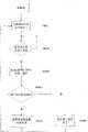
图1是本发明测试系统与CAN总线汽车仪表的连接示意图;Fig. 1 is the connection schematic diagram of test system of the present invention and CAN bus automobile instrument;
图2是本发明测试系统单片机的一种实施例的结构框图;Fig. 2 is the structural block diagram of a kind of embodiment of testing system single-chip microcomputer of the present invention;
图3是本发明测试系统一种单片机的结构图;Fig. 3 is the structural diagram of a kind of single-chip microcomputer of testing system of the present invention;
图4是本发明测试系统一种实施例的测试流程图;Fig. 4 is the testing flowchart of a kind of embodiment of testing system of the present invention;
图5是本发明测试系统另一种实施例的测试流程图。Fig. 5 is a test flowchart of another embodiment of the test system of the present invention.
具体实施方式Detailed ways
下面详细描述本发明的实施例,所述实施例的示例在附图中示出,其中自始至终相同或类似的标号表示相同或类似的元件或具有相同或类似功能的元件。下面通过参考附图描述的实施例是示例性的,仅用于解释本发明,而不能解释为对本发明的限制。Embodiments of the present invention are described in detail below, examples of which are shown in the drawings, wherein the same or similar reference numerals designate the same or similar elements or elements having the same or similar functions throughout. The embodiments described below by referring to the figures are exemplary only for explaining the present invention and should not be construed as limiting the present invention.
结合图1和图2所示,本发明CAN总线汽车仪表的测试系统包括单片机和CAN收发器,该单片机包括控制模块、存储模块、发送模块及计时模块,存储模块、发送模块、计时模块分别与所述控制模块电连接,发送模块通过CAN收发器与CAN总线汽车仪表相连接;In conjunction with Fig. 1 and shown in Fig. 2, the test system of CAN bus instrument of the present invention comprises single-chip microcomputer and CAN transceiver, and this single-chip microcomputer comprises control module, storage module, sending module and timing module, and storage module, sending module, timing module are connected with respectively The control module is electrically connected, and the sending module is connected with the CAN bus vehicle instrument through a CAN transceiver;
存储模块,用于存储CAN总线汽车仪表测试用的各种速度报文信息;The storage module is used to store various speed message information for CAN bus automotive instrument testing;
发送模块,用于向CAN总线汽车仪表发送各种速度报文;The sending module is used to send various speed messages to the CAN bus car instrument;
计时模块,用于在CAN总线汽车仪表测试中计时和计数;Timing module, used for timing and counting in CAN bus car meter test;
控制模块,用于控制所述存储模块、发送模块及计时模块工作。The control module is used to control the operation of the storage module, the sending module and the timing module.
测试系统与CAN总线汽车仪表通过CAN总线进行通讯,具体地,测试系统的发送模块通过通道RX和TX与CAN收发器相连接,CAN收发器通过CAN_H和CAN_L连接CAN总线汽车仪表,测试系统通过控制模块控制模拟产生CAN总线汽车仪表需要接收和处理的各种车速报文信息,并按一定的周期将该通信报文通过CAN线路(CAN_H和CAN_L)发送给CAN总线汽车仪表。The test system communicates with the CAN bus instrumentation through the CAN bus. Specifically, the transmission module of the test system is connected to the CAN transceiver through channels RX and TX. The CAN transceiver is connected to the CAN bus instrumentation through CAN_H and CAN_L. The test system is controlled by The module controls the simulation to generate various vehicle speed message information that the CAN bus car instrument needs to receive and process, and sends the communication message to the CAN bus car instrument through the CAN line (CAN_H and CAN_L) at a certain period.
存储模块,预先存储CAN总线汽车仪表测试用的各种车速报文信息,建立一个CAN总线汽车仪表报文数据库,包括各种车速报文,即从最小车速到最大车速之间的所有连续值速度报文。The storage module pre-stores various vehicle speed message information for CAN bus instrument testing, and establishes a CAN bus vehicle instrument message database, including various vehicle speed messages, that is, all continuous value speeds from the minimum vehicle speed to the maximum vehicle speed message.
发送模块,依照控制模块的控制向CAN总线汽车仪表发送各种车速报文;如控制模块需要控制测试系统发送一个15km/h的速度报文信息,首先控制模块会通过存储模块调取一个15km/h的报文信息,然后控制模块控制发送模块发送此报文信息到CAN总线汽车仪表,这样CAN总线汽车仪表就会显示一个15km/h的速度信息。The sending module, according to the control of the control module, sends various vehicle speed messages to the CAN bus instrument; if the control module needs to control the test system to send a speed message of 15km/h, first the control module will call a 15km/h speed message through the storage module. h message information, and then the control module controls the sending module to send this message information to the CAN bus vehicle instrument, so that the CAN bus vehicle instrument will display a speed information of 15km/h.
计时模块,在CAN总线汽车仪表的测试过程中,需要通过计时模块来进行相应的计时和计数,如报文发送周期计时、报文发送次数的计数和计时及一些数据变量的计数等,其具体的计时原理和计数过程将在下面具体的测试过程中一一详述。Timing module, in the test process of the CAN bus car instrument, it is necessary to carry out corresponding timing and counting through the timing module, such as the timing of the message sending cycle, the counting and timing of the number of message sending times, and the counting of some data variables, etc., the specific The timing principle and counting process will be detailed in the following specific test process.
控制模块,根据需求或者输出控制来控制存储模块、发送模块、计时模块进行相应的工作。控制模块可以根据需求调出存储模块内预存的相关速度报文信息,调出相关速度报文信息后,控制模块可以控制发送模块进行对此速度报文信息的模拟发送,控制发送模块将此报文信息模拟发送给CAN总线汽车仪表,而且,控制模块可以控制计时模块对相应速度报文的发送周期及报文次数进行计时或者计数,控制完成对CAN总线汽车仪表的各种的测试功能。The control module controls the storage module, the sending module, and the timing module to perform corresponding work according to demand or output control. The control module can call out the relevant speed message information pre-stored in the storage module according to the demand. After calling out the relevant speed message information, the control module can control the sending module to simulate the sending of the speed message information, and control the sending module to report the speed message information. The text information is simulated and sent to the CAN bus car instrument, and the control module can control the timing module to time or count the sending cycle and the number of messages of the corresponding speed message, and control the completion of various test functions for the CAN bus car instrument.
以上所述的单片机可以采用现有普通的带有计时模块的单片机对该CAN总线汽车仪表进行检测,只要对该单片机的内部控制程序按照本发明的控制策略进行重新编程即可。图3所示为本发明中优选采用的一种单片机,其型号为freescale的MC9S08DZ60单片机,该单片机的控制模块包括CPU,存储模块包括用户闪存、用户EEPROM、用户RAM,计时模块包括实时计数器、定时器,发送模块包括转换器、比较器及相应的输入输出端口,因该单片机为本领域的公知技术,因此其中每个模块的具体结构在此不做详述。该单片机通过发送模块的RX和TX接口与CAN收发器相连接,然后通过CAN收发器的CAN_H和CAN_L接口接入CAN总线汽车仪表。The above-mentioned single-chip microcomputer can adopt the existing common single-chip microcomputer with timing module to detect this CAN bus automobile instrument, as long as the internal control program of the single-chip microcomputer is reprogrammed according to the control strategy of the present invention. Fig. 3 is shown as a kind of single-chip microcomputer preferably adopted in the present invention, and its model is the MC9S08DZ60 single-chip microcomputer of freescale, and the control module of this single-chip microcomputer comprises CPU, and storage module comprises user's flash memory, user's EEPROM, user's RAM, and timing module comprises real-time counter, timing The sending module includes a converter, a comparator and corresponding input and output ports. Because the single-chip microcomputer is a well-known technology in the art, the specific structure of each module will not be described in detail here. The microcontroller is connected to the CAN transceiver through the RX and TX interfaces of the sending module, and then connected to the CAN bus vehicle instrument through the CAN_H and CAN_L interfaces of the CAN transceiver.
作为进一步改进,所述单片机通过I/O接口还连接一复位键,当系统需要初始化或者四种测试模式相互转换后并进行下一个模式的测试前,都可通过操作此复位键来对测试系统的控制程序进行初始化。优选地,测试系统的单片机通过I/O接口还连接有一显示装置,用来显示测试系统的工作情况;测试系统的单片机的普通I/O口还连接出两个按钮KEY1和KEY2。As a further improvement, the single-chip microcomputer is also connected to a reset key through the I/O interface. When the system needs to be initialized or the four test modes are converted to each other and before the test of the next mode is performed, the reset key can be operated to reset the test system. The control program is initialized. Preferably, the single-chip microcomputer of the test system is also connected to a display device through the I/O interface to display the working conditions of the test system; the common I/O port of the single-chip microcomputer of the test system is also connected with two buttons KEY1 and KEY2.
下面讲述测试系统对CAN总线汽车仪表进行测试的控制过程。在对CAN总线汽车仪表的丢包测试中,与测试系统中单片机连接的按钮KEY1用于增加测试系统的CAN负载率,即缩短测试系统内部的车速报文发送周期,与测试系统中单片机连接的按钮KEY2用于降低测试系统的CAN负载率,在丢包测试模式中,通过按钮KEY1可以增加报文发送时不能正确发送数据报文的概率,通过按钮KEY2可以减小报文发送时不能正确发送数据报文的概率,例如,测试系统内部设定报文不能正确发送的概率为15%,也就是说,每发送100次速度报文的时候,系统应该模拟有15次的速度报文数据发送是不正确的,那么通过操作按钮KEY1可以增加报文发送时不能正确发送数据报文的概率,如增大到20%,只要变化为比15%大的一个概率就可以;而通过按钮KEY2可以减小报文发送时不能正确发送数据报文的概率,如减小到10%,只要变化为比15%小的一个概率就可以。The following describes the control process for the test system to test the CAN bus vehicle instrument. In the packet loss test of the CAN bus car instrument, the button KEY1 connected with the single-chip microcomputer in the test system is used to increase the CAN load rate of the test system, that is, to shorten the sending cycle of the vehicle speed message inside the test system, and the button KEY1 connected with the single-chip microcomputer in the test system The button KEY2 is used to reduce the CAN load rate of the test system. In the packet loss test mode, the probability of incorrectly sending data packets can be increased by pressing the button KEY1, and the probability of incorrectly sending data packets can be reduced by pressing the button KEY2. The probability of the data message, for example, the test system internally sets the probability that the message cannot be sent correctly as 15%, that is to say, for every 100 speed messages sent, the system should simulate 15 speed message data transmissions If it is incorrect, then the probability that the data message cannot be sent correctly can be increased by operating the button KEY1, such as increasing to 20%, as long as it is changed to a probability greater than 15%. To reduce the probability that the data message cannot be sent correctly when the message is sent, for example, to 10%, it only needs to be changed to a probability smaller than 15%.
同时,在系统内部设定一个变量数据random,random的取值可取1--100内的任意一个数值,即测试过程中测试系统可以将1--100以内的任何一个数值以均等的机会分配给数据变量random,也就是数据变量random被赋予1--100内的任意一个数值的概率都是相等的,都为1%,然后系统内部设定两个变量值data1和data2,两个变量的关系为,1≤data1≤data2≤100,然后测试系统可以开始对CAN总线汽车仪表进行丢包测试模式的测试。At the same time, set a variable data random in the system, the value of random can take any value within 1-100, that is, the test system can assign any value within 1-100 to the The data variable random, that is, the probability that the data variable random is assigned any value within 1--100 is equal, both are 1%, and then the system internally sets two variable values data1 and data2, and the relationship between the two variables For, 1≤data1≤data2≤100, then the test system can start to perform the packet loss test mode test on the CAN bus automotive instrument.
实施例一Embodiment one
如图4所示,测试系统先进行初始化;As shown in Figure 4, the test system is initialized first;
步骤S0001,控制模块控制计时模块清零并开始计时;Step S0001, the control module controls the timing module to reset and start timing;
步骤S0002,控制模块判断计时模块的计时时间是否达到其系统内部设定的车速报文发送周期T_SPD;如果判断结果为是,系统进入步骤S0003,如果判断结果为否,则控制模块控制计时模块继续进行计时;Step S0002, the control module judges whether the timing time of the timing module has reached the vehicle speed message sending period T_SPD set in the system; if the judgment result is yes, the system enters step S0003, if the judgment result is no, the control module controls the timing module to continue timekeeping;
步骤S0003,控制模块控制随机变量random从数值1--100内随意取一数值,然后系统进入步骤S0004;Step S0003, the control module controls the random variable random to randomly take a value from the value 1--100, and then the system enters step S0004;
步骤S0004,控制模块比较随机变量random的数值与其内部设定的数据变量data1和data2的大小;如果满足data1≤random≤data2,则系统进入步骤S0005,如果不满足关系式data1≤random≤data2,则系统进入步骤S006。Step S0004, the control module compares the value of the random variable random with the size of the internally set data variables data1 and data2; if data1≤random≤data2 is satisfied, the system enters step S0005; if the relationship data1≤random≤data2 is not satisfied, then The system enters step S006.
步骤S0005,控制模块控制发送模块放弃当前速度报文的发送,即形成丢包;然后系统返回步骤S0001继续进行下一个循环;Step S0005, the control module controls the sending module to give up the sending of the current speed message, that is, packet loss is formed; then the system returns to step S0001 to continue the next cycle;
步骤S0006,即random不满足关系式data1≤random≤data2,此时控制模块控制发送模块发送当前速度报文,之后系统返回步骤S0001进行下一个速度报文发送循环;Step S0006, that is, random does not satisfy the relation data1≤random≤data2, at this time the control module controls the sending module to send the current speed message, and then the system returns to step S0001 for the next speed message sending cycle;
在以上测试流程中,测试系统内部报文丢包的概率为(data2-data1+1)/100,如果需要增大测试系统的丢包的概率,则可以通过控制按钮KEY1的操作来实现,通过控制按钮KEY1的操作可以实现改变测试系统内部变量data1和data2的数值,即通过增大变量data2的取值或者减小变量data1的取值来实现增大测试系统内部的丢包概率。但是变量data1和data2的数值在满足关系式data1≤data2的同时不能超出1--100的数值范围;同样通过控制按钮KEY2的操作可以实现改变测试系统内部变量data1和data2的数值,即通过减小变量data2的取值或者增大变量data1的取值来实现减小测试系统内部的丢包概率。但是变量data1和data2的数值同样在满足关系式data1≤data2的同时不能超出1--100的数值范围;通过以上方式,可以在通过按钮KEY1或按钮KEY2改变测试系统内部设定的丢包概率后再对CAN总线汽车仪表进行重复检测。In the above test process, the probability of packet loss inside the test system is (data2-data1+1)/100. If you need to increase the probability of packet loss in the test system, you can achieve it by operating the control button KEY1. The operation of the control button KEY1 can change the values of the internal variables data1 and data2 of the test system, that is, increase the value of the variable data2 or decrease the value of the variable data1 to increase the probability of packet loss inside the test system. However, the values of the variables data1 and data2 cannot exceed the value range of 1--100 while satisfying the relationship data1≤data2; also by operating the control button KEY2, the values of the internal variables data1 and data2 of the test system can be changed, that is, by reducing Change the value of the variable data2 or increase the value of the variable data1 to reduce the probability of packet loss inside the test system. However, the values of the variables data1 and data2 must also satisfy the relationship data1≤data2 and cannot exceed the value range of 1--100; through the above method, you can change the packet loss probability set inside the test system through the button KEY1 or button KEY2 Then repeat the detection of the CAN bus car instrument.
实施例二Embodiment two
如图5所示,测试系统先进行初始化;As shown in Figure 5, the test system is initialized first;
步骤S0001,控制模块控制计时模块清零并开始计时;Step S0001, the control module controls the timing module to reset and start timing;
步骤S0002,控制模块判断计时模块的计时时间是否达到其系统内部设定的车速报文发送周期T_SPD;如果判断结果为是,系统进入步骤S0003,如果判断结果为否,则控制模块控制计时模块继续进行计时;Step S0002, the control module judges whether the timing time of the timing module has reached the vehicle speed message sending period T_SPD set in the system; if the judgment result is yes, the system enters step S0003, if the judgment result is no, the control module controls the timing module to continue timekeeping;
步骤S0003,控制模块控制随机变量random从数值1--100内随意取一数值,然后系统进入步骤S0004;Step S0003, the control module controls the random variable random to randomly take a value from the value 1--100, and then the system enters step S0004;
步骤S0004,控制模块比较随机变量random的数值与其内部设定的数据变量data1和data2的大小;如果满足data1≤random≤data2,则系统进入步骤S0005,如果不满足关系式data1≤random≤data2,则系统进入步骤S006。Step S0004, the control module compares the value of the random variable random with the size of the internally set data variables data1 and data2; if data1≤random≤data2 is satisfied, the system enters step S0005; if the relationship data1≤random≤data2 is not satisfied, then The system enters step S006.
步骤S0005,控制模块调取并修改当前速度报文,将修改后一个错误速度报文发送给CAN总线汽车仪表;然后系统返回步骤S0001继续进行下一个循环;Step S0005, the control module retrieves and modifies the current speed message, and sends a modified wrong speed message to the CAN bus vehicle instrument; then the system returns to step S0001 to continue the next cycle;
步骤S0006,即random不满足关系式data1≤random≤data2,此时控制模块控制发送模块发送当前速度报文,之后系统返回步骤S0001进行下一个速度报文发送循环;Step S0006, that is, random does not satisfy the relation data1≤random≤data2, at this time the control module controls the sending module to send the current speed message, and then the system returns to step S0001 for the next speed message sending cycle;
这样通过按钮KEY1或按钮KEY2也可以改变测试系统内部设定的发送错误报文数据的概率,然后再对CAN总线汽车仪表进行重复检测。In this way, the probability of sending error message data set inside the test system can also be changed through the button KEY1 or button KEY2, and then the CAN bus car instrument is repeatedly tested.
以上两个实施例中,考虑到测试的便捷性,变量data1优选取值为1,变量data2优选取值为15。In the above two embodiments, considering the convenience of testing, the variable data1 preferably takes a value of 1, and the variable data2 preferably takes a value of 15.
在以上测试过程中,对CAN总线汽车仪表进行丢包测试的目的是为了观察仪表在恶劣的CAN通信状况下的工作状况,通过测试观察仪表指示、显示部分的工作状况间接的反应出整车的CAN通信状况,如果在检测过程中发现汽车仪表的显示与测试系统显示装置显示的工作状况不一致,则表明CAN总线汽车仪表存在问题需要进一步优化,进一步讲,当测试系统发生丢包或者发送错误报文数据时,CAN总线汽车仪表的指示与测试系统显示的不一致,则CAN总线汽车仪表工作存在问题需要进一步优化,通过这种检测可以为CAN总线汽车仪表装车时可能出现的问题做提前测试、分析、改进。In the above test process, the purpose of the packet loss test on the CAN bus vehicle instrument is to observe the working condition of the instrument under the harsh CAN communication condition, and to observe the working condition of the indicator and display part of the instrument through the test to indirectly reflect the status of the whole vehicle. CAN communication status, if it is found that the display of the vehicle instrument is inconsistent with the working status displayed by the test system display device during the detection process, it indicates that there is a problem with the CAN bus vehicle instrument and needs to be further optimized. Further speaking, when the test system loses packets or sends an error report When reading data, if the indication of the CAN bus car instrument is inconsistent with the display of the test system, there are problems in the work of the CAN bus car instrument that need to be further optimized. Through this detection, it is possible to do early testing for the possible problems that may occur when the CAN bus car instrument is loaded. Analyze, improve.
本测试方法是对汽车组合仪表失效模式的一种测试,通过测试、观察CAN总线汽车仪表在恶劣的汽车CAN总线通信状况下的工作情况,为CAN总线汽车仪表装车时可能出现的问题做分析、参考,做到提前发现、暴露问题,及时解决问题。缩短了CAN总线汽车组合仪表的测试周期,降低了CAN总线汽车仪表的测试成本。This test method is a test for the failure mode of the automobile combination meter. By testing and observing the working conditions of the CAN bus car meter under the harsh automotive CAN bus communication conditions, it analyzes the possible problems when the CAN bus car meter is loaded. , reference, so as to discover and expose problems in advance and solve them in time. The test cycle of the CAN bus vehicle combination instrument is shortened, and the test cost of the CAN bus vehicle instrument is reduced.
以上所述仅为本发明的较佳实施例而已,并不用以限制本发明,凡在本发明的精神和原则之内所作的任何修改、等同替换和改进等,均应包含在本发明的保护范围之内。The above descriptions are only preferred embodiments of the present invention, and are not intended to limit the present invention. Any modifications, equivalent replacements and improvements made within the spirit and principles of the present invention should be included in the protection of the present invention. within range.
Claims (11)
Priority Applications (1)
| Application Number | Priority Date | Filing Date | Title |
|---|---|---|---|
| CN 200910190557CN102033541B (en) | 2009-09-30 | 2009-09-30 | System for testing automobile instrument with controller area network (CAN) bus and testing method thereof |
Applications Claiming Priority (1)
| Application Number | Priority Date | Filing Date | Title |
|---|---|---|---|
| CN 200910190557CN102033541B (en) | 2009-09-30 | 2009-09-30 | System for testing automobile instrument with controller area network (CAN) bus and testing method thereof |
Publications (2)
| Publication Number | Publication Date |
|---|---|
| CN102033541Atrue CN102033541A (en) | 2011-04-27 |
| CN102033541B CN102033541B (en) | 2013-03-13 |
Family
ID=43886553
Family Applications (1)
| Application Number | Title | Priority Date | Filing Date |
|---|---|---|---|
| CN 200910190557ActiveCN102033541B (en) | 2009-09-30 | 2009-09-30 | System for testing automobile instrument with controller area network (CAN) bus and testing method thereof |
Country Status (1)
| Country | Link |
|---|---|
| CN (1) | CN102033541B (en) |
Cited By (6)
| Publication number | Priority date | Publication date | Assignee | Title |
|---|---|---|---|---|
| CN102032927A (en)* | 2009-09-30 | 2011-04-27 | 比亚迪股份有限公司 | System for testing sensitivity of automobile instrument with controller area network (CAN) bus and testing method thereof |
| CN102033141B (en)* | 2009-09-30 | 2013-01-02 | 比亚迪股份有限公司 | Test system based on CAN (Controller Area Network) bus automobile instrument and method |
| CN106094791A (en)* | 2016-06-14 | 2016-11-09 | 北京汽车股份有限公司 | Vehicle Controller and acquisition methods fault time, diagnostic system and automobile |
| CN106200609A (en)* | 2015-04-29 | 2016-12-07 | 陕西中交天健车联网信息技术有限公司 | Automatically the device and method of engine of heavy-duty car ECU software version is tested |
| CN108023797A (en)* | 2016-10-28 | 2018-05-11 | Lnb科技株式会社 | The public broadcasting device to be communicated using controller local area network |
| CN115643124A (en)* | 2022-06-23 | 2023-01-24 | 南京轶诺科技有限公司 | PC simulation automobile CAN bus communication system |
Family Cites Families (2)
| Publication number | Priority date | Publication date | Assignee | Title |
|---|---|---|---|---|
| CN1304909C (en)* | 2005-11-03 | 2007-03-14 | 重庆邮电学院 | Monitoring instrument of vehicle control system CAN/LIN network and its test method |
| CN200956107Y (en)* | 2006-08-18 | 2007-10-03 | 浙江大学 | Vehicle-mounted online performance test device based on CAN bus |
- 2009
- 2009-09-30CNCN 200910190557patent/CN102033541B/enactiveActive
Cited By (8)
| Publication number | Priority date | Publication date | Assignee | Title |
|---|---|---|---|---|
| CN102032927A (en)* | 2009-09-30 | 2011-04-27 | 比亚迪股份有限公司 | System for testing sensitivity of automobile instrument with controller area network (CAN) bus and testing method thereof |
| CN102033141B (en)* | 2009-09-30 | 2013-01-02 | 比亚迪股份有限公司 | Test system based on CAN (Controller Area Network) bus automobile instrument and method |
| CN102032927B (en)* | 2009-09-30 | 2013-09-18 | 比亚迪股份有限公司 | System for testing sensitivity of automobile instrument with controller area network (CAN) bus and testing method thereof |
| CN106200609A (en)* | 2015-04-29 | 2016-12-07 | 陕西中交天健车联网信息技术有限公司 | Automatically the device and method of engine of heavy-duty car ECU software version is tested |
| CN106094791A (en)* | 2016-06-14 | 2016-11-09 | 北京汽车股份有限公司 | Vehicle Controller and acquisition methods fault time, diagnostic system and automobile |
| CN106094791B (en)* | 2016-06-14 | 2019-01-08 | 北京汽车股份有限公司 | Vehicle Controller and its fault time acquisition methods, diagnostic system and automobile |
| CN108023797A (en)* | 2016-10-28 | 2018-05-11 | Lnb科技株式会社 | The public broadcasting device to be communicated using controller local area network |
| CN115643124A (en)* | 2022-06-23 | 2023-01-24 | 南京轶诺科技有限公司 | PC simulation automobile CAN bus communication system |
Also Published As
| Publication number | Publication date |
|---|---|
| CN102033541B (en) | 2013-03-13 |
Similar Documents
| Publication | Publication Date | Title |
|---|---|---|
| CN102033141B (en) | Test system based on CAN (Controller Area Network) bus automobile instrument and method | |
| CN102032927B (en) | System for testing sensitivity of automobile instrument with controller area network (CAN) bus and testing method thereof | |
| CN102033540B (en) | System for testing automobile instrument with a controller area network (CAN) bus and testing method thereof | |
| CN107145140B (en) | Automatic test system and test method for CAN interface of vehicle-mounted electronic control unit | |
| CN102033541A (en) | System for testing automobile instrument with controller area network (CAN) bus and testing method thereof | |
| US7810004B2 (en) | Integrated circuit having a subordinate test interface | |
| CN110609491B (en) | Accident identification method and system for semi-physical simulation of electric vehicle controller | |
| CN102566567B (en) | Electronic control unit (ECU) sensor signal fault injection device for engine hardware in-the-loop simulation (HILS) system | |
| CN207440601U (en) | A kind of CAN bus message dropping test system of automobile instrument | |
| WO2024050959A1 (en) | Mobile battery state detection device, system, and method | |
| CN106656663A (en) | Bit flip fault injection method and system for CAN (Controller Area Network) bus data link layer | |
| CN109901555A (en) | A kind of car fault diagnosis method, equipment and storage medium | |
| CN108803577A (en) | A kind of diagnostic method, host computer and slave computer | |
| CN104568459A (en) | OBD intelligent device, test method and system thereof, and ECU simulator | |
| CN108490921B (en) | A kind of engine testing system | |
| CN102915033A (en) | Vehicle fault diagnosing system and engineering machine | |
| CN114967657A (en) | Position sensor simulation method and EGSM hardware-in-loop test system | |
| CN115190030A (en) | Hardware device and UVM verification platform for realizing CAN FD | |
| JPH08163151A (en) | Serial communication device | |
| CN108444517B (en) | Portable multi-function instrument test load test box and instrument detection method | |
| CN201725219U (en) | Automobile type configuration detecting device based on bus communication | |
| CN201659856U (en) | Automobile tire detection device based on CAN bus | |
| WO2016145405A1 (en) | Intelligent packet analyzer circuits, systems, and methods | |
| CN112269365A (en) | Rapid detection method for vehicle-mounted terminal hardware circuit | |
| CN102075370A (en) | Calibration and verification system of engine control model (ECM) communication based on virtual network and virtual node |
Legal Events
| Date | Code | Title | Description |
|---|---|---|---|
| C06 | Publication | ||
| PB01 | Publication | ||
| C10 | Entry into substantive examination | ||
| SE01 | Entry into force of request for substantive examination | ||
| C14 | Grant of patent or utility model | ||
| GR01 | Patent grant | ||
| TR01 | Transfer of patent right | ||
| TR01 | Transfer of patent right | Effective date of registration:20201124 Address after:215500 No.13, Caotang Road, Changshu, Suzhou, Jiangsu Province Patentee after:Changshu intellectual property operation center Co.,Ltd. Address before:Room 3a12, building A1, 1983 creative Town, No.29 Nanxin street, Nanling village community, Nanwan street, Longgang District, Shenzhen City, Guangdong Province Patentee before:Shenzhen Chengze Information Technology Co.,Ltd. Effective date of registration:20201124 Address after:Room 3a12, building A1, 1983 creative Town, No.29 Nanxin street, Nanling village community, Nanwan street, Longgang District, Shenzhen City, Guangdong Province Patentee after:Shenzhen Chengze Information Technology Co.,Ltd. Address before:518118 Pingshan Road, Pingshan Town, Shenzhen, Guangdong, No. 3001, No. Patentee before:BYD Co.,Ltd. | |
| CP02 | Change in the address of a patent holder | ||
| CP02 | Change in the address of a patent holder | Address after:215500 5th floor, building 4, 68 Lianfeng Road, Changfu street, Changshu City, Suzhou City, Jiangsu Province Patentee after:Changshu intellectual property operation center Co.,Ltd. Address before:No.13 caodang Road, Changshu City, Suzhou City, Jiangsu Province Patentee before:Changshu intellectual property operation center Co.,Ltd. |