CN102032871A - Characteristic line-based optical measurement method for position and attitude of moving object - Google Patents
Characteristic line-based optical measurement method for position and attitude of moving objectDownload PDFInfo
- Publication number
- CN102032871A CN102032871ACN 201010563504CN201010563504ACN102032871ACN 102032871 ACN102032871 ACN 102032871ACN 201010563504CN201010563504CN 201010563504CN 201010563504 ACN201010563504 ACN 201010563504ACN 102032871 ACN102032871 ACN 102032871A
- Authority
- CN
- China
- Prior art keywords
- formula
- coordinate system
- measurement
- target
- attitude
- Prior art date
- Legal status (The legal status is an assumption and is not a legal conclusion. Google has not performed a legal analysis and makes no representation as to the accuracy of the status listed.)
- Pending
Links
- 230000003287optical effectEffects0.000titleabstractdescription9
- 238000000691measurement methodMethods0.000titleabstractdescription8
- 238000005259measurementMethods0.000claimsabstractdescription63
- 238000000034methodMethods0.000claimsabstractdescription20
- 239000011159matrix materialSubstances0.000claimsdescription27
- 239000013598vectorSubstances0.000claimsdescription21
- 238000013519translationMethods0.000claimsdescription3
- 238000010606normalizationMethods0.000claims2
- 238000006467substitution reactionMethods0.000claims2
- 239000002131composite materialSubstances0.000claims1
- 238000005516engineering processMethods0.000abstractdescription3
- 238000012544monitoring processMethods0.000abstractdescription3
- 238000004088simulationMethods0.000abstractdescription2
- 230000007547defectEffects0.000abstract1
- 238000010276constructionMethods0.000description2
- 238000007405data analysisMethods0.000description2
- 238000000605extractionMethods0.000description2
- 238000012795verificationMethods0.000description2
- 230000009286beneficial effectEffects0.000description1
- 238000010586diagramMethods0.000description1
- 239000000203mixtureSubstances0.000description1
- 238000012545processingMethods0.000description1
- 230000000007visual effectEffects0.000description1
Images


Landscapes
- Length Measuring Devices By Optical Means (AREA)
Abstract
Description
Translated fromChinese技术领域technical field
本发明涉及视觉测量中的一种运动目标位姿测量技术,具体涉及一种基于特征线的位姿光学测量方法。The invention relates to a moving object pose measurement technology in visual measurement, in particular to a feature line-based pose optical measurement method.
背景技术Background technique
传统的监测系统一般采用在运动目标上直接安装特征点,通过对特征点进行拍摄,处理其图像信息获得飞行器运动参数的方法,此种方法特征点的布局直接影响测量精度,具体而言,特征点间的测量基线越长,相同特征点定位误差条件下测量精度越高;反之测量精度低。按照现有的方法和技术,为了提高测量精度必须增加特征点间的距离,但特征点间的距离受限于运动目标的尺寸,同时特征点距离的增加导致配合目标重量的增加。而已有的传统方法每个特征点至少需要两台摄像机。当采用目标上特征点对目标运动参数进行测量时,其测量精度不仅与特征点在两个坐标系中的坐标测量精度有关,而且受特征点间的相对位置的影响。The traditional monitoring system generally adopts the method of directly installing feature points on the moving target, and obtaining the motion parameters of the aircraft by shooting the feature points and processing the image information. The layout of the feature points in this method directly affects the measurement accuracy. Specifically, the feature points The longer the measurement baseline between points, the higher the measurement accuracy under the same feature point positioning error; otherwise, the measurement accuracy is low. According to the existing methods and technologies, in order to improve the measurement accuracy, the distance between the feature points must be increased, but the distance between the feature points is limited by the size of the moving target, and the increase in the distance between the feature points leads to an increase in the weight of the matching target. However, the existing traditional methods require at least two cameras for each feature point. When the feature points on the target are used to measure the motion parameters of the target, the measurement accuracy is not only related to the coordinate measurement accuracy of the feature points in the two coordinate systems, but also affected by the relative position of the feature points.
发明内容Contents of the invention
本发明为了解决传统的监测系统测量精度低和稳定性差,以及对于特征点装配位置要求高的缺点,而提出了一种基于特征线的运动目标位姿光学测量方法。In order to solve the shortcomings of the traditional monitoring system, such as low measurement accuracy and poor stability, and high requirements for assembly positions of feature points, the present invention proposes an optical measurement method for the position and posture of a moving target based on feature lines.
本发明的一种基于特征线的运动目标位姿光学测量方法的测量过程如下:The measurement process of a kind of characteristic line-based optical measurement method of moving target pose of the present invention is as follows:
在运动目标上安装特征点,首次设运动目标上存在不平行的两条直线L1和L2,P1、P2、P3和P4分别为直线上的点,其中点P1和P3位于直线L1上,点P2和P4位于直线L2上,所述的P1、P2、P3和P4四个点为特征点,定义所述四个特征点在目标坐标系和测量坐标系中的坐标分别为Pmi,Pgi,其中i=1,2,3,4;Install feature points on the moving target. For the first time,itis assumed that there are two non-parallel straight linesL1 and L2 onthe moving target.3 is located on the straight line L1 , points P2 and P4 are located on the straight line L2 , the four points P1 , P2 , P3 and P4 are feature points, and the four feature points are defined in the target coordinates The coordinates in the coordinate system and the measurement coordinate system are respectively Pmi , Pgi , where i=1, 2, 3, 4;
目标坐标系与运动目标固连,其原点Om取在运动目标的质心上,则Pmi的值为定值;The target coordinate system is fixedly connected with the moving target, and its origin Om is taken on the center of mass of the moving target, then the value of Pmi is a fixed value;
测量坐标系随运动目标的运动而变化,测量坐标系是确定运动目标的质心在空间的坐标位置及其在空间的姿态的参考基准,其中空间的坐标位置是三个方向的平动:X方向位置、Y方向位置和Z方向位置,空间的姿态是绕三个方向轴的转动:俯仰角、偏航角和滚转角,则Pgi的值是测量值,是未知值;The measurement coordinate system changes with the movement of the moving target. The measurement coordinate system is a reference to determine the coordinate position of the center of mass of the moving target in space and its attitude in space. The coordinate position in space is the translation in three directions: X direction Position, position in the Y direction and position in the Z direction, the attitude of the space is the rotation around the three direction axes: pitch angle, yaw angle and roll angle, then the value of Pgi is a measured value and an unknown value;
在任意时刻,同一特征点在目标坐标系和测量坐标系中的坐标均满足如下关系:At any moment, the coordinates of the same feature point in the target coordinate system and the measurement coordinate system satisfy the following relationship:
Pgi=CgmPmi+Tmgo i=1,2,3,4 公式一Pgi =Cgm Pmi +Tmgo i=1, 2, 3, 4
式中Cgm——目标坐标系相对于测量坐标系的旋转矩阵Cmg的逆;where Cgm is the inverse of the rotation matrix Cmg of the target coordinate system relative to the measurement coordinate system;
Tmgo——目标坐标系原点在测量坐标系中的位置向量;Tmgo ——the position vector of the origin of the target coordinate system in the measurement coordinate system;
把公式一中i=1和i=3时的等式两边分别作差,再把公式一中i=2和i=4时的等式两边也分别作差,可得:Make the difference on both sides of the equation when i=1 and i=3 in the formula one, and then make the difference on both sides of the equation when i=2 and i=4 in the formula one, and you can get:
Pg(j+2)-Pgj=Cgm(Pm(j+2)-Pmj) j=1,2 公式二Pg(j+2) -Pgj =Cgm (Pm(j+2) -Pmj ) j=1,2 Formula 2
对其两端向量进行归一化,如下式所示:Normalize the vectors at both ends, as shown in the following formula:
公式三formula three
又因为旋转矩阵Cgm为正交阵,所以公式三可进一步表示为:And because the rotation matrix Cgm is an orthogonal matrix,
公式四formula four
定义definition
公式五formula five
则,公式四更简洁、直观地表示为:Then,
Agj=CgmAmj j=1,2 公式六Agj =Cgm Amj j=1,2 Formula 6
因为旋转矩阵Cgm是正交阵,所以对于向量Ag1和Ag2,如下关系也成立:Because the rotation matrix Cgm is an orthogonal matrix, the following relations also hold for vectors Ag1 and Ag2 :
Ag1×Ag2=(CgmAm1)×(CgmAm2)=Cgm(Am1×Am2) 公式七Ag1 ×Ag2 =(Cgm Am1 )×(Cgm Am2 )=Cgm (Am1 ×Am2 ) Formula 7
依据四个特征点不共线的条件,可知公式七两边均为非零向量,对公式七两端进行归一化:According to the condition that the four feature points are not collinear, it can be seen that both sides of formula 7 are non-zero vectors, and the two sides of formula 7 are normalized:
同理定义Same definition
把Bg和Bm代入公式八,可得:Substituting Bg and Bm into formula 8, we can get:
Bg=CgmBm 公式十Bg = Cgm Bm formula ten
把公式六和公式十两端的向量组合成矩阵,并定义Combine the vectors at both ends of formula 6 and
则公式六和公式十可用一个矩阵等式表示为:Then formula 6 and
Dg=CgmDm 公式十一Dg =Cgm Dm Formula 11
由Dg和Dm的构造方法,以及四个特征点不重合且不共线的条件可知:Dg和Dm均满秩,因此,可以通过公式十二求取目标坐标系相对于测量坐标系的旋转矩阵Cmg:From the construction method of Dg and Dm , and the condition that the four feature points do not coincide and are not collinear, it can be seen that: Dg and Dm are both full rank, therefore, the target coordinate system relative to the measurement coordinate can be obtained by formula 12 The rotation matrix Cmg of the system:
分别求取P1和P3所在直线L1与P2和P4所在直线L2的交点或公垂线的中点在目标坐标系中的坐标Xm和在测量坐标系中的坐标Xg;把Cgm、Xm和Xg代入公式十三,就可以求得目标坐标系相对于测量坐标系的位置向量Tmgo,用显式可表示为:Respectively obtain the coordinate Xm in the target coordinate system and the coordinate Xg in the measurement coordinate system of the intersection point of the straight line L1 where P 1and P3 are located and the straight line L2 where P2 and P4 are located or the midpoint of the common vertical line; Substituting Cgm, Xm and Xg into formula 13, the position vector Tmgo of the target coordinate system relative to the measurement coordinate system can be obtained, which can be explicitly expressed as:
Tmgo=Xg-CgmXm 公式十三Tmgo =Xg -Cgm Xm Formula 13
将求得的旋转矩阵Cmg和位置向量Tmgo带入到公式一中,根据Pmi的值就能够得到Pgi的值,即得到测量结果。Bring the obtained rotation matrix Cmg and position vector Tmgo into
有益效果:本发明提出了一种基于特征线的运动目标相对位置姿态的光学测量方法,并对测量误差进行了分析。与其他测量方法相比,它具有如下特点:①无需量测特征光点在目标坐标系中坐标;②对摄像机模型没有限制;③位置姿态的测量值具有解析解。实际测量结果验证了该方法的可行性和有效性。Beneficial effects: the present invention proposes an optical measurement method for the relative position and attitude of the moving target based on the characteristic line, and analyzes the measurement error. Compared with other measurement methods, it has the following characteristics: ① There is no need to measure the coordinates of the characteristic light point in the target coordinate system; ② There is no restriction on the camera model; ③ The measured value of the position and attitude has an analytical solution. The actual measurement results verify the feasibility and effectiveness of the method.
附图说明Description of drawings
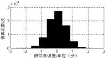
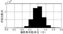
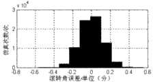
图1是本发明的原理图;图2至图7是使用本发明方法测得的运动目标相对位置姿态测量误差直方图仿真结果,图2是俯仰角误差,图3是偏航角误差,图4是滚转角误差,图5是X方向位置误差,图6是Y方向位置误差,图7是Z方向位置误差;图8和图9是使用本发明方法对目标零位位置姿态已知时Rx实测数据分析;图10和图11是使用本发明方法对目标零位位置姿态已知时Tx实测数据分析。Fig. 1 is a principle diagram of the present invention; Fig. 2 to Fig. 7 are the histogram simulation results of the relative position attitude measurement error of the moving target using the method of the present invention to measure, Fig. 2 is pitch angle error, Fig. 3 is yaw angle error, Fig. 4 is the roll angle error, Fig. 5 is the position error in the X direction, Fig. 6 is the position error in the Y direction, and Fig. 7 is the position error in the Z direction; Fig. 8 and Fig. 9 are Rx measured data analysis; Fig. 10 and Fig. 11 are the Tx measured data analysis when the target zero position attitude is known using the method of the present invention.
具体实施方式Detailed ways
具体实施方式一:结合图1说明本实施方式,本实施方式的测量过程如下:Specific embodiment one: illustrate this embodiment in conjunction with Fig. 1, the measurement process of this embodiment is as follows:
在运动目标上安装特征点,首次设运动目标上存在不平行的两条直线L1和L2,P1、P2、P3和P4分别为直线上的点,其中点P1和P3位于直线L1上,点P2和P4位于直线L2上,所述的P1、P2、P3和P4四个点为特征点,定义所述四个特征点在目标坐标系和测量坐标系中的坐标分别为Pmi,Pgi,其中i=1,2,3,4;Install feature points on the moving target. For the first time,itis assumed that there are two non-parallel straight linesL1 and L2 onthe moving target.3 is located on the straight line L1 , points P2 and P4 are located on the straight line L2 , the four points P1 , P2 , P3 and P4 are feature points, and the four feature points are defined in the target coordinates The coordinates in the coordinate system and the measurement coordinate system are respectively Pmi , Pgi , where i=1, 2, 3, 4;
目标坐标系与运动目标固连,其原点Om取在运动目标的质心上,则Pmi的值为定值;The target coordinate system is fixedly connected with the moving target, and its origin Om is taken on the center of mass of the moving target, then the value of Pmi is a fixed value;
测量坐标系随运动目标的运动而变化,测量坐标系是确定运动目标的质心在空间的坐标位置及其在空间的姿态的参考基准,其中空间的坐标位置是三个方向的平动:X方向位置、Y方向位置和Z方向位置,空间的姿态是绕三个方向轴的转动:俯仰角、偏航角和滚转角,则Pgi的值是测量值,是未知值;The measurement coordinate system changes with the movement of the moving target. The measurement coordinate system is a reference to determine the coordinate position of the center of mass of the moving target in space and its attitude in space. The coordinate position in space is the translation in three directions: X direction Position, position in the Y direction and position in the Z direction, the attitude of the space is the rotation around the three direction axes: pitch angle, yaw angle and roll angle, then the value of Pgi is a measured value and an unknown value;
在任意时刻,同一特征点在目标坐标系和测量坐标系中的坐标均满足如下关系:At any moment, the coordinates of the same feature point in the target coordinate system and the measurement coordinate system satisfy the following relationship:
Pgi=CgmPmi+Tmgo i=1,2,3,4 公式一Pgi =Cgm Pmi +Tmgo i=1, 2, 3, 4
式中Cgm——目标坐标系相对于测量坐标系的旋转矩阵Cmg的逆;where Cgm is the inverse of the rotation matrix Cmg of the target coordinate system relative to the measurement coordinate system;
Tmgo——目标坐标系原点在测量坐标系中的位置向量;Tmgo ——the position vector of the origin of the target coordinate system in the measurement coordinate system;
把公式一中i=1和i=3时的等式两边分别作差,再把公式一中i=2和i=4时的等式两边也分别作差,可得:Make the difference on both sides of the equation when i=1 and i=3 in the formula one, and then make the difference on both sides of the equation when i=2 and i=4 in the formula one, and you can get:
Pg(j+2)-Pgj=Cgm(Pm(j+2)-Pmj) j=1,2 公式二Pg(j+2) -Pgj =Cgm (Pm(j+2) -Pmj ) j=1,2 Formula 2
当特征点不重合时,公式二两边均不是零向量。此时,可对其两端向量进行归一化,如下式所示:When the feature points do not coincide, both sides of formula 2 are not zero vectors. At this point, the vectors at both ends can be normalized, as shown in the following formula:
公式三formula three
又因为旋转矩阵Cgm为正交阵,所以公式三可进一步表示为:And because the rotation matrix Cgm is an orthogonal matrix,
公式四formula four
定义definition
公式五formula five
则,公式四更简洁、直观地表示为:Then,
Agj=CgmAmj j=1,2 公式六Agj =Cgm Amj j=1,2 Formula 6
因为旋转矩阵Cgm是正交阵,所以对于向量Ag1和Ag2,如下关系也成立:Because the rotation matrix Cgm is an orthogonal matrix, the following relations also hold for vectors Ag1 and Ag2 :
Ag1×Ag2=(CgmAm1)×(CgmAm2)=Cgm(Am1×Am2) 公式七Ag1 ×Ag2 =(Cgm Am1 )×(Cgm Am2 )=Cgm (Am1 ×Am2 ) Formula 7
依据四个特征点不共线的条件,可知公式七两边均为非零向量,对公式七两端进行归一化:According to the condition that the four feature points are not collinear, it can be seen that both sides of formula 7 are non-zero vectors, and the two sides of formula 7 are normalized:
同理定义Same definition
把Bg和Bm代入公式八,可得:Substituting Bg and Bm into formula 8, we can get:
Bg=CgmBm 公式十Bg = Cgm Bm formula ten
把公式六和公式十两端的向量组合成矩阵,并定义Combine the vectors at both ends of formula 6 and
则公式六和公式十可用一个矩阵等式表示为:Then formula 6 and
Dg=CgmDm 公式十一Dg =Cgm Dm Formula 11
由Dg和Dm的构造方法,以及四个特征点不重合且不共线的条件可知:Dg和Dm均满秩,因此,可以通过公式十二求取目标坐标系相对于测量坐标系的旋转矩阵Cmg:From the construction method of Dg and Dm , and the condition that the four feature points do not coincide and are not collinear, it can be seen that: Dg and Dm are both full rank, therefore, the target coordinate system relative to the measurement coordinate can be obtained by formula 12 The rotation matrix Cmg of the system:
若两条直线共面,则分别求取P1和P3所在直线L1与P2和P4所在直线L2的交点在目标坐标系中的坐标Xm和在测量坐标系中的坐标Xg;若两条直线异面,则分别求取P1和P3所在直线L1与P2和P4所在直线L2的公垂线的中点在目标坐标系中的坐标Xm和在测量坐标系中的坐标Xg;把Cgm、Xm和Xg代入公式十三,就可以求得目标坐标系相对于测量坐标系的位置向量Tmgo,用显式可表示为:If the two straight lines are coplanar, the coordinate Xm in the target coordinate system and the coordinate Xg in the measurement coordinate system of the intersection point of the straight line L1 where P 1and P3 are located and the straight line L2 where P2 and P4 are located are obtained respectively; If the two straight lines are in different planes, the coordinates Xm of the midpoint of the common vertical line of the straight line L1 where P 1and P3 are located and the straight line L2 where P2 and P4 are located in the target coordinate system and in the measurement coordinate system The coordinate Xg in ; substituting Cgm, Xm and Xg into formula 13, the position vector Tmgo of the target coordinate system relative to the measurement coordinate system can be obtained, which can be explicitly expressed as:
Tmgo=Xg-CgmXm 公式十三Tmgo =Xg -Cgm Xm Formula 13
将求得的旋转矩阵Cmg和位置向量Tmgo带入到公式一中,根据Pmi的值就能够得到Pgi的值,即得到测量结果。Bring the obtained rotation matrix Cmg and position vector Tmgo into
具体实施方式二:结合图1至图11说明本实施方式,本实施方式是具体实施方式一的具体验证过程,假设两束光线的夹角为15°,两光斑接收屏的距离为13米,运动目标的姿态角变化范围为±15°,位置变化范围为:x:(-1.5,+1.5)m,y:(-1,+1)m,z:(-2,+2)m。图2给出了使用本发明方法测得的运动目标相对位姿测量误差直方图,图2至图7可知:1)俯仰角(绕z轴的旋转角度)的测量精度受光斑的坐标提取精度影响较大。这主要是俯仰角的测量基线较其它两个姿态角的测量基线较小的原因。2)z方向的位置测量精度受光斑的坐标提取精度影响较大。这主要是因为光束夹角较小,同样的偏差,z方向的变化最大。图8至图11给出了实际验证结果。本发明方法已经成功应用到了一测量系统,在测量系统中,在运动目标上安装的两两共线的激光器,其发出的光束也是两两共线,测量光束的方程也可实现对目标上直线的测量。系统中光学器件的基本参数是:镜头焦距为28mm,图像分辨率为1280×1024.运动目标的测量数据如图8至图11所示(以Rx和Tx为例),从图2至图9中可以看出,姿态角测量误差小于1角分,而位置测量误差小于1毫米。可以满足高精度运动目标位姿测量的需求。其它组成和连接方式与具体实施方式一相同。Specific embodiment two: This embodiment is described in conjunction with Fig. 1 to Fig. 11, and this embodiment is the specific verification process of specific embodiment one, assuming that the angle between two beams of light is 15°, and the distance between the two spot receiving screens is 13 meters, The range of the attitude angle of the moving target is ±15°, and the range of the position is: x: (-1.5, +1.5)m, y: (-1, +1)m, z: (-2, +2)m. Fig. 2 provides the relative pose measurement error histogram of the moving target measured using the method of the present invention, as can be seen from Fig. 2 to Fig. 7: 1) the measurement accuracy of the pitch angle (rotation angle around the z axis) is affected by the coordinate extraction accuracy of the spot Greater impact. This is mainly because the measurement baseline of the pitch angle is smaller than that of the other two attitude angles. 2) The position measurement accuracy in the z direction is greatly affected by the coordinate extraction accuracy of the spot. This is mainly because the angle between the beams is small, and for the same deviation, the change in the z direction is the largest. Figures 8 to 11 show the actual verification results. The method of the present invention has been successfully applied to a measurement system. In the measurement system, the beams emitted by the pairwise collinear lasers installed on the moving target are also pairwise collinear. Measurement. The basic parameters of the optical devices in the system are: the focal length of the lens is 28mm, and the image resolution is 1280×1024. The measurement data of the moving target are shown in Figure 8 to Figure 11 (taking Rx and Tx as examples), and from Figure 2 to Figure 11 9, it can be seen that the attitude angle measurement error is less than 1 arc minute, while the position measurement error is less than 1 mm. It can meet the needs of high-precision moving target pose measurement. Other compositions and connection methods are the same as those in
本发明内容不仅限于上述各实施方式的内容,其中一个或几个具体实施方式的组合同样也可以实现发明的目的。The content of the present invention is not limited to the content of the above-mentioned embodiments, and a combination of one or several specific embodiments can also achieve the purpose of the invention.
Claims (1)
Priority Applications (1)
| Application Number | Priority Date | Filing Date | Title |
|---|---|---|---|
| CN 201010563504CN102032871A (en) | 2010-11-29 | 2010-11-29 | Characteristic line-based optical measurement method for position and attitude of moving object |
Applications Claiming Priority (1)
| Application Number | Priority Date | Filing Date | Title |
|---|---|---|---|
| CN 201010563504CN102032871A (en) | 2010-11-29 | 2010-11-29 | Characteristic line-based optical measurement method for position and attitude of moving object |
Publications (1)
| Publication Number | Publication Date |
|---|---|
| CN102032871Atrue CN102032871A (en) | 2011-04-27 |
Family
ID=43886075
Family Applications (1)
| Application Number | Title | Priority Date | Filing Date |
|---|---|---|---|
| CN 201010563504PendingCN102032871A (en) | 2010-11-29 | 2010-11-29 | Characteristic line-based optical measurement method for position and attitude of moving object |
Country Status (1)
| Country | Link |
|---|---|
| CN (1) | CN102032871A (en) |
Cited By (7)
| Publication number | Priority date | Publication date | Assignee | Title |
|---|---|---|---|---|
| CN102305608A (en)* | 2011-05-13 | 2012-01-04 | 哈尔滨工业大学 | Error measurement and compensation method for multi-target two-dimensional cross motion simulation system |
| CN102538712A (en)* | 2011-12-05 | 2012-07-04 | 中国北车集团大连机车车辆有限公司 | Verticality adjusting method |
| CN103616016A (en)* | 2013-11-29 | 2014-03-05 | 大连理工大学 | Visual position-pose measurement method based on point-line combination characteristics |
| CN104482924A (en)* | 2014-12-11 | 2015-04-01 | 中国航天空气动力技术研究院 | Revolution body object pose vision measurement method |
| CN104990533A (en)* | 2015-06-22 | 2015-10-21 | 哈尔滨工业大学 | Ultra-high precision attitude measuring method and device of satellite ground physical simulation system |
| CN108090931A (en)* | 2017-12-13 | 2018-05-29 | 中国科学院光电技术研究所 | Anti-blocking and anti-interference marker identification and pose measurement method based on combination of circle and cross features |
| CN111965630A (en)* | 2020-08-17 | 2020-11-20 | 南京先能光电科技有限公司 | Space positioning system |
- 2010
- 2010-11-29CNCN 201010563504patent/CN102032871A/enactivePending
Non-Patent Citations (4)
| Title |
|---|
| 《光学技术》 20081130 仲小清等 基于直线的运动目标相对位置姿态光学测量方法 第862~869页 1 第34卷, 第6期 2* |
| 《兵工学报》 20040131 杜小平等 航天器位置姿态的光学测量方法研究 第121~123页 1 第25卷, 第1期 2* |
| 《宇航学报》 20070131 江刚武等 空间飞行器交会对接相对位置和姿态的在轨自检校光学成像测量算法 第15~21页 1 第28卷, 第1期 2* |
| 《宇航学报》 20081130 仲小清等 基于特征光点单坐标系坐标的运动目标相对位置姿态光学测量方法 第2001~2012页 1 第29卷, 第6期 2* |
Cited By (11)
| Publication number | Priority date | Publication date | Assignee | Title |
|---|---|---|---|---|
| CN102305608A (en)* | 2011-05-13 | 2012-01-04 | 哈尔滨工业大学 | Error measurement and compensation method for multi-target two-dimensional cross motion simulation system |
| CN102538712A (en)* | 2011-12-05 | 2012-07-04 | 中国北车集团大连机车车辆有限公司 | Verticality adjusting method |
| CN102538712B (en)* | 2011-12-05 | 2014-05-14 | 中国北车集团大连机车车辆有限公司 | Verticality adjusting method |
| CN103616016A (en)* | 2013-11-29 | 2014-03-05 | 大连理工大学 | Visual position-pose measurement method based on point-line combination characteristics |
| CN103616016B (en)* | 2013-11-29 | 2015-12-30 | 大连理工大学 | Based on the pose vision measuring method of dotted line assemblage characteristic |
| CN104482924A (en)* | 2014-12-11 | 2015-04-01 | 中国航天空气动力技术研究院 | Revolution body object pose vision measurement method |
| CN104990533A (en)* | 2015-06-22 | 2015-10-21 | 哈尔滨工业大学 | Ultra-high precision attitude measuring method and device of satellite ground physical simulation system |
| CN104990533B (en)* | 2015-06-22 | 2019-01-08 | 哈尔滨工业大学 | Satellite ground physical simulation system superhigh precision attitude measurement method and device |
| CN108090931A (en)* | 2017-12-13 | 2018-05-29 | 中国科学院光电技术研究所 | Anti-blocking and anti-interference marker identification and pose measurement method based on combination of circle and cross features |
| CN111965630A (en)* | 2020-08-17 | 2020-11-20 | 南京先能光电科技有限公司 | Space positioning system |
| CN111965630B (en)* | 2020-08-17 | 2024-05-28 | 南京先能光电科技有限公司 | Space positioning system |
Similar Documents
| Publication | Publication Date | Title |
|---|---|---|
| CN102032871A (en) | Characteristic line-based optical measurement method for position and attitude of moving object | |
| CN105205824B (en) | Multiple-camera global calibration method based on high-precision auxiliary camera and ball target | |
| Wang et al. | A screw axis identification method for serial robot calibration based on the POE model | |
| CN107389028B (en) | A three-dimensional coordinate conversion method and device based on coordinate projection | |
| AU2013388670B2 (en) | Determining a health condition of a structure | |
| CN106767673B (en) | Pointing measurement method for high-precision optical sensitive load of satellite | |
| CN103499302A (en) | Camshaft diameter online measuring method based on structured light visual imaging system | |
| CN109737913A (en) | A laser tracking attitude angle measurement system and method | |
| CN104237849A (en) | Bi-pentabasic cross-array passive acoustic location integrating method | |
| Huang et al. | Obstacle distance measurement based on binocular vision for high-voltage transmission lines using a cable inspection robot | |
| CN107229043B (en) | A method and system for calibrating external parameters of distance sensor | |
| CN107421473A (en) | The two beam laser coaxial degree detection methods based on image procossing | |
| CN110033017A (en) | A kind of more radar track substep Interconnected Fuzzy clustering algorithms | |
| CN103759725A (en) | Polarization azimuth angle determination method based on six-channel photoelectric sensor | |
| CN115790387A (en) | Method and system for synchronous real-time monitoring of bridge displacement and rotation angle based on online camera | |
| CN105424024A (en) | Spatial target position and orientation calibration method based on total station | |
| CN101847262A (en) | Fast three-dimensional point cloud searching and matching method | |
| CN110687508A (en) | Correction Method of Micro-variable Radar Monitoring Data | |
| CN106226026A (en) | The six-degree of freedom displacement of measurement model and the method for attitude | |
| CN106482648A (en) | Based on the absolute monitoring device of thin tail sheep in the long-distance plane of fixed point and method | |
| CN106646413B (en) | Radar networking vertical line cross fusion positioning method and error resolving method | |
| CN106323335B (en) | A reconfigurable indoor mobile robot navigation performance evaluation instrument and its evaluation method | |
| US20080259355A1 (en) | Method of recognizing and tracking multiple spatial points | |
| CN107747945B (en) | An attitude angle detection device for a suspended platform | |
| CN112163309A (en) | A Fast Method for Extracting Spatial Center of Single Plane Circle Image |
Legal Events
| Date | Code | Title | Description |
|---|---|---|---|
| C06 | Publication | ||
| PB01 | Publication | ||
| C10 | Entry into substantive examination | ||
| SE01 | Entry into force of request for substantive examination | ||
| C02 | Deemed withdrawal of patent application after publication (patent law 2001) | ||
| WD01 | Invention patent application deemed withdrawn after publication | Application publication date:20110427 |