Movatterモバイル変換


[0]ホーム

URL:


CN102032265B - Hinge structure and portable electronic device applying same - Google Patents

Hinge structure and portable electronic device applying same
Download PDF

Info

Publication number
CN102032265B
CN102032265BCN200910307640.6ACN200910307640ACN102032265BCN 102032265 BCN102032265 BCN 102032265BCN 200910307640 ACN200910307640 ACN 200910307640ACN 102032265 BCN102032265 BCN 102032265B
Authority
CN
China
Prior art keywords
hinge structure
camming surface
follower
boss
main shaft
Prior art date
Legal status (The legal status is an assumption and is not a legal conclusion. Google has not performed a legal analysis and makes no representation as to the accuracy of the status listed.)
Expired - Fee Related
Application number
CN200910307640.6A
Other languages
Chinese (zh)
Other versions
CN102032265A (en
Inventor
段超
陈家骅
Current Assignee (The listed assignees may be inaccurate. Google has not performed a legal analysis and makes no representation or warranty as to the accuracy of the list.)
Beijing Zhongcai Wyse Education Technology Co ltd
Nantong Shenlong String & Belt Co ltd
Original Assignee
Shenzhen Futaihong Precision Industry Co Ltd
Priority date (The priority date is an assumption and is not a legal conclusion. Google has not performed a legal analysis and makes no representation as to the accuracy of the date listed.)
Filing date
Publication date
Application filed by Shenzhen Futaihong Precision Industry Co LtdfiledCriticalShenzhen Futaihong Precision Industry Co Ltd
Priority to CN200910307640.6ApriorityCriticalpatent/CN102032265B/en
Priority to US12/610,520prioritypatent/US8245354B2/en
Priority to JP2010012078Aprioritypatent/JP5330281B2/en
Publication of CN102032265ApublicationCriticalpatent/CN102032265A/en
Application grantedgrantedCritical
Publication of CN102032265BpublicationCriticalpatent/CN102032265B/en
Expired - Fee Relatedlegal-statusCriticalCurrent
Anticipated expirationlegal-statusCritical

Links

Images

Classifications

Landscapes

Abstract

The invention discloses a hinge structure and a portable electronic device applying the same. The hinge structure comprises a main shaft, a flower, a driving piece and an elastic piece, wherein the flower is arranged on the main shaft; a first cam surface is arranged at one end of the follower; the driving piece and the elastic piece are respectively sleeved on the main shaft; a second cam surface matched with the follower is arranged at one end of the driving piece; a first lug boss is arranged on the first cam surface; a groove is arranged on the second cam surface; and after the first cam surface rotates by a certain angle relative to the second cam surface, the lug boss is accommodated in the groove, so that the first cam surface continuously rotates relative to the second cam surface. By matching the driving piece with the follower, the hinge structure realizes that the cover body is easily opened at an angle of over 180 degrees relative to the body and convenient for operation.

Description

Hinge structure and use the portable electron device of this hinge structure
Technical field
The invention relates to a kind of hinge structure, especially about a kind of hinge structure for the Collapsible mobile electronic equipment.
Background technique
At present, the portable electron device of selling on the market, such as mobile phone, PDA(Personal Digital Assistant, personal digital assistant) etc., mostly be accordion structure, namely comprise lid and body, link together for making lid and body, usually adopt hinge structure to connect above-mentioned two assemblies.
Existing hinge structure generally includes main shaft, cam, follower and spring.This cam cooperates with the lid of electronic equipment, and this follower cooperates with electronics.Though this hinge structure can be realized the relative body of lid and open, yet existing hinge structure only can be realized opening less than 180 angles, can not fully satisfy the Consumer to the turning demand that surpasses 180 hinge structure.
Summary of the invention
In view of above shortcoming, be necessary to provide a kind of turning hinge structure than wide-angle.
In addition, be necessary to provide a kind of portable electron device with described hinge structure.
A kind of hinge structure, it comprises main shaft, follower, driving link and elastic component, described follower is arranged on the main shaft, driving link and this elastic component are set in respectively on the main shaft, this follower one end is provided with the first camming surface, this driving link one end is provided with the second camming surface that matches with follower, the first camming surface is provided with a boss, offer a groove on this second camming surface, after relative the second camming surface of this first camming surface rotated to an angle, this boss was contained in and makes relative the second camming surface of the first camming surface continue rotation in the groove.
A kind of portable electron device, comprise body, lid and one makes lid be articulated to hinge structure on the body, this hinge structure comprises main shaft, follower, driving link and elastic component, described follower is arranged on the main shaft, driving link and this elastic component are set in respectively on the main shaft, this main shaft and body are connected a side and are connected with lid, this driving link is connected with lid the opposing party with body, this follower one end is provided with the first camming surface, this driving link one end is provided with the second camming surface that matches with follower, and the first camming surface is provided with a boss, offers a groove on this second camming surface, after relative the second camming surface of this first camming surface rotated to an angle, this boss was contained in and makes relative the second camming surface of the first camming surface continue rotation in the groove.
Compare prior art, hinge structure of the present invention and portable electron device realize that by the cooperation of driving link and follower the relative body of lid surpasses 180 degree and opens, and open easily, and be easy to operate.
Description of drawings
Fig. 1 is preferred embodiment hinge structure three-dimensional exploded view of the present invention;
Fig. 2 is the schematic representation of the follower of preferred embodiment hinge structure of the present invention;
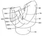
Fig. 3 is the schematic representation of the driving link of preferred embodiment hinge structure of the present invention;
Fig. 4 is the ssembly drawing of preferred embodiment hinge structure of the present invention;
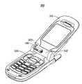
Fig. 5 is that preferred embodiment hinge structure of the present invention is applied to the schematic representation on the mobile phone;
Embodiment
The hinge structure of preferred embodiment of the present invention is applicable to folded form or the turning-lid type portable electron device (not shown) of a tool body and lid, and the specific embodiment of the invention is applied in mobile phone take it and is illustrated as example.
See also Fig. 1, thehinge structure 100 of preferred embodiment of the present invention comprisesmain shaft 10,follower 20,driving link 30,elastic component 40,sleeve 50 andpad 60.
Main shaft 10 is an elongated shaft, and it axially comprises an integrally formedhead 12 and anaxial region 14 successively.Thishead 12 is located at an end ofmain shaft 10, and thisaxial region 14 from thehead 12 middle part extends to a side, has draw-ingroove 142 on the end of thisaxial region 14 away fromhead 12.
Please in conjunction with consulting Fig. 2, thisfollower 20 is roughly a cylinder, and it comprises alip part 22 and a cam part 24.The outer circle wall of thislip part 22 is provided with twotangent planes 222, is used for matching with mobile phone body or lid.Thesefollower 20 central shafts are to having a throughhole 26, and this throughhole 26 connects thislip part 22 and cam part 24.Theaxial region 14 of thismain shaft 10 can be contained in the throughhole 26 of thisfollower 20, and itshead 12 is supported by lip part 22.Oppositely be provided with 2first camming surfaces 242 on the end face of these cam part 24 opposing flanges sections 22.Eachfirst camming surface 242 comprises an original surface connected to one another 2420, one protruding peaks 2422, one supporting surface 2423, one standstill faces, 2424, one junction surfaces 2425 and trench 2426 successively.This original surface 2420 is roughly a gently sloping surface, and it is slowly lifting highly from low to high.This protruding peak 2422 is arranged on this original surface 2420 ends, and is positioned at this original surface 2420 extreme higher positions.This supporting surface 2423 is an escarpmetnt, and its gradient is comparatively precipitous, and it extends highly from high in the end.This standstill face 2424 is connected to the end of this supporting surface 2423, and this standstill face 2424 is roughly a vertical plane.This junction surface 2425 is used for connecting this standstill face 2424 in this trench 2426.Offer a groove 244 on eachfirst camming surface 242, this groove 244 is opened in this supporting surface 2423, on standstill face 2424 and the junction surface 2425 and extend to this trench 2426 places.This groove 244 connects thesecamming surface 242 inboards, and connects with throughhole 26.
Please in conjunction with referring to Fig. 3, thisdriving link 30 is roughly a Cylindrical object, and it comprises anauxiliary section 32 and an extension part 34.Thisextension part 34 is extended by an end ofauxiliary section 32, and its external diameter is less than the external diameter of auxiliary section 32.These drivinglink 30 middle parts axially offer acircular channel 36 that runs throughauxiliary section 32 andextension part 34, are used for cooperating with theaxial region 14 of main shaft 10.The outer peripheral surface of theauxiliary section 32 of thisdriving link 30 is provided with two relative fins 38.Theseauxiliary section 32 1 ends are provided with two thesecond camming surfaces 320 that oppositely arrange, the shape of described thesecond camming surface 320 and thefirst camming surface 242 match, eachsecond camming surface 320 comprises anoriginal surface 3201, one protrudingpeak 3202, one supportingsurface 3203, one standstill face, 3204, one junction surfaces 3025 and a trench 3206.Thisoriginal surface 3201 is roughly a gently sloping surface, and it is slowly lifting highly from low to high.This protrudingpeak 3202 is arranged on thisoriginal surface 3201 ends, and is positioned at thisoriginal surface 3201 extreme higher positions.This supportingsurface 3203 is an escarpmetnt, and its gradient is comparatively precipitous, and it extends highly from high in the end.This standstill face 3204 is connected to the end of this supportingsurface 3203, and this standstill face 3204 is roughly a vertical plane.This junction surface 3025 is used for connecting this standstill face 3204 in this trench 3206.Aboss 322 is extended in 3204 adjacency channels, 36 places in the standstill face in each thesecond camming surface 320 inboard, the slightly curved wall shape of this boss 322.The groove 244 of thisfollower 20 provides a space for thisboss 322, avoids it to occur mutually to interfere.In addition, for avoiding thisboss 322 andfollower 20 mutually collision occurs when rotated, thisboss 322 is preferably with the supportingsurface 3203 smooth transition of thissecond camming surface 320 and is connected.
Elastic component 40 is a helical spring in the present embodiment, and its internal diameter is greater than the diameter of theaxial region 14 ofmain shaft 10, so thatelastic component 40 can be enclosed within on the main shaft 10.Theseelastic component 40 1 ends are set on theextension part 34 ofdriving link 30.
Thissleeve 50 is a hollow cylinder, and the external diameter of thisdriving link 30 and thiselastic component 40 is all less than the internal diameter ofsleeve 50, in order to can be contained in the sleeve 50.Thissleeve 50 has anopening end 52, half closed end 54.The diameter of thelip part 22 of thisfollower 20 is less than the diameter of thesesleeve 50opening ends 52, so that thislip part 22 can stretch in this sleeve 50.Has acenter hole 542 on this semiclosed end 54.A guidinggroove 58 is offered on parallel twoplanes 56 that are provided with on the outer circle wall of thissleeve 50 on eachplane 56, and thisplane 56 is used for matching with cell phone cover or body, and thefin 38 of thisdriving link 30 slidably is contained in the guidinggroove 58.
Pad 60 is made by metallic material, and in the present embodiment, thispad 60 is held on this draw-ingroove 142, thereby the element that is assemblied on themain shaft 10 can be fastened in one.
During assembling, see also Fig. 4,main shaft 10 is passed the throughhole 26 of thisfollower 20, so thatfollower 20 is set on the main shaft 10.Again drivinglink 30,elastic component 40 andsleeve 50 are installed on themain shaft 10 successively; Thesecond camming surface 320 on thisdriving link 30 is matched with thefirst camming surface 242 offollower 20,fin 38 is placed in the guidinggroove 58, one end ofelastic component 40 is set on theextension part 34 ofdriving link 30, the other end is held on the diapire ofsemiclosed end 54 ofsleeve 50, and an end that makesmain shaft 10 passes the throughhole 542 ofsleeve 50,pad 60 is fastened on the draw-ingroove 142, thereby above-mentioned hinge structure is assembled into one.
See also Fig. 5, this Hinge connectingstructure 100 is installed on portable electron device such as themobile phone 300, thismobile phone 300 comprises onlid 310 and the body 320.Theselid 310 1 ends have abutt bolt 312, and thesebody 320 1 ends have an attachment hole 322.Assemblehinge structure 100 of the present invention to themobile phone 300 time, atfirst hinge structure 100 is inserted in thebutt bolt 312 ofmobile phone 100, theplane 56 on thesleeve 50 nonrotationally is connected on the cell phone cover 310.Promote thehead 12 of thismain shaft 10, thishead 12 further promotesdriving link 20 and endwisely slips, and simultaneously, thiselastic component 30 is further compressed.Whenlip part 22 is placed insleeve 50 andbutt bolt 312 when interior fully, and theattachment hole 322 thatlip part 22 is aimed on thebody 320, after unclamping, thislip part 22 springs in thebody 320 automatically, nonrotationally is connected with theattachment hole 322 ofmobile phone body 320 by thetangent plane 222 on thelip part 12 on themain shaft 10.
When lid was closed fully, the protrudingpeak 3202 of thesecond camming surface 320 ofdriving link 30 was held in the original surface 2420 of thefirst camming surface 242 of servo-actuated 20, and thisboss 322 is placed in this groove 244.Elastic component 40 has certain precompression, and makes the two be in stable closed condition.
During opening cover, tolid 310 application of forces it is rotated relative tobody 320, thislid 310 drives drivinglink 30 bysleeve 50 and rotates, afterlid 310relative bodies 320 are opened several angle, protrudingpeak 3202 on thisdriving link 30 is slided along the original surface original surface 2420 of thefirst camming surface 242, and mobile compressionelastic piece 40, until the protruding peak 2422 of the first camming surface is crossed at the protrudingpeak 3202 on this driving link 30.Stop the application of force,elastic component 40 is compressed into the shortest, the accumulation elastic potential energy is maximum, this is a unstable state,discharge lid 310, the elastic potential energy ofelastic component 30 accumulations is slided rapidly drivinglink 30relative followers 20, this protrudingpeak 3202 slides along the supporting surface 2423 of thefirst camming surface 242, when this protrudingpeak 3202 slide intolid 310relative bodies 320 open 180 the degree after, this protrudingpeak 3202 slides into when closing on this 2424 place, standstill face, relative thesefollower 20 rotations ofboss 322 continuation of thisdriving link 30 realize surpassing 180 rotation, thereby the relative body of realization lid are opened above 180 degree.If thisboss 322 not, this protrudingpeak 3202 will after rotate 180 degree, namely begin to drop in the trench 2426 from standstill face 2424, and stop the rotation.When closing lid, above-mentioned operating process is opposite when opening, and does not describe in detail at this.
Onsecond camming surface 320 of hinge structure of the present invention by drivinglink 30boss 322 is set, make when drivinglink 30relative followers 20 and turn to 180 when spending, thisboss 322 can prevent that the protrudingpeak 3202 of thisdriving link 30 from falling into trench 2426, and continue to rotate, open angle can surpass 180 degree, open easily, easy to operate.
Be appreciated that the driving link of the specific embodiment of the invention and the camming surface on the follower, also other distortion can be arranged, can be arbitrary shape such as original surface.In addition, the camming surface design can according to the corresponding camming surface angle of the required angle design of opening of portable electron device, be adjusted such as the angle to original surface.
Be appreciated that lid can be in a stable position under the supporting of mobile phone body, the two position relationship is in steady state again, and this moment, lid was opened fully.
Be appreciated that thepad 60 of the specific embodiment of the invention and the combination ofmain shaft 10 can be expanded joint or welding.
Thefollower 20 that is appreciated that the specific embodiment of the invention also can be fixedly connected with axle.
Be appreciated that boss of the present invention is not limited to the shape of specific embodiment, as long as it satisfy can drive driving link and rotates relative to thisfollower 20.
Be appreciated that, the groove of this follower provides a space for this boss, to avoid it to occur mutually to interfere, therefore its setting position is not limited to be opened in supporting surface, standstill face and junction surface, it can be arranged on the needed single arbitrary face or its combination as required, can be opened in this supporting surface and standstill face such as this groove.
Be appreciated that this boss is not limited to this second camming surface inboard, it also can be arranged on the arbitrary position on the standstill face, and this boss shape also is not limited to the wall shape.
Be appreciated that, after relative the second camming surface of this first camming surface not only is limited to 180 degree rotations, this boss drives the relative follower of driving link and continues rotation, such as 170 degree or 190 degree, this boss drives the relative follower of driving link to be continued to rotate behind the rotatable predetermined angle of relative the second camming surface of this first camming surface.

Claims (8)

CN200910307640.6A2009-09-242009-09-24Hinge structure and portable electronic device applying sameExpired - Fee RelatedCN102032265B (en)

Priority Applications (3)

Application NumberPriority DateFiling DateTitle
CN200910307640.6ACN102032265B (en)2009-09-242009-09-24Hinge structure and portable electronic device applying same
US12/610,520US8245354B2 (en)2009-09-242009-11-02Hinge assembly for foldable electronic device
JP2010012078AJP5330281B2 (en)2009-09-242010-01-22 Hinge device and portable electronic device using the same

Applications Claiming Priority (1)

Application NumberPriority DateFiling DateTitle
CN200910307640.6ACN102032265B (en)2009-09-242009-09-24Hinge structure and portable electronic device applying same

Publications (2)

Publication NumberPublication Date
CN102032265A CN102032265A (en)2011-04-27
CN102032265Btrue CN102032265B (en)2013-01-09

Family

ID=43755311

Family Applications (1)

Application NumberTitlePriority DateFiling Date
CN200910307640.6AExpired - Fee RelatedCN102032265B (en)2009-09-242009-09-24Hinge structure and portable electronic device applying same

Country Status (3)

CountryLink
US (1)US8245354B2 (en)
JP (1)JP5330281B2 (en)
CN (1)CN102032265B (en)

Families Citing this family (14)

* Cited by examiner, † Cited by third party
Publication numberPriority datePublication dateAssigneeTitle
JP4908484B2 (en)*2008-11-272012-04-04三菱製鋼株式会社 Semi-auto hinge with rotation angle control mechanism
CN102207128A (en)*2010-03-302011-10-05深圳富泰宏精密工业有限公司Sleeve and hinge structure using sleeve
CN102221041B (en)*2010-04-192013-04-24深圳富泰宏精密工业有限公司Hinge structure and portable electronic device using same
CN201902441U (en)*2010-12-282011-07-20刘德文Rotating shaft device used for bag hanging device and bag hanging device
KR20130008729A (en)*2011-07-132013-01-23삼성전자주식회사Slim-type quick cradle for mobile phone
US9460029B2 (en)2012-03-022016-10-04Microsoft Technology Licensing, LlcPressure sensitive keys
CN102678738B (en)*2012-04-242015-07-08苏州佳世达电通有限公司Rotating shaft structure, support structure and electronic device
US20130300590A1 (en)2012-05-142013-11-14Paul Henry DietzAudio Feedback
TWI498491B (en)*2012-07-052015-09-01Wistron CorpOpening-closing apparatus and hinge device thereof
US9304549B2 (en)2013-03-282016-04-05Microsoft Technology Licensing, LlcHinge mechanism for rotatable component attachment
US9317072B2 (en)*2014-01-282016-04-19Microsoft Technology Licensing, LlcHinge mechanism with preset positions
US9447620B2 (en)2014-09-302016-09-20Microsoft Technology Licensing, LlcHinge mechanism with multiple preset positions
AT518621B1 (en)*2016-05-132018-10-15Blum Gmbh Julius actuator
ES2893253T3 (en)*2016-12-082022-02-08Southco latch with cover

Citations (4)

* Cited by examiner, † Cited by third party
Publication numberPriority datePublication dateAssigneeTitle
WO2003044974A1 (en)*2001-11-212003-05-30Phoenix Korea Co., Ltd.Hinge device
CN1773133A (en)*2004-11-122006-05-17松下电器产业株式会社 Switching device
KR100756914B1 (en)*2006-09-182007-09-07주식회사 엠투시스 Hinge Module for Mobile Phone
WO2008136613A1 (en)*2007-05-042008-11-13Laird Technologies Map Co., Ltd.Hinge module for folder type portable terminal

Family Cites Families (11)

* Cited by examiner, † Cited by third party
Publication numberPriority datePublication dateAssigneeTitle
JP3732619B2 (en)*1997-06-162006-01-05加藤電機株式会社 Hinge device
JP2003065321A (en)*2001-08-292003-03-05Strawberry CorporationHinge apparatus and electronic instrument using the same
JP2004232748A (en)*2003-01-302004-08-19Kato Electrical Mach Co LtdSmall opening-closing device
EP1589239A4 (en)*2003-01-312008-04-30Strawberry Corp KkHinge device and electronic device using hinge device
JP2004308872A (en)*2003-04-102004-11-04Matsushita Electric Ind Co Ltd Switchgear and electronic equipment using the same
TW573903U (en)*2003-06-062004-01-21Hon Hai Prec Ind Co LtdHinge of handy machine
JP2005249020A (en)*2004-03-032005-09-15Kazuo YamagamiPositioning mechanism and rotary support mechanism
CN2745324Y (en)*2004-10-052005-12-07鸿富锦精密工业(深圳)有限公司Hinge structure
JP2007271008A (en)*2006-03-312007-10-18Matsushita Electric Ind Co Ltd Switchgear
US7480961B2 (en)*2006-04-252009-01-27Chen Uei Precision Industry Co., Ltd.Miniature hinge
US7631398B1 (en)*2008-10-072009-12-15Leohab Enterprise Co., Ltd.Cam device for a hinge assembly

Patent Citations (4)

* Cited by examiner, † Cited by third party
Publication numberPriority datePublication dateAssigneeTitle
WO2003044974A1 (en)*2001-11-212003-05-30Phoenix Korea Co., Ltd.Hinge device
CN1773133A (en)*2004-11-122006-05-17松下电器产业株式会社 Switching device
KR100756914B1 (en)*2006-09-182007-09-07주식회사 엠투시스 Hinge Module for Mobile Phone
WO2008136613A1 (en)*2007-05-042008-11-13Laird Technologies Map Co., Ltd.Hinge module for folder type portable terminal

Also Published As

Publication numberPublication date
US20110067203A1 (en)2011-03-24
CN102032265A (en)2011-04-27
JP2011069488A (en)2011-04-07
US8245354B2 (en)2012-08-21
JP5330281B2 (en)2013-10-30

Similar Documents

PublicationPublication DateTitle
CN102032265B (en)Hinge structure and portable electronic device applying same
CN101929502B (en)Hinge structure and portable electronic device using same
CN101725628B (en)Hinge structure and portable electronic device applying same
CN102454692A (en)Hinge structure and portable electronic device using same
US11416039B2 (en)Complex moving/rotating pivot shaft device
CN102242761B (en)Hinge structure and portable electronic device therewith
US7694390B2 (en)Hinge mechanism for foldable electronic device
CN1948770B (en)Hinge structure and portable electron device using said hinge structure
CN102252014B (en)Hinge structure and portable electronic device applying same
CN100446646C (en)Hinge structure
US7299523B2 (en)Hinge mechanism for foldable electronic device
CN101563910A (en)Hinge construction for a mobile folding device
CN102486203B (en)Hinge structure and portable electronic device therewith
CN102454693B (en)Hinge structure and portable electronic device utilizing same
CN1916434B (en)Hinge structure, and portable electronic equipment of using the hinge structure
CN101566191A (en)Hinge structure and portable type electronic device applying same
CN102221041B (en)Hinge structure and portable electronic device using same
CN102116345B (en)Hinge structure
JP2008275139A (en)Two parallel shaft hinge module
CN219366568U (en)Hinge with one-key opening and free stopping functions
CN218625037U (en)Multi-friction-surface torsion mechanism of folding screen mobile terminal hinge
CN101737421A (en)Hinge mechanism and portable electronic device using same
CN101672324B (en)Hinge structure and portable electronic device applying same
CN102562781B (en)Hinge structure and portable electronic device with the hinge structure
US20050172455A1 (en)Hinge assembly with cammed driving

Legal Events

DateCodeTitleDescription
C06Publication
PB01Publication
C10Entry into substantive examination
SE01Entry into force of request for substantive examination
C14Grant of patent or utility model
GR01Patent grant
ASSSuccession or assignment of patent right

Owner name:NANTONG SHENLONG STRING + BELT CO., LTD.

Free format text:FORMER OWNER: BEIJING ZHONGCAI WYSE EDUCATION TECHNOLOGY CO., LTD.

Effective date:20141120

Owner name:BEIJING ZHONGCAI WYSE EDUCATION TECHNOLOGY CO., LT

Free format text:FORMER OWNER: SHENZHEN FUTAIHONG PRECISION INDUSTRY CO., LTD.

Effective date:20141120

C41Transfer of patent application or patent right or utility model
CORChange of bibliographic data

Free format text:CORRECT: ADDRESS; FROM: 100083 HAIDIAN, BEIJING TO: 226324 NANTONG, JIANGSU PROVINCE

Free format text:CORRECT: ADDRESS; FROM: 518109 SHENZHEN, GUANGDONG PROVINCE TO: 100083 HAIDIAN, BEIJING

TR01Transfer of patent right

Effective date of registration:20141120

Address after:226324, Nantong, Jiangsu province Tongzhou District two a town into the East Village

Patentee after:NANTONG SHENLONG STRING & BELT Co.,Ltd.

Address before:100083 Beijing Haidian District Zhongguancun Road No. 18 smartfortune International Building B706

Patentee before:Beijing Zhongcai Wyse Education Technology Co.,Ltd.

Effective date of registration:20141120

Address after:100083 Beijing Haidian District Zhongguancun Road No. 18 smartfortune International Building B706

Patentee after:Beijing Zhongcai Wyse Education Technology Co.,Ltd.

Address before:518109 F3 building, Foxconn science and Technology Industrial Park, Longhua Town, Shenzhen, Guangdong, A, China

Patentee before:Shenzhen Futaihong Precision Industry Co.,Ltd.

CF01Termination of patent right due to non-payment of annual fee

Granted publication date:20130109

Termination date:20180924


[8]ページ先頭

©2009-2025 Movatter.jp