CN102025148A - Power line network system with data relay function - Google Patents
Power line network system with data relay functionDownload PDFInfo
- Publication number
- CN102025148A CN102025148ACN2009101775088ACN200910177508ACN102025148ACN 102025148 ACN102025148 ACN 102025148ACN 2009101775088 ACN2009101775088 ACN 2009101775088ACN 200910177508 ACN200910177508 ACN 200910177508ACN 102025148 ACN102025148 ACN 102025148A
- Authority
- CN
- China
- Prior art keywords
- power line
- power
- data
- processor
- relay
- Prior art date
- Legal status (The legal status is an assumption and is not a legal conclusion. Google has not performed a legal analysis and makes no representation as to the accuracy of the status listed.)
- Pending
Links
- 238000012544monitoring processMethods0.000claimsabstractdescription62
- 238000012806monitoring deviceMethods0.000claimsabstractdescription28
- 230000005540biological transmissionEffects0.000claimsabstractdescription13
- 238000004891communicationMethods0.000claimsdescription27
- 238000001514detection methodMethods0.000claimsdescription17
- 238000006243chemical reactionMethods0.000claimsdescription11
- 238000000034methodMethods0.000claimsdescription4
- 238000010586diagramMethods0.000description6
- 238000011161developmentMethods0.000description2
- 230000005856abnormalityEffects0.000description1
- 230000008878couplingEffects0.000description1
- 238000010168coupling processMethods0.000description1
- 238000005859coupling reactionMethods0.000description1
- 238000005516engineering processMethods0.000description1
- 238000012986modificationMethods0.000description1
- 230000004048modificationEffects0.000description1
Images

Classifications
- H—ELECTRICITY
- H04—ELECTRIC COMMUNICATION TECHNIQUE
- H04B—TRANSMISSION
- H04B3/00—Line transmission systems
- H04B3/54—Systems for transmission via power distribution lines
- H04B3/58—Repeater circuits
- H—ELECTRICITY
- H04—ELECTRIC COMMUNICATION TECHNIQUE
- H04B—TRANSMISSION
- H04B3/00—Line transmission systems
- H04B3/54—Systems for transmission via power distribution lines
- H04B3/544—Setting up communications; Call and signalling arrangements
- H—ELECTRICITY
- H04—ELECTRIC COMMUNICATION TECHNIQUE
- H04B—TRANSMISSION
- H04B2203/00—Indexing scheme relating to line transmission systems
- H04B2203/54—Aspects of powerline communications not already covered by H04B3/54 and its subgroups
- H04B2203/5429—Applications for powerline communications
- H04B2203/5445—Local network
Landscapes
- Engineering & Computer Science (AREA)
- Power Engineering (AREA)
- Computer Networks & Wireless Communication (AREA)
- Signal Processing (AREA)
- Remote Monitoring And Control Of Power-Distribution Networks (AREA)
- Cable Transmission Systems, Equalization Of Radio And Reduction Of Echo (AREA)
Abstract
Description
Translated fromChinese技术领域technical field
本发明是关于一种电力线网络系统,尤指一种能确保数据传送正确性的电力线网络系统。The invention relates to a power line network system, especially a power line network system capable of ensuring the correctness of data transmission.
背景技术Background technique
电力线网络通讯通过既有布好的电力线作为数据传送的网络媒介,而不必另外布设网络线,因此电力线网络的发展有助于大范围,且非计算机型式的网络节点的相关应用。The power line network communication uses the existing power line as the network medium for data transmission, without laying out additional network lines. Therefore, the development of power line network is conducive to the application of large-scale and non-computer network nodes.
目前许多室内外的电气产品均朝向计算机化发展趋势加以设计,以增添更多功能提供使用的方便性,因此配合目前电力线网络技术,则能对这些电气产品更容易地进行远程监视或监控行为。举例来说,如内建有电力监视功能的LED路灯、具有自动读表功能的电表或信息家电等。At present, many indoor and outdoor electrical products are designed towards the development trend of computerization to add more functions to provide convenience of use. Therefore, with the current power line network technology, it is easier to remotely monitor or monitor these electrical products. For example, such as LED street lights with built-in power monitoring functions, electric meters with automatic meter reading functions, or information appliances.
然而,电力线网络虽可提供远程监视或监控功能,但利用既有电力线进行监视或监控数据的传输,容易受到噪声干扰,而且一旦远程与待监视本地端距离相差太远,则其中有用的数据讯号强度即容易衰减,造成不正确数据误读的缺点。However, although the power line network can provide remote monitoring or monitoring functions, the use of existing power lines for monitoring or monitoring data transmission is susceptible to noise interference, and once the distance between the remote and the local end to be monitored is too far, the useful data signal will be lost. The strength is easy to attenuate, causing the disadvantage of incorrect data misreading.
因此目前已有一种模拟式中继装置,主要于电力线的适当长度串接该模拟式中继装置,由于中继装置将电力讯号中的数据讯号予以放大,以确保本地及远程通过电力线进行数据传输的数据正确性。然而,模拟式中继装置必须将数据讯号予以放大,故必须串接于电力在线,然而于既有电力线串接任何装置都是耗工且费时的程序,而且应用于大功率电力线区域更必须使用高功率的电子组件,增加整个制作成本,因此对于确保电力线数据传输可靠度如何提升仍有待进一步提出有效解决方式。Therefore, there is currently an analog relay device, which is mainly connected in series with the appropriate length of the power line, because the relay device amplifies the data signal in the power signal to ensure local and remote data transmission through the power line data correctness. However, the analog relay device must amplify the data signal, so it must be connected in series with the power line. However, connecting any device in series with the existing power line is a labor-intensive and time-consuming procedure, and it must be used in areas with high-power power lines. High-power electronic components increase the overall production cost, so how to improve the reliability of power line data transmission still needs to be further proposed effective solutions.
发明内容Contents of the invention
本发明主要目的是提供一种具数据中继功能的电力线网络系统,能确保数据传送正确性,提高通讯的可靠度。The main purpose of the present invention is to provide a power line network system with data relay function, which can ensure the correctness of data transmission and improve the reliability of communication.
欲达上述目的所使用的主要技术手段是令该电力线网络系统包含有复数电力监控区域及至少一中继装置;其中复数电力监控区域是以电力线加以连接,以提供工作电力。又,各电力监控区域包含有至少一电力监控装置,而各中继装置则连接于两相邻的电力监控区域,即与两相邻的电力监控区域中的各电监控装置通过电力线相互连接;其中:The main technical means used to achieve the above purpose is to make the power line network system include multiple power monitoring areas and at least one relay device; wherein the multiple power monitoring areas are connected by power lines to provide working power. In addition, each power monitoring area includes at least one power monitoring device, and each relay device is connected to two adjacent power monitoring areas, that is, each power monitoring device in the two adjacent power monitoring areas is connected to each other through a power line; in:
上述第一中继单元通过电力线连接相邻电力监控区域的其中一电力监控区域的至少一电力监控装置,以将该至少一电力监控装置传送至电力在线的数据撷取出来后输出,又该第一中继单元接收第二中继单元传来的数据,经放大后以第一载波频带加以调变传送至电力在线;The above-mentioned first relay unit is connected to at least one power monitoring device in one of the adjacent power monitoring areas through a power line, so as to transmit the at least one power monitoring device to the power line to extract the data and output it, and the first A relay unit receives the data from the second relay unit, amplifies it, modulates it with the first carrier frequency band, and transmits it to the power line;
上述第二中继单元是与第一中继单元联机以收发数据,又该第二中继单元通过电力线连接相邻电力监控区域的其中一电力监控区域的至少一电力监控装置,以将该至少一电力监控装置传送至电力在线的数据撷取出来后输出至第一中继单元,又该第二中继单元接收第一中继单元传来的数据,经放大后以第二载波频带加以调变传送至电力在线,该第一及第二载频波并不相同。The above-mentioned second relay unit is connected to the first relay unit to send and receive data, and the second relay unit is connected to at least one power monitoring device in one of the adjacent power monitoring areas through a power line, so that the at least The data sent by a power monitoring device to the power line is extracted and output to the first relay unit, and the second relay unit receives the data from the first relay unit, amplifies it and modulates it with the second carrier frequency band. The first and second carrier frequency waves are different.
上述本发明中继装置利用二组不同调变频带的第一及第二中继单元,以将其各自邻近电力监控区的各电力监控点所发出的电力线讯号的数据予以撷取出,再由另一组中继单元接收后调变为第二频带后传送至另一电力监控区的电力在线,因此中继装置不必串接于电力在线;如此一来,不仅能确保数据传送不因传送距离过长而产生误读的问题,更能确保相邻不同电力监控区的讯号不会相互干扰。The above-mentioned relay device of the present invention utilizes two sets of first and second relay units with different modulation frequency bands to extract the data of the power line signals sent by the power monitoring points in their respective adjacent power monitoring areas, and then another A group of relay units receive it and adjust it to the second frequency band and then transmit it to the power line of another power monitoring area, so the relay device does not need to be connected in series with the power line; The problem of misreading due to long length can ensure that the signals of different adjacent power monitoring areas will not interfere with each other.
附图说明Description of drawings
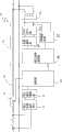
图1为本发明电力线网络通讯系统的系统架构图;1 is a system architecture diagram of the power line network communication system of the present invention;
图2为本发明应用于路灯电力监控的系统架构图;Fig. 2 is a system architecture diagram of the present invention applied to street lamp power monitoring;
图3为本发明中继装置的电路方块图;Fig. 3 is the circuit block diagram of relay device of the present invention;
图4为本发明电力监控装置的电路方块图。FIG. 4 is a circuit block diagram of the power monitoring device of the present invention.
附图中,各标号所代表的部件列表如下:In the accompanying drawings, the list of parts represented by each label is as follows:
(10)(10’)电力监控区域 (20)电力监控装置(10)(10’) Power monitoring area (20) Power monitoring device
(21)电力状态检知单元 (22)模拟数字转换单元(21) Power state detection unit (22) Analog-to-digital conversion unit
(23)处理器 (24)电力线通讯模块(23) Processor (24) Power line communication module
(241)数字信号处理器 (242)第一滤波器(241) digital signal processor (242) first filter
(243)变压器 (244)功率放大器(243)Transformer (244)Power Amplifier
(245)第二滤波器 (25)保护电路(245) Second filter (25) Protection circuit
(30)中继装置 (31)第一中继单元(30) Relay device (31) The first relay unit
(32)第二中继单元 (33)变压器(32) Second relay unit (33) Transformer
(34)数字信号处理器 (341)第一滤波器(34) Digital signal processor (341) The first filter
(342)第二滤波器 (343)功率放大器(342) Second Filter (343) Power Amplifier
(35)数字通讯接口 (40)路灯(35) Digital communication interface (40) Street lamp
(41)电力管理终端机 (111)电力线(41) Power management terminal (111) Power line
具体实施方式Detailed ways
请参阅图1所示,为本发明电力线网络系统的系统架构图,其包含有复数电力监控区域(10)(10’)及至少一中继装置(30);其中复数电力监控区域(10)(10’)以电力线网络(11)加以连接,以提供工作电力。又,各电力监控区域(10)(10’)包含有至少一电力监控装置(20),而各中继装置(30)则连接于两相邻的电力监控区域(10)(10’),即与两相邻的电力监控区域(10)(10’)中的各电监控装置(20)是通过电力线(111)相互连接。Please refer to Fig. 1, which is a system architecture diagram of the power line network system of the present invention, which includes a plurality of power monitoring areas (10) (10') and at least one relay device (30); wherein the plurality of power monitoring areas (10) (10') are connected with a power line network (11) to provide working power. In addition, each power monitoring area (10) (10') includes at least one power monitoring device (20), and each relay device (30) is connected to two adjacent power monitoring areas (10) (10'), That is, the electrical monitoring devices (20) in two adjacent electrical monitoring areas (10) (10') are connected to each other through power lines (111).
请配合参阅图2及图3所示,为本发明电力线网络系统应用于路灯(40)电力管理的一较佳实施例,其中各中继装置(30)包含有第一及第二中继单元(31)(32)。Please refer to Figure 2 and Figure 3, which is a preferred embodiment of the power line network system of the present invention applied to street lamp (40) power management, wherein each relay device (30) includes a first and a second relay unit (31)(32).
上述第一中继单元(31)是通过电力线(111)连接相邻电力监控区域(10)(10’)之其中一电力监控区域(10)的至少一电力监控装置(20),以将该至少一电力监控装置(20)传送至电力线(111)上的数据撷取出来,又该第一中继单元(31)接收第二中继单元(32)传来的数据,经放大后以第一载波频带(Frequency Band A;FBA)加以调变传送至电力线(111)上。The above-mentioned first relay unit (31) is connected to at least one power monitoring device (20) of one of the power monitoring areas (10) of the adjacent power monitoring areas (10) (10') through a power line (111), so that the The data transmitted from at least one power monitoring device (20) to the power line (111) is retrieved, and the first relay unit (31) receives the data transmitted from the second relay unit (32), and amplifies the data as the first relay unit (32). A carrier frequency band (Frequency Band A; FBA) is modulated and transmitted to the power line (111).
上述第二中继单元(32)是与第一中继单元(31)联机以收发数据,又该第二中继单元(32)通过电力线(111)连接相邻电力监控区域(10)(10’)的其中一电力监控区域(10’)的至少一电力监控装置(20),以将该至少一电力监控装置(20)传送至电力线(111)上的数据撷取出来后输出至第一中继单元(31),又该第二中继单元(32)接收第一中继单元(31)传来的数据,经放大后以第二载波频带(Frequency Band B;FAB)加以调变传送至电力线(111)上,该第一及第二载波频带并不相同。举例来说,第一频带可为60-90kHz,其中60及70kHz用作调变接收频率,而80及90kHz作为传送频率,反之亦可;又第二频带可为110-140kHz,其中110及140kHz用作调变接收频率,而130及140kHz作为传送频率,反之亦可;是以,当两相邻电力监控区域(10)(10’)的两监控装置(20)进行双向通讯时,其电力在线即包含有四组不同频率数据讯号,将讯号干扰状态降至最低。The above-mentioned second relay unit (32) is on-line with the first relay unit (31) to send and receive data, and the second relay unit (32) is connected to the adjacent power monitoring area (10) (10) through the power line (111). ') of at least one power monitoring device (20) in one of the power monitoring areas (10'), so that the at least one power monitoring device (20) is transmitted to the power line (111) to extract the data and output it to the first The relay unit (31), and the second relay unit (32) receives the data transmitted from the first relay unit (31), and transmits it after being amplified and modulated by the second carrier frequency band (Frequency Band B; FAB) On the power line (111), the first and second carrier frequency bands are different. For example, the first frequency band can be 60-90kHz, of which 60 and 70kHz are used as modulation receiving frequencies, while 80 and 90kHz are used as transmission frequencies, and vice versa; and the second frequency band can be 110-140kHz, of which 110 and 140kHz It is used to modulate the receiving frequency, and 130 and 140kHz are used as the transmitting frequency, and vice versa; therefore, when two monitoring devices (20) in two adjacent power monitoring areas (10) (10') perform two-way communication, their power Online includes four sets of data signals with different frequencies to minimize signal interference.
上述第一及第二中继单元(31)(32)分别包含有:The above-mentioned first and second relay units (31) (32) respectively include:
一变压器(33),用以耦合连接至该电力线(111);a transformer (33) for coupling to the power line (111);
一数字信号处理器(34),其输入端是通过二第一滤波器(341)电连接至该变压器(33),以接收来自电力线(111)的二组不同调变频率的外部数据讯号,又该数字信号处理器(34)的输出端是通过二第二滤波器(342)及一功率放大器(343)连接至该变压器(33),以将数据加以处理并调变,由变压器(33)耦合至电力线(111)对外传送二组不同调变频率的数据讯号;其中各第一滤波器(341)为一带通滤波器,而其带通频率分别对应二组不同的接收频率(F1)(F2),而各第二滤波器(342)为一低通滤波器,其低通频率对应二组不同的传送收频率;及A digital signal processor (34), whose input terminal is electrically connected to the transformer (33) through two first filters (341), so as to receive two sets of external data signals with different modulation frequencies from the power line (111), And the output end of this digital signal processor (34) is to be connected to this transformer (33) by two second filters (342) and a power amplifier (343), so that data is processed and modulated, by transformer (33 ) coupled to the power line (111) to transmit two sets of data signals with different modulation frequencies; wherein each first filter (341) is a band-pass filter, and its band-pass frequency corresponds to two sets of different receiving frequencies (F1) (F2), and each second filter (342) is a low-pass filter, and its low-pass frequency corresponds to two groups of different transmission and reception frequencies; and
一数字通讯接口(35),是供相同通讯标准的数字通讯接口连接,以收发数据;在本实施例中该数字通讯接口(35)为UART,也可为RS232或USB等串行通讯接口,且该UART接口直接整合于数字信号处理器(34)内。A digital communication interface (35), is to be connected for the digital communication interface of identical communication standard, to send and receive data; In the present embodiment, this digital communication interface (35) is UART, also can be serial communication interfaces such as RS232 or USB, And the UART interface is directly integrated in the digital signal processor (34).
本发明中继装置(30)利用二组调变频带(FBA/FBB)不同的第一及第二中继单元(31)(32),以将其各自邻近电力监控区(10)(10’)的各电力监控点所发出的电力线讯号的数据予以撷取出,再由另一组中继单元(32)(31)接收后调变为另一频带后传送至另一电力监控区的电力线(111)上;如此一来,不仅能确保数据传送不因传送距离过长而产生误读的问题,更能确保相邻不同电力监控区的讯号不会相互干扰。The relay device (30) of the present invention utilizes two sets of first and second relay units (31) (32) with different modulation frequency bands (FBA/FBB) to connect them to the respective adjacent power monitoring areas (10) (10' ) The data of the power line signal sent by each power monitoring point in ) is extracted, and then received by another group of relay units (32) (31), modulated into another frequency band, and then sent to the power line of another power monitoring area ( 111); in this way, it can not only ensure that the data transmission will not cause misreading due to the long transmission distance, but also ensure that the signals of different adjacent power monitoring areas will not interfere with each other.
请同时参阅图2及图4所示,为本发明应用于路灯(40)的电力监控装置的电路方块图,其包含有:Please refer to Fig. 2 and Fig. 4 at the same time, which is a circuit block diagram of a power monitoring device applied to a street lamp (40) of the present invention, which includes:
一电力状态检知单元(25),耦接至电力线(111)上,取得电力线(111)的电压及电流状态后输出;A power state detection unit (25), coupled to the power line (111), obtains the voltage and current state of the power line (111) and outputs it;
一模拟数字转换单元(22),连接至该电力状态检知单元(21)的输出端,以转换其模拟检知讯号为数字讯号后输出;An analog-to-digital conversion unit (22), connected to the output terminal of the power state detection unit (21), to convert the analog detection signal into a digital signal for output;
一处理器(23),连接至该模拟数字转换单元(22)的输出端,以取得电压及电流数值;a processor (23), connected to the output terminal of the analog-to-digital conversion unit (22), to obtain voltage and current values;
一电力线通讯模块(24),连接至该处理器(23),以取得该处理器(23)输出电压及电流数值,将其调变成模拟讯号后加载电力线(111)中,又该电力线通讯模块(24)也接收电力线(111)上的模拟讯号,并将其中数据撷取出来后输出至处理器(23)中;其中该调变频带对应其所属电力监控区对应中继单元的调变频带(FBA/FBB);在本实施例中该电力线通讯模块(24)架构与第一及第二中继单元相同,均包含有一数字信号处理器(241)、第一滤波器(242)、一变压器(243)、一功率放大器(244)及一第二滤波器(245);及A power line communication module (24), connected to the processor (23), to obtain the output voltage and current value of the processor (23), convert it into an analog signal and load it into the power line (111), and the power line communication The module (24) also receives the analog signal on the power line (111), and outputs the data after it is extracted to the processor (23); wherein the modulation frequency band corresponds to the modulation frequency of the corresponding relay unit in the power monitoring area to which it belongs band (FBA/FBB); in this embodiment, the structure of the power line communication module (24) is the same as that of the first and second relay units, and both include a digital signal processor (241), a first filter (242), a transformer (243), a power amplifier (244) and a second filter (245); and
一保护电路(25),串接于电力线(111)上,其控制端连接至该处理器(23)的输出端,在处理器依据接收外部传来数据资料启闭该保护电路(25);在本实施例中该保护电路(25)为一电力开关。A protection circuit (25), connected in series on the power line (111), its control end connected to the output end of the processor (23), the processor opens and closes the protection circuit (25) according to receiving data from the outside; In this embodiment, the protection circuit (25) is a power switch.
上述各路灯的电力监控装置(20)是通过电力状态检知单元(21)检知路灯(40)的用电状态,并通过电力通讯模块(24)对外传送电力数据至电力线(111)时,若配合电力管理终端机(41)设置在其它电力监控区域(10’),则会由邻近路灯(40)所属电力监控区域(10)的中继装置(30)加以接收,并由其中对应调变频带的中继单元将其中电力数据撷取后由另一中继单元调变成另一频带讯号后加载其它电力监控区域,最终传送至电力管理终端机(41)。又该电力管理终端机(41)如判断特定路灯(40)有电力异常,则也可通过电力线网络(11)将断电命令数据调变后加载电力线(111)中,同样通过中继装置(30)处理而顺利将此一断电命令传送至对应路灯(40)的电力监控装置(20)的处理器(23),再由处理器(23)判继此一断电命令后启动该保护电路,将路灯的电力暂时中断。The power monitoring device (20) of the above-mentioned street lamps detects the power consumption status of the street lamps (40) through the power state detection unit (21), and transmits power data to the power line (111) through the power communication module (24), If the power management terminal (41) is installed in other power monitoring areas (10'), it will be received by the relay device (30) of the power monitoring area (10) adjacent to the street lamp (40), and the corresponding adjustment The relay unit of the variable frequency band converts the power data acquired by another relay unit into another frequency band signal, loads it into other power monitoring areas, and finally transmits it to the power management terminal (41). And if the power management terminal (41) judges that the specific street lamp (40) has power abnormality, it can also load the power-off command data into the power line (111) after modulation through the power line network (11), and also through the relay device ( 30) process and successfully transmit this power-off command to the processor (23) of the power monitoring device (20) corresponding to the street lamp (40), and then start the protection after judging by the processor (23) following this power-off command circuit that temporarily interrupts power to street lights.
诚如上述,本发明主要以数字方式进行电力线数据讯号的读取,再以不同频带载波频带加载电力线中,由于数据经由中继装置的处理后,电力线网络上距离相距过远的电力监控点均能正确地取得相互的数据,避免因为电力线天生噪声干扰情况多而造成数据误读的问题;此外,本发明的中继装置不必串接于电力在线,故可免除变更既有电力线的耗时费力的步骤;因此,本发明能提供如路灯或电表等电力监控点的应用。As mentioned above, the present invention mainly reads the power line data signal in a digital way, and then loads the power line with different frequency band carrier frequency bands. After the data is processed by the relay device, the power monitoring points that are too far apart on the power line network The mutual data can be obtained correctly, and the problem of data misreading caused by the natural noise interference of the power line is avoided; in addition, the relay device of the present invention does not need to be connected in series with the power line, so it can avoid the time-consuming and laborious modification of the existing power line steps; therefore, the present invention can provide applications such as power monitoring points such as street lamps or electric meters.
Claims (10)
Translated fromChinesePriority Applications (2)
| Application Number | Priority Date | Filing Date | Title |
|---|---|---|---|
| CN2009101775088ACN102025148A (en) | 2009-09-14 | 2009-09-14 | Power line network system with data relay function |
| US12/572,657US8248229B2 (en) | 2009-09-14 | 2009-10-02 | Powerline network system having data relay function |
Applications Claiming Priority (2)
| Application Number | Priority Date | Filing Date | Title |
|---|---|---|---|
| CN2009101775088ACN102025148A (en) | 2009-09-14 | 2009-09-14 | Power line network system with data relay function |
| US12/572,657US8248229B2 (en) | 2009-09-14 | 2009-10-02 | Powerline network system having data relay function |
Publications (1)
| Publication Number | Publication Date |
|---|---|
| CN102025148Atrue CN102025148A (en) | 2011-04-20 |
Family
ID=50138030
Family Applications (1)
| Application Number | Title | Priority Date | Filing Date |
|---|---|---|---|
| CN2009101775088APendingCN102025148A (en) | 2009-09-14 | 2009-09-14 | Power line network system with data relay function |
Country Status (2)
| Country | Link |
|---|---|
| US (1) | US8248229B2 (en) |
| CN (1) | CN102025148A (en) |
Cited By (3)
| Publication number | Priority date | Publication date | Assignee | Title |
|---|---|---|---|---|
| CN104460555A (en)* | 2013-09-22 | 2015-03-25 | 丘玓 | Intelligent data fusion control cloud device and data transmission control method thereof |
| CN107770782A (en)* | 2016-08-22 | 2018-03-06 | 中国电信股份有限公司 | Signal trunking method, relay and electric power signal transfer approach and system |
| CN109981143A (en)* | 2019-02-26 | 2019-07-05 | 彭浩明 | Power carrier wave communication device, breaker, socket and system |
Families Citing this family (117)
| Publication number | Priority date | Publication date | Assignee | Title |
|---|---|---|---|---|
| EP2608417B1 (en)* | 2011-12-23 | 2020-07-22 | Power Plus Communications AG | Method and system for monitoring the condition of a supply grid |
| DE102012217808A1 (en)* | 2012-09-28 | 2014-04-03 | Lufthansa Technik Ag | Communication system and method for an aircraft |
| US9525524B2 (en) | 2013-05-31 | 2016-12-20 | At&T Intellectual Property I, L.P. | Remote distributed antenna system |
| US9999038B2 (en) | 2013-05-31 | 2018-06-12 | At&T Intellectual Property I, L.P. | Remote distributed antenna system |
| US8897697B1 (en) | 2013-11-06 | 2014-11-25 | At&T Intellectual Property I, Lp | Millimeter-wave surface-wave communications |
| US9768833B2 (en) | 2014-09-15 | 2017-09-19 | At&T Intellectual Property I, L.P. | Method and apparatus for sensing a condition in a transmission medium of electromagnetic waves |
| US10063280B2 (en) | 2014-09-17 | 2018-08-28 | At&T Intellectual Property I, L.P. | Monitoring and mitigating conditions in a communication network |
| CN104268114A (en)* | 2014-09-26 | 2015-01-07 | 合肥华耀电子工业有限公司 | Power source measurement and control system and control method thereof |
| US9615269B2 (en) | 2014-10-02 | 2017-04-04 | At&T Intellectual Property I, L.P. | Method and apparatus that provides fault tolerance in a communication network |
| US9685992B2 (en) | 2014-10-03 | 2017-06-20 | At&T Intellectual Property I, L.P. | Circuit panel network and methods thereof |
| US9503189B2 (en) | 2014-10-10 | 2016-11-22 | At&T Intellectual Property I, L.P. | Method and apparatus for arranging communication sessions in a communication system |
| US9973299B2 (en) | 2014-10-14 | 2018-05-15 | At&T Intellectual Property I, L.P. | Method and apparatus for adjusting a mode of communication in a communication network |
| US9769020B2 (en) | 2014-10-21 | 2017-09-19 | At&T Intellectual Property I, L.P. | Method and apparatus for responding to events affecting communications in a communication network |
| US9780834B2 (en) | 2014-10-21 | 2017-10-03 | At&T Intellectual Property I, L.P. | Method and apparatus for transmitting electromagnetic waves |
| US9312919B1 (en) | 2014-10-21 | 2016-04-12 | At&T Intellectual Property I, Lp | Transmission device with impairment compensation and methods for use therewith |
| US9653770B2 (en) | 2014-10-21 | 2017-05-16 | At&T Intellectual Property I, L.P. | Guided wave coupler, coupling module and methods for use therewith |
| US9577306B2 (en) | 2014-10-21 | 2017-02-21 | At&T Intellectual Property I, L.P. | Guided-wave transmission device and methods for use therewith |
| US9627768B2 (en) | 2014-10-21 | 2017-04-18 | At&T Intellectual Property I, L.P. | Guided-wave transmission device with non-fundamental mode propagation and methods for use therewith |
| US9544006B2 (en) | 2014-11-20 | 2017-01-10 | At&T Intellectual Property I, L.P. | Transmission device with mode division multiplexing and methods for use therewith |
| US9997819B2 (en) | 2015-06-09 | 2018-06-12 | At&T Intellectual Property I, L.P. | Transmission medium and method for facilitating propagation of electromagnetic waves via a core |
| US9742462B2 (en) | 2014-12-04 | 2017-08-22 | At&T Intellectual Property I, L.P. | Transmission medium and communication interfaces and methods for use therewith |
| US10009067B2 (en) | 2014-12-04 | 2018-06-26 | At&T Intellectual Property I, L.P. | Method and apparatus for configuring a communication interface |
| US10243784B2 (en) | 2014-11-20 | 2019-03-26 | At&T Intellectual Property I, L.P. | System for generating topology information and methods thereof |
| US9954287B2 (en) | 2014-11-20 | 2018-04-24 | At&T Intellectual Property I, L.P. | Apparatus for converting wireless signals and electromagnetic waves and methods thereof |
| US9461706B1 (en) | 2015-07-31 | 2016-10-04 | At&T Intellectual Property I, Lp | Method and apparatus for exchanging communication signals |
| US9800327B2 (en) | 2014-11-20 | 2017-10-24 | At&T Intellectual Property I, L.P. | Apparatus for controlling operations of a communication device and methods thereof |
| US9876570B2 (en) | 2015-02-20 | 2018-01-23 | At&T Intellectual Property I, Lp | Guided-wave transmission device with non-fundamental mode propagation and methods for use therewith |
| US9749013B2 (en) | 2015-03-17 | 2017-08-29 | At&T Intellectual Property I, L.P. | Method and apparatus for reducing attenuation of electromagnetic waves guided by a transmission medium |
| US9705561B2 (en) | 2015-04-24 | 2017-07-11 | At&T Intellectual Property I, L.P. | Directional coupling device and methods for use therewith |
| US10224981B2 (en) | 2015-04-24 | 2019-03-05 | At&T Intellectual Property I, Lp | Passive electrical coupling device and methods for use therewith |
| US9793954B2 (en) | 2015-04-28 | 2017-10-17 | At&T Intellectual Property I, L.P. | Magnetic coupling device and methods for use therewith |
| US9748626B2 (en) | 2015-05-14 | 2017-08-29 | At&T Intellectual Property I, L.P. | Plurality of cables having different cross-sectional shapes which are bundled together to form a transmission medium |
| US9490869B1 (en) | 2015-05-14 | 2016-11-08 | At&T Intellectual Property I, L.P. | Transmission medium having multiple cores and methods for use therewith |
| US9871282B2 (en) | 2015-05-14 | 2018-01-16 | At&T Intellectual Property I, L.P. | At least one transmission medium having a dielectric surface that is covered at least in part by a second dielectric |
| US10650940B2 (en) | 2015-05-15 | 2020-05-12 | At&T Intellectual Property I, L.P. | Transmission medium having a conductive material and methods for use therewith |
| US9917341B2 (en) | 2015-05-27 | 2018-03-13 | At&T Intellectual Property I, L.P. | Apparatus and method for launching electromagnetic waves and for modifying radial dimensions of the propagating electromagnetic waves |
| US10756805B2 (en) | 2015-06-03 | 2020-08-25 | At&T Intellectual Property I, L.P. | Client node device with frequency conversion and methods for use therewith |
| US9912381B2 (en) | 2015-06-03 | 2018-03-06 | At&T Intellectual Property I, Lp | Network termination and methods for use therewith |
| US10812174B2 (en)* | 2015-06-03 | 2020-10-20 | At&T Intellectual Property I, L.P. | Client node device and methods for use therewith |
| US9866309B2 (en) | 2015-06-03 | 2018-01-09 | At&T Intellectual Property I, Lp | Host node device and methods for use therewith |
| US10348391B2 (en) | 2015-06-03 | 2019-07-09 | At&T Intellectual Property I, L.P. | Client node device with frequency conversion and methods for use therewith |
| US9913139B2 (en) | 2015-06-09 | 2018-03-06 | At&T Intellectual Property I, L.P. | Signal fingerprinting for authentication of communicating devices |
| US9820146B2 (en) | 2015-06-12 | 2017-11-14 | At&T Intellectual Property I, L.P. | Method and apparatus for authentication and identity management of communicating devices |
| US9640850B2 (en) | 2015-06-25 | 2017-05-02 | At&T Intellectual Property I, L.P. | Methods and apparatus for inducing a non-fundamental wave mode on a transmission medium |
| US9865911B2 (en) | 2015-06-25 | 2018-01-09 | At&T Intellectual Property I, L.P. | Waveguide system for slot radiating first electromagnetic waves that are combined into a non-fundamental wave mode second electromagnetic wave on a transmission medium |
| US9509415B1 (en) | 2015-06-25 | 2016-11-29 | At&T Intellectual Property I, L.P. | Methods and apparatus for inducing a fundamental wave mode on a transmission medium |
| US10205655B2 (en) | 2015-07-14 | 2019-02-12 | At&T Intellectual Property I, L.P. | Apparatus and methods for communicating utilizing an antenna array and multiple communication paths |
| US9847566B2 (en) | 2015-07-14 | 2017-12-19 | At&T Intellectual Property I, L.P. | Method and apparatus for adjusting a field of a signal to mitigate interference |
| US9628116B2 (en) | 2015-07-14 | 2017-04-18 | At&T Intellectual Property I, L.P. | Apparatus and methods for transmitting wireless signals |
| US10044409B2 (en) | 2015-07-14 | 2018-08-07 | At&T Intellectual Property I, L.P. | Transmission medium and methods for use therewith |
| US9882257B2 (en) | 2015-07-14 | 2018-01-30 | At&T Intellectual Property I, L.P. | Method and apparatus for launching a wave mode that mitigates interference |
| US9853342B2 (en) | 2015-07-14 | 2017-12-26 | At&T Intellectual Property I, L.P. | Dielectric transmission medium connector and methods for use therewith |
| US10148016B2 (en) | 2015-07-14 | 2018-12-04 | At&T Intellectual Property I, L.P. | Apparatus and methods for communicating utilizing an antenna array |
| US10090606B2 (en) | 2015-07-15 | 2018-10-02 | At&T Intellectual Property I, L.P. | Antenna system with dielectric array and methods for use therewith |
| US9871283B2 (en) | 2015-07-23 | 2018-01-16 | At&T Intellectual Property I, Lp | Transmission medium having a dielectric core comprised of plural members connected by a ball and socket configuration |
| US9912027B2 (en) | 2015-07-23 | 2018-03-06 | At&T Intellectual Property I, L.P. | Method and apparatus for exchanging communication signals |
| US9948333B2 (en) | 2015-07-23 | 2018-04-17 | At&T Intellectual Property I, L.P. | Method and apparatus for wireless communications to mitigate interference |
| US9749053B2 (en) | 2015-07-23 | 2017-08-29 | At&T Intellectual Property I, L.P. | Node device, repeater and methods for use therewith |
| US9967173B2 (en) | 2015-07-31 | 2018-05-08 | At&T Intellectual Property I, L.P. | Method and apparatus for authentication and identity management of communicating devices |
| US9735833B2 (en) | 2015-07-31 | 2017-08-15 | At&T Intellectual Property I, L.P. | Method and apparatus for communications management in a neighborhood network |
| US9904535B2 (en) | 2015-09-14 | 2018-02-27 | At&T Intellectual Property I, L.P. | Method and apparatus for distributing software |
| US9769128B2 (en) | 2015-09-28 | 2017-09-19 | At&T Intellectual Property I, L.P. | Method and apparatus for encryption of communications over a network |
| US9729197B2 (en) | 2015-10-01 | 2017-08-08 | At&T Intellectual Property I, L.P. | Method and apparatus for communicating network management traffic over a network |
| US9876264B2 (en) | 2015-10-02 | 2018-01-23 | At&T Intellectual Property I, Lp | Communication system, guided wave switch and methods for use therewith |
| US10355367B2 (en) | 2015-10-16 | 2019-07-16 | At&T Intellectual Property I, L.P. | Antenna structure for exchanging wireless signals |
| US9860075B1 (en) | 2016-08-26 | 2018-01-02 | At&T Intellectual Property I, L.P. | Method and communication node for broadband distribution |
| US10811767B2 (en) | 2016-10-21 | 2020-10-20 | At&T Intellectual Property I, L.P. | System and dielectric antenna with convex dielectric radome |
| US10312567B2 (en) | 2016-10-26 | 2019-06-04 | At&T Intellectual Property I, L.P. | Launcher with planar strip antenna and methods for use therewith |
| US10225025B2 (en) | 2016-11-03 | 2019-03-05 | At&T Intellectual Property I, L.P. | Method and apparatus for detecting a fault in a communication system |
| US10498044B2 (en) | 2016-11-03 | 2019-12-03 | At&T Intellectual Property I, L.P. | Apparatus for configuring a surface of an antenna |
| US10291334B2 (en) | 2016-11-03 | 2019-05-14 | At&T Intellectual Property I, L.P. | System for detecting a fault in a communication system |
| US10224634B2 (en) | 2016-11-03 | 2019-03-05 | At&T Intellectual Property I, L.P. | Methods and apparatus for adjusting an operational characteristic of an antenna |
| US10340603B2 (en) | 2016-11-23 | 2019-07-02 | At&T Intellectual Property I, L.P. | Antenna system having shielded structural configurations for assembly |
| US10090594B2 (en) | 2016-11-23 | 2018-10-02 | At&T Intellectual Property I, L.P. | Antenna system having structural configurations for assembly |
| US10535928B2 (en) | 2016-11-23 | 2020-01-14 | At&T Intellectual Property I, L.P. | Antenna system and methods for use therewith |
| US10340601B2 (en) | 2016-11-23 | 2019-07-02 | At&T Intellectual Property I, L.P. | Multi-antenna system and methods for use therewith |
| US10178445B2 (en) | 2016-11-23 | 2019-01-08 | At&T Intellectual Property I, L.P. | Methods, devices, and systems for load balancing between a plurality of waveguides |
| US10361489B2 (en) | 2016-12-01 | 2019-07-23 | At&T Intellectual Property I, L.P. | Dielectric dish antenna system and methods for use therewith |
| US10305190B2 (en) | 2016-12-01 | 2019-05-28 | At&T Intellectual Property I, L.P. | Reflecting dielectric antenna system and methods for use therewith |
| US10727599B2 (en) | 2016-12-06 | 2020-07-28 | At&T Intellectual Property I, L.P. | Launcher with slot antenna and methods for use therewith |
| US10819035B2 (en) | 2016-12-06 | 2020-10-27 | At&T Intellectual Property I, L.P. | Launcher with helical antenna and methods for use therewith |
| US10135145B2 (en) | 2016-12-06 | 2018-11-20 | At&T Intellectual Property I, L.P. | Apparatus and methods for generating an electromagnetic wave along a transmission medium |
| US10382976B2 (en) | 2016-12-06 | 2019-08-13 | At&T Intellectual Property I, L.P. | Method and apparatus for managing wireless communications based on communication paths and network device positions |
| US9927517B1 (en) | 2016-12-06 | 2018-03-27 | At&T Intellectual Property I, L.P. | Apparatus and methods for sensing rainfall |
| US10020844B2 (en) | 2016-12-06 | 2018-07-10 | T&T Intellectual Property I, L.P. | Method and apparatus for broadcast communication via guided waves |
| US10439675B2 (en) | 2016-12-06 | 2019-10-08 | At&T Intellectual Property I, L.P. | Method and apparatus for repeating guided wave communication signals |
| US10694379B2 (en) | 2016-12-06 | 2020-06-23 | At&T Intellectual Property I, L.P. | Waveguide system with device-based authentication and methods for use therewith |
| US10755542B2 (en) | 2016-12-06 | 2020-08-25 | At&T Intellectual Property I, L.P. | Method and apparatus for surveillance via guided wave communication |
| US10637149B2 (en) | 2016-12-06 | 2020-04-28 | At&T Intellectual Property I, L.P. | Injection molded dielectric antenna and methods for use therewith |
| US10326494B2 (en) | 2016-12-06 | 2019-06-18 | At&T Intellectual Property I, L.P. | Apparatus for measurement de-embedding and methods for use therewith |
| US9893795B1 (en) | 2016-12-07 | 2018-02-13 | At&T Intellectual Property I, Lp | Method and repeater for broadband distribution |
| US10446936B2 (en) | 2016-12-07 | 2019-10-15 | At&T Intellectual Property I, L.P. | Multi-feed dielectric antenna system and methods for use therewith |
| US10359749B2 (en) | 2016-12-07 | 2019-07-23 | At&T Intellectual Property I, L.P. | Method and apparatus for utilities management via guided wave communication |
| US10243270B2 (en) | 2016-12-07 | 2019-03-26 | At&T Intellectual Property I, L.P. | Beam adaptive multi-feed dielectric antenna system and methods for use therewith |
| US10139820B2 (en) | 2016-12-07 | 2018-11-27 | At&T Intellectual Property I, L.P. | Method and apparatus for deploying equipment of a communication system |
| US10389029B2 (en) | 2016-12-07 | 2019-08-20 | At&T Intellectual Property I, L.P. | Multi-feed dielectric antenna system with core selection and methods for use therewith |
| US10168695B2 (en) | 2016-12-07 | 2019-01-01 | At&T Intellectual Property I, L.P. | Method and apparatus for controlling an unmanned aircraft |
| US10547348B2 (en) | 2016-12-07 | 2020-01-28 | At&T Intellectual Property I, L.P. | Method and apparatus for switching transmission mediums in a communication system |
| US10027397B2 (en) | 2016-12-07 | 2018-07-17 | At&T Intellectual Property I, L.P. | Distributed antenna system and methods for use therewith |
| US10103422B2 (en) | 2016-12-08 | 2018-10-16 | At&T Intellectual Property I, L.P. | Method and apparatus for mounting network devices |
| US10530505B2 (en) | 2016-12-08 | 2020-01-07 | At&T Intellectual Property I, L.P. | Apparatus and methods for launching electromagnetic waves along a transmission medium |
| US10326689B2 (en) | 2016-12-08 | 2019-06-18 | At&T Intellectual Property I, L.P. | Method and system for providing alternative communication paths |
| US10938108B2 (en) | 2016-12-08 | 2021-03-02 | At&T Intellectual Property I, L.P. | Frequency selective multi-feed dielectric antenna system and methods for use therewith |
| US10916969B2 (en) | 2016-12-08 | 2021-02-09 | At&T Intellectual Property I, L.P. | Method and apparatus for providing power using an inductive coupling |
| US10411356B2 (en) | 2016-12-08 | 2019-09-10 | At&T Intellectual Property I, L.P. | Apparatus and methods for selectively targeting communication devices with an antenna array |
| US9998870B1 (en) | 2016-12-08 | 2018-06-12 | At&T Intellectual Property I, L.P. | Method and apparatus for proximity sensing |
| US10601494B2 (en) | 2016-12-08 | 2020-03-24 | At&T Intellectual Property I, L.P. | Dual-band communication device and method for use therewith |
| US9911020B1 (en) | 2016-12-08 | 2018-03-06 | At&T Intellectual Property I, L.P. | Method and apparatus for tracking via a radio frequency identification device |
| US10069535B2 (en) | 2016-12-08 | 2018-09-04 | At&T Intellectual Property I, L.P. | Apparatus and methods for launching electromagnetic waves having a certain electric field structure |
| US10777873B2 (en) | 2016-12-08 | 2020-09-15 | At&T Intellectual Property I, L.P. | Method and apparatus for mounting network devices |
| US10389037B2 (en) | 2016-12-08 | 2019-08-20 | At&T Intellectual Property I, L.P. | Apparatus and methods for selecting sections of an antenna array and use therewith |
| US10264586B2 (en) | 2016-12-09 | 2019-04-16 | At&T Mobility Ii Llc | Cloud-based packet controller and methods for use therewith |
| US10340983B2 (en) | 2016-12-09 | 2019-07-02 | At&T Intellectual Property I, L.P. | Method and apparatus for surveying remote sites via guided wave communications |
| US9838896B1 (en) | 2016-12-09 | 2017-12-05 | At&T Intellectual Property I, L.P. | Method and apparatus for assessing network coverage |
| US9973940B1 (en) | 2017-02-27 | 2018-05-15 | At&T Intellectual Property I, L.P. | Apparatus and methods for dynamic impedance matching of a guided wave launcher |
| US10298293B2 (en) | 2017-03-13 | 2019-05-21 | At&T Intellectual Property I, L.P. | Apparatus of communication utilizing wireless network devices |
| CN116827390B (en)* | 2023-06-09 | 2024-07-23 | 国网吉林省电力有限公司长春供电公司 | Communication data regulation and control method and system based on analog optical fiber communication |
Citations (4)
| Publication number | Priority date | Publication date | Assignee | Title |
|---|---|---|---|---|
| CN1564475A (en)* | 2004-03-23 | 2005-01-12 | 中国电力科学研究院 | Multi-speed hybrid power line broadband access system and relay thereof |
| WO2006134655A1 (en)* | 2005-06-16 | 2006-12-21 | Mitsubishi Denki Kabushiki Kaisha | Power line propagation communication system |
| CN101188890A (en)* | 2007-11-29 | 2008-05-28 | 聊城大学 | A street light energy saving control system |
| CN101399565A (en)* | 2007-09-07 | 2009-04-01 | 康舒科技股份有限公司 | Network real-time power monitoring system |
Family Cites Families (4)
| Publication number | Priority date | Publication date | Assignee | Title |
|---|---|---|---|---|
| US3927404A (en)* | 1973-10-18 | 1975-12-16 | Standard Electric Time Corp | Time division multiple access communication system for status monitoring |
| US6677743B1 (en)* | 1999-03-05 | 2004-01-13 | Foster-Miller, Inc. | High voltage powerline sensor with a plurality of voltage sensing devices |
| WO2000072606A2 (en)* | 1999-05-25 | 2000-11-30 | Transtek, Inc. | Facility-wide communication system and method |
| US7142094B1 (en)* | 2002-02-20 | 2006-11-28 | Current Grid, Llc | Last leg power grid high-speed data transmitter and receiver structures |
- 2009
- 2009-09-14CNCN2009101775088Apatent/CN102025148A/enactivePending
- 2009-10-02USUS12/572,657patent/US8248229B2/ennot_activeExpired - Fee Related
Patent Citations (4)
| Publication number | Priority date | Publication date | Assignee | Title |
|---|---|---|---|---|
| CN1564475A (en)* | 2004-03-23 | 2005-01-12 | 中国电力科学研究院 | Multi-speed hybrid power line broadband access system and relay thereof |
| WO2006134655A1 (en)* | 2005-06-16 | 2006-12-21 | Mitsubishi Denki Kabushiki Kaisha | Power line propagation communication system |
| CN101399565A (en)* | 2007-09-07 | 2009-04-01 | 康舒科技股份有限公司 | Network real-time power monitoring system |
| CN101188890A (en)* | 2007-11-29 | 2008-05-28 | 聊城大学 | A street light energy saving control system |
Cited By (3)
| Publication number | Priority date | Publication date | Assignee | Title |
|---|---|---|---|---|
| CN104460555A (en)* | 2013-09-22 | 2015-03-25 | 丘玓 | Intelligent data fusion control cloud device and data transmission control method thereof |
| CN107770782A (en)* | 2016-08-22 | 2018-03-06 | 中国电信股份有限公司 | Signal trunking method, relay and electric power signal transfer approach and system |
| CN109981143A (en)* | 2019-02-26 | 2019-07-05 | 彭浩明 | Power carrier wave communication device, breaker, socket and system |
Also Published As
| Publication number | Publication date |
|---|---|
| US8248229B2 (en) | 2012-08-21 |
| US20110080301A1 (en) | 2011-04-07 |
Similar Documents
| Publication | Publication Date | Title |
|---|---|---|
| CN102025148A (en) | Power line network system with data relay function | |
| CN201918010U (en) | A voltage and current acquisition and transmission device for high-voltage systems | |
| CN103401587B (en) | A kind of data acquisition unit based on power carrier communication technology and method | |
| CN203824582U (en) | Excavation construction environment monitoring device based on power line carrier communication function | |
| CN104375923A (en) | Hard disk drive (HDD) running state detection system | |
| CN103400492A (en) | Dual-mode communication chip integrating power line and wireless communication and acquisition equipment | |
| CN201681482U (en) | Intelligent home remote control system | |
| CN201662886U (en) | Broadband and narrowband integrated meter reading concentrator | |
| TWI405419B (en) | Powerline network system with data relay function | |
| CN103473903A (en) | Remote monitoring system of remote water meter | |
| CN104461800A (en) | Hard disk running state detection system | |
| CN103281094B (en) | Based on the plug and play module of hybrid modulation mode power carrier communication | |
| CN202837413U (en) | Electric power line phase-verification device | |
| CN204145483U (en) | A kind of radio transmitting device of mine high-voltage cable on-line insulation monitoring equipment | |
| CN106205103A (en) | A kind of indoor electric appliance management system | |
| CN202841552U (en) | Wireless signal forwarding device | |
| CN214895494U (en) | Low-voltage distribution network monitoring circuit based on singlechip | |
| CN203480674U (en) | Remote monitor system of remote water meter | |
| CN108494099A (en) | A kind of distribution net equipment integrated management terminal | |
| EP2869475B1 (en) | Transformer for power line communication | |
| CN211506723U (en) | Wireless radio frequency network controller | |
| CN208422113U (en) | A kind of intelligent wire cable communication transfer traffic light systems | |
| CN203596821U (en) | Electric power multimedia bridge | |
| CN112187766A (en) | Modbus protocol conversion terminal configuration method and Modbus protocol conversion terminal | |
| CN207233184U (en) | A kind of remote gathering system of electronic electric energy meter electric flux |
Legal Events
| Date | Code | Title | Description |
|---|---|---|---|
| C06 | Publication | ||
| PB01 | Publication | ||
| C10 | Entry into substantive examination | ||
| SE01 | Entry into force of request for substantive examination | ||
| C02 | Deemed withdrawal of patent application after publication (patent law 2001) | ||
| WD01 | Invention patent application deemed withdrawn after publication | Application publication date:20110420 |