CN102022979A - Three-dimensional optical sensing system - Google Patents
Three-dimensional optical sensing systemDownload PDFInfo
- Publication number
- CN102022979A CN102022979ACN2009103073963ACN200910307396ACN102022979ACN 102022979 ACN102022979 ACN 102022979ACN 2009103073963 ACN2009103073963 ACN 2009103073963ACN 200910307396 ACN200910307396 ACN 200910307396ACN 102022979 ACN102022979 ACN 102022979A
- Authority
- CN
- China
- Prior art keywords
- infrared light
- spherical
- sensing device
- sensing
- light
- Prior art date
- Legal status (The legal status is an assumption and is not a legal conclusion. Google has not performed a legal analysis and makes no representation as to the accuracy of the status listed.)
- Pending
Links
Images


Classifications
- A—HUMAN NECESSITIES
- A63—SPORTS; GAMES; AMUSEMENTS
- A63F—CARD, BOARD, OR ROULETTE GAMES; INDOOR GAMES USING SMALL MOVING PLAYING BODIES; VIDEO GAMES; GAMES NOT OTHERWISE PROVIDED FOR
- A63F13/00—Video games, i.e. games using an electronically generated display having two or more dimensions
- A63F13/20—Input arrangements for video game devices
- A63F13/21—Input arrangements for video game devices characterised by their sensors, purposes or types
- A63F13/213—Input arrangements for video game devices characterised by their sensors, purposes or types comprising photodetecting means, e.g. cameras, photodiodes or infrared cells
- A—HUMAN NECESSITIES
- A63—SPORTS; GAMES; AMUSEMENTS
- A63F—CARD, BOARD, OR ROULETTE GAMES; INDOOR GAMES USING SMALL MOVING PLAYING BODIES; VIDEO GAMES; GAMES NOT OTHERWISE PROVIDED FOR
- A63F13/00—Video games, i.e. games using an electronically generated display having two or more dimensions
- A63F13/20—Input arrangements for video game devices
- A63F13/24—Constructional details thereof, e.g. game controllers with detachable joystick handles
- A—HUMAN NECESSITIES
- A63—SPORTS; GAMES; AMUSEMENTS
- A63F—CARD, BOARD, OR ROULETTE GAMES; INDOOR GAMES USING SMALL MOVING PLAYING BODIES; VIDEO GAMES; GAMES NOT OTHERWISE PROVIDED FOR
- A63F13/00—Video games, i.e. games using an electronically generated display having two or more dimensions
- A63F13/40—Processing input control signals of video game devices, e.g. signals generated by the player or derived from the environment
- A63F13/42—Processing input control signals of video game devices, e.g. signals generated by the player or derived from the environment by mapping the input signals into game commands, e.g. mapping the displacement of a stylus on a touch screen to the steering angle of a virtual vehicle
- A—HUMAN NECESSITIES
- A63—SPORTS; GAMES; AMUSEMENTS
- A63F—CARD, BOARD, OR ROULETTE GAMES; INDOOR GAMES USING SMALL MOVING PLAYING BODIES; VIDEO GAMES; GAMES NOT OTHERWISE PROVIDED FOR
- A63F2300/00—Features of games using an electronically generated display having two or more dimensions, e.g. on a television screen, showing representations related to the game
- A63F2300/10—Features of games using an electronically generated display having two or more dimensions, e.g. on a television screen, showing representations related to the game characterized by input arrangements for converting player-generated signals into game device control signals
- A63F2300/1043—Features of games using an electronically generated display having two or more dimensions, e.g. on a television screen, showing representations related to the game characterized by input arrangements for converting player-generated signals into game device control signals being characterized by constructional details
- A—HUMAN NECESSITIES
- A63—SPORTS; GAMES; AMUSEMENTS
- A63F—CARD, BOARD, OR ROULETTE GAMES; INDOOR GAMES USING SMALL MOVING PLAYING BODIES; VIDEO GAMES; GAMES NOT OTHERWISE PROVIDED FOR
- A63F2300/00—Features of games using an electronically generated display having two or more dimensions, e.g. on a television screen, showing representations related to the game
- A63F2300/10—Features of games using an electronically generated display having two or more dimensions, e.g. on a television screen, showing representations related to the game characterized by input arrangements for converting player-generated signals into game device control signals
- A63F2300/1087—Features of games using an electronically generated display having two or more dimensions, e.g. on a television screen, showing representations related to the game characterized by input arrangements for converting player-generated signals into game device control signals comprising photodetecting means, e.g. a camera
Landscapes
- Engineering & Computer Science (AREA)
- Multimedia (AREA)
- Human Computer Interaction (AREA)
- Length Measuring Devices By Optical Means (AREA)
Abstract
Translated fromChinese
Description
Translated fromChinese技术领域technical field
本发明涉及一种光学感测系统,尤其涉及一种三维光学感测系统及采用该三维光学感测系统的游戏机。The invention relates to an optical sensing system, in particular to a three-dimensional optical sensing system and a game machine using the three-dimensional optical sensing system.
背景技术Background technique
现有的三维感测系统多采用三个线性光感测器,该系统利用一个简单的数学观念:三个线性独立的平面交集为一点。利用这个观念,将该三个线性光感测器设置于适当位置,一发光点置于空间某一位置,发光点和该发光点在每个线性光感测器所形成的像点配合透镜光轴可产生三个线性独立平面,计算三个线性独立平面相交的点的坐标,即可得到空间中发光点的坐标位置。Existing 3D sensing systems mostly use three linear light sensors. This system utilizes a simple mathematical concept: the intersection of three linearly independent planes is a point. Using this concept, the three linear photosensors are arranged at appropriate positions, and a luminous point is placed at a certain position in space. The axis can generate three linear independent planes, and the coordinate position of the luminous point in space can be obtained by calculating the coordinates of the points where the three linear independent planes intersect.
然而,上述的三维感测系统需要三个光感测器,致使系统结构较复杂,且成本较高。However, the above-mentioned 3D sensing system requires three light sensors, which makes the system structure more complicated and the cost higher.
发明内容Contents of the invention
有鉴于此,有必要提供一种结构简单且成本较低的三维光学感测系统及利用该三维光学感测系统的游戏机。In view of this, it is necessary to provide a three-dimensional optical sensing system with simple structure and low cost and a game machine using the three-dimensional optical sensing system.
一种三维光学感测系统,其包括一个红外光感测装置,一个球形光输出元件及一个处理芯片。该红外光感测装置用于感测红外光线,且其为一个二维感测装置。该球形光输出元件用于输出一红外光至该红外光感测装置,并在该红外光感测装置内形成一个与该球形光输出元件的轮廓相对应的感测区域。该处理芯片存储有该圆形感测区域的尺寸和球形光输出元件与红外光感测装置的距离的对应关系的信息,该处理芯片与该红外光感测装置电连接,该处理芯片用于接收包括有与该球形光输出元件相对应的圆形感测区域的感测信号,计算该圆形感测区域的位置及尺寸,并根据该圆形感测区域的位置及尺寸分析计算该球形光输出元件与该红外光感测装置的相对位置关系。A three-dimensional optical sensing system includes an infrared light sensing device, a spherical light output element and a processing chip. The infrared light sensing device is used for sensing infrared light, and it is a two-dimensional sensing device. The spherical light output element is used to output an infrared light to the infrared light sensing device, and a sensing area corresponding to the outline of the spherical light output element is formed in the infrared light sensing device. The processing chip stores the information of the correspondence relationship between the size of the circular sensing area and the distance between the spherical light output element and the infrared light sensing device, the processing chip is electrically connected with the infrared light sensing device, and the processing chip is used for receiving a sensing signal including a circular sensing area corresponding to the spherical light output element, calculating the position and size of the circular sensing area, and analyzing and calculating the spherical shape according to the position and size of the circular sensing area The relative positional relationship between the light output element and the infrared light sensing device.
一种游戏机,其包括一上述的三维光学感测系统、与该三维光学感测系统的电连接的游戏机主机及与该游戏机主机电连接的显示屏幕。该三维光学感测系统用于完成该游戏机主机发出的操作控制指令。A game machine comprises the above-mentioned three-dimensional optical sensing system, a game machine host electrically connected to the three-dimensional optical sensing system, and a display screen electrically connected to the game machine host. The three-dimensional optical sensing system is used to complete the operation control command issued by the game machine host.
所述的三维光学感测系统中的光感测装置仅包括一个二维光感测装置,与现有技术的三个线性光感测器相比,其结构简单,且成本较低。The light sensing device in the three-dimensional optical sensing system only includes one two-dimensional light sensing device, and compared with the three linear light sensors in the prior art, the structure is simple and the cost is low.
所述的游戏机由于利用了上述的三维光学感测系统,因此具有结构简单,且成本较低的优点。Since the game machine utilizes the above three-dimensional optical sensing system, it has the advantages of simple structure and low cost.
附图说明Description of drawings
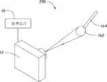
图1是本发明第一实施例三维光学感测系统的立体示意图。FIG. 1 is a three-dimensional schematic diagram of a three-dimensional optical sensing system according to a first embodiment of the present invention.
图2为利用图1中的三维光学感测系统进行光学感测的原理示意图。FIG. 2 is a schematic diagram of the principle of optical sensing using the 3D optical sensing system in FIG. 1 .
图3是本发明第二实施例三维光学感测系统的立体示意图。FIG. 3 is a three-dimensional schematic diagram of a 3D optical sensing system according to a second embodiment of the present invention.
图4是本发明第三实施例的游戏机的示意图。Fig. 4 is a schematic diagram of a game machine according to a third embodiment of the present invention.
具体实施方式Detailed ways
下面将结合附图对本发明作进一步详细说明。The present invention will be described in further detail below in conjunction with the accompanying drawings.
请参阅图1,本发明第一实施提供一种三维光学感测系统100,其包括一个光感测装置12,一个红外发光元件14、一个待感测元件16以及一个处理芯片18。Referring to FIG. 1 , the first embodiment of the present invention provides a 3D optical sensing system 100 , which includes a
该光感测装置12具有进光口122,外界光线从该进光口122进入该光感测装置12内。该光感测装置12为一红外光感测装置,用于对进入其内的红外光进行感测。本实施例中,该光感测装置12为二维感测装置,其内包括一个由二维行列式排列的多个光感测单元形成的感测芯片(图未示)。The
该红外发光元件14与该光感测装置12相邻设置,且该红外发光元件14的出光方向与该光感测装置12的进光口122位于同一侧。该红外发光元件14可以为红外发光二极管。The infrared
该待感测元件16用于将红外发光元件14发出的光反射至该光感测装置12。该待感测元件16包括一个球形反射体162及一个与该反射体162连接固定的握持部164。该球形反射体162的球形外表面为粗糙面,以将光线散射,当红外发光元件14发出的光照射至球形反射体162表面时,使球形反射体162轮廓线附近也有光线被反射至该光感测装置12。如此,可使反射体162反射之光线进入该光感测装置12后所形成的图像对应球形反射体162的圆形轮廓。The
该握持部164为柱状等适于操作者握持的形状,且优选其表面为粗糙表面,以便于手的握持。该握持部164的材料为吸光材料,以防止其反射来自红外发光元件14的光线至该光感测装置12,以保证光感测的精确性。优选地,该握持部164的径向最大宽度远远小于该反射体162的直径,如握持部164的径向最大宽度可以为反射体162直径的三分之一至十分之一。需要说明的是,所述径向最大宽度表示,以与握持部164径向方向平行的任意直线去截该握持部164,被握持部164所截得到的最长线段的长度。The
该处理芯片18与该光感测装置12电连接。定义一个三维坐标系X-Y-Z,其中X轴方向及Y轴方向分别相互垂直且分别平行于上述光感测装置12的感测单元排列方向的行和列,Z轴垂直于X轴及Y轴。当待测元件16位于与光感测装置12相对的某处时,待测元件16与光感测装置12的连线与Z轴具有一夹角,该处理芯片18的作用之一为根据球形反射体162在光感测装置12的感测芯片内成像的位置相对于该感测芯片的中心的偏移量,计算上述连线在X-Z平面的投影与Z轴的夹角及上述连线在Y-Z平面内的投影与Z轴的夹角。The
另外,处理芯片18内存储有球形反射体162成像尺寸信息和球形反射体162与光感测装置12的距离的对应关系信息,处理芯片18的另一作用为根据球形反射体162在该感测芯片内成像的尺寸及上述成像尺寸与距离的对应关系,得到球形反射体162与光感测装置12的距离。根据上述球形反射体162在光感测装置12的感测芯片内成像的位置与感测芯片的中心相对偏移量以及球形反射体162与光感测装置12的距离,可以计算得出待感测元件16的球形反射体162与光感测装置12的空间相对位置关系。In addition, the
请参阅图1和图2,利用该三维光学感测系统100进行三维位置感测的过程如下:Referring to FIG. 1 and FIG. 2, the process of using the 3D optical sensing system 100 for 3D position sensing is as follows:
首先,将球形反射体162置于与光感测装置12的进光口122相对的位置,本实施例中,光感测装置12的感测芯片的解析度为640×480,即光感测装置12包括640×480个光感测单元,每个光感测单元的宽度为2微米(micron,μm)。如图2所示,光感测装置12的光轴为0,光感测装置12的视场角度θ为53.13°。First, the
其次,如图2所示,红外发光元件14发出红外光,球形反射体162反射该红外光线至该光感测装置12,由该光感测装置12的感测芯片进行感测。由于球形从各个方向观察,其轮廓均为大小相同的圆形,因此,由该球形反射体162反射的红外光线进入光感测装置12后,在该光感测装置12的感测芯片内形成一与该球形反射体162的轮廓线所限定的圆形区域相对应的感测区域,因为光感测装置12的进光口122与感测芯片的距离为毫米量级,当球形反射体162与光感测装置12的距离远远进光口122与感测芯片的距离,如大于1米时,该球形反射体162反射的光线被光感测装置12的感测芯片所感测所形成的感测区域的形状均可等价于圆形。处理芯片18根据该圆形感测区域在该感测芯片上的位置,该位置即该圆形感测区域的中心位置相对于该感测芯片的中心的偏移量,计算得出该圆形感测区域的中心和球形反射体162中心连线在X-Z平面内的投影L与Z轴的夹角θ1,以及该圆形感测区域的中心和球形反射体162中心连线在Y-Z平面内的投影与Z轴的夹角(图未示)。上述夹角可根据该圆形感测区域的中心相对于该感测芯片的中心的偏移量来确定,因为上述夹角与上述偏移量具有一一对应关系。Next, as shown in FIG. 2 , the infrared
然后,处理芯片18根据其内存储的球形反射体162成像尺寸信息和球形反射体162与光感测装置12的距离的对应关系信息,得出球形反射体162与光感测装置12之间的距离。本实施例中,以反射体162成像所占光感测单元数对应于反射体162的尺寸信息,反射体162成像所占光感测单元数与该光感测装置12和反射体162之间的距离的对应关系具有一定精度。例如:当反射体162的直径为3厘米(centimeter,cm),反射体162与光感测装置12之间的距离为3米(meter,m)时,对应光感测装置12的光感测单元数为8个,距离为2.7m时,对应光感测单元数为9个,如此,则本实施例中,当球形反射体162的直径为3cm时,反射体与光感测装置12之间的距离约3m处的感测精度约为0.3米,反射体与光感测装置12之间的距离越近,球形反射体162的直径越大,感测精度越高。Then, the
最后,结合上述圆形感测区域的中心和球形反射体162中心连线分别在X-Z平面和Y-Z平面的投影与Z轴的夹角,得出该球形反射体162与该光感测装置12的之间的相对位置关系。如此,则本实施例的三维光学感测系统100可在一定精度范围内感测球形反射体162在三维空间内的运动。Finally, in combination with the center of the above-mentioned circular sensing area and the center line of the
请参阅图3,本发明第二实施例提供一种三维光学感测系统200。本实施例的三维光学感测系统200与第一实施例的三维光学感测系统100相类似,不同之处在于,本实施例采用一球形发光元件262取代第一实施例的球形反射体162,省略了第一实施例的红外发光元件14。该球形发光元件262用于发出红外光至光感测装置12,并在光感测装置12的感测芯片上形成与球形发光元件262的轮廓所限定的圆形相对应的圆形感测区域。本实施例的三维光学感测系统200进行三维位置感测的原理与第一实施例的感测原理相类似,这里不再赘述。Please refer to FIG. 3 , the second embodiment of the present invention provides a 3D
请参阅图4,本发明第三实施例提供一种游戏机300。该游戏机300包括一个如第一实施例所述的三维光学感测系统100、一游戏机主机32及一显示屏幕34。该游戏机主机32通过数据线36与该三维光学感测系统100的处理芯片18电连接。当挥动该三维光学感测系统100的待感测元件16时,光感测装置感测到待感测元件16在三维空间内发生的位置变化,如设定不同的位置变化与游戏机主机32发出的各种指令相对应,则可实现对游戏机300的操作控制。如对显示屏幕34所显示的游戏场景中的人物或物体的动作进行操作控制。可以理解,该三维光学感测系统100也可以为第二实施例的三维光学感测系统200所取代。Referring to FIG. 4 , the third embodiment of the present invention provides a
可以理解,该游戏机主机32也可以与显示屏幕34制作为一体。另外,另外,该处理芯片18也可以安装于游戏机主体32内,并不限于本实施例。It can be understood that the
另外,本领域技术人员还可以在本发明精神内做其它变化,当然,这些依据本发明精神所做的变化,都应包含在本发明所要求保护的范围之内。In addition, those skilled in the art can also make other changes within the spirit of the present invention. Of course, these changes made according to the spirit of the present invention should be included within the scope of protection claimed by the present invention.
Claims (9)
Translated fromChinesePriority Applications (2)
| Application Number | Priority Date | Filing Date | Title |
|---|---|---|---|
| CN2009103073963ACN102022979A (en) | 2009-09-21 | 2009-09-21 | Three-dimensional optical sensing system |
| US12/698,222US8657682B2 (en) | 2009-09-21 | 2010-02-02 | Motion sensing controller and game apparatus having same |
Applications Claiming Priority (1)
| Application Number | Priority Date | Filing Date | Title |
|---|---|---|---|
| CN2009103073963ACN102022979A (en) | 2009-09-21 | 2009-09-21 | Three-dimensional optical sensing system |
Publications (1)
| Publication Number | Publication Date |
|---|---|
| CN102022979Atrue CN102022979A (en) | 2011-04-20 |
Family
ID=43756161
Family Applications (1)
| Application Number | Title | Priority Date | Filing Date |
|---|---|---|---|
| CN2009103073963APendingCN102022979A (en) | 2009-09-21 | 2009-09-21 | Three-dimensional optical sensing system |
Country Status (2)
| Country | Link |
|---|---|
| US (1) | US8657682B2 (en) |
| CN (1) | CN102022979A (en) |
Cited By (1)
| Publication number | Priority date | Publication date | Assignee | Title |
|---|---|---|---|---|
| CN109141298A (en)* | 2018-09-05 | 2019-01-04 | 广州达欧技术检测有限公司 | A kind of ball-type piece surface curve detection system |
Families Citing this family (4)
| Publication number | Priority date | Publication date | Assignee | Title |
|---|---|---|---|---|
| US8310380B2 (en)* | 2010-03-02 | 2012-11-13 | Invensense Inc. | Selectable communication interface configurations for motion sensing device |
| KR200471938Y1 (en) | 2011-07-09 | 2014-03-27 | 김재황 | Light switch circuit for arcade game |
| US9814982B2 (en) | 2015-02-25 | 2017-11-14 | Globalfoundries Inc. | Mitigating collisions in a physical space during gaming |
| US10814222B2 (en) | 2018-09-21 | 2020-10-27 | Logitech Europe S.A. | Gaming controller with adaptable input configurations |
Citations (7)
| Publication number | Priority date | Publication date | Assignee | Title |
|---|---|---|---|---|
| EP0766810B1 (en)* | 1994-06-22 | 2000-02-23 | Leica Geosystems AG | Optical device for determining the position of a reflective graticule |
| US20050009605A1 (en)* | 2003-07-11 | 2005-01-13 | Rosenberg Steven T. | Image-based control of video games |
| CN1856804A (en)* | 2003-09-26 | 2006-11-01 | 微一埃普西龙测量技术有限两合公司 | Method and device for contactless optical determination of the 3-D position of an object |
| WO2009075330A1 (en)* | 2007-12-11 | 2009-06-18 | Omron Corporation | Measuring method, inspecting method, measuring apparatus and inspecting apparatus |
| CN101464132A (en)* | 2008-12-31 | 2009-06-24 | 北京中星微电子有限公司 | Position confirming method and apparatus |
| CN101496033A (en)* | 2006-03-14 | 2009-07-29 | 普莱姆森斯有限公司 | Depth-varying light fields for three dimensional sensing |
| WO2009113484A1 (en)* | 2008-03-11 | 2009-09-17 | 株式会社ニコン | Reference sphere detecting device, reference sphere position detecting device, and three-dimensional coordinate measuring device |
Family Cites Families (10)
| Publication number | Priority date | Publication date | Assignee | Title |
|---|---|---|---|---|
| US4736640A (en)* | 1986-08-14 | 1988-04-12 | Hooks Mark M | Compact six-degree-of-freedom motion detecting apparatus and associated methods |
| US5741182A (en)* | 1994-06-17 | 1998-04-21 | Sports Sciences, Inc. | Sensing spatial movement |
| US6162123A (en)* | 1997-11-25 | 2000-12-19 | Woolston; Thomas G. | Interactive electronic sword game |
| US7445550B2 (en)* | 2000-02-22 | 2008-11-04 | Creative Kingdoms, Llc | Magical wand and interactive play experience |
| US9474968B2 (en)* | 2002-07-27 | 2016-10-25 | Sony Interactive Entertainment America Llc | Method and system for applying gearing effects to visual tracking |
| US8323106B2 (en)* | 2008-05-30 | 2012-12-04 | Sony Computer Entertainment America Llc | Determination of controller three-dimensional location using image analysis and ultrasonic communication |
| US8179366B2 (en)* | 2004-12-06 | 2012-05-15 | Naturalpoint, Inc. | Systems and methods for using a movable object to control a computer |
| TWI395603B (en)* | 2006-04-26 | 2013-05-11 | Pixart Imaging Inc | Interactive game apparatus and game controller using in the same |
| US20090017910A1 (en)* | 2007-06-22 | 2009-01-15 | Broadcom Corporation | Position and motion tracking of an object |
| US8221229B2 (en)* | 2008-10-27 | 2012-07-17 | Sony Computer Entertainment Inc. | Spherical ended controller with configurable modes |
- 2009
- 2009-09-21CNCN2009103073963Apatent/CN102022979A/enactivePending
- 2010
- 2010-02-02USUS12/698,222patent/US8657682B2/ennot_activeExpired - Fee Related
Patent Citations (7)
| Publication number | Priority date | Publication date | Assignee | Title |
|---|---|---|---|---|
| EP0766810B1 (en)* | 1994-06-22 | 2000-02-23 | Leica Geosystems AG | Optical device for determining the position of a reflective graticule |
| US20050009605A1 (en)* | 2003-07-11 | 2005-01-13 | Rosenberg Steven T. | Image-based control of video games |
| CN1856804A (en)* | 2003-09-26 | 2006-11-01 | 微一埃普西龙测量技术有限两合公司 | Method and device for contactless optical determination of the 3-D position of an object |
| CN101496033A (en)* | 2006-03-14 | 2009-07-29 | 普莱姆森斯有限公司 | Depth-varying light fields for three dimensional sensing |
| WO2009075330A1 (en)* | 2007-12-11 | 2009-06-18 | Omron Corporation | Measuring method, inspecting method, measuring apparatus and inspecting apparatus |
| WO2009113484A1 (en)* | 2008-03-11 | 2009-09-17 | 株式会社ニコン | Reference sphere detecting device, reference sphere position detecting device, and three-dimensional coordinate measuring device |
| CN101464132A (en)* | 2008-12-31 | 2009-06-24 | 北京中星微电子有限公司 | Position confirming method and apparatus |
Cited By (1)
| Publication number | Priority date | Publication date | Assignee | Title |
|---|---|---|---|---|
| CN109141298A (en)* | 2018-09-05 | 2019-01-04 | 广州达欧技术检测有限公司 | A kind of ball-type piece surface curve detection system |
Also Published As
| Publication number | Publication date |
|---|---|
| US20110068937A1 (en) | 2011-03-24 |
| US8657682B2 (en) | 2014-02-25 |
Similar Documents
| Publication | Publication Date | Title |
|---|---|---|
| US6897854B2 (en) | Electronic pen input device and coordinate detecting method therefor | |
| CN101598299B (en) | Light source module and game device using same | |
| JP6096222B2 (en) | Device for entering information into a data processing system | |
| CN111856073B (en) | Particle sensor based on beam-splitting self-mixing interferometry sensor | |
| JP3975892B2 (en) | Position measurement system | |
| US20060227210A1 (en) | Three-dimensional coordinate measuring device | |
| JP2004170412A (en) | Method and system for calibrating measuring system | |
| JP2020518820A (en) | Triangulation scanner that projects a flat shape and uncoded spot | |
| US20140104169A1 (en) | Method for Determining the Relative Position of an Object in an Area, and Optical Input System | |
| US20090122008A1 (en) | Probe With A Virtual Marker | |
| US9212889B2 (en) | Apparatus for pointing spatial coordinates, comprising a movable hand-held probe and a portable base unit, and a related method | |
| CN102855030B (en) | Instruction parts, optical position detector and the display system of input function | |
| EP0366112A2 (en) | Optical coordinate input apparatus and position indicator therefor | |
| CN101952793A (en) | Touch screen adopting an optical module system using linear infrared emitters | |
| US7941913B2 (en) | Component placement unit as well as a component placement device comprising such a component placement unit | |
| CN102022979A (en) | Three-dimensional optical sensing system | |
| CN101236468B (en) | Mouse indication system, mouse indicating equipment and mouse indication method | |
| US8854338B2 (en) | Display apparatus and method of controlling display apparatus | |
| US9465486B2 (en) | Portable interactive whiteboard module | |
| TWI459243B (en) | Three dimensional optical sensing system and game player | |
| TWI552026B (en) | Hand-held pointing device | |
| CN102063228B (en) | Optical sensing system and touch screen applying same | |
| JP2004038528A (en) | Optical coordinate detecting device | |
| JP2009199247A (en) | Object recognition apparatus, indicating device and program | |
| JPH08320207A (en) | Coordinate input apparatus and light emitting body for the apparatus |
Legal Events
| Date | Code | Title | Description |
|---|---|---|---|
| C06 | Publication | ||
| PB01 | Publication | ||
| C10 | Entry into substantive examination | ||
| SE01 | Entry into force of request for substantive examination | ||
| C12 | Rejection of a patent application after its publication | ||
| RJ01 | Rejection of invention patent application after publication | Application publication date:20110420 |