CN102016382A - Multi-axis metamorphic actuator and drive system and method - Google Patents
Multi-axis metamorphic actuator and drive system and methodDownload PDFInfo
- Publication number
- CN102016382A CN102016382ACN2008801287410ACN200880128741ACN102016382ACN 102016382 ACN102016382 ACN 102016382ACN 2008801287410 ACN2008801287410 ACN 2008801287410ACN 200880128741 ACN200880128741 ACN 200880128741ACN 102016382 ACN102016382 ACN 102016382A
- Authority
- CN
- China
- Prior art keywords
- fluid
- support structure
- containers
- container
- volume
- Prior art date
- Legal status (The legal status is an assumption and is not a legal conclusion. Google has not performed a legal analysis and makes no representation as to the accuracy of the status listed.)
- Granted
Links
- 238000000034methodMethods0.000titleclaimsabstractdescription31
- 239000012530fluidSubstances0.000claimsabstractdescription232
- 230000033001locomotionEffects0.000claimsdescription21
- 230000008859changeEffects0.000claimsdescription14
- 230000007246mechanismEffects0.000claimsdescription13
- 230000008878couplingEffects0.000claimsdescription11
- 238000010168coupling processMethods0.000claimsdescription11
- 238000005859coupling reactionMethods0.000claimsdescription11
- 238000010438heat treatmentMethods0.000claimsdescription10
- 239000007787solidSubstances0.000claimsdescription10
- 238000004891communicationMethods0.000claimsdescription5
- 238000010276constructionMethods0.000claimsdescription5
- 239000007788liquidSubstances0.000claimsdescription4
- 230000005670electromagnetic radiationEffects0.000claimsdescription3
- 239000007943implantSubstances0.000claimsdescription2
- 238000003331infrared imagingMethods0.000claimsdescription2
- 230000004044responseEffects0.000claimsdescription2
- XLYOFNOQVPJJNP-UHFFFAOYSA-NwaterSubstancesOXLYOFNOQVPJJNP-UHFFFAOYSA-N0.000claimsdescription2
- 238000006243chemical reactionMethods0.000claims1
- 230000006837decompressionEffects0.000claims1
- 238000003745diagnosisMethods0.000claims1
- 238000006073displacement reactionMethods0.000claims1
- 238000010586diagramMethods0.000description7
- 238000012423maintenanceMethods0.000description7
- 239000000463materialSubstances0.000description7
- VNWKTOKETHGBQD-UHFFFAOYSA-NmethaneChemical compoundCVNWKTOKETHGBQD-UHFFFAOYSA-N0.000description6
- 230000006870functionEffects0.000description5
- 238000009434installationMethods0.000description5
- 238000003491arrayMethods0.000description4
- 239000004744fabricSubstances0.000description4
- 238000004519manufacturing processMethods0.000description4
- 239000002184metalSubstances0.000description4
- 230000008569processEffects0.000description4
- 230000005540biological transmissionEffects0.000description3
- 238000009826distributionMethods0.000description3
- 238000005516engineering processMethods0.000description3
- 239000007789gasSubstances0.000description3
- 239000003345natural gasSubstances0.000description3
- 238000003825pressingMethods0.000description3
- 230000005855radiationEffects0.000description3
- 230000008439repair processEffects0.000description3
- 238000001356surgical procedureMethods0.000description3
- 230000002159abnormal effectEffects0.000description2
- 230000006835compressionEffects0.000description2
- 238000007906compressionMethods0.000description2
- 230000009977dual effectEffects0.000description2
- 230000005611electricityEffects0.000description2
- 230000006355external stressEffects0.000description2
- 238000007689inspectionMethods0.000description2
- 238000002406microsurgeryMethods0.000description2
- 238000012545processingMethods0.000description2
- 230000035939shockEffects0.000description2
- 101100258233Caenorhabditis elegans sun-1 geneProteins0.000description1
- 229920000742CottonPolymers0.000description1
- 239000004677NylonSubstances0.000description1
- FAPWRFPIFSIZLT-UHFFFAOYSA-MSodium chlorideChemical compound[Na+].[Cl-]FAPWRFPIFSIZLT-UHFFFAOYSA-M0.000description1
- 229910000831SteelInorganic materials0.000description1
- 239000003570airSubstances0.000description1
- 238000004873anchoringMethods0.000description1
- 230000000712assemblyEffects0.000description1
- 238000000429assemblyMethods0.000description1
- 230000008901benefitEffects0.000description1
- 239000003034coal gasSubstances0.000description1
- 230000008602contractionEffects0.000description1
- 238000013461designMethods0.000description1
- 239000003814drugSubstances0.000description1
- 239000000428dustSubstances0.000description1
- 230000000694effectsEffects0.000description1
- 230000005684electric fieldEffects0.000description1
- 238000005485electric heatingMethods0.000description1
- 230000002349favourable effectEffects0.000description1
- 239000000499gelSubstances0.000description1
- 230000005484gravityEffects0.000description1
- 238000003306harvestingMethods0.000description1
- 230000036541healthEffects0.000description1
- 230000008407joint functionEffects0.000description1
- 239000000314lubricantSubstances0.000description1
- 230000010534mechanism of actionEffects0.000description1
- 238000002844meltingMethods0.000description1
- 230000008018meltingEffects0.000description1
- 239000012528membraneSubstances0.000description1
- 238000005065miningMethods0.000description1
- 239000005445natural materialSubstances0.000description1
- 230000007935neutral effectEffects0.000description1
- 229920001778nylonPolymers0.000description1
- 239000003921oilSubstances0.000description1
- 230000003287optical effectEffects0.000description1
- 239000012188paraffin waxSubstances0.000description1
- 230000000737periodic effectEffects0.000description1
- 238000010248power generationMethods0.000description1
- 230000009467reductionEffects0.000description1
- 239000005060rubberSubstances0.000description1
- 230000001568sexual effectEffects0.000description1
- 238000007493shaping processMethods0.000description1
- 238000004904shorteningMethods0.000description1
- 239000011780sodium chlorideSubstances0.000description1
- 230000003068static effectEffects0.000description1
- 239000010959steelSubstances0.000description1
- 238000003860storageMethods0.000description1
- 230000035882stressEffects0.000description1
- 239000000126substanceSubstances0.000description1
- 230000002459sustained effectEffects0.000description1
- 239000004753textileSubstances0.000description1
- 238000001931thermographyMethods0.000description1
- 230000005641tunnelingEffects0.000description1
- 229920002554vinyl polymerPolymers0.000description1
- 239000002759woven fabricSubstances0.000description1
Images


Classifications
- F—MECHANICAL ENGINEERING; LIGHTING; HEATING; WEAPONS; BLASTING
- F03—MACHINES OR ENGINES FOR LIQUIDS; WIND, SPRING, OR WEIGHT MOTORS; PRODUCING MECHANICAL POWER OR A REACTIVE PROPULSIVE THRUST, NOT OTHERWISE PROVIDED FOR
- F03G—SPRING, WEIGHT, INERTIA OR LIKE MOTORS; MECHANICAL-POWER PRODUCING DEVICES OR MECHANISMS, NOT OTHERWISE PROVIDED FOR OR USING ENERGY SOURCES NOT OTHERWISE PROVIDED FOR
- F03G7/00—Mechanical-power-producing mechanisms, not otherwise provided for or using energy sources not otherwise provided for
- F03G7/06—Mechanical-power-producing mechanisms, not otherwise provided for or using energy sources not otherwise provided for using expansion or contraction of bodies due to heating, cooling, moistening, drying or the like
- F03G7/061—Mechanical-power-producing mechanisms, not otherwise provided for or using energy sources not otherwise provided for using expansion or contraction of bodies due to heating, cooling, moistening, drying or the like characterised by the actuating element
- F03G7/06112—Mechanical-power-producing mechanisms, not otherwise provided for or using energy sources not otherwise provided for using expansion or contraction of bodies due to heating, cooling, moistening, drying or the like characterised by the actuating element using the thermal expansion or contraction of enclosed fluids
- F03G7/06113—Mechanical-power-producing mechanisms, not otherwise provided for or using energy sources not otherwise provided for using expansion or contraction of bodies due to heating, cooling, moistening, drying or the like characterised by the actuating element using the thermal expansion or contraction of enclosed fluids the fluids subjected to phase change
- F—MECHANICAL ENGINEERING; LIGHTING; HEATING; WEAPONS; BLASTING
- F03—MACHINES OR ENGINES FOR LIQUIDS; WIND, SPRING, OR WEIGHT MOTORS; PRODUCING MECHANICAL POWER OR A REACTIVE PROPULSIVE THRUST, NOT OTHERWISE PROVIDED FOR
- F03G—SPRING, WEIGHT, INERTIA OR LIKE MOTORS; MECHANICAL-POWER PRODUCING DEVICES OR MECHANISMS, NOT OTHERWISE PROVIDED FOR OR USING ENERGY SOURCES NOT OTHERWISE PROVIDED FOR
- F03G7/00—Mechanical-power-producing mechanisms, not otherwise provided for or using energy sources not otherwise provided for
- F03G7/06—Mechanical-power-producing mechanisms, not otherwise provided for or using energy sources not otherwise provided for using expansion or contraction of bodies due to heating, cooling, moistening, drying or the like
- F03G7/066—Actuator control or monitoring
- F03G7/0665—Actuator control or monitoring controlled displacement, e.g. by using a lens positioning actuator
- F—MECHANICAL ENGINEERING; LIGHTING; HEATING; WEAPONS; BLASTING
- F16—ENGINEERING ELEMENTS AND UNITS; GENERAL MEASURES FOR PRODUCING AND MAINTAINING EFFECTIVE FUNCTIONING OF MACHINES OR INSTALLATIONS; THERMAL INSULATION IN GENERAL
- F16M—FRAMES, CASINGS OR BEDS OF ENGINES, MACHINES OR APPARATUS, NOT SPECIFIC TO ENGINES, MACHINES OR APPARATUS PROVIDED FOR ELSEWHERE; STANDS; SUPPORTS
- F16M11/00—Stands or trestles as supports for apparatus or articles placed thereon ; Stands for scientific apparatus such as gravitational force meters
- F16M11/02—Heads
- F16M11/04—Means for attachment of apparatus; Means allowing adjustment of the apparatus relatively to the stand
- F16M11/06—Means for attachment of apparatus; Means allowing adjustment of the apparatus relatively to the stand allowing pivoting
- F16M11/12—Means for attachment of apparatus; Means allowing adjustment of the apparatus relatively to the stand allowing pivoting in more than one direction
- F16M11/125—Means for attachment of apparatus; Means allowing adjustment of the apparatus relatively to the stand allowing pivoting in more than one direction for tilting and rolling
- F—MECHANICAL ENGINEERING; LIGHTING; HEATING; WEAPONS; BLASTING
- F16—ENGINEERING ELEMENTS AND UNITS; GENERAL MEASURES FOR PRODUCING AND MAINTAINING EFFECTIVE FUNCTIONING OF MACHINES OR INSTALLATIONS; THERMAL INSULATION IN GENERAL
- F16M—FRAMES, CASINGS OR BEDS OF ENGINES, MACHINES OR APPARATUS, NOT SPECIFIC TO ENGINES, MACHINES OR APPARATUS PROVIDED FOR ELSEWHERE; STANDS; SUPPORTS
- F16M11/00—Stands or trestles as supports for apparatus or articles placed thereon ; Stands for scientific apparatus such as gravitational force meters
- F16M11/02—Heads
- F16M11/18—Heads with mechanism for moving the apparatus relatively to the stand
- F—MECHANICAL ENGINEERING; LIGHTING; HEATING; WEAPONS; BLASTING
- F24—HEATING; RANGES; VENTILATING
- F24S—SOLAR HEAT COLLECTORS; SOLAR HEAT SYSTEMS
- F24S30/00—Arrangements for moving or orienting solar heat collector modules
- F24S30/40—Arrangements for moving or orienting solar heat collector modules for rotary movement
- F24S30/48—Arrangements for moving or orienting solar heat collector modules for rotary movement with three or more rotation axes or with multiple degrees of freedom
- H—ELECTRICITY
- H02—GENERATION; CONVERSION OR DISTRIBUTION OF ELECTRIC POWER
- H02S—GENERATION OF ELECTRIC POWER BY CONVERSION OF INFRARED RADIATION, VISIBLE LIGHT OR ULTRAVIOLET LIGHT, e.g. USING PHOTOVOLTAIC [PV] MODULES
- H02S20/00—Supporting structures for PV modules
- H02S20/10—Supporting structures directly fixed to the ground
- H—ELECTRICITY
- H02—GENERATION; CONVERSION OR DISTRIBUTION OF ELECTRIC POWER
- H02S—GENERATION OF ELECTRIC POWER BY CONVERSION OF INFRARED RADIATION, VISIBLE LIGHT OR ULTRAVIOLET LIGHT, e.g. USING PHOTOVOLTAIC [PV] MODULES
- H02S20/00—Supporting structures for PV modules
- H02S20/30—Supporting structures being movable or adjustable, e.g. for angle adjustment
- H02S20/32—Supporting structures being movable or adjustable, e.g. for angle adjustment specially adapted for solar tracking
- F—MECHANICAL ENGINEERING; LIGHTING; HEATING; WEAPONS; BLASTING
- F16—ENGINEERING ELEMENTS AND UNITS; GENERAL MEASURES FOR PRODUCING AND MAINTAINING EFFECTIVE FUNCTIONING OF MACHINES OR INSTALLATIONS; THERMAL INSULATION IN GENERAL
- F16M—FRAMES, CASINGS OR BEDS OF ENGINES, MACHINES OR APPARATUS, NOT SPECIFIC TO ENGINES, MACHINES OR APPARATUS PROVIDED FOR ELSEWHERE; STANDS; SUPPORTS
- F16M2200/00—Details of stands or supports
- F16M2200/04—Balancing means
- F16M2200/041—Balancing means for balancing rotational movement of the head
- F—MECHANICAL ENGINEERING; LIGHTING; HEATING; WEAPONS; BLASTING
- F24—HEATING; RANGES; VENTILATING
- F24S—SOLAR HEAT COLLECTORS; SOLAR HEAT SYSTEMS
- F24S30/00—Arrangements for moving or orienting solar heat collector modules
- F24S2030/10—Special components
- F24S2030/11—Driving means
- F—MECHANICAL ENGINEERING; LIGHTING; HEATING; WEAPONS; BLASTING
- F24—HEATING; RANGES; VENTILATING
- F24S—SOLAR HEAT COLLECTORS; SOLAR HEAT SYSTEMS
- F24S30/00—Arrangements for moving or orienting solar heat collector modules
- F24S2030/10—Special components
- F24S2030/11—Driving means
- F24S2030/115—Linear actuators, e.g. pneumatic cylinders
- Y—GENERAL TAGGING OF NEW TECHNOLOGICAL DEVELOPMENTS; GENERAL TAGGING OF CROSS-SECTIONAL TECHNOLOGIES SPANNING OVER SEVERAL SECTIONS OF THE IPC; TECHNICAL SUBJECTS COVERED BY FORMER USPC CROSS-REFERENCE ART COLLECTIONS [XRACs] AND DIGESTS
- Y02—TECHNOLOGIES OR APPLICATIONS FOR MITIGATION OR ADAPTATION AGAINST CLIMATE CHANGE
- Y02E—REDUCTION OF GREENHOUSE GAS [GHG] EMISSIONS, RELATED TO ENERGY GENERATION, TRANSMISSION OR DISTRIBUTION
- Y02E10/00—Energy generation through renewable energy sources
- Y02E10/40—Solar thermal energy, e.g. solar towers
- Y02E10/46—Conversion of thermal power into mechanical power, e.g. Rankine, Stirling or solar thermal engines
- Y—GENERAL TAGGING OF NEW TECHNOLOGICAL DEVELOPMENTS; GENERAL TAGGING OF CROSS-SECTIONAL TECHNOLOGIES SPANNING OVER SEVERAL SECTIONS OF THE IPC; TECHNICAL SUBJECTS COVERED BY FORMER USPC CROSS-REFERENCE ART COLLECTIONS [XRACs] AND DIGESTS
- Y02—TECHNOLOGIES OR APPLICATIONS FOR MITIGATION OR ADAPTATION AGAINST CLIMATE CHANGE
- Y02E—REDUCTION OF GREENHOUSE GAS [GHG] EMISSIONS, RELATED TO ENERGY GENERATION, TRANSMISSION OR DISTRIBUTION
- Y02E10/00—Energy generation through renewable energy sources
- Y02E10/40—Solar thermal energy, e.g. solar towers
- Y02E10/47—Mountings or tracking
- Y—GENERAL TAGGING OF NEW TECHNOLOGICAL DEVELOPMENTS; GENERAL TAGGING OF CROSS-SECTIONAL TECHNOLOGIES SPANNING OVER SEVERAL SECTIONS OF THE IPC; TECHNICAL SUBJECTS COVERED BY FORMER USPC CROSS-REFERENCE ART COLLECTIONS [XRACs] AND DIGESTS
- Y02—TECHNOLOGIES OR APPLICATIONS FOR MITIGATION OR ADAPTATION AGAINST CLIMATE CHANGE
- Y02E—REDUCTION OF GREENHOUSE GAS [GHG] EMISSIONS, RELATED TO ENERGY GENERATION, TRANSMISSION OR DISTRIBUTION
- Y02E10/00—Energy generation through renewable energy sources
- Y02E10/50—Photovoltaic [PV] energy
Landscapes
- Engineering & Computer Science (AREA)
- General Engineering & Computer Science (AREA)
- Mechanical Engineering (AREA)
- Chemical & Material Sciences (AREA)
- Combustion & Propulsion (AREA)
- Life Sciences & Earth Sciences (AREA)
- Sustainable Development (AREA)
- Physics & Mathematics (AREA)
- Sustainable Energy (AREA)
- Thermal Sciences (AREA)
- Actuator (AREA)
- Fluid-Pressure Circuits (AREA)
Abstract
Translated fromChinese
Description
Translated fromChinese技术领域technical field
技术领域涉及用于沿两个或更多个轴支承和移动物体的系统和方法。作为对用于沿精确的或不精确的多轴方位移动、驱动、定位或者致动物体或负荷或工具(诸如用于定位定日镜、太阳能跟踪系统、电磁辐射天线以及其他大的或小的物体)的较老的技术、机构以及方法的完全代替,该用于沿两个或更多个轴支承和移动物体的系统可以应用于各种各样的领域中的任何一个。The technical field relates to systems and methods for supporting and moving objects along two or more axes. As a tool for moving, driving, positioning, or actuating objects or loads or tools in precise or imprecise multi-axis orientations, such as for positioning heliostats, solar tracking systems, electromagnetic radiation antennas, and other large or small Objects), the system for supporting and moving objects along two or more axes can be applied in any of a wide variety of fields.
背景技术Background technique
各种各样的致动器当前被用来在各种领域(诸如太阳能、天文学、人造卫星、雷达、热成象、建筑以及广告业)中沿方位、高度以及方位角的多个轴操作和定位物体。对于大型设备或重型设备应用,当前的致动器使用齿轮传动、行星齿轮、蜗杆传动、齿轮和小齿条、液压活塞、气动活塞、螺旋传动以及各种时钟机构机械,以围绕固定支架定位大且重的物体。由于它们依靠电机移动重且大的物体,所以当前的致动器需要大量精确制造的部件和相当大的电源。这些装置使用昂贵的软管和电缆线路传输电力。另外,当前的多轴致动器还使用在结构构件和致动器之间的多个重型连接器(heavy connection)以支承和定位重且大的物体。虽然可利用简化的致动器,但是它们不具有沿多轴定位重且大的物体的能力。例如,美国专利4560145公开了一种可以利用单个气囊沿一个轴举起或移动物体以迫使物体移动的气囊千斤顶。A wide variety of actuators are currently used to operate and operate along multiple axes of azimuth, altitude, and azimuth in various fields such as solar energy, astronomy, satellites, radar, thermal imaging, construction, and advertising. Locate objects. For large equipment or heavy equipment applications, current actuators use gear drives, planetary gears, worm drives, rack and pinion, hydraulic pistons, pneumatic pistons, screw drives, and various clockwork mechanisms to position large and heavy objects. Because they rely on electric motors to move heavy and large objects, current actuators require a large number of precisely manufactured parts and considerable power supplies. These units transmit power using expensive hose and cable lines. Additionally, current multi-axis actuators also use multiple heavy connections between the structural member and the actuator to support and position heavy and bulky objects. While simplified actuators are available, they do not have the ability to position heavy and large objects along multiple axes. For example, US Patent 4,560,145 discloses an air bag jack that can lift or move an object along one axis using a single air bag to force the object to move.
当前的多轴致动器的另一个缺点是由于它们的重量级的且精确的金属对金属的传动装置和结构,所以正常的金属疲劳,操作的磨损以及外应力(诸如灰尘、污染物、外物、润滑油问题),甚至较小的操作者误差和疏忽都会导致显著的与使用有关的损坏、颤动、空转以及随之发生的精确性和耐久性的降低。也被称为“时钟机构”致动器的这种致动器使检查、维护、修理以及更换精密加工的部件的高成本,以及随之发生的来自生产作业的停工期成为必然。该时钟机构致动器不提供顺畅的跟踪运动,而是提供为电动系统所共有的周期步进运动。Another disadvantage of current multi-axis actuators is that due to their heavyweight and precise metal-to-metal gearing and construction, normal metal fatigue, wear and tear from operation, and external stresses (such as dust, substances, lubricant problems), and even minor operator errors and oversights can result in significant use-related damage, chatter, lost motion, and consequent loss of accuracy and durability. Such actuators, also known as "clockwork" actuators, necessitate high costs for inspection, maintenance, repair, and replacement of precision machined components, with consequent downtime from production operations. The clockwork actuator does not provide a smooth tracking motion, but a periodic stepping motion common to motorized systems.
时钟机构致动器可以与沿多轴旋转的太阳能收集装置结合使用,以在全天和全年维持太阳能电池板和太阳能集热器或镜子的希望方位。这些装置被称为“定日镜”或“定位系统”。迄今,当前的定位系统复杂且昂贵。特别是当镜子和光伏板的尺寸增大至在单个跟踪器上超过100m2时,特别是在疾风条件下操纵和稳定板所需的复杂精确的齿轮传动和大功率马达已经显现为追求大规模太阳能发电中最大的单个成本障碍。这些时钟机构致动器是精密的并且在正常和反常运行条件下倾向于机械故障或机械损伤。当前定日镜技术的这些和其他限制是使通过太阳热能或集中的太阳能发电的成本降低到等于或低于来自煤和天然气燃烧发电厂的电的成本的主要障碍之一。Clockwork actuators can be used in conjunction with solar collectors rotating in multiple axes to maintain desired orientations of solar panels and solar collectors or mirrors throughout the day and year. These devices are known as "heliostats" or "positioning systems". To date, current positioning systems are complex and expensive. Especially as the size of mirrors and photovoltaic panels increases to over100m2 on a single tracker, the complex and precise gearing and high-power motors required to maneuver and stabilize the panels especially in high wind conditions have emerged as the pursuit of large-scale The largest single cost hurdle in solar power generation. These clockwork actuators are delicate and prone to mechanical failure or mechanical damage under normal and abnormal operating conditions. These and other limitations of current heliostat technology are one of the major obstacles to reducing the cost of electricity from solar thermal or concentrated solar power to equal or below the cost of electricity from coal and natural gas fired power plants.
当前定日镜技术的其他典型实例包括美国专利3070643,该美国专利公开了一种用于通过利用具有单个驱动马达和电动离合器的复杂的传动装置系统以允许选择性的双轴驱动来感觉太阳的位置而将太阳能电池连续地直接指向太阳的闭环伺服系统。美国专利3998206和3996917中公开的另一个系统采用单独的驱动马达来获得双轴运动。使用马达驱动和齿轮减速显著地增加了太阳跟踪装置的初始安装和维护成本。另外,驱动大功率马达所需的动力在太阳能发电厂运转时导致附加的动力消耗。使用齿轮和马达驱动是如作为实例的美国专利6440019中所公开的当前致动器的特征。Other typical examples of current heliostat technology include U.S. Patent 3,070,643, which discloses a system for sensing the sun by utilizing a complex transmission system with a single drive motor and electric clutch to allow selective dual shaft drive. position to continuously point the solar cells directly at the sun's closed-loop servo system. Another system disclosed in US Pat. Nos. 3,998,206 and 3,996,917 uses separate drive motors to achieve dual axis motion. The use of motor drives and gear reductions adds significantly to the initial installation and maintenance costs of the sun tracking device. In addition, the power required to drive a high-power motor results in additional power consumption when the solar power plant is in operation. The use of gears and motor drive is a feature of current actuators as disclosed in US Patent 6,440,019 by way of example.
当前的定日镜技术的另一个缺点是其在大多数情况下对外部动力源的依赖。当前致动器需要供应电力或水力以确定在安装时产生附加动力消耗的应用的方向,并且也需要使用电缆或软管的复杂且昂贵的电或水力分配系统来用于他们的运转。由于它们的特性,定日镜阵列常常覆盖许多平方公里,并且因而,在大的安装范围内,通过电缆将外电源供应给数千个定日镜的阵列增加了主要的资本费用和维护费用。当前的致动器未能实现具有最小电源要求的提供多轴太阳跟踪的低成本装置。Another disadvantage of current heliostat technology is its dependence in most cases on an external power source. Current actuators require a supply of electrical or hydraulic power to orient the application creating additional power consumption when installed, and also require complex and expensive electrical or hydraulic distribution systems using cables or hoses for their operation. By their nature, heliostat arrays often cover many square kilometers, and thus, over large installations, supplying external power via cables to arrays of thousands of heliostats adds major capital and maintenance costs. Current actuators fail to enable low-cost devices that provide multi-axis sun tracking with minimal power requirements.
依靠时钟机构齿轮传动的当前定日镜的另一个缺点是用于致动的齿轮传动系统也用作多轴铰链或轴承,并且因而可以将其力施加在单个点处和非常小的范围内。因此,时钟机构齿轮传动通过非常弱的杠杆作用施加力来进行方向控制。Another disadvantage of current heliostats that rely on clockwork gearing is that the gearing system used for actuation also acts as a multi-axis hinge or bearing, and thus can apply its force at a single point and over a very small range. Thus, clockwork gearing exerts force through very weak leverage for directional control.
此外,时钟机构齿轮传动不适合于在不均匀负荷或剪力下操作。由定日镜系统产生的动量例如将在齿轮传动上产生剪力。例如由风或其他外部因素施加于应用结构的边缘或侧面的任何剪力或不均匀负荷造成具有非常长的力矩臂的动态荷载。剪力在齿轮传动之上施加巨大的扭力,使其难以操作。Additionally, clockwork gear drives are not suitable for operation under uneven loads or shear forces. Momentum generated by the heliostat system, for example, will generate shear forces on the gear drive. Dynamic loads with very long moment arms are caused by any shear or uneven loads applied to the edges or sides of the application structure eg by wind or other external factors. Shear forces put enormous torque on top of the gear drive, making it difficult to maneuver.
当前的致动器系统的另一个缺点是维护成本高。因为齿轮传动用作用于应用至桅杆的附加装置的铰链或支承和单个点,所以维修或更换齿轮传动的部件通常需要折断桅杆并且移除整个应用表面。因此,需要一种改进的、有成本和能量效益的供小到大规模应用之用的多轴致动器。Another disadvantage of current actuator systems is high maintenance costs. Because the gear transmission acts as a hinge or support and a single point for attachments applied to the mast, repairing or replacing components of the gear transmission often requires snapping off the mast and removing the entire application surface. Accordingly, there is a need for an improved, cost- and energy-efficient multi-axis actuator for small to large scale applications.
发明内容Contents of the invention
用于沿两个或更多个轴移动物体的系统的实施方式包括流体和三个或更多个流体容器。该三个或更多个流体容器中的每一个均与所述物体直接或间接地接触。在所述三个或更多个流体容器中的至少一个中放置有一定量的流体。所述系统还包括流体移动器,该流体移动器可操作地与所述三个或更多个流体容器相连,用于将所述流体移入该三个或更多个容器内。所述系统还包括流体体积控制器,该流体体积控制器用于控制所述三个或更多个容器中的所述流体的体积。所述物体可以被支承在一个或更多个枢转点处。通过改变所述三个或更多个容器中的所述流体的体积来移动所述物体。An embodiment of a system for moving an object along two or more axes includes a fluid and three or more fluid containers. Each of the three or more fluid containers is in direct or indirect contact with the object. A quantity of fluid is placed in at least one of the three or more fluid containers. The system also includes a fluid mover operatively connected to the three or more fluid containers for moving the fluid into the three or more containers. The system also includes a fluid volume controller for controlling the volume of the fluid in the three or more containers. The object may be supported at one or more pivot points. The object is moved by changing the volume of the fluid in the three or more containers.
用于沿一个轴移动物体的系统的实施方式包括两个或更多个流体容器,该两个或更多个流体容器中的每一个均与所述物体直接或间接地物理接触。在所述两个或更多个流体容器中放置有一定量的流体。所述系统还包括:流体移动器,该流体移动器与所述一个或更多个流体容器相连接以将所述流体移入该一个或更多个容器内;和流体体积控制器,该流体体积控制器用于控制所述一个或更多个容器中的所述流体的体积。通过改变所述两个或更多个容器中的所述流体的体积来移动所述物体。Embodiments of the system for moving an object along an axis include two or more fluid containers, each of the two or more fluid containers is in direct or indirect physical contact with the object. A quantity of fluid is placed in the two or more fluid containers. The system also includes: a fluid mover coupled to the one or more fluid containers to move the fluid into the one or more containers; and a fluid volume controller, the fluid volume A controller is used to control the volume of said fluid in said one or more containers. The object is moved by changing the volume of the fluid in the two or more containers.
用于利用加压流体沿两维或更多维移动物体的方法包括:提供枢转点;利用加压流体在至少三个或更多个位置上将压力施加在所述物体上或者支持该物体;以及通过改变所述加压流体的体积来改变施加在一个位置处的所述压力。压力的变化移动所述物体。A method for moving an object in two or more dimensions using a pressurized fluid comprising: providing a pivot point; applying pressure to or supporting the object in at least three or more locations with a pressurized fluid and changing said pressure applied at a location by changing the volume of said pressurized fluid. The change in pressure moves the object.
用于利用加压流体沿两维或更多维移动物体的方法包括:提供流体容器;提供枢转点;提供导向系统,该导向先生发送用于位置变化的需求信号;提供控制系统,该控制系统接收来自所述导向系统的数据信号,解释所述数据信号,并将所述数据信号转换成压力变化或者流体体积变化。所述控制系统致动一个或更多个泵或者压缩机以改变所述一个或更多个流体容器中的所述加压流体的体积。所述加压流体的体积变化移动所述物体。A method for moving an object in two or more dimensions using a pressurized fluid includes: providing a fluid container; providing a pivot point; providing a guide system that sends a demand signal for a change in position; providing a control system that controls A system receives data signals from the pilot system, interprets the data signals, and converts the data signals into pressure changes or fluid volume changes. The control system actuates one or more pumps or compressors to vary the volume of the pressurized fluid in the one or more fluid containers. The change in volume of the pressurized fluid moves the object.
附图说明Description of drawings
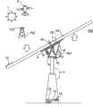
图1示出用于大型定日镜的用于沿两个或更多个轴移动物体的示例性系统的实施方式的侧视图;Figure 1 shows a side view of an embodiment of an exemplary system for moving an object along two or more axes for a large heliostat;
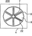
图2示出用于沿两个或更多个轴移动物体的系统的实施方式的截面俯视图;Figure 2 shows a cross-sectional top view of an embodiment of a system for moving an object along two or more axes;
图3示出图2的示例性系统的实施方式的等距侧视图,示出了构造为环状圈的、处于不同膨胀状态的流体容器的细节;Figure 3 illustrates an isometric side view of an embodiment of the exemplary system of Figure 2 showing details of a fluid container configured as an annular ring in various states of expansion;
图4示出具有凹入支点的用于沿两个或更多个轴移动物体的系统的侧视图;Figure 4 shows a side view of a system for moving an object along two or more axes with a concave fulcrum;
图5示出作为二维致动器的具有两个流体容器的用于沿两个或更多个轴移动物体的系统的实施方式的侧视图;Figure 5 shows a side view of an embodiment of a system for moving an object along two or more axes with two fluid containers as a two-dimensional actuator;
图6示出用于沿两个或更多个轴移动物体的系统的侧视图,其中可膨胀的流体容器处于压缩状态;Figure 6 shows a side view of a system for moving an object along two or more axes, wherein the expandable fluid container is in a compressed state;
图7示出用于沿两个或更多个轴移动物体的系统的侧视图,其中流体容器完全膨胀;Figure 7 shows a side view of a system for moving an object along two or more axes with the fluid container fully expanded;
图8示出包括作为一个系统工作的系统的多个实施方式的用于沿两个或更多个轴移动物体的系统的侧视图;Figure 8 shows a side view of a system for moving an object along two or more axes, including embodiments of the system operating as one system;
图9示出具有倒置的上支承结构的用于沿两个或更多个轴移动物体的系统的侧视图;Figure 9 shows a side view of a system for moving an object along two or more axes with an inverted upper support structure;
图10a和10b表示用于使每个流体容器加压和减压的空气或流体管的歧管的示意图;Figures 10a and 10b represent a schematic view of a manifold of air or fluid tubes for pressurizing and depressurizing each fluid container;
图11示出用于沿两个或更多个轴移动物体的系统的控制系统的示意图;Figure 11 shows a schematic diagram of a control system for a system for moving an object along two or more axes;
图12示出用于沿两个或更多个轴移动物体的系统的板上电源的示意图;Figure 12 shows a schematic diagram of an on-board power supply for a system for moving an object along two or more axes;
图13a示出为跟踪通信卫星接收机天线而配置的用于沿两个或更多个轴移动物体的系统的立体图;Figure 13a shows a perspective view of a system for moving an object along two or more axes configured for tracking a communication satellite receiver antenna;
图13b示出在需要机械手或致动器的应用中用在太空交通工具或空间站上的用于沿两个或更多个轴移动物体的系统的立体图;Figure 13b shows a perspective view of a system for moving objects along two or more axes for use on a space vehicle or space station in applications requiring manipulators or actuators;
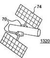
图13c示出用于旋转与接收器对准的天线的用于沿两个或更多个轴移动物体的系统的立体图;Figure 13c shows a perspective view of a system for moving an object along two or more axes for rotating an antenna aligned with a receiver;
图13d示出作为太空中的行星上的定日镜而配置的用于沿两个或更多个轴移动物体的系统的立体图;Figure 13d shows a perspective view of a system for moving an object along two or more axes configured as a heliostat on a planet in space;
图14a示出具体化为温室照明器的用于沿两个或更多个轴移动物体的系统的立体图;Figure 14a shows a perspective view of a system for moving an object along two or more axes embodied as a greenhouse luminaire;
图14b示出具体化为用于居住或商业建筑或者用于照明其他阴暗的公共区域的照明或供暖系统的用于沿两个或更多个轴移动物体的系统的立体图;Figure 14b shows a perspective view of a system for moving objects along two or more axes embodied as a lighting or heating system for residential or commercial buildings or for lighting other dark public areas;
图15a示出实施为医疗机器人致动器的用于沿两个或更多个轴移动物体的系统的立体图;Figure 15a shows a perspective view of a system for moving an object along two or more axes implemented as a medical robotic actuator;
图15b示出实施为用于失去的肢的假肢的用于沿两个或更多个轴移动物体的系统的立体图;Figure 15b shows a perspective view of a system for moving an object along two or more axes implemented as a prosthesis for a lost limb;
图15c示出实施为用于通过腹腔镜进行血管腔内手术或显微手术的显微手术操纵器的用于沿两个或更多个轴移动物体的系统的立体图;Figure 15c shows a perspective view of a system for moving an object along two or more axes implemented as a microsurgical manipulator for laparoscopically performing endovascular surgery or microsurgery;
图15d示出被采用以定位用于医疗的辐射源的用于沿两个或更多个轴移动物体的系统的立体图;以及Figure 15d shows a perspective view of a system for moving an object along two or more axes employed to position a radiation source for medical treatment; and
图16是示出用于沿两个或更多个轴移动物体的方法的流程图。Figure 16 is a flowchart illustrating a method for moving an object along two or more axes.
具体实施方式Detailed ways
在详细描述用于沿两个或更多个轴移动物体的系统的一个或更多个实施方式之前,本领域技术人员应理解,用于沿两个或更多个轴移动物体的系统在其应用中不限于下列详述中提出的或在附图中所示的结构、部件的布置以及步骤的排列的细节。用于沿两个或更多个轴移动物体的系统能够采用其他实施方式并且能够以各种方式实践或实施。而且,应当理解,本文使用的措词和术语是为了描述并且不应被认为是限制。Before describing in detail one or more embodiments of a system for moving an object along two or more axes, those skilled in the art should understand that a system for moving an object along two or more Applications are not limited to the details of construction, the arrangement of parts, and the arrangement of steps set forth in the following detailed description or shown in the drawings. A system for moving an object along two or more axes is capable of other embodiments and of being practiced or carried out in various ways. Also, it is to be understood that the phraseology and terminology used herein are for the purpose of description and should not be regarded as limiting.
用于沿两个或更多个轴移动物体的系统是新型的多轴致动器驱动机构和系统,该机构和系统可以在需要对各种尺寸和重量的物体进行多轴控制和定向的各种各样的用途或应用中使用。该装置特别适于对受到包括持续风和阵风的外应力和移动负荷下的大且重的物体进行多轴控制和操纵。在从大规模到小规模的许多应用重,各种应用都可以采用该系统,包括红外线光学传感器、广告材料、升降机和起重机、用于保养与修理以及用于操纵遥控工具或手术器具的机器和设备。Systems for moving objects along two or more axes are novel multi-axis actuator drive mechanisms and systems that can be used in various applications that require multi-axis control and orientation of objects of various sizes and weights. used in a wide variety of uses or applications. The device is particularly suitable for multi-axis control and manipulation of large and heavy objects subject to external stresses and moving loads including sustained and gusty winds. In many applications from large scale to small scale, the system can be used in a variety of applications including infrared optical sensors, advertising materials, lifts and cranes, machines and equipment.
致动器可以用于收集太阳能。通过瞄准镜子阵列使得它们将阳光反射到单个固定的接收器内以产生用于蒸汽生产的集中的热,可以经由阳光聚集来收集太阳能。对于这种发电厂的实例见美国专利6957536。地球在轨道中围绕太阳旋转时的运动使得,当地球按天与天空交叉着移动并且按季节相对于地平线移动时,用于使镜子或板相对于太阳在一个位置中对准的机构,以便太阳能被连续地反射在接收器上成为必需。从实际出发,使收集器或镜子恒定地朝向太阳确定方向的装置必须提供用连续调节方位角(围绕地平线旋转)和高度(从地平线旋转到直接在空中的位置)以连续跟踪太阳穿过天空的视动的装置。The actuators can be used to harvest solar energy. Solar energy can be collected via sunlight concentration by aiming arrays of mirrors so that they reflect sunlight into a single fixed receiver to generate concentrated heat for steam production. See US Patent 6,957,536 for an example of such a power plant. The motion of the Earth as it revolves around the Sun in orbit is such that, as the Earth moves diurnally across the sky and seasonally relative to the horizon, the mechanism for aligning a mirror or plate in one position relative to the Sun so that the solar energy It becomes necessary to be continuously reflected on the receiver. As a practical matter, means for orienting the collector or mirrors constantly toward the sun must provide for continuous adjustment of azimuth (rotation around the horizon) and altitude (rotation from the horizon to a position directly in the sky) to continuously track the sun across the sky. Visible device.
图1中示出了用于沿两个或更多个轴移动物体的系统的实施方式。该示例性实施方式包括与太阳能跟踪和太阳反射有关的跟踪。如众多的与太阳能有关的应用中所需的那样,该系统可以用于对工业、农业或家用的大规模或小规模的太阳能发电厂或者与太阳能有关的系统的光伏板、太阳反射镜以及其他类似部件进行定位,以便跟踪太阳的运动或不断地将阳光反射在目标处。用于沿两个或更多个轴移动物体的示例性系统使得尺寸大于一千平方米的的定日镜应用变成可能。An embodiment of a system for moving an object along two or more axes is shown in FIG. 1 . This exemplary embodiment includes tracking related to solar tracking and solar reflection. The system can be used for photovoltaic panels, solar reflectors and other Similar components are positioned to track the movement of the sun or to continuously reflect sunlight on the target. An exemplary system for moving objects along two or more axes enables heliostat applications with dimensions greater than one thousand square meters.
现在参见图1,相对于示例目标(诸如太阳1和太阳能接收塔102)示出了用于沿两个或更多个轴移动物体或应用物的系统100的实施方式的侧视图。该示例性实施方式包括将被操作或定位的物体或应用物3a。物体3a可以包括例如大的太阳反射表面或收集表面(诸如镜子或光伏板),并且可以安装在应用物支承结构3b上,该支承结构3b可以包括安装在上支承结构4上的安装架。在一些实施方式中,该应用物支承结构形成上支承结构4的一体部分。上支承结构4包括刚性的固定表面,该固定表面通过通用多轴接头(诸如万向节)7锚定或接合至中央支承结构11。上支承结构4的底部用作固体表面,流体容器向该固体表面施加向上的力和侧力以沿希望的方向或直线移动和驱动示例性应用物。上支承结构4的顶侧可以用作各种应用物的连接点,并且可以与示例性应用物的一部分成一体、适于该部分或作为该部分而作用,反之亦然。Referring now to FIG. 1 , a side view of an embodiment of a
此外,用于沿两个或更多个轴移动物体的系统还可以包括中央支承结构11,该中央支承结构11包括位于上支承结构4和万向接头7下方的金属和/或混凝土。万向接头7可以包括十字万向节、一个或更多个平衡环或者任何其他的多轴联轴器或轴承,该多轴联轴器或轴承能沿多轴广泛运动,能有用于联接上支承结构4与中心支承结构11的强度和耐久性,使得上支承结构4可以绕着中央支承结构11的顶部自由地枢动。Furthermore, the system for moving objects along two or more axes may also comprise a
继续参照图1,用于沿两个或更多个轴移动物体的系统的示例性实施方式还包括也称为流体可膨胀容器9的一组至少三个流体容器,每一个该流体容器均可以包括在上支承结构4和下支承结构10之间围绕中央支承11安装的具有一个或更多个隔间的柔性密封袋或膜。下支承结构可以由各种形状构成,在本图中它是锥形的。另外,地面可以作为下支承结构10。流体可膨胀容器9充当致动器,该致动器将力施加该系统的其他元件上,用于沿两个或更多个轴移动物体,以按照希望进行机械运动、控制以及对准。流体可膨胀容器9可以通过改变不挥发气体或流体的量而膨胀,以根据将物体3a移到到希望位置所需的充气度或填充度而有区别地呈现改变形状和尺寸的刚性形式或半刚性形式。在一个实施方式中,所述流体可以是处于环境温度下的空气、水、气体、油、高密度流体、高粘性流体和/或固体。例如,当需要移动物体或应用物时,固态流体可以由加热装置(诸如电热带)加热而被转化为液体。电热带可以位于流体可膨胀容器内或流体可膨胀容器外,并与该容器和/或固态流体直接或间接接触。在物体或应用物就位之后,通过减少从电热带发出的热可以将液体冷却至环境温度并且转化回固态。可以在实施方式中使用的流体的一个示例是熔点在125到165华氏度之间的固体石蜡。此外,流体可以由粘性会增大以达到固态的电场敏感型凝胶组成。With continued reference to FIG. 1 , an exemplary embodiment of a system for moving an object along two or more axes also includes a set of at least three fluid containers, also referred to as fluid
在一个实施方式中,三个或更多个流体可膨胀容器9可以定位在物体或应用物的顶部、底部、侧面或角部。图3中示出了位于物体3a的底部的具有六个流体可膨胀容器9的实施方式。在另一个实施方式中,一个或更多个流体可膨胀容器9定位在一个或更多个与待移动的物体直接或间接地物理接触的位置(顶部、底部、侧面以及角部)。在另一个实施方式中,所有的流体可膨胀容器9都可以定位在物体的顶部。可替代地,流体可膨胀容器9中的一些定位在物体的顶部而另一些定位在底部。所述系统可以包括位于流体可膨胀容器9中的任两个之间的供流体通过的连接器。位于物体的顶部和底部但是在枢转点的两侧的流体容器可以通过供流体通过的管101相连接。另外,位于物体的相同侧的流体容器可以包括供流体通过的管101。此外,弹性张紧装置(未示出)可以连同三个或更多个流体容器9一起使用或者代替一个或更多个流体容器,以支承或移动物体。该弹性张紧装置可以包括弹簧。In one embodiment, three or more fluid
此外,流体容器9可以彼此接触。流体容器可以通过包括直接或间接安装或连接的各种装置附接至彼此,或者容器可以被独立地附接或固定。用于每个流体容器9的可选择的套筒、护套或护罩8可以定位成封装流体可膨胀容器的一部分或全部,用来象胸衣一样保护、容纳以及定形容器或一组容器。套筒8也可以用作一表面,在该表面上附接用于使流体容器呈环形地围绕中央支承11彼此连接的连接器35(图7所示),视需要将点锚定在上支承结构4和下支承结构10上,以及连接用于沿两个或更多个轴移动物体的系统的其它部分。Furthermore, the
用于沿两个或更多个轴移动物体的系统还包括环绕地固定至中央支承的下支承结构10。在一些实施方式中,地面或另一个物体或应用物可以用作下支承结构10。下支承结构10包括在流体可膨胀容器9下面的固定表面,该固定表面用在固体表面,容器9在该固体表面上施加向下的力。用于沿两个或更多个轴移动物体的系统通过利用由流体可膨胀容器9的战略布置和加压产生的力和下支承结构10的静力的平衡还使大型重物体在各种风况下稳定。The system for moving objects along two or more axes also includes a
用于沿两个或更多个轴移动物体的系统还包括:在下支承结构10的周边上或者围绕该周边的边缘止动件6或其他减震表面或装置;流体输送系统,该流体输送系统包括连接至用于使每个流体容器加压和减压的控制阀42的空气或流体管的歧管13;压缩空气或其他流体的源12;以及控制单元14,该控制单元14包括电源和用于压缩系统和流体输送系统的控制器。歧管13可以包括在较大歧管之内的一个或更多个管。另外,用于沿两个或更多个轴移动物体的系统可以包括板上供电系统15。The system for moving objects along two or more axes also includes: edge stops 6 or other shock absorbing surfaces or devices on or around the perimeter of the
用于沿两个或更多个轴移动物体的系统的控制单元14还可以包括定位系统,该定位系统可以包括遥控而不需要外部控制电缆的有线和无线的控制系统。The
用于沿两个或更多个轴移动物体的示例性系统可以被实施为包括作为第一或第二导向系统或定位反馈系统的激光定位系统,该激光定位系统的部件可以包括装配在上支承结构4或物体或应用物3a上的激光束发射器16。激光束发射器16相对于应用物支承结构3b以已知角度从物体或应用物表面发出激光束。激光束由位于太阳能接收塔102或其他目标的顶部上的激光传感器103检测。控制单元14可以将上支承结构和物体或应用物的方向确定在最有利的位置,以通过处理被从激光传感器16电子传送到计算机的来自该传感器的信息使接收器102暴晒在阳光下。An exemplary system for moving an object along two or more axes may be implemented to include a laser positioning system as a first or second guidance system or positioning feedback system, components of which may include mounting on an upper support
此外,用于沿两个或更多个轴移动物体的系统提供高分散但精确控制的机械力以通过流体容器的有区别的系统加压和减压而导致运动和精确定位,其中该流体容器以被称为变形凸轮、变形轴环、变形驱动器或变形致动器的可变形的形式构成。流体容器9提供多轴定位所需的驱动力和扭矩,而万向接头7提供来自单个固定点或轴承的机械向下力、支承以及旋转。代替依靠相同装置执行精确致动和轴向枢转或支承(这必须进行并且连续应用物理提升、方向控制以及来自单个点的支承),用于沿两个或更多个轴移动物体的系统的枢转和承载功能主要由万向接头、十字万向节、轴承或其他这种回转支承结构7来承担并且集中在以上结构中。这种接头不需要是精密的部件,从而消除了必须致动定位或者施加驱动力、杠杆作用或者扭矩。而且,接头在承重方面发挥作用并且充当用于由流体容器施加的扭矩的支点或铰链。流体容器9可以构造为变形凸轮并且执行变形凸轮的功能,由流体容器9形成的变形凸轮使整个系统能够作为一种驱动器和用于沿两个或更多个轴移动物体的多轴致动器系统和方法来执行。用于沿两个或更多个轴移动物体的系统的多轴致动器部件因此执行导向、控制、指向以及定位的主要工作,并且同样地独立地起作用,并且补充万向接头7的主要的承重和枢转结构。Furthermore, the system for moving objects along two or more axes provides highly dispersed but precisely controlled mechanical forces to cause movement and precise positioning through differential system pressurization and depressurization of fluid containers that Constructed in deformable forms known as deformable cams, deformable collars, deformable drivers or deformable actuators. The
用于沿两个或更多个轴移动物体的系统实现大尺寸或小尺寸质量的物体的精确致动和定位。示例性系统实现这一方面,同时容易地吸收和消耗由外部因素在正常和异常条件下均匀地或不匀地施加于物体的振动和碰撞。构造为变形凸轮的流体可膨胀容器9在非常大的表面积上施加和吸收力,从而缩短扭矩的力矩臂以及施加至物体3a和上支承结构4的扭矩或负荷的分布。Systems for moving objects along two or more axes enable precise actuation and positioning of objects of large or small mass. The exemplary system achieves this while readily absorbing and dissipating vibrations and impacts uniformly or unevenly applied to objects by external factors under normal and abnormal conditions. The fluid
流体可膨胀容器9需要适度的压力以便除其他因素外根据流体容器的数量,流体容器的材料、强度、尺寸以及流体容器的接触面积,以及套筒8的结构来移动应用物3a。示例性压力范围估计为从0.4到10磅/平方英寸(psi),该压力范围例如是与由公共服务天然气公司供应给家庭的天然气或公有的家庭和娱乐可充气装置(诸如篮球、露营床垫以及充气艇)的压力相当的压力。使用非常宽范围的压力是可能的(例如0.1到100psi)。流体容器9内的压力被供致动器施加力的表面面积放大以移动物体或应用物,并且这种分布力允许它们能够容易地吸收由物体或应用物3a本身产生的或者由对物体或应用物起作用的外部因素施加的惯量或动量。The fluid
现在参见图2,示出了包括至少三个或更多个流体可膨胀容器9的用于沿两个或更多个轴移动物体的系统200的一个实施方式的截面俯视图。在本示例性实施方式中,示出了呈环状圈结构的由联接机构22连接的6个流体可膨胀容器9。实施方式的若干元件可以显著地变化而不改变用于沿两个或更多个轴移动物体的系统的基本功能或作用机理。在一个实施方式中,一个或更多个弹簧加载的张紧绳索或其他弹性张紧装置可以代替一个或更多个流体可膨胀容器,或可以和流体可膨胀容器9一起使用以在安装、维护、更换期间使物体或应用物和/或上支承结构稳定。该实施方式可以包括使用堆叠的、嵌套的、可折叠的、折叠的或者交互剥离或者叶形或叶构造的流体可膨胀容器9。弹簧可以加在流体容器或容器内。Referring now to FIG. 2 , a cross-sectional top view of one embodiment of a
流体可膨胀容器9通过联接机构或其他连接类型布置在套筒8内。套筒容纳和引导由流体可膨胀容器9的膨胀产生的力。当被流体加压时,流体可膨胀容器试图根据它们的完全膨胀设计而采取更长、更直的结构,通过巨大的均一分散的机械力而膨胀,该机械力等于引入的压力增加的容器的表面积。套筒8可以包括广泛变化柔性、强度、耐穿刺性和耐久性的任何连续的或不连续的鞘套材料。套筒8可以由人造材料、天然材料、橡胶、聚乙烯基薄膜、帆布、防弹尼龙、钢筋网、棉带或其他机织织物或人造的天然或人造的织物或纺织品或板材产品中的一个或更多个制成。套筒8可以包括附接至容器或围绕容器本身或集成为容器的一部分的各种织物或非织物板、网、带或连接器中的任何一个。A fluid
另外,套筒8可以由呈可塌缩或可伸缩形式的金属组成。套筒8可以由类似于容器9的材料制成,或者可以由模塑或固定到上支承结构4和/或下支承结构10的半刚性织物或固体或刚性固体表面制成。用于沿两个或更多个轴移动物体的系统的实施方式可以包括连接套筒8的各种方法,该方法可以包括提供用于连接器的附接点以将套筒8连接在一起。连接套筒的另一个方法是利用纯摩擦而不采用固定的附接点。Additionally, the
图3示出了线形图300的等距视图,该线形图300示出了其中当流体可膨胀容器被有区别地缩小和膨胀时,用于沿两个或更多个轴移动物体的系统的上支承结构4可以移动的自由度。FIG. 3 shows an isometric view of a line diagram 300 illustrating a system for moving an object along two or more axes when a fluid expandable container is differentially deflated and expanded. The degree of freedom in which the
替代性实施方式可以包括使用一个或更多个多腔室容器9(以多种形状或结构中的任何一个布置)以用于逐渐控制膨胀和缩小、和/或用于控制翘曲或变形。流体可膨胀容器9的具体形状可以广泛地变化,并且在操作期间可以改变,使得它们类似包括楔形、锥体、圆筒、浮筒、弧、新月或球的形状。在图3所示的实施方式中,流体可膨胀容器9类似楔形。Alternative embodiments may include the use of one or more multi-chamber containers 9 (arranged in any of a variety of shapes or configurations) for gradual controlled expansion and deflation, and/or for controlled warping or deformation. The specific shape of the fluid
现在参见图4,示出了用于沿两个或更多个轴移动物体的系统的侧视图400,其中上支承结构4构造成具有凹入支点,其中万向接头7是枢转点。该实施方式可以构造成使得物体3a可以在中性应力下通过上支承结构4的凹入支点结构而形成自平衡。在本实施方式中,上支承结构4在重心上方,从而悬挂物体3a,该物体3a可以在如与地面相齐的中间位置中平衡。Referring now to FIG. 4 , a
现在参见图5,示出了用于沿两个或更多个轴移动物体的系统的实施方式的侧视图500,该系统包括用于沿二维移动物体的简化的致动器系统。该简化的致动器系统显示为具有两个膨胀流体容器9,该膨胀流体容器9可以在单个旋转轴18上在单个铰链或轴承上移动物体3a。Referring now to FIG. 5 , a
参见图6,示出了用于沿两个或更多个轴移动物体的系统的实施方式的侧视图600,当被第一次安装时,在该系统中流体可膨胀容器9被完全缩小并且采取压缩位置。如果张紧绳索31在相应的绳索锚定点30之间被附接和张紧,则支承结构4在安装、维护或拆卸期间可以被锁定在中间位置或收起位置中。因此,这允许整个系统能够不依赖待装在安全结构中的流体可膨胀容器9和支承结构4而稳定,诸如在安装时,以及在维修工作周期(诸如流体可膨胀容器或应用物的其他部件的缩小和修理或更换)期间可能需要该安全结构。当系统处于“收起”位置时,应用物3a和上支承结构4由中央支承结构11和万向接头7支承。上支承结构可以被完全倾斜到一侧,或者可以由张紧绳索31稳定。Referring to Figure 6, a
当流体压力在每个流体可膨胀容器内增加时,流体可膨胀容器试图通过变直来平衡增加的流体压力。每个流体可膨胀容器的相对膨胀同时围绕中央支承11并且相对于彼此和套筒或护罩施加横向膨胀力和收缩力,产生作用于下支承结构的强大的向下力,从而通过作用于直接在流体可膨胀容器上方的上支承结构的区域的向上力致动上支承4。该向上力横过在中央由万向接头7锚定的多个旋转运动轴推动和驱动上支承4(并且因而推动和驱动试图定位的应用物)。通过平衡抵抗万向接头7的向下压力和(这里示出为地面)下支承结构10的向上压力而由流体可膨胀容器向上相对于彼此施加的压力,将上支承机构4固定在希望的位置中。通过利用操作地连接至每个流体可膨胀容器的压力控制阀(多个压力控制阀)使流体可膨胀容器系统地加压和减压,可以实现将上支承结构移到360°方位角场和180°高度的任何位置。当改变位置时,与运动方向相反定位的容器或多个容器被减压以允许与该运动方向相反的容器或多个容器的压力能够迫使表面进入到希望位置中。一旦上支承结构处于希望的位置,则所有的容器将被加压以施加相等的压力并且将应用物刚性地保持就位。希望的运动速度受压力变化的速度控制。As fluid pressure increases within each fluid inflatable container, the fluid inflatable container attempts to balance the increased fluid pressure by straightening. The relative expansion of each fluid expandable container simultaneously around the
参见图7,示出了用于沿两个或更多个轴移动物体的系统的实施方式的侧视图700,对所示实施方式中的所有流体可膨胀容器9加压以平衡压力和体积将使物体3a定向在水平位置。流体可膨胀容器的与上支承结构和下支承结构接触的表面可以由各种形状组成。这里,流体可膨胀囊显示为具有弧形接触表面21。该系统可以以走走停停方式或连续的平滑运动移动物体或应用,而没有步进功能。即使重的应用物的突然停止和动量变化也容易由用于沿两个或更多个轴移动物体的系统承受而不会造成损坏,这是该机构以弹性而不是非无弹性的冲击或碰撞的方式自然地分散和吸收振动。Referring to FIG. 7, a
现在参见图8,示出了用于沿两个或更多个轴移动物体的系统的侧视图800,其中多个致动器被附接在一起并且作为一个单元工作来移动物体3a。本实施方式满足了可能要求顺序连接多个变形致动器的某些应用的需要。在本实施方式中,一个致动器组件的上支承结构4间接或直接地附接至另一个致动器组件或多个致动器组件的下支承结构10,以使工具或应用物有更大的移动度从而成功地应付多个多轴扭曲和转动,例如包括血管内应用或采矿或搜寻和营救。Referring now to FIG. 8 , a side view 800 of a system for moving an object along two or more axes is shown, wherein multiple actuators are attached together and work as a unit to move an
现在参见图9,示出了用于沿两个或更多个轴移动物体的系统的实施方式的侧视图,该系统具有倒置的上支承结构4和倒置的下支承结构10以向流体可膨胀容器9同时提供支承和容纳。更具体而言,下支承结构10形成流体可膨胀容器放置在其内的倒置、中空的部分锥体或套筒。上支承结构4构形成流体可膨胀容器可在其中膨胀的倒置碗或垂直、中空的部分锥体。本实施方式使用上支承结构和下支承结构同时进行支承和容纳,消除了对流体可膨胀容器上单独的织物约束的需要。另外,本实施方式提供了减小上支承结构和下支承结构的复杂性和重量的额外益处。此外,本实施方式通过减少对由流体膨胀气囊9的织物约束引起的压力和容积变化的非线性响应而允许以更大的精确性定位应用物3a。Referring now to FIG. 9 , a side view of an embodiment of a system for moving an object along two or more axes is shown, the system having an inverted
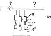
现在参见图10a,示出了在用于沿两个或更多个轴移动物体的系统的实施方式中的阀歧管13的示意图1000。阀歧管13通常将具有用于将压力变换器44连接至流体可膨胀容器9的压力变换器端口,排气电磁阀端口43以及膨胀电磁阀端口45。可膨胀容器9可以包括膨胀源,该膨胀源通常包括用于使每个流体容器9加压和减压的软管20和压缩机40。容器或在其中的密封副室将包括膨胀源,该膨胀源通常包括用于使每个流体容器9加压和减压的软管20和压缩机40。除了压缩机之外,流体容器9可以由其他装置(诸如空气释放阀)减压。单个三通阀42可以利用一些阀或每个容器一个阀来提供膨胀和缩小。诸如当在正常状态下在地面上使用系统时,用于沿两个或更多个轴移动物体的系统的一些实施方式在膨胀时可以允许过量空气能够过多地流入大气中。如图10b所示,因为在地表层大气、空间中的应用和水下应用可能需要在封闭系统中再使用所有可利用的空气,所以系统的其它实施方式可以允许空气能够从一个容器流到另一个容器或者存储槽内。Referring now to Figure 10a, there is shown a schematic diagram 1000 of the
现在参见图10b,示出了与通过计算机可以被可变控制的三通控制阀42和用于使每个流体容器加压和减压的压缩机40相连接的、用于沿两个或更多个轴移动物体的系统的实施方式中的阀歧管13的示意图1050。本示例性实施方式中的歧管还包括显示为与流体可膨胀容器9相连接的压力变换器44。排气被显示出为再循环至压缩机40中的进口。Referring now to FIG. 10b, there is shown a three-
图11示出了用于沿两个或更多个轴移动物体的系统的独立定位动力控制单元14的方块图1100,该独立定位动力控制单元14被显示为定位在本示例性实施方式的图1中的中央支承结构11的基部处。该控制单元14可以包括:导向系统,该导向系统包括传感器(诸如激光瞄准传感器51、电子水平传感器52、GPS传感器53、环境温度传感器54);控制计算机,该控制计算机包括用于在移动应用物3a时控制流体可膨胀容器9的计算机的硬件和软件50。通过处理来自电子压力传感器55(该电子压力传感器55可以在流体可膨胀容器的任何部分上与流体可膨胀容器中的每一个相连接)、环境温度传感器54以及电子水平传感器52(用于检测高度和方位角)的信息,计算机50控制每个流体可膨胀容器9以将上支承结构4并且因此将物体或应用物3a移动到希望的位置以维持相对于目标的最优方位。FIG. 11 shows a block diagram 1100 of an independent positioning
另外,计算机50可以计算应用物3a或上支承结构4的当前位置,确定为移动应用物3a所必需的空气体积和压力变化,并且致动阀和歧管系统以将压缩空气泵送入那些需要充气的流体可膨胀容器9中并且同时从那些需要放气的容器中释放空气,以便将物体或应用物9致动或驱动或移到希望的位置。通过电子地致动压缩机40和控制阀42,同时通过评价从电子水平传感器52处获得的反馈来比较并且矫正支承结构4的运动,该计算机实现流体可膨胀容器9的充气和放气。In addition, the computer 50 can calculate the current position of the
控制单元还包括板上电源15、压缩机以及用于发送和接收信号到控制计算机50的阀控制诊断部件57。控制计算机50从传感器接收信号以确定用于控制致动器9的命令。控制计算机50利用包括WiFI和/或WiMax的当前电信标准将运动命令56输出至遥控系统。The control unit also includes an on-
现在参见图12,示出了用于沿两个或更多个轴移动物体的系统的供电系统15的方块图1200。供电系统15可以包括光伏板60,该光伏板60安装在与控制电池62的充电控制器61相连接的应用物支承3b上。充电控制器还控制供给控制板64的电力以给用于系统的计算机和通信提供电力。控制板64还控制供给电路和其他传感器65以及系统的控制阀63的电力。Referring now to FIG. 12 , there is shown a block diagram 1200 of the
最后,在一些用于沿两个或更多个轴移动物体的系统的实施方式中,用于支承结构的原动力可以由任何类型的具有或不具有压缩流体存储器的流体泵或压缩机提供。在一些实施方式中,流体可以由需要比高压压缩机更少的电力的一个或更多个小且有效的叶轮式压缩机提供。因而,小太阳电池板或电池可以提供足以用于定位应用物3a的整个表面的电力,并且也给控制和通信单元提供电力,而避免在将外部电源联接至系统所固有的大资本费用。Finally, in some embodiments of the system for moving objects along two or more axes, the motive force for the support structure may be provided by any type of fluid pump or compressor with or without a compressed fluid reservoir. In some embodiments, fluid may be provided by one or more small and efficient vane compressors that require less power than high pressure compressors. Thus, a small solar panel or battery can provide sufficient power for positioning the entire surface of the
用于沿两个或更多个轴移动物体的系统的其他示例性实施方式包括在航空宇宙、天文学以及电信中的应用(诸如红外成像传感器、电磁辐射天线或发射器、望远镜以及传感器阵列的受控定位)。例如,图13a示出了跟踪通信卫星接收天线71的用于沿两个或更多个轴70移动物体的系统的立体图1300。Other exemplary embodiments of systems for moving objects along two or more axes include applications in aerospace, astronomy, and telecommunications, such as infrared imaging sensors, electromagnetic radiation antennas or transmitters, telescopes, and sensor arrays. control positioning). For example, FIG. 13 a shows a
图13b示出了在需要机械手或致动器的应用中用在太空交通工具72或空间站上的用于沿两个或更多个轴移动物体的系统的立体图1310。Figure 13b shows a
此外,图13c示出了用于旋转与辐射源或接收器对准的天线或传感器或太阳电池板74的用于沿两个或更多个轴移动物体的系统的立体图1320。Furthermore, Figure 13c shows a
图13d示出了作为在太空中的行星上,例如在火星上从太阳73收集太阳能以为火星基地提供加热的定日镜70配置的用于沿两个或更多个轴移动物体的系统的立体图1330。Figure 13d shows a perspective view of a system for moving objects along two or more axes configured as
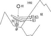
图14a和14b分别示出了实施为为温室照明装置80和实施为用于居住或商业建筑或用于照明其他的阴暗公共区域的照明或供暖系统的用于相对于太阳73沿两个或更多个轴移动物体的系统70的立体图1400和1450。Figures 14a and 14b show, respectively, a lighting or heating system implemented as a
用于沿两个或更多个轴移动物体的系统的另一个实施方式是医学和生物医学领域,其中致动器可以在各种实施方式中以各种规模建立,而用于医疗卫生器材、诊断机械和机器人、外部或内部假肢或假体性植入物,以及用于最低程度侵入的装置和显微外科应用(诸如无菌盐水或其他适当的液体或流体可以被用来驱动致动器的血管腔内手术、支气管内手术以及内窥镜检查手术)。Another embodiment of a system for moving an object along two or more axes is the field of medicine and biomedicine, where actuators can be built in various embodiments and at various scales for use in medical and health equipment, Diagnostic machinery and robotics, external or internal prosthetics or prosthetic implants, and devices for minimally invasive and microsurgical applications (such as sterile saline or other appropriate fluids or fluids can be used to drive actuators endovascular, endobronchial, and endoscopic procedures).
参见图15a,示出了实施为医疗机器人致动器70的用于沿两个或更多个轴移动物体的系统的立体图1500。Referring to Fig. 15a, a
参见图15b,示出了实施为用于失去的肢的假肢105的用于沿两个或更多个轴移动物体的系统70的立体图1550。Referring to Fig. 15b, a
现在参见图15c,示出了实施为用于各种类型的手术(诸如通过例如腹腔镜的血管腔内手术或显微手术)的显微手术操纵器1555的用于沿两个或更多个轴移动物体的系统70的立体图。Referring now to FIG. 15c, there is shown a
现在参见图15d,示出了被用以定位用于治疗人110的辐射源70的用于沿两个或更多个轴移动物体的系统的立体图1560。Referring now to FIG. 15d, there is shown a perspective view 1560 of a system for moving an object along two or more axes used to position a
用于沿两个或更多个轴移动物体的系统可以是以下实施方式,即该实施方式包括诸如用于总贸易、土木工程以及制造业的所有其他各种应用,其中装置被配置成定位例如广告材料、施工设备、或其他贸易或娱乐或生活消费品(诸如庭院伞、遮阳伞)、或任何其他的小的或大的物体。该系统也可以用于或适于包括水下和不开挖或隧道技术的遥控或机器人用途,以定位在上面未命名的许多制造业、基础设施以及贸易背景中的任何尺寸或从宏观尺度到纳米技术尺度的任何尺度的用于处理、检查、制作、修理以及遥控操作的工具、材料以及机器。A system for moving an object along two or more axes may be an embodiment including all other various applications such as for general trade, civil engineering, and manufacturing, where the device is configured to position e.g. Advertising material, construction equipment, or other trade or recreational or consumer goods (such as patio umbrellas, parasols), or any other small or large objects. The system may also be used or adapted for remote-controlled or robotic use including underwater and trenchless or tunneling to locate any size or from macro scale to Tools, materials, and machines for handling, inspection, fabrication, repair, and remote manipulation of any scale at the nanotechnology scale.
现在参见图16,示出了用于沿两个或更多个轴移动物体的方法的流程图250。该示例性方法包括提供至少两个流体容器,提供枢转点7(图1),提供导向系统,该导向系统检测位置变化需要(步骤251)并且将数据信号发送到控制单元14(步骤252),该控制单元14解释数据信号并且将数据信号转换成用于压力变化或流体体积变化的命令(步骤253)。控制单元14通过信号致动一个或更多个泵以改变流体容器9中的一个或更多个中的流体的体积和压力(步骤254)。流体容器中的一个或更多个容器的体积变化导致压力变化(步骤255),该压力变化移动物体3a。通过利用加压流体在一个或更多个位置处将压力施加在物体上,或者通过改变加压流体的体积来改变施加在某一位置处的压力,可以移动物体或应用物3a。用于沿两个或更多个轴移动物体的方法的示例性实施方式包括将压力施加在物体3a的三个位置上。可以由三个位置形成枢转点,而无需机械支点或支承。Referring now to FIG. 16 , a
参考附图描述了用于沿两个或更多个轴移动物体的示例性系统的实施方式,在附图中示出了一些但不是全部的用于沿两个或更多个轴移动物体的系统的实施方式。用于沿两个或更多个轴移动物体的系统可以以许多不同的形式来实施,并且不应该被解释为限于本文提出的实施方式。附图/图不必按比例绘制或成比例,并且为清楚起见,用于沿两个或更多个轴移动物体的系统的某些特征可能会被扩大比例地示出或者某种程度上以示意性的形式示出。Embodiments of exemplary systems for moving objects along two or more axes are described with reference to the accompanying drawings, in which some, but not all, embodiments for moving objects along two or more axes are shown. Implementation of the system. A system for moving an object along two or more axes may be implemented in many different forms and should not be construed as limited to the implementations set forth herein. The drawings/figures are not necessarily to scale or scale, and certain features of systems for moving objects along two or more axes may be shown exaggerated in scale or somewhat schematically for the sake of clarity The sexual form is shown.
在前面的详述中,参照具体的示例性实施方式描述了根据用于沿两个或更多个轴移动物体的系统的实施方式的系统和方法。因此,本说明书和附图被认为是说明性的而非限制性的。通过附加于此的几个实施例并且通过它们的等同例进一步理解用于沿两个或更多个轴移动物体的系统的范围。In the foregoing detailed description, systems and methods according to embodiments of a system for moving an object along two or more axes have been described with reference to specific exemplary embodiments. Accordingly, the specification and drawings are to be regarded as illustrative rather than restrictive. The scope of the system for moving an object along two or more axes is further appreciated by the several embodiments appended hereto and by their equivalents.
此外,在描述各种实施方式期间,说明书可能以具体的一系列步骤来阐述方法和/或过程。然而,如果方法或过程不依赖本文提出的步骤的具体顺序方面,则方法或过程不应限于描述的具体的一系列步骤。作为本领域技术人员应该理解,其他顺序的步骤可以是可能的。因此,说明书中提出的步骤的具体顺序不应被解释为对权利要求的限制。另外,涉及方法/或过程的权利要求不应该限于以描写顺序执行它们的步骤,并且本领域技术人员可以容易地理解可以被改变执行顺序并且仍保持在各种实施方式的精神和范围内。Additionally, during descriptions of various embodiments, the specification may have set forth methods and/or processes as a specific series of steps. However, if the method or process does not rely on the specific order aspects of the steps presented herein, the method or process should not be limited to the specific series of steps described. As will be appreciated by those skilled in the art, other sequences of steps may be possible. Therefore, the specific order of the steps presented in the specification should not be construed as limitations on the claims. Additionally, claims directed to methods and/or processes should not be limited to the execution of their steps in the order of description, and those skilled in the art will readily appreciate that the order of execution can be altered and still remain within the spirit and scope of the various embodiments.
Claims (36)
Applications Claiming Priority (3)
| Application Number | Priority Date | Filing Date | Title |
|---|---|---|---|
| US6435108P | 2008-02-29 | 2008-02-29 | |
| US61/064,351 | 2008-02-29 | ||
| PCT/US2008/006660WO2009108159A1 (en) | 2008-02-29 | 2008-05-23 | Multi-axis metamorphic actuator and drive system and method |
Publications (2)
| Publication Number | Publication Date |
|---|---|
| CN102016382Atrue CN102016382A (en) | 2011-04-13 |
| CN102016382B CN102016382B (en) | 2013-10-16 |
Family
ID=41016372
Family Applications (1)
| Application Number | Title | Priority Date | Filing Date |
|---|---|---|---|
| CN2008801287410AExpired - Fee RelatedCN102016382B (en) | 2008-02-29 | 2008-05-23 | Multi-axis metamorphic actuator and drive system and method |
Country Status (6)
| Country | Link |
|---|---|
| US (1) | US20110114080A1 (en) |
| EP (1) | EP2255122A4 (en) |
| CN (1) | CN102016382B (en) |
| AU (1) | AU2008351434A1 (en) |
| MX (1) | MX2010009438A (en) |
| WO (1) | WO2009108159A1 (en) |
Cited By (14)
| Publication number | Priority date | Publication date | Assignee | Title |
|---|---|---|---|---|
| CN103049000A (en)* | 2012-12-20 | 2013-04-17 | 东南大学 | Hourglass type photovoltaic power generation device |
| CN105300369A (en)* | 2015-10-26 | 2016-02-03 | 马国才 | Multi-shaft structure of electronic system |
| CN106002866A (en)* | 2016-07-25 | 2016-10-12 | 青岛海腾达机械科技有限公司 | Equipment support table assembly provided with safety light |
| CN107255213A (en)* | 2017-06-28 | 2017-10-17 | 山东省农业机械科学研究院 | Photoelectric sensor accurate adjustment support |
| CN108873240A (en)* | 2018-06-28 | 2018-11-23 | 中国科学院国家天文台南京天文光学技术研究所 | The rotary positioning apparatus and control method of astronomical telescope third reflecting mirror |
| CN108969210A (en)* | 2018-06-28 | 2018-12-11 | 吉林大学 | Self-balancing stretcher mechanism is rescued after a kind of shake |
| CN109515675A (en)* | 2018-11-28 | 2019-03-26 | 北京航空航天大学 | The over all Integration assembly apparatus and method for of stratosphere aerostatics solar array |
| CN110155900A (en)* | 2019-06-19 | 2019-08-23 | 中国建筑第八工程局有限公司 | Adaptive thrustor and its application method |
| CN111900918A (en)* | 2015-01-30 | 2020-11-06 | 森福鼎股份有限公司 | Fluidic actuator system and method |
| CN112054588A (en)* | 2020-09-10 | 2020-12-08 | 四川大学 | A wind-solar hybrid power generation system |
| CN113638526A (en)* | 2021-08-10 | 2021-11-12 | 正兴建设集团股份有限公司 | Photovoltaic energy-saving curtain wall and construction method thereof |
| TWI770593B (en)* | 2020-08-26 | 2022-07-11 | 財團法人工業技術研究院 | Support structure |
| CN116398771A (en)* | 2023-04-26 | 2023-07-07 | 广船国际有限公司 | Flame detector for ship |
| CN118232808A (en)* | 2024-05-22 | 2024-06-21 | 安徽千寻工程科技有限公司 | Photovoltaic power distribution energy storage device |
Families Citing this family (38)
| Publication number | Priority date | Publication date | Assignee | Title |
|---|---|---|---|---|
| WO2009145266A1 (en)* | 2008-05-28 | 2009-12-03 | シャープ株式会社 | Tracking type solar power generation system, and tracking control method and tracking discrepancy correcting method for the tracking type solar power generation system |
| DE102009052442A1 (en)* | 2009-11-10 | 2011-05-12 | Kornelia Tebbe | Solar panel assembly and machine for handling such |
| US8168931B1 (en)* | 2009-12-09 | 2012-05-01 | Concrete Systems, Inc. | Solar tracking device |
| ES2705209T3 (en)* | 2009-12-31 | 2019-03-22 | Saint Gobain Performance Plastics Pampus Gmbh | Renewable energy source that includes an energy conversion structure and a bearing component |
| US20110168232A1 (en)* | 2010-01-14 | 2011-07-14 | Solaria Corporation | Method and System for Providing Tracking for Concentrated Solar Modules |
| DE102010010169A1 (en)* | 2010-03-03 | 2011-09-08 | Solardynamik Gmbh | A dynamic carrier system for flexible or rigid solar cells for self-sufficient and optimal power generation with polymer-based compressed air and sensor technology |
| DE102010012805A1 (en)* | 2010-03-23 | 2011-09-29 | Solardynamik Gmbh | Carrier system for flexible or rigid solar energy conversion units such as solar cells, has one or multiple inflatable elements which are changeable in its volumes controlled from each other by compressed air supply |
| US8375935B2 (en)* | 2010-06-08 | 2013-02-19 | Fung Gin Da Energy Science And Technology Co., Ltd. | Water heating apparatus using solar power |
| US9978900B2 (en)* | 2011-05-13 | 2018-05-22 | Ormat Technologies, Inc. | Heliostat system and method of using same |
| US20130061845A1 (en)* | 2011-09-12 | 2013-03-14 | Zomeworks Corporation | Radiant energy driven orientation system |
| US10965241B2 (en)* | 2012-02-05 | 2021-03-30 | Tien Solar LLC | Solar plant support structure |
| CN102778899B (en)* | 2012-07-27 | 2015-01-21 | 浙江中控太阳能技术有限公司 | Mirror field dispatching system and method for tower type solar thermal power generation system |
| DE102012111704B4 (en)* | 2012-09-04 | 2017-07-13 | Miro Gudzulic | Actuator and solar system |
| US10605365B1 (en) | 2012-10-26 | 2020-03-31 | Other Lab, Llc | Fluidic actuator |
| US20140166076A1 (en)* | 2012-12-17 | 2014-06-19 | Masimo Semiconductor, Inc | Pool solar power generator |
| US9784476B2 (en) | 2013-05-30 | 2017-10-10 | Howard Stein | Portable solar tracker |
| US9605880B2 (en)* | 2013-07-18 | 2017-03-28 | George A. Van Straten | Heated solar panel system |
| JP2015124928A (en)* | 2013-12-26 | 2015-07-06 | 三鷹光器株式会社 | Multi-mirror type heliostat |
| US9255725B2 (en)* | 2014-01-30 | 2016-02-09 | Jasem M K Th Sh Al-Enizi | Sun tracking solar energy collection system |
| NL1040816B1 (en)* | 2014-05-23 | 2016-03-15 | Vincentius Carolus Maria Peters Ir | Object tracking device. |
| CN104020789B (en)* | 2014-06-25 | 2017-01-18 | 兰州理工大学 | Solar two-shaft tracking device driven by single thermal expander |
| USD783522S1 (en)* | 2015-05-14 | 2017-04-11 | James Francis Cameron | Solar panel arrangement |
| US10562180B2 (en) | 2016-03-29 | 2020-02-18 | Other Lab, Llc | Fluidic robotic actuator system and method |
| DE102017106522A1 (en) | 2017-03-27 | 2018-09-27 | European Transonic Windtunnel Gmbh | Device for adjusting the angular position of a control surface |
| DE102017106604A1 (en)* | 2017-03-28 | 2018-10-04 | Miro Gudzulic | Actuator and solar system |
| EP3613140A4 (en)* | 2017-04-17 | 2021-01-06 | Sunfolding, Inc. | CONTROL SYSTEM AND PROCEDURES FOR SOLDIERS |
| CN107222165A (en)* | 2017-07-06 | 2017-09-29 | 北京铂阳顶荣光伏科技有限公司 | Road surface electricity generation system with heater |
| US10190801B1 (en)* | 2017-10-17 | 2019-01-29 | King Saud University | Solar heating apparatus |
| EP3483522A1 (en)* | 2017-11-14 | 2019-05-15 | ETH Zurich | Actuator, mechanism comprising the actuator, solar energy harnessing apparatus, arrangement of buildings, and a method for manufacturing the actuator |
| US11502639B2 (en) | 2018-05-29 | 2022-11-15 | Sunfolding, Inc. | Tubular fluidic actuator system and method |
| JP6535402B1 (en)* | 2018-05-31 | 2019-06-26 | 株式会社SolarFlame | Sun tracking device |
| US20190368779A1 (en)* | 2018-05-31 | 2019-12-05 | Pang Mei Sport Co., Ltd. | Solar device |
| FR3099666B1 (en)* | 2019-07-31 | 2022-04-15 | Commissariat Energie Atomique | Photovoltaic module, associated manufacturing process and integration system |
| US11683003B2 (en) | 2020-06-22 | 2023-06-20 | Sunfolding, Inc. | Locking, dampening and actuation systems and methods for solar trackers |
| CN116964928A (en) | 2021-04-16 | 2023-10-27 | 美国圣戈班性能塑料公司 | Bearing assembly for tracker assembly and method of making and using the same |
| US20230139980A1 (en)* | 2021-11-02 | 2023-05-04 | Sunfolding, Inc. | Inflatable bladder system and method |
| US12104631B1 (en)* | 2022-06-01 | 2024-10-01 | Earl M. Harris, III | Inflatable clamping apparatus and system for securely supporting an object on an elongated member |
| WO2025073670A1 (en)* | 2023-10-06 | 2025-04-10 | Leibniz-Institut Für Astrophysik Potsdam (Aip) | Positioning device for positioning a plurality of sensor and / or effector devices |
Family Cites Families (23)
| Publication number | Priority date | Publication date | Assignee | Title |
|---|---|---|---|---|
| GB1562912A (en)* | 1977-05-31 | 1980-03-19 | Standard Telephones Cables Ltd | Automatic heliostat mechanism |
| SU1346918A1 (en)* | 1985-11-05 | 1987-10-23 | Научно-Исследовательский И Проектно-Конструкторский Институт Плодоовощного Хозяйства | Solar heat collector |
| US4762298A (en)* | 1987-03-23 | 1988-08-09 | The United States Of America As Represented By The United States Department Of Energy | Support and maneuvering device |
| HU51370A (en)* | 1988-01-22 | 1990-04-30 | ||
| US5227618A (en)* | 1992-02-28 | 1993-07-13 | Jefferson Shingleton | Variably pressurable support and tracking apparatus and method for tracking moving radiation source |
| US5871255A (en)* | 1997-01-06 | 1999-02-16 | Chrysler Corporation | Vehicle seat |
| JPH11125765A (en)* | 1997-08-22 | 1999-05-11 | Nippon Telegr & Teleph Corp <Ntt> | Tracking type solar power generation device and solar tracking device |
| US6345826B1 (en)* | 2000-06-23 | 2002-02-12 | Meritor Heavy Vehicle Systems, Llc | Driveline angle control assembly and method for controlling driveline angles in a vehicle |
| US6498290B1 (en)* | 2001-05-29 | 2002-12-24 | The Sun Trust, L.L.C. | Conversion of solar energy |
| US6555739B2 (en)* | 2001-09-10 | 2003-04-29 | Ekla-Tek, Llc | Photovoltaic array and method of manufacturing same |
| JP3855160B2 (en)* | 2002-03-25 | 2006-12-06 | 幹夫 木下 | Solar radiation concentrator |
| PT1604407E (en)* | 2003-03-18 | 2009-07-29 | Sunpower Corp Systems | Tracking solar collector assembly |
| US7094157B2 (en)* | 2003-07-22 | 2006-08-22 | Oceaneering International, Inc. | Amusement ride vehicle with pneumatically actuated cabin and motion base |
| ES2277483B1 (en)* | 2004-07-02 | 2008-06-01 | Sebastian Fiol Monserrat | AUTOMATIC PERFECTED ORIENTATION DEVICE FOR SOLAR ENERGY PLATES. |
| US20060058716A1 (en)* | 2004-09-14 | 2006-03-16 | Hui John C K | Unitary external counterpulsation device |
| US8528541B2 (en)* | 2005-01-31 | 2013-09-10 | Seesean, Inc. | Solar collection apparatus and methods |
| US8065951B2 (en)* | 2005-02-15 | 2011-11-29 | P.I. Engineering, Inc. | Servo-controlled tipping platform and motion control system therefor |
| KR100727803B1 (en)* | 2005-10-24 | 2007-06-13 | 홍정호 | Solar location tracking method of solar collector or solar collector and its device |
| US20080057776A1 (en)* | 2006-08-23 | 2008-03-06 | Coolearth Solar | Low-cost interconnection system for solar energy modules and ancillary equipment |
| US20080115823A1 (en)* | 2006-11-21 | 2008-05-22 | Kinsey Geoffrey S | Curved focal plane receiver for concentrating light in a photovoltaic system |
| CN101054957A (en)* | 2007-03-13 | 2007-10-17 | 张金祥 | Solar energy driven machine |
| US7645931B2 (en)* | 2007-03-27 | 2010-01-12 | Gm Global Technology Operations, Inc. | Apparatus to reduce the cost of renewable hydrogen fuel generation by electrolysis using combined solar and grid power |
| CN101046191A (en)* | 2007-05-08 | 2007-10-03 | 王宝瑞 | Solar energy induced airflow power generating system |
- 2008
- 2008-05-23CNCN2008801287410Apatent/CN102016382B/ennot_activeExpired - Fee Related
- 2008-05-23WOPCT/US2008/006660patent/WO2009108159A1/enactiveApplication Filing
- 2008-05-23USUS12/919,795patent/US20110114080A1/ennot_activeAbandoned
- 2008-05-23AUAU2008351434Apatent/AU2008351434A1/ennot_activeAbandoned
- 2008-05-23EPEP08754716.2Apatent/EP2255122A4/ennot_activeWithdrawn
- 2008-05-23MXMX2010009438Apatent/MX2010009438A/ennot_activeApplication Discontinuation
Cited By (19)
| Publication number | Priority date | Publication date | Assignee | Title |
|---|---|---|---|---|
| CN103049000B (en)* | 2012-12-20 | 2015-01-28 | 东南大学 | Hourglass type photovoltaic power generation device |
| CN103049000A (en)* | 2012-12-20 | 2013-04-17 | 东南大学 | Hourglass type photovoltaic power generation device |
| CN111900918A (en)* | 2015-01-30 | 2020-11-06 | 森福鼎股份有限公司 | Fluidic actuator system and method |
| CN105300369A (en)* | 2015-10-26 | 2016-02-03 | 马国才 | Multi-shaft structure of electronic system |
| CN106002866A (en)* | 2016-07-25 | 2016-10-12 | 青岛海腾达机械科技有限公司 | Equipment support table assembly provided with safety light |
| CN106002866B (en)* | 2016-07-25 | 2018-07-31 | 金华天阳机械股份有限公司 | A kind of equipment supporting table component with green indicating lamp |
| CN107255213A (en)* | 2017-06-28 | 2017-10-17 | 山东省农业机械科学研究院 | Photoelectric sensor accurate adjustment support |
| CN108873240A (en)* | 2018-06-28 | 2018-11-23 | 中国科学院国家天文台南京天文光学技术研究所 | The rotary positioning apparatus and control method of astronomical telescope third reflecting mirror |
| CN108969210A (en)* | 2018-06-28 | 2018-12-11 | 吉林大学 | Self-balancing stretcher mechanism is rescued after a kind of shake |
| CN109515675A (en)* | 2018-11-28 | 2019-03-26 | 北京航空航天大学 | The over all Integration assembly apparatus and method for of stratosphere aerostatics solar array |
| CN110155900A (en)* | 2019-06-19 | 2019-08-23 | 中国建筑第八工程局有限公司 | Adaptive thrustor and its application method |
| CN110155900B (en)* | 2019-06-19 | 2024-04-26 | 中国建筑第八工程局有限公司 | Self-adaptive pushing device and application method thereof |
| TWI770593B (en)* | 2020-08-26 | 2022-07-11 | 財團法人工業技術研究院 | Support structure |
| CN112054588A (en)* | 2020-09-10 | 2020-12-08 | 四川大学 | A wind-solar hybrid power generation system |
| CN112054588B (en)* | 2020-09-10 | 2022-06-21 | 四川大学 | Wind-solar hybrid power generation system |
| CN113638526A (en)* | 2021-08-10 | 2021-11-12 | 正兴建设集团股份有限公司 | Photovoltaic energy-saving curtain wall and construction method thereof |
| CN116398771A (en)* | 2023-04-26 | 2023-07-07 | 广船国际有限公司 | Flame detector for ship |
| CN118232808A (en)* | 2024-05-22 | 2024-06-21 | 安徽千寻工程科技有限公司 | Photovoltaic power distribution energy storage device |
| CN118232808B (en)* | 2024-05-22 | 2024-07-19 | 安徽千寻工程科技有限公司 | Photovoltaic power distribution energy storage device |
Also Published As
| Publication number | Publication date |
|---|---|
| AU2008351434A1 (en) | 2009-09-03 |
| CN102016382B (en) | 2013-10-16 |
| WO2009108159A1 (en) | 2009-09-03 |
| EP2255122A4 (en) | 2013-12-18 |
| EP2255122A1 (en) | 2010-12-01 |
| US20110114080A1 (en) | 2011-05-19 |
| MX2010009438A (en) | 2011-03-11 |
Similar Documents
| Publication | Publication Date | Title |
|---|---|---|
| CN102016382A (en) | Multi-axis metamorphic actuator and drive system and method | |
| US9140403B2 (en) | Single-axis drive system and method | |
| US8943817B2 (en) | Non-linear actuator system and method | |
| US5404868A (en) | Apparatus using a balloon supported reflective surface for reflecting light from the sun | |
| US8511297B2 (en) | Actuator-based drive system for solar collector | |
| US4762298A (en) | Support and maneuvering device | |
| WO2006052802A2 (en) | Positioning system and method of orienting an object using same | |
| KR20150085056A (en) | Hexapod system | |
| AU2010200072B2 (en) | Low-Cost Heliostatic Mirror with Protective Inflation Stabilizable Surface Element Means | |
| CN114050776A (en) | Photovoltaic power generation device and photovoltaic power generation system | |
| US20100024802A1 (en) | Heliostat support and drive mechanism | |
| US8231222B2 (en) | Heliostat with actively controlled liquid ballast system | |
| Cassell et al. | Design and execution of the hypersonic inflatable aerodynamic decelerator large-article wind tunnel experiment | |
| CN105227081A (en) | A kind of with fascinating and the fan out formula device of solar generating of revolute function | |
| WO2020069725A1 (en) | Floating wave energy converter | |
| EP3710760B1 (en) | Actuator, mechanism comprising the actuator, solar energy harnessing apparatus, arrangement of buildings, and a method for manufacturing the actuator | |
| JP5783050B2 (en) | Solar panel unit | |
| Norton-Cormier et al. | Designing and constructing an alternative reduced-cost heliostat drive system | |
| Busby et al. | SOL: A Compact, Portable, Telescopic, Soft-Robotic Sun-Tracking Mechanism for Improved Solar Power Production | |
| TWM673795U (en) | Synchronized solar tracking system for a solar power generation device | |
| GB2451660A (en) | Heat to kinetic energy converter | |
| Beveridge | Parabolic Dish Concentrator Designs and Concepts |
Legal Events
| Date | Code | Title | Description |
|---|---|---|---|
| C06 | Publication | ||
| PB01 | Publication | ||
| C10 | Entry into substantive examination | ||
| SE01 | Entry into force of request for substantive examination | ||
| C14 | Grant of patent or utility model | ||
| GR01 | Patent grant | ||
| CF01 | Termination of patent right due to non-payment of annual fee | ||
| CF01 | Termination of patent right due to non-payment of annual fee | Granted publication date:20131016 Termination date:20160523 |