CN102015221B - A method and a system for determining the relation between a robot coordinate system and a local coordinate system located in the working range of the robot - Google Patents
A method and a system for determining the relation between a robot coordinate system and a local coordinate system located in the working range of the robotDownload PDFInfo
- Publication number
- CN102015221B CN102015221BCN2008801289416ACN200880128941ACN102015221BCN 102015221 BCN102015221 BCN 102015221BCN 2008801289416 ACN2008801289416 ACN 2008801289416ACN 200880128941 ACN200880128941 ACN 200880128941ACN 102015221 BCN102015221 BCN 102015221B
- Authority
- CN
- China
- Prior art keywords
- robot
- calibration object
- sphere
- coordinate system
- calibration
- Prior art date
- Legal status (The legal status is an assumption and is not a legal conclusion. Google has not performed a legal analysis and makes no representation as to the accuracy of the status listed.)
- Expired - Fee Related
Links
- 238000000034methodMethods0.000titleclaimsabstractdescription29
- 238000005259measurementMethods0.000claimsdescription8
- 230000033001locomotionEffects0.000description4
- 238000009434installationMethods0.000description3
- 238000003754machiningMethods0.000description3
- 230000006870functionEffects0.000description2
- 230000007774longtermEffects0.000description2
- 238000004519manufacturing processMethods0.000description2
- 230000009466transformationEffects0.000description2
- 238000004422calculation algorithmMethods0.000description1
- 238000004364calculation methodMethods0.000description1
- 238000004891communicationMethods0.000description1
- 238000004590computer programMethods0.000description1
- 230000004807localizationEffects0.000description1
- 239000000523sampleSubstances0.000description1
Images


Classifications
- B—PERFORMING OPERATIONS; TRANSPORTING
- B25—HAND TOOLS; PORTABLE POWER-DRIVEN TOOLS; MANIPULATORS
- B25J—MANIPULATORS; CHAMBERS PROVIDED WITH MANIPULATION DEVICES
- B25J9/00—Programme-controlled manipulators
- B25J9/16—Programme controls
- B25J9/1679—Programme controls characterised by the tasks executed
- B25J9/1692—Calibration of manipulator
- G—PHYSICS
- G05—CONTROLLING; REGULATING
- G05B—CONTROL OR REGULATING SYSTEMS IN GENERAL; FUNCTIONAL ELEMENTS OF SUCH SYSTEMS; MONITORING OR TESTING ARRANGEMENTS FOR SUCH SYSTEMS OR ELEMENTS
- G05B19/00—Programme-control systems
- G05B19/02—Programme-control systems electric
- G05B19/18—Numerical control [NC], i.e. automatically operating machines, in particular machine tools, e.g. in a manufacturing environment, so as to execute positioning, movement or co-ordinated operations by means of programme data in numerical form
- G05B19/401—Numerical control [NC], i.e. automatically operating machines, in particular machine tools, e.g. in a manufacturing environment, so as to execute positioning, movement or co-ordinated operations by means of programme data in numerical form characterised by control arrangements for measuring, e.g. calibration and initialisation, measuring workpiece for machining purposes
- G05B19/4015—Numerical control [NC], i.e. automatically operating machines, in particular machine tools, e.g. in a manufacturing environment, so as to execute positioning, movement or co-ordinated operations by means of programme data in numerical form characterised by control arrangements for measuring, e.g. calibration and initialisation, measuring workpiece for machining purposes going to a reference at the beginning of machine cycle, e.g. for calibration
- G—PHYSICS
- G05—CONTROLLING; REGULATING
- G05B—CONTROL OR REGULATING SYSTEMS IN GENERAL; FUNCTIONAL ELEMENTS OF SUCH SYSTEMS; MONITORING OR TESTING ARRANGEMENTS FOR SUCH SYSTEMS OR ELEMENTS
- G05B2219/00—Program-control systems
- G05B2219/30—Nc systems
- G05B2219/39—Robotics, robotics to robotics hand
- G05B2219/39021—With probe, touch reference positions
- G—PHYSICS
- G05—CONTROLLING; REGULATING
- G05B—CONTROL OR REGULATING SYSTEMS IN GENERAL; FUNCTIONAL ELEMENTS OF SUCH SYSTEMS; MONITORING OR TESTING ARRANGEMENTS FOR SUCH SYSTEMS OR ELEMENTS
- G05B2219/00—Program-control systems
- G05B2219/30—Nc systems
- G05B2219/50—Machine tool, machine tool null till machine tool work handling
- G05B2219/50026—Go to reference plane, cube
- G—PHYSICS
- G05—CONTROLLING; REGULATING
- G05B—CONTROL OR REGULATING SYSTEMS IN GENERAL; FUNCTIONAL ELEMENTS OF SUCH SYSTEMS; MONITORING OR TESTING ARRANGEMENTS FOR SUCH SYSTEMS OR ELEMENTS
- G05B2219/00—Program-control systems
- G05B2219/30—Nc systems
- G05B2219/50—Machine tool, machine tool null till machine tool work handling
- G05B2219/50036—Find center of circular mark, groove
Landscapes
- Engineering & Computer Science (AREA)
- Robotics (AREA)
- Mechanical Engineering (AREA)
- Human Computer Interaction (AREA)
- Manufacturing & Machinery (AREA)
- Physics & Mathematics (AREA)
- General Physics & Mathematics (AREA)
- Automation & Control Theory (AREA)
- Manipulator (AREA)
- Numerical Control (AREA)
Abstract
Translated fromChineseDescription
Translated fromChinese技术领域technical field
本发明涉及用于确定位于工业机器人工作范围内的本地坐标系与机器人坐标系之间的关系的方法和装置。例如,本发明适于确定在工件坐标系或夹具坐标系与机器人坐标系之间的关系。The invention relates to a method and a device for determining the relationship between a local coordinate system located within the working range of an industrial robot and a robot coordinate system. For example, the invention is suitable for determining the relationship between a workpiece coordinate system or a fixture coordinate system and a robot coordinate system.
背景技术Background technique
在机器人安装和机器人室的试运转方面存在的基本问题是标识出机器人相对于将由该机器人加工的工件的关系。机器人意于在工件上进行加工,并且工件位于机器人的工作范围内。在机器人保持将要加工的工件并且工具位于机器人的工作范围内的情况下,也存在同样的问题。在该情况下,必须标识出工具和机器人之间的关系。A basic problem in robot installation and commissioning of a robot room is identifying the relationship of the robot to the workpiece to be machined by the robot. The robot is intended to perform machining on a workpiece, and the workpiece is located within the working range of the robot. The same problem exists in the case where the robot holds the workpiece to be machined and the tool is within the working range of the robot. In this case, the relationship between tool and robot must be identified.
工件标识的原因在于要限定出工件中的本地坐标系,这可以用于对机器人进行编程以在工件上进行加工。这种方法的两个主要优点在于:编程将在工件的坐标系中完成,这将让编程人员更好理解。另一种方法是将在机器人底座坐标系中对机器人进行编程。The reason for workpiece identification is to define a local coordinate system in the workpiece, which can be used to program the robot to perform machining on the workpiece. Two main advantages of this approach are that the programming will be done in the coordinate system of the workpiece, which will be better understood by the programmer. Another approach is to program the robot in the robot base coordinate system.
但是,这对于编程人员来说将不那么容易理解。如果编程在工件坐标系中完成,则如果机器人和工件之间的关系由于某种原因(例如设备移动)而改变的话,编程也将容易重新使用。重新使用将仅仅包括对机器人坐标系和工件坐标系之间的关系进行新的标识。另外,离线生成的程序的使用将以容易且精确的方式受到支持。However, this will not be so easy for programmers to understand. If the programming is done in the workpiece coordinate system, it will also be easy to reuse if the relationship between the robot and the workpiece changes for some reason, such as equipment movement. Reuse will only consist of a new identification of the relationship between the robot coordinate system and the workpiece coordinate system. In addition, the use of programs generated offline will be supported in an easy and precise manner.
发明内容Contents of the invention
本发明的目的在于提供一种用于确定位于机器人工作范围内的本地坐标系与机器人坐标系之间的关系的方法,该方法简单、快捷并且精确。It is an object of the present invention to provide a method for determining the relationship between a local coordinate system located within the working range of a robot and a robot coordinate system which is simple, fast and precise.
该目的是由如权利要求1所限定的方法来实现。This object is achieved by a method as defined in
这种方法包括:将第一校准物体与所述机器人成固定关系附接,确定所述第一校准物体相对于所述机器人的位置,将至少三个第二校准物体定位在所述机器人的工作范围内,其中至少一个所述校准物体为具有成形为球体的突出部分的凸形校准物体,并且至少一个所述校准物体为包括至少两个非平行倾斜表面的凹形校准物体,所述至少两个非平行倾斜表面布置成用以接收所述球体使得所述球体在至少一个参考位置与所述表面接触,确定出在所述本地坐标系中每个所述第二校准物体的至少一个参考位置,The method includes attaching a first calibration object in fixed relation to the robot, determining a position of the first calibration object relative to the robot, positioning at least three second calibration objects in a working position of the robot Wherein at least one of said calibration objects is a convex calibration object having a protruding portion shaped as a sphere, and at least one of said calibration objects is a concave calibration object comprising at least two non-parallel inclined surfaces, said at least two a non-parallel inclined surface arranged to receive said sphere such that said sphere is in contact with said surface at at least one reference position, at least one reference position of each said second calibration object is determined in said local coordinate system ,
A)使所述机器人以顺应的方式运动,直到所述球体与所述凹形校准物体的表面机械接触;A) moving the robot in a compliant manner until the sphere is in mechanical contact with the surface of the concave calibration object;
B)读取当所述球体与所述表面机械接触时所述机器人的位置,对另一个所述校准物体重复所述步骤A-B,并且基于所述第一校准物体相对于所述机器人的位置、所述第二校准物体在所述本地坐标系中的参考位置以及当所述球体与所述第二校准物体的所述表面机械接触时所述机器人的位置,计算出所述本地坐标系与所述机器人坐标系之间的关系。B) reading the position of the robot when the sphere is in mechanical contact with the surface, repeating steps A-B for another of the calibration objects, and based on the position of the first calibration object relative to the robot, The reference position of the second calibration object in the local coordinate system and the position of the robot when the sphere is in mechanical contact with the surface of the second calibration object, the relationship between the local coordinate system and the Describe the relationship between the robot coordinate system.
本发明支持自动、快速、容易并且精确标识出用于计算所述本地坐标系的位置。该方法适于由机器人自身自动地执行。可以将该机器人编程为将所述第一校准物体移动到所述第二校准物体,并且进一步移动直到所述球体与所述表面机械接触,并且相应地球体位于参考位置。The invention supports automatic, fast, easy and precise identification of the positions used to calculate the local coordinate system. The method is adapted to be performed automatically by the robot itself. The robot may be programmed to move the first calibration object to the second calibration object and further until the spheres are in mechanical contact with the surface and the respective globe is at a reference position.
该机器人设有自搜索能力,例如采用力控制或柔性伺服系统,这使机器人以顺应的方式运动直到所述球体与所述凹形校准物体的所述表面接触。在具有能够方便快捷使用的自动标识功能时,就能够反复标识出在工件和机器人之间的关系,从而寻找出由于温度改变而造成的长期变化以及偏差。根据本发明的该方法对于初始标识关系以及对长期变化和温度漂移保持跟踪和补偿是有用的。The robot is provided with a self-seeking capability, eg using force control or flexible servos, which causes the robot to move in a compliant manner until the sphere is in contact with the surface of the concave calibration object. With the automatic marking function that can be used quickly and easily, it is possible to repeatedly mark the relationship between the workpiece and the robot, thereby looking for long-term changes and deviations caused by temperature changes. The method according to the invention is useful for initially identifying relationships as well as keeping track and compensating for long-term changes and temperature drift.
根据本发明,至少一个所述校准物体为具有成形为球体的突出部分的凸形校准物体,并且至少一个所述校准物体为包括至少两个非平行倾斜表面的凹形校准物体,所述至少两个非平行倾斜表面布置成用以接收所述球体使得所述球体在至少一个参考位置与所述表面接触。当所述凸形校准物体与凹形校准物体组合在一起时,它们将以至少两个自由度给出球体关于表面的精确且可重复的位置。校准物体的参考位置限定为当球体与所述凹形校准物体的表面接触时所述球体的位置。在凹形校准物体只具有两个表面的情况中,存在沿着直线设置的多个参考位置。在该情况中,应该测量至少两个参考位置以便确定一条线。在校准物体具有三个非平行倾斜表面的情况中,只存在一个参考位置,并且可以以三个自由度确定球体关于所述凹形校准物体的表面的位置。在该情况下,测量出仅有的一个参考位置就足够了。According to the invention, at least one of said calibration objects is a convex calibration object with a protrusion shaped as a sphere, and at least one of said calibration objects is a concave calibration object comprising at least two non-parallel inclined surfaces, said at least two A non-parallel inclined surface is arranged to receive the sphere such that the sphere is in contact with the surface at at least one reference position. When the convex and concave calibration objects are combined, they will give a precise and repeatable position of the sphere with respect to the surface with at least two degrees of freedom. The reference position of the calibration object is defined as the position of the sphere when the sphere is in contact with the surface of the concave calibration object. In the case of a concave calibration object with only two surfaces, there are several reference positions arranged along a straight line. In this case at least two reference positions should be measured in order to determine a line. In the case of a calibration object with three non-parallel inclined surfaces, there is only one reference position and the position of the sphere relative to the surface of the concave calibration object can be determined with three degrees of freedom. In this case, it is sufficient to measure only one reference position.
因为这些表面是倾斜的,因此减少了所述球体与所述表面接触的可能位置的数量。有利的是,表面的倾斜角在20-80°的区间内,并且优选在30-60°的区间内。如果倾斜角太陡,则测量变得不确定,并且如果倾斜角太平,则难以找到球体与表面接触的位置。Because these surfaces are sloped, the number of possible locations where the sphere comes into contact with the surfaces is reduced. Advantageously, the inclination angle of the surface is in the interval 20-80°, and preferably in the interval 30-60°. If the tilt angle is too steep, the measurement becomes uncertain, and if the tilt angle is too flat, it becomes difficult to find where the sphere meets the surface.
通过确定在本地坐标系中的参考位置以及在机器人坐标系中的参考位置,能够容易确定出机器人坐标系和本地坐标系之间的关系。By determining the reference position in the local coordinate system and the reference position in the robot coordinate system, the relationship between the robot coordinate system and the local coordinate system can be easily determined.
第一校准物体例如附接在机器人上或附接在由机器人承载的工具上。The first calibration object is for example attached to the robot or to a tool carried by the robot.
根据本发明的实施方式,至少一个所述校准物体包括三个非平行倾斜表面,所述三个非平行倾斜表面布置成用以接收所述球体,使得所述球体在所述参考位置与所有三个表面接触。在所述球体与三个倾斜表面组合时,只存在一个球体与所有三个表面接触的位置,并且限定了球体相对于这些表面的唯一精确位置。球体被允许在所有维度上自由转动,并且影响位置信息精确度的唯一因素是球体的精确度。该实施方式提供了所述凸形校准物体相对于所述凹形校准物体的精确且可重复的位置。According to an embodiment of the invention, at least one of said calibration objects comprises three non-parallel inclined surfaces arranged to receive said sphere such that said sphere is at said reference position in relation to all three surface contact. When the sphere is combined with the three inclined surfaces, there is only one location where the sphere is in contact with all three surfaces, and a single precise position of the sphere relative to these surfaces is defined. The sphere is allowed to rotate freely in all dimensions, and the only factor affecting the accuracy of the position information is the precision of the sphere. This embodiment provides an accurate and repeatable position of the male calibration object relative to the female calibration object.
根据本发明的实施方式,所述球体附接在所述机器人上,其他所述校准物体成形为具有两个倾斜表面的沟槽,并且至少三个沟槽位于所述机器人的工作区域内,从而所述三个沟槽的纵向方向是不平行的,并且所述方法包括使所述机器人以顺应的方式运动直到所述球体已经与在所有三个沟槽上的两个表面机械接触、并且对于所有三个沟槽的所述机器人的位置已经被存储,以及基于当所述球体与所述沟槽的表面机械接触时所述机器人的位置计算出所述本地坐标系与所述机器人坐标系之间的关系。According to an embodiment of the invention, said sphere is attached to said robot, said other calibration object is shaped as a groove with two inclined surfaces, and at least three grooves are located in the working area of said robot, whereby The longitudinal directions of the three grooves are non-parallel, and the method includes moving the robot in a compliant manner until the sphere has mechanically contacted the two surfaces on all three grooves, and for The position of the robot for all three grooves has been stored, and the relationship between the local coordinate system and the robot coordinate system is calculated based on the position of the robot when the sphere is in mechanical contact with the surface of the groove. relationship between.
根据本发明的实施方式,所述机器人通过力控制自动运动。力控制使机器人能够自动查找球体与表面接触的位置,并且能够自动地找到参考位置。力控制指的是,在至少两个方向上测量出在第一校准物体和机器人之间的力或扭矩,并且根据所测量出的力或扭矩来进行机器人的运动。在校准物体设有三个倾斜表面的情况下在至少三个自由度上测量出力或扭矩。当在三个方向上存在力或扭矩时该球体处于参考位置。力控制为主动并且灵敏的控制。According to an embodiment of the invention, the robot moves automatically through force control. Force control enables the robot to automatically find where the sphere is in contact with the surface, and to automatically find the reference position. Force control means that forces or torques between the first calibration object and the robot are measured in at least two directions and that the movement of the robot is carried out as a function of the measured forces or torques. The force or torque is measured in at least three degrees of freedom with the calibration object provided with three inclined surfaces. The sphere is in a reference position when there is a force or torque in three directions. Force control is an active and sensitive control.
根据本发明的实施方式,通过柔性伺服系统来使机器人自动地运动。柔性伺服系统是没有位置回路的机器人控制。柔性伺服系统使得机器人能够自动地查找球体与表面接触的位置,并且因此能够自动地找到参考位置。According to an embodiment of the present invention, the robot is automatically moved by a flexible servo system. A flexible servo system is a robot control without a position loop. The flexible servo system enables the robot to automatically find where the sphere is in contact with the surface, and thus automatically find the reference position.
本发明的另一个目的在于提供用于确定位于机器人的工作范围内的本地坐标系和机器人坐标系之间的关系的系统。Another object of the present invention is to provide a system for determining the relationship between the local coordinate system located within the working range of the robot and the robot coordinate system.
该目的是通过在权利要求7中所限定的系统来实现的。This object is achieved by a system as defined in claim 7 .
这种系统包括:将与所述机器人成固定关系附接的第一校准物体,将安置在所述机器人的工作范围内的三个第二校准物体,其中至少一个所述校准物体为具有成形为球体的突出部分的凸形校准物体,并且至少一个所述校准物体为包括至少两个非平行倾斜表面的凹形校准物体,所述至少两个非平行倾斜表面布置成用以接收所述球体使得所述球体在参考位置与所述表面接触,以及用于使所述机器人以顺应的方式运动、直到所述球体与所述凹形校准物体的表面机械接触的装置,以及计算单元,所述计算单元构造成用来接收和存储当所述球体与所述表面机械接触时所述机器人的位置,以及基于所述第一校准物体与所述机器人之间的已知关系、在所述本地坐标系中的所述参考位置以及当所述球体与所述表面机械接触时所述机器人的位置计算出所述本地坐标系与所述机器人坐标系之间的关系。Such a system includes a first calibration object to be attached in fixed relation to the robot, three second calibration objects to be placed within the working range of the robot, wherein at least one of the calibration objects is shaped as a convex calibration object of a protruding portion of a sphere, and at least one of said calibration objects is a concave calibration object comprising at least two non-parallel inclined surfaces arranged to receive said sphere such that The sphere is in contact with the surface at a reference position, and means for moving the robot in a compliant manner until the sphere is in mechanical contact with the surface of the concave calibration object, and a computing unit, the computing a unit configured to receive and store the position of the robot when the sphere is in mechanical contact with the surface, and a position in the local coordinate system based on a known relationship between the first calibration object and the robot The relationship between the local coordinate system and the robot coordinate system is calculated from the reference position in and the position of the robot when the sphere is in mechanical contact with the surface.
校准物体容易使用并且容易附接在机器人工具上、夹具上或者工件上。Calibration objects are easy to use and attach to robotic tools, fixtures or workpieces.
例如,校准物体成形为立方体的截头形内角。该形状容易制造,因为机械公差不严格。与制造无关,将只有一个参考位置。For example, the calibration object is shaped as a truncated interior corner of a cube. This shape is easy to manufacture because the mechanical tolerances are not tight. Regardless of manufacturing, there will be only one reference position.
根据本发明的方法和系统例如适于确定用于保持将由机器人加工的工件的夹具的坐标系和机器人坐标系之间的关系。The method and system according to the invention are for example suitable for determining the relationship between the coordinate system of a gripper for holding a workpiece to be machined by a robot and the robot coordinate system.
附图说明Description of drawings
下面将通过本发明优选实施方式的说明并且参照附图对本发明进行更加详细的说明。The present invention will be described in more detail below through the description of preferred embodiments of the present invention and with reference to the accompanying drawings.
图1示出根据本发明实施方式用于确定本地坐标系和机器人坐标系之间的关系的系统。Fig. 1 shows a system for determining the relationship between a local coordinate system and a robot coordinate system according to an embodiment of the present invention.
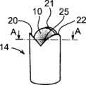
图2a示出凹形校准物体的示例。Figure 2a shows an example of a concave calibration object.
图2b示出由在图2a中所示的凹形校准物体接收的、球体形式的凸形校准物体和处于参考位置的球体。Fig. 2b shows a convex calibration object in the form of a sphere received by the concave calibration object shown in Fig. 2a and the sphere in a reference position.
图2c示出穿过在图2b中所示的球体和凹形校准物体的截面A-A。Fig. 2c shows a section A-A through the spherical and concave calibration objects shown in Fig. 2b.
图3示出在校准过程中将球体在凹形校准物体之间移动的机器人。Figure 3 shows the robot moving the sphere between the concave calibration objects during the calibration process.
图4示出凹形校准物体的另一个示例。Figure 4 shows another example of a concave calibration object.
图5为流程图,示出根据本发明的方法的示例。Fig. 5 is a flowchart illustrating an example of a method according to the invention.
具体实施方式Detailed ways
图1示出根据本发明实施方式用于确定本地坐标系Xl、Yl、Zl和机器人坐标系Xr、Yr、、Zr之间的关系的系统。在该示例中,机器人坐标系位于机器人的底座中,并且被表示为机器人的底座坐标系。在该示例中,本地坐标系为工件坐标系,并且与将由机器人加工并且由夹具3固定保持的工件2相关。FIG. 1 shows a system for determining the relationship between local coordinate systems Xl , Yl , Zl and robot coordinate systems Xr , Yr , Zr according to an embodiment of the present invention. In this example, the robot frame is located in the robot's base and is denoted as the robot's base frame. In this example, the local coordinate system is the workpiece coordinate system and relates to the
机器人1设有机器人控制器5,该机器人控制器5包括至少一个处理器、存储器和通信装置。在该示例中,机器人控制器5用来执行根据本发明的方法中的大部分步骤。机器人1包括用于附接工具8的工具法兰7。在校准过程中,以包括球体10的凸形校准物体形式的第一校准物体10固定附接在工具8上,并且因此固定附接在机器人上。采用轴或其他结构将球体10附接在机器人工具8上。在可替代的实施方式中,第一校准物体10可以附接在工具法兰7上。球体10的工具中心点(TCP)必须在机器人坐标系中是已知的。球体的TCP例如可以通过一次测量标识用于固定安装或者在每次要进行校准时采用在机器人控制器中的内置方法标识用于柔性安装。The
在该实施方式中,用于测量在三个正交方向上的力的力传感器12设在工具法兰7和工具8之间,并且因此设在校准物体10和机器人1之间。机器人编程为通过力控制而运动。这意味着机器人的运动取决于来自力传感器12的测量信号。In this embodiment,
该系统还包括安置在机器人工作范围内的三个第二校准物体14、15、16,在该情况下安置在保持工件2的夹具3上。第二校准物体14-16中的每一个为包括三个非平行倾斜表面的凹形校准物体,所述三个非平行倾斜表面布置成接收球体10,使得在球体相对于第二校准物体处于唯一限定的位置时该球体同时与所有三个表面接触。在下面,球体同时与所有三个表面接触所在的位置表示为参考位置。The system also comprises three second calibration objects 14 , 15 , 16 arranged within the working range of the robot, in this case on the
在图2a-2c中更详细示出凹形校准物体14。凹形校准物体包括三个非平行倾斜表面20、21、22。这些表面相对于管的纵向轴线的倾斜角优选在30-60°的区间内。例如,第二校准物体的上端的形状具有立方体的截头形内角的形式。凹形校准物体的一个上端形成为具有用于接收球体的开口的管,而另一个下端设计成用于将校准物体安置在夹具3上。管沿着离开开口的方向逐渐变薄。校准物体的上端具有主要为三角形的截面。管子具有三个沿着管子的纵向轴线朝着彼此倾斜的内表面20、21、22。仅在沿着管子的纵向轴线的一个位置处,此处的截面才是这些表面之间的距离对应于球体10的截面。因此,球体仅在一个唯一位置处准确地配合在管子中,在该位置球体与所有三个表面20-22接触。参考位置限定为在球体与所有三个表面接触时球体的中心点25。图2c示出在球体位于参考位置时的球体和表面。The
三个第二校准物体14、15、16优选位于本地坐标系中,以便形成三角形的角部,并且优选代表坐标转换的唯一解。机器人控制器5构造成接收和存储在球体10与第二校准物体14、15、16的所有三个表面20、21、22机械接触时机器人的位置,并且包括软件,该软件用于基于在球体与校准物体的表面接触时的机器人位置计算出本地坐标系和机器人坐标系之间的关系。The three second calibration objects 14, 15, 16 are preferably located in the local coordinate system so as to form the corners of a triangle and preferably represent a unique solution of the coordinate transformation. The
例如,第二校准物体14、15、16可以包括在夹具中作为设备的一部分。球体的位置需要在制造夹具时标识出;一次测量。第二校准物体的参考位置在本地坐标系中测量出并且存储。参考位置限定为在球体位于第二校准物体中时球体的中心点。用于第二校准物体的参考位置提前并且相对于本地坐标系确定。For example, the
该方法在寻找球体在第二校准物体中的准确位置方面必须是自动的并且精确的。对于标准机器人定位而言,这将是非常困难的。为了实现球体的自动定位,需要对机器人进行柔性并且顺应的控制。为了实现对机器人的这种柔性并且顺应的控制,可采用包括力/力矩传感器的力控制,如图1所示一样。如果在机器人设备中没有包括力控制,则可使用顺应伺服系统,以便使得机器人运动成与校准物体机械接触,但是仍然能够顺应以找到球体的精确位置。一旦球体处于在校准物体中的正确位置中,位置数据就能够在机器人控制器5内读取,并且该位置数据可与参考值一起用来计算机器人坐标系和本地坐标系之间的关系。The method must be automatic and precise in finding the exact position of the sphere in the second calibration object. This would be very difficult for standard robot localization. In order to realize the automatic positioning of the sphere, flexible and compliant control of the robot is required. To achieve such flexible and compliant control of the robot, force control including force/torque sensors can be employed, as shown in FIG. 1 . If force control is not included in the robotic device, then a compliant servo can be used in order to move the robot into mechanical contact with the calibration object, but still be able to comply to find the precise position of the sphere. Once the sphere is in the correct position in the calibration object, position data can be read within the
图3示出在校准过程中机器人将球体10在凹形校准物体14-16之间移动。在球体处于凹形校准物体的参考位置中时,读取并且存储机器人的位置。凹形校准物体的参考位置Pos 1、Pos 2和Pos 3在本地坐标系中基于夹具的初始测量值确定出。通过使用在夹具上的其中一个第二校准物体能够容易地自动或半自动标识出球体10在机器人坐标系中的坐标。机器人例如通过柔性伺服系统运动到不同的取向上以便找到精确位置。通过机器人软件中的内置算法计算出TCP。当球体的TCP已知时,容易基于测量出的机器人位置确定出在机器人坐标系中夹具上的参考位置Pos 1、2和3。在机器人坐标系中参考点的位置可以与在本地坐标系中确定出的参考位置的预定位置一起使用,以标识出机器人坐标系和本地坐标系之间的关系。Figure 3 shows the robot moving the
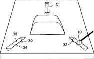
图4示出本发明的可替代实施方式。在该实施方式中,三个第二校准物体30、31、32在机器人工作范围内靠近工作物体设置。每个校准物体包括具有两个非平行倾斜表面33、34的沟槽。在该情况中,将单个定位位置信息减少至线位置信息,并且需要按照不同方式组合以生成有用的数据。一种可能的解决方案是基于每个沟槽的两个表面确定出一条线。测量在每个沟槽上的至少两个参考位置,并且计算出在这些位置之间的线。在这些表面之间的线可以用来标识工件的显著部分,并且可以容易地用来标识工件的正确坐标系。基于这两个表面的线通过球体10的两个位置测量值确定出。本地坐标系和机器人坐标系之间的关系基于所确定的线确定出。Figure 4 shows an alternative embodiment of the invention. In this embodiment, three second calibration objects 30 , 31 , 32 are arranged close to the working object within the working range of the robot. Each calibration object comprises a groove with two non-parallel inclined surfaces 33 , 34 . In this case, individual positional position information is reduced to line position information and needs to be combined in different ways to generate useful data. One possible solution is to define a line based on the two surfaces of each groove. At least two reference locations are measured on each groove, and a line between these locations is calculated. Lines between these surfaces can be used to identify significant portions of the workpiece and can easily be used to identify the correct coordinate system for the workpiece. A line based on these two surfaces is determined by two position measurements of the
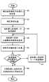
图5示出根据本发明实施方式的流程图。将理解,流程图的每个方框可以通过计算机程序指令实现。Fig. 5 shows a flowchart according to an embodiment of the present invention. It will be understood that each block of the flowchart illustrations can be implemented by computer program instructions.
在下面的示例中,由机器人承载的第一校准物体为球体,并且位于机器人的工作范围内的三个第二校准物体为在图2a-c中所示包括三个非平行倾斜表面的类型。首先,必须确定出球体相对于机器人的位置。这意味着,相对于工具坐标系确定出球体的工具中心点(TCP)。工具坐标系相对于机器人的底座坐标系是已知的。当已经确定出球体的工具中心点时,球体的TCP在机器人的底座坐标系中是已知的,方框40。通过任意已知的方法例如前面参照图3所述的方法确定出工具中心点。在校准开始之前,必须在本地坐标系中确定出所有三个校准物体的参考位置,方框42。所述位置例如使用高精度测量装置(如激光跟踪器、触摸探针或CMM)在本地坐标系中标识出。测量装置将标识出在本地坐标系中球体的中心,该球体的直径与由凹形校准物体接收的球体10的直径完全相同。优选地,提前(即在实际校准开始之前)确定出球体相对于机器人的位置和参考位置。球体和机器人之间的关系和所测量出的参考位置存储在机器人控制器中。In the example below, the first calibration object carried by the robot is a sphere and the three second calibration objects located within the working range of the robot are of the type shown in Figures 2a-c comprising three non-parallel inclined surfaces. First, the position of the sphere relative to the robot must be determined. This means that the tool center point (TCP) of the sphere is determined relative to the tool coordinate system. The tool frame is known relative to the robot's base frame. When the tool center point of the sphere has been determined, the TCP of the sphere is known in the base coordinate system of the robot, block 40 . The tool center point is determined by any known method, such as the method described above with reference to FIG. 3 . Before calibration can begin, the reference positions of all three calibration objects must be determined in the local coordinate system, block 42 . The location is identified in a local coordinate system, for example using a high precision measurement device such as a laser tracker, touch probe or CMM. The measuring device will identify the center of a sphere in the local coordinate system, the diameter of which is exactly the same as that of the
当实际校准开始时,使机器人运动到靠近其中一个凹形校准物体的位置,方框44。之后,使机器人运动,使得球体与凹形校准物体的所有校准表面接触,方框46。这例如可以如下实现:首先使机器人运动,使得球体与其中一个表面接触,然后使机器人在不松开与第一表面的接触的情况下沿着该表面运动直到该球体与下一个接触。之后,使机器人在不松开与所述表面的接触的情况下沿着两个表面运动,直到该球体与第三个表面接触。当球体与凹形校准物体的所有三个表面接触时,机器人运动停止并且当前的机器人位置存储在机器人控制器中,方框50。机器人位置为机器人的轴线的位置。对其他两个凹形校准物体重复在方框46、48和50中所述的方法步骤。当球体与校准物体的所有三个表面接触时,该球体处于参考位置,并且该机器人的位置被读取并且存储。当已经读取并存储所有三个参考位置的机器人位置时,机器人控制器计算机器人坐标系和本地坐标系之间的关系,方框56。首先,基于所测量出的机器人位置和球体相对于机器人的位置在机器人坐标系中确定出参考位置。之后,通过普通坐标转换基于在机器人坐标系中确定出的参考位置和在本地坐标系中确定出的参考位置计算出这些坐标系之间的关系。When the actual calibration begins, the robot is moved into position close to one of the concave calibration objects, block 44 . Afterwards, the robot is moved such that the sphere is in contact with all calibration surfaces of the concave calibration object, block 46 . This can be achieved, for example, by first moving the robot so that the ball comes into contact with one of the surfaces, and then moving the robot along this surface without losing contact with the first surface until the ball comes into contact with the next one. The robot is then moved along two surfaces without loosening contact with said surfaces until the sphere comes into contact with a third surface. When the sphere is in contact with all three surfaces of the concave calibration object, robot motion is stopped and the current robot position is stored in the robot controller, block 50 . The robot position is the position of the axis of the robot. The method steps described in
在该示例中,机器人坐标系为机器人的底座坐标系,并且本地坐标系为工件坐标系。机器人坐标系和本地坐标系之间的关系可以用来对机器人进行编程,以便在工件上进行加工。In this example, the robot frame is the robot's base frame, and the local frame is the workpiece frame. The relationship between the robot coordinate system and the local coordinate system can be used to program the robot to perform machining on the workpiece.
本发明不限于所公开的实施方式,而是可以在下面权利要求的范围内改变和变化。例如,第二校准物体可以包括在工件中。这将提供可能以标识出这些工件中的每一个,由此减少了对高精度夹具的需求。在可替代的实施方式中,能够在机器人工作范围内具有三个以上的第二校准物体。在可替代实施方式中,包括至少两个倾斜表面的凹形校准物体相对于机器人成固定关系附接,并且成形为球体的多个凸形校准物体安置在机器人的工作范围内。可以在外部计算机中进行该关系的计算。The invention is not limited to the disclosed embodiments but may be modified and varied within the scope of the following claims. For example, a second calibration object may be included in the workpiece. This would provide the possibility to identify each of these workpieces, thereby reducing the need for high precision fixtures. In alternative embodiments, there can be more than three second calibration objects within the working range of the robot. In an alternative embodiment, a concave calibration object comprising at least two inclined surfaces is attached in fixed relation relative to the robot, and a plurality of convex calibration objects shaped as spheres are positioned within the working range of the robot. The calculation of this relationship can be performed in an external computer.
Claims (12)
Translated fromChineseApplications Claiming Priority (1)
| Application Number | Priority Date | Filing Date | Title |
|---|---|---|---|
| PCT/EP2008/055304WO2009132703A1 (en) | 2008-04-30 | 2008-04-30 | A method and a system for determining the relation between a robot coordinate system and a local coordinate system located in the working range of the robot |
Publications (2)
| Publication Number | Publication Date |
|---|---|
| CN102015221A CN102015221A (en) | 2011-04-13 |
| CN102015221Btrue CN102015221B (en) | 2012-09-05 |
Family
ID=40340472
Family Applications (1)
| Application Number | Title | Priority Date | Filing Date |
|---|---|---|---|
| CN2008801289416AExpired - Fee RelatedCN102015221B (en) | 2008-04-30 | 2008-04-30 | A method and a system for determining the relation between a robot coordinate system and a local coordinate system located in the working range of the robot |
Country Status (5)
| Country | Link |
|---|---|
| US (1) | US7979159B2 (en) |
| EP (1) | EP2268459B9 (en) |
| CN (1) | CN102015221B (en) |
| AT (1) | ATE532610T1 (en) |
| WO (1) | WO2009132703A1 (en) |
Cited By (1)
| Publication number | Priority date | Publication date | Assignee | Title |
|---|---|---|---|---|
| US11433541B2 (en) | 2019-12-18 | 2022-09-06 | Industrial Technology Research Institute | Automated calibration system and method for a workpiece coordinate frame of a robot |
Families Citing this family (76)
| Publication number | Priority date | Publication date | Assignee | Title |
|---|---|---|---|---|
| US7784704B2 (en) | 2007-02-09 | 2010-08-31 | Harter Robert J | Self-programmable thermostat |
| JP5235376B2 (en)* | 2007-10-05 | 2013-07-10 | 川崎重工業株式会社 | Robot target position detector |
| CN102015221B (en) | 2008-04-30 | 2012-09-05 | Abb技术有限公司 | A method and a system for determining the relation between a robot coordinate system and a local coordinate system located in the working range of the robot |
| CN102802883B (en) | 2010-03-18 | 2015-07-15 | Abb研究有限公司 | Calibration of a base coordinate system for an industrial robot |
| US9393694B2 (en) | 2010-05-14 | 2016-07-19 | Cognex Corporation | System and method for robust calibration between a machine vision system and a robot |
| US9266241B2 (en) | 2011-03-14 | 2016-02-23 | Matthew E. Trompeter | Robotic work object cell calibration system |
| US9115908B2 (en) | 2011-07-27 | 2015-08-25 | Honeywell International Inc. | Systems and methods for managing a programmable thermostat |
| CN103101060B (en)* | 2011-11-11 | 2015-07-01 | 鸿富锦精密工业(深圳)有限公司 | Sensing correction method of robot tool center point |
| JP2013184236A (en)* | 2012-03-06 | 2013-09-19 | Jtekt Corp | Calibration method and calibration apparatus for robot |
| CN102679925B (en)* | 2012-05-24 | 2015-12-02 | 上海飞机制造有限公司 | Robot localization error measurement method |
| CN102818524A (en)* | 2012-07-31 | 2012-12-12 | 华南理工大学 | On-line robot parameter calibration method based on visual measurement |
| CN103659465B (en)* | 2012-09-21 | 2016-03-09 | 财团法人工业技术研究院 | compensation control method for multi-axis machine |
| JP5678979B2 (en)* | 2013-03-15 | 2015-03-04 | 株式会社安川電機 | Robot system, calibration method, and workpiece manufacturing method |
| JP2015033747A (en)* | 2013-08-09 | 2015-02-19 | 株式会社安川電機 | Robot system, robot control apparatus, and robot control method |
| DE102013014467A1 (en)* | 2013-08-30 | 2015-03-05 | Dürr Ecoclean GmbH | "Method for measuring and / or calibrating a robot" |
| JP6511715B2 (en)* | 2013-10-31 | 2019-05-15 | セイコーエプソン株式会社 | Robot control device, robot system, and robot |
| KR101438657B1 (en) | 2013-12-16 | 2014-09-12 | 주식회사일신테크 | Method of measuring industrial robot jig |
| KR102360482B1 (en) | 2014-03-17 | 2022-02-10 | 인튜어티브 서지컬 오퍼레이션즈 인코포레이티드 | Methods and devices for tele-surgical table registration |
| JP6443837B2 (en)* | 2014-09-29 | 2018-12-26 | セイコーエプソン株式会社 | Robot, robot system, control device, and control method |
| CN104589355A (en)* | 2014-11-21 | 2015-05-06 | 安徽省库仑动力自动化科技有限公司 | Method of determining absolute coordinates of robot through combination of multipoint orientation and gravity sense |
| US20160184996A1 (en)* | 2014-12-24 | 2016-06-30 | Seiko Epson Corporation | Robot, robot system, control apparatus, and control method |
| GB2536227A (en)* | 2015-03-09 | 2016-09-14 | Stratec Biomedical Ag | Pipettor Autoteaching |
| WO2016154995A1 (en) | 2015-04-02 | 2016-10-06 | Abb Technology Ltd | Method for industrial robot commissioning, industrial robot system and control system using the same |
| US9815198B2 (en)* | 2015-07-23 | 2017-11-14 | X Development Llc | System and method for determining a work offset |
| US10016892B2 (en) | 2015-07-23 | 2018-07-10 | X Development Llc | System and method for determining tool offsets |
| CN106426158A (en)* | 2015-08-11 | 2017-02-22 | 冯黎 | Automatic robot operating procedure correcting system applied in combination with three-dimensional measurement |
| CN106483963B (en)* | 2015-08-26 | 2020-02-11 | 泰科电子(上海)有限公司 | Automatic calibration method of robot system |
| CN105066831A (en)* | 2015-09-09 | 2015-11-18 | 大族激光科技产业集团股份有限公司 | Calibration method of single or multi-robot system cooperative work coordinate system |
| CN106945034B (en)* | 2016-01-07 | 2021-09-03 | 鸿富锦精密电子(郑州)有限公司 | Robot point location adjusting method and system |
| CN107214692B (en)* | 2016-03-22 | 2020-04-03 | 泰科电子(上海)有限公司 | Automatic Calibration Method of Robot System |
| CN106502208B (en)* | 2016-09-23 | 2018-04-27 | 佛山华数机器人有限公司 | A kind of industrial robot TCP scaling methods |
| CN110198812B (en)* | 2017-02-24 | 2022-02-18 | Abb瑞士股份有限公司 | Method and device for selecting an initial point for industrial robot commissioning |
| CN109304731B (en)* | 2017-07-28 | 2021-09-07 | 深圳先进技术研究院 | A robot coordinate system calibration tool |
| CN107553475B (en)* | 2017-09-11 | 2019-11-08 | 重庆华数机器人有限公司 | A kind of workpiece coordinate scaling method for work pieces process |
| JP6568172B2 (en)* | 2017-09-22 | 2019-08-28 | ファナック株式会社 | ROBOT CONTROL DEVICE, MEASUREMENT SYSTEM, AND CALIBRATION METHOD FOR CALIBRATION |
| CN108393896B (en)* | 2018-02-02 | 2021-04-09 | 山东大学 | Device and method for calibrating tool point and workpiece coordinate system of welding robot welding gun |
| EP3531062A1 (en)* | 2018-02-26 | 2019-08-28 | Renishaw PLC | Coordinate positioning machine |
| CN108742846B (en)* | 2018-04-08 | 2020-06-19 | 武汉联影智融医疗科技有限公司 | Surgical robot space coordinate system calibration device and calibration method applying same |
| WO2019235023A1 (en)* | 2018-06-04 | 2019-12-12 | 株式会社キーレックス | Teaching data creating method for articulated robot, and coordinate system detector for teaching data calibration |
| JP7088543B2 (en)* | 2018-06-12 | 2022-06-21 | 株式会社キーレックス | Teaching data calibration coordinate system detector |
| JP7190152B2 (en)* | 2018-06-04 | 2022-12-15 | 株式会社キーレックス | Teaching data creation method for articulated robots |
| TWI672206B (en)* | 2018-12-19 | 2019-09-21 | 財團法人工業技術研究院 | Method and apparatus of non-contact tool center point calibration for a mechanical arm, and a mechanical arm system with said calibration function |
| CN111360810A (en)* | 2018-12-25 | 2020-07-03 | 深圳市优必选科技有限公司 | External parameter calibration method, device, robot and storage medium of robot sensor |
| US10399227B1 (en)* | 2019-03-29 | 2019-09-03 | Mujin, Inc. | Method and control system for verifying and updating camera calibration for robot control |
| CN110142755A (en)* | 2019-03-29 | 2019-08-20 | 盐城工学院 | A six-axis robot precision calibration method |
| CN110102490B (en)* | 2019-05-23 | 2021-06-01 | 北京阿丘机器人科技有限公司 | Assembly line parcel sorting device based on vision technology and electronic equipment |
| FR3097457B1 (en)* | 2019-06-19 | 2021-07-09 | Safran Aircraft Engines | Improved aeronautical part deburring process |
| CN110202582B (en)* | 2019-07-03 | 2021-11-26 | 桂林电子科技大学 | Robot calibration method based on three-coordinate platform |
| CN110370319A (en)* | 2019-08-07 | 2019-10-25 | 江苏汇博机器人技术股份有限公司 | A kind of dual robot calibration system and method for real training |
| CN110508953A (en)* | 2019-09-23 | 2019-11-29 | 宁波奥克斯厨电制造有限公司 | A kind of positioning device and localization method of fixture for laser welding |
| CN110664484A (en)* | 2019-09-27 | 2020-01-10 | 江苏工大博实医用机器人研究发展有限公司 | Space registration method and system for robot and image equipment |
| CN110672049B (en)* | 2019-09-27 | 2021-08-24 | 江苏工大博实医用机器人研究发展有限公司 | Method and system for determining the relation between a robot coordinate system and a workpiece coordinate system |
| JP7277340B2 (en)* | 2019-11-15 | 2023-05-18 | 川崎重工業株式会社 | Master-slave system, control method and control device |
| CN110893619A (en)* | 2019-11-25 | 2020-03-20 | 上海精密计量测试研究所 | Industrial robot position appearance calibrating device based on laser tracker |
| CN110978056B (en)* | 2019-12-18 | 2021-10-22 | 东莞市沃德精密机械有限公司 | Plane calibration system and method for robot movement |
| DE102020203671B4 (en)* | 2020-03-23 | 2024-06-13 | Kuka Deutschland Gmbh | Method for controlling a robot arm |
| CN113799115B (en)* | 2020-06-11 | 2023-03-24 | 台达电子工业股份有限公司 | Coordinate correction method of robot arm |
| US11524410B2 (en) | 2020-06-12 | 2022-12-13 | Hexagon Metrology, Inc. | Robotic alignment method for workpiece measuring systems |
| CN112762822B (en)* | 2020-12-21 | 2022-05-20 | 北京无线电计量测试研究所 | Mechanical arm calibration method and system based on laser tracker |
| CN115533887A (en)* | 2021-06-30 | 2022-12-30 | 上海飞机制造有限公司 | Control method, device, equipment and storage medium |
| EP4399062A4 (en)* | 2021-09-07 | 2025-05-14 | Abb Schweiz Ag | METHOD, ELECTRONIC DEVICE, AND COMPUTER-READABLE STORAGE MEDIUM FOR CALIBRATING A ROBOT |
| CN113751934B (en)* | 2021-10-15 | 2024-05-28 | 安迅捷智能机器人(宁夏)有限责任公司 | Positioning system, welding method and welding deformation measuring method |
| CN114002243A (en)* | 2021-10-25 | 2022-02-01 | 中国科学院高能物理研究所 | Device and method for calibrating world coordinate system of CT imaging system |
| CN114055475B (en)* | 2021-12-13 | 2023-03-31 | 库卡机器人制造(上海)有限公司 | Calibration method and calibration device for robot, robot and readable storage medium |
| CN115049744B (en)* | 2022-07-11 | 2025-07-22 | 深圳市易尚展示股份有限公司 | Robot hand-eye coordinate conversion method, device, computer equipment and storage medium |
| CN115319727B (en)* | 2022-08-15 | 2024-10-29 | 中国科学院宁波材料技术与工程研究所 | Robot calibration method based on pose constraint and force perception |
| CN115338870B (en)* | 2022-09-14 | 2025-04-01 | 苏州瀚华智造智能技术有限公司 | A robot fixture calibration method for simple geometric features |
| DE102022210253A1 (en)* | 2022-09-28 | 2024-03-28 | Kuka Deutschland Gmbh | Robot arm calibration |
| CN115792869B (en)* | 2022-12-27 | 2025-02-18 | 江苏集萃智能光电系统研究所有限公司 | A joint calibration method and device for 2D area array camera and line laser 3D sensor |
| WO2024164292A1 (en)* | 2023-02-10 | 2024-08-15 | Abb Schweiz Ag | Method and device for a robot, system for calibrating or evaluating a robot and computer readable medium |
| WO2024190883A1 (en)* | 2023-03-15 | 2024-09-19 | 京セラ株式会社 | Processing device, placement member, and program |
| CN116331828B (en)* | 2023-05-11 | 2023-08-04 | 太原福莱瑞达物流设备科技有限公司 | A transport clamping jaw device for inclinometry |
| CN117045312B (en)* | 2023-08-16 | 2024-06-18 | 北京大学第三医院 | A tool head calibration and verification system and its use method |
| CN117068467B (en)* | 2023-09-11 | 2025-07-29 | 彩虹(合肥)液晶玻璃有限公司 | Glass packaging equipment and positioning detection device thereof |
| CN117310200B (en)* | 2023-11-28 | 2024-02-06 | 成都瀚辰光翼生物工程有限公司 | Pipetting point calibration method and device, pipetting control equipment and readable storage medium |
| CN118717291A (en)* | 2024-07-02 | 2024-10-01 | 上海睿触科技有限公司 | A positioning device, method, apparatus and medium for surgical operation |
Citations (4)
| Publication number | Priority date | Publication date | Assignee | Title |
|---|---|---|---|---|
| US5177563A (en)* | 1989-02-01 | 1993-01-05 | Texas A&M University System | Method and apparatus for locating physical objects |
| WO2003037575A2 (en)* | 2001-11-01 | 2003-05-08 | Assembleon N.V. | Method of calibrating a component placement machine, device suitable for carrying out such a method, and calibration component suitable for use in such a method or device |
| DE10203002A1 (en)* | 2002-01-26 | 2003-08-14 | Karmann Gmbh W | Device for calibrating industrial robot, e.g. for welding and cutting technology, uses coordinate measurement device with measurement facility supported on robot |
| CN1802240A (en)* | 2003-06-11 | 2006-07-12 | Abb公司 | A method for calibrating and programming of a robot application |
Family Cites Families (11)
| Publication number | Priority date | Publication date | Assignee | Title |
|---|---|---|---|---|
| SE501263C2 (en)* | 1991-12-10 | 1994-12-19 | Asea Brown Boveri | Method for calibrating motion shafts of an industrial robot |
| SE501867C2 (en)* | 1993-11-15 | 1995-06-12 | Asea Brown Boveri | Method and system for calibrating an industrial robot using a spherical calibration body |
| DE19602327C2 (en)* | 1996-01-24 | 1999-08-12 | Leica Geosystems Ag | Measuring ball reflector |
| US6044308A (en)* | 1997-06-13 | 2000-03-28 | Huissoon; Jan Paul | Method and device for robot tool frame calibration |
| US6070109A (en)* | 1998-03-10 | 2000-05-30 | Fanuc Robotics North America, Inc. | Robot calibration system |
| US6418774B1 (en)* | 2001-04-17 | 2002-07-16 | Abb Ab | Device and a method for calibration of an industrial robot |
| US6941192B2 (en)* | 2002-01-31 | 2005-09-06 | Abb Research Ltd. | Robot machining tool position and orientation calibration |
| US6812665B2 (en)* | 2002-04-19 | 2004-11-02 | Abb Ab | In-process relative robot workcell calibration |
| US7386365B2 (en)* | 2004-05-04 | 2008-06-10 | Intuitive Surgical, Inc. | Tool grip calibration for robotic surgery |
| US6836702B1 (en)* | 2003-06-11 | 2004-12-28 | Abb Ab | Method for fine tuning of a robot program |
| CN102015221B (en) | 2008-04-30 | 2012-09-05 | Abb技术有限公司 | A method and a system for determining the relation between a robot coordinate system and a local coordinate system located in the working range of the robot |
- 2008
- 2008-04-30CNCN2008801289416Apatent/CN102015221B/ennot_activeExpired - Fee Related
- 2008-04-30USUS12/936,520patent/US7979159B2/ennot_activeExpired - Fee Related
- 2008-04-30WOPCT/EP2008/055304patent/WO2009132703A1/enactiveApplication Filing
- 2008-04-30ATAT08749900Tpatent/ATE532610T1/enactive
- 2008-04-30EPEP08749900Apatent/EP2268459B9/ennot_activeNot-in-force
Patent Citations (4)
| Publication number | Priority date | Publication date | Assignee | Title |
|---|---|---|---|---|
| US5177563A (en)* | 1989-02-01 | 1993-01-05 | Texas A&M University System | Method and apparatus for locating physical objects |
| WO2003037575A2 (en)* | 2001-11-01 | 2003-05-08 | Assembleon N.V. | Method of calibrating a component placement machine, device suitable for carrying out such a method, and calibration component suitable for use in such a method or device |
| DE10203002A1 (en)* | 2002-01-26 | 2003-08-14 | Karmann Gmbh W | Device for calibrating industrial robot, e.g. for welding and cutting technology, uses coordinate measurement device with measurement facility supported on robot |
| CN1802240A (en)* | 2003-06-11 | 2006-07-12 | Abb公司 | A method for calibrating and programming of a robot application |
Cited By (1)
| Publication number | Priority date | Publication date | Assignee | Title |
|---|---|---|---|---|
| US11433541B2 (en) | 2019-12-18 | 2022-09-06 | Industrial Technology Research Institute | Automated calibration system and method for a workpiece coordinate frame of a robot |
Also Published As
| Publication number | Publication date |
|---|---|
| CN102015221A (en) | 2011-04-13 |
| US7979159B2 (en) | 2011-07-12 |
| EP2268459A1 (en) | 2011-01-05 |
| US20110046782A1 (en) | 2011-02-24 |
| ATE532610T1 (en) | 2011-11-15 |
| EP2268459B1 (en) | 2011-11-09 |
| WO2009132703A1 (en) | 2009-11-05 |
| EP2268459B9 (en) | 2012-03-21 |
Similar Documents
| Publication | Publication Date | Title |
|---|---|---|
| CN102015221B (en) | A method and a system for determining the relation between a robot coordinate system and a local coordinate system located in the working range of the robot | |
| US11964394B2 (en) | Coordinate positioning machine | |
| US8457786B2 (en) | Method and an apparatus for calibration of an industrial robot system | |
| US6941192B2 (en) | Robot machining tool position and orientation calibration | |
| Lembono et al. | SCALAR: Simultaneous calibration of 2-D laser and robot kinematic parameters using planarity and distance constraints | |
| CN110672049B (en) | Method and system for determining the relation between a robot coordinate system and a workpiece coordinate system | |
| KR20070042074A (en) | Parallel kinematic machine, calibration method of parallel kinematic machine, and calibration program product | |
| KR101797122B1 (en) | Method for Measurement And Compensation of Error on Portable 3D Coordinate Measurement Machine | |
| JP2013503380A (en) | Calibration method for machine tools | |
| US12418718B2 (en) | Image processing system and image processing method | |
| JP5319271B2 (en) | ROBOT TOOL POSITION DETECTING METHOD, ROBOT AND OBJECT RELATIVE POSITION DETECTING METHOD AND DEVICE | |
| WO2024164292A1 (en) | Method and device for a robot, system for calibrating or evaluating a robot and computer readable medium | |
| JP2017120216A (en) | Position measurement system and method | |
| JP5135081B2 (en) | Centering method and automatic centering system | |
| Hartmann et al. | Robot-Based Machining of Unmodeled Objects via Feature Detection in Dense Point Clouds | |
| JPS60263691A (en) | Inspection device for robot | |
| WO2024246744A1 (en) | Spatial referencing for industrial collaborative robots | |
| WO2023223763A1 (en) | Robot device and method for controlling same | |
| JP2025524182A (en) | Coordinate positioning machine | |
| JP2024145832A (en) | Friction stir welding method and friction stir welding system |
Legal Events
| Date | Code | Title | Description |
|---|---|---|---|
| C06 | Publication | ||
| PB01 | Publication | ||
| C10 | Entry into substantive examination | ||
| SE01 | Entry into force of request for substantive examination | ||
| C41 | Transfer of patent application or patent right or utility model | ||
| TA01 | Transfer of patent application right | Effective date of registration:20120531 Address after:Zurich Applicant after:ABB TECHNOLOGY Ltd. Address before:Sweden Westrm J Applicant before:ABB TECHNOLOGY Ltd. | |
| C14 | Grant of patent or utility model | ||
| GR01 | Patent grant | ||
| TR01 | Transfer of patent right | Effective date of registration:20180428 Address after:Baden, Switzerland Patentee after:ABB Switzerland Co.,Ltd. Address before:Zurich Patentee before:ABB TECHNOLOGY Ltd. | |
| TR01 | Transfer of patent right | ||
| CF01 | Termination of patent right due to non-payment of annual fee | Granted publication date:20120905 | |
| CF01 | Termination of patent right due to non-payment of annual fee |