Movatterモバイル変換


[0]ホーム

URL:


CN102014778A - Treatment system for treatment, treatment device for treatment, and treatment method for living body tissue using energy - Google Patents

Treatment system for treatment, treatment device for treatment, and treatment method for living body tissue using energy
Download PDF

Info

Publication number
CN102014778A
CN102014778ACN200880128734.0ACN200880128734ACN102014778ACN 102014778 ACN102014778 ACN 102014778ACN 200880128734 ACN200880128734 ACN 200880128734ACN 102014778 ACN102014778 ACN 102014778A
Authority
CN
China
Prior art keywords
electrode
energy
living tissue
holding
living
Prior art date
Legal status (The legal status is an assumption and is not a legal conclusion. Google has not performed a legal analysis and makes no representation as to the accuracy of the status listed.)
Granted
Application number
CN200880128734.0A
Other languages
Chinese (zh)
Other versions
CN102014778B (en
Inventor
高篠智之
饭田浩司
长濑彻
Current Assignee (The listed assignees may be inaccurate. Google has not performed a legal analysis and makes no representation or warranty as to the accuracy of the list.)
Olympus Corp
Original Assignee
Olympus Medical Systems Corp
Priority date (The priority date is an assumption and is not a legal conclusion. Google has not performed a legal analysis and makes no representation as to the accuracy of the date listed.)
Filing date
Publication date
Application filed by Olympus Medical Systems CorpfiledCriticalOlympus Medical Systems Corp
Publication of CN102014778ApublicationCriticalpatent/CN102014778A/en
Application grantedgrantedCritical
Publication of CN102014778BpublicationCriticalpatent/CN102014778B/en
Expired - Fee Relatedlegal-statusCriticalCurrent
Anticipated expirationlegal-statusCritical

Links

Images

Classifications

Landscapes

Abstract

A treatment system for applying energy to a living tissue to perform treatment, the treatment system comprising: a sealing member that, when energy is applied in a state in which a desired region between at least two living tissues is sealed, joins the sealed region; a maintaining member that maintains a state of contact between living tissues in the vicinity of the sealed region when energy is applied in a state of contacting the tissues in the vicinity of the sealed region by the sealing member; and a control unit that shifts the timing at which energy is output from the sealing member and the timing at which energy is output from the maintaining member.

Description

Translated fromChinese
治疗用处理系统、治疗用处理器具以及使用能量的生物体组织的治疗方法Treatment system for treatment, treatment device for treatment, and treatment method for living body tissue using energy

技术领域technical field

本发明涉及一种用于使用能量来治疗生物体组织的治疗处理系统以及使用能量的生物体组织的治疗方法。The present invention relates to a therapeutic treatment system for treating living tissue using energy and a method of treating living tissue using energy.

背景技术Background technique

在USP 5,443,463中公开了一种配置有多个电极的凝固钳(coagulation forceps)。该钳将来自一个电外科电源(electrosurgical power supply)的RF功率输出(RF Power Out)通过通常的无关电极连接器(indifferent electrode connector)传输给各电极。因此,该凝固钳通过被控制为相同状态的电极、利用高频能量来对生物体组织进行处理。A coagulation forceps equipped with multiple electrodes is disclosed in USP 5,443,463. The clamp transmits the RF power output (RF Power Out) from an electrosurgical power supply to each electrode through the usual indifferent electrode connector. Therefore, the coagulation forceps processes living tissue with high-frequency energy through electrodes controlled to be in the same state.

这样,由于USP 5,443,463的凝固钳的多个电极被控制为相同状态,因此例如在将电极临时分为多个组时,难以按每组来改变输出、输出定时等,从而难以使处理发生变化。即,在向各电极的能量供给方面存在优化的余地。Like this, because a plurality of electrodes of the coagulation forceps of USP 5,443,463 are controlled to be in the same state, so for example, when the electrodes are temporarily divided into a plurality of groups, it is difficult to change the output, output timing, etc. by each group, thereby making it difficult to change the process. That is, there is room for optimization in the energy supply to each electrode.

发明内容Contents of the invention

本发明的目的在于提供一种能够理想地对各电极提供能量来有效地对生物体组织进行处理的治疗处理系统、治疗用处理器具以及使用能量的生物体组织的治疗方法。An object of the present invention is to provide a therapeutic treatment system, a treatment tool for treatment, and a treatment method for living tissue using energy that can ideally supply energy to each electrode to effectively treat living tissue.

本发明所涉及的使能量作用于生物体组织来进行治疗的治疗用处理系统具备:密封部件,其在至少两个生物体组织之间的期望区域已密封的状态下使能量起作用来接合已密封的上述区域;维持部件,其在使利用上述密封部件密封的区域的附近的组织接触的状态下使能量起作用来维持已密封的上述区域附近的生物体组织之间接触的状态;以及控制部,其使从上述密封部件输出能量的定时与从上述维持部件输出能量的定时错开。According to the present invention, the treatment system for treating living tissues by applying energy to them includes: a sealing member that applies energy to join the desired region between at least two living tissues in a sealed state. The sealed region; a maintenance member that acts energy to maintain the contact state between the living tissues near the sealed region by making the tissue in the vicinity of the region sealed by the sealing member contact; and control and a portion that shifts the timing of energy output from the sealing member and the timing of energy output from the maintenance member.

本发明所涉及的使能量作用于生物体组织来进行治疗的治疗用处理系统具备:一对保持部件,其分别具有保持面,该保持面用于保持至少两个生物体组织;操作手柄,对其进行操作能够使上述保持面的至少一个相对于另一个相对地移动;第一接合部件,其被配置于上述保持面的至少一个上,在上述至少两个生物体组织之间已密封的状态下,使能量起作用来进行接合;第二接合部件,其被设置于上述第一接合部件附近,被离散地配置以维持通过上述第一接合部件而接合的生物体组织周围的生物体组织的接触并使能量起作用;以及能量输出控制部,其使从上述第一接合部件输出能量的定时与从上述第二接合部件输出能量的定时错开。According to the present invention, the treatment system for treatment by applying energy to living tissue includes: a pair of holding members respectively having holding surfaces for holding at least two living tissues; It is operable to relatively move at least one of the above-mentioned holding surfaces relative to the other; the first engagement member, which is arranged on at least one of the above-mentioned holding surfaces, is in a sealed state between the above-mentioned at least two biological tissues Next, the bonding is performed by applying energy; the second bonding member is provided near the first bonding member and is discretely arranged to maintain the biological tissue around the living tissue bonded by the first bonding member. contacting and causing energy to act; and an energy output control unit that shifts the timing of outputting energy from the first bonding member and the timing of outputting energy from the second bonding member.

本发明所涉及的使能量作用于生物体组织来进行治疗的治疗用处理系统具备:密封部件,其在使至少两个生物体组织之间的期望区域密封的状态下使能量起作用来进行接合;维持部件,其与上述密封部件形成为一体,在使上述生物体组织接触的状态下使能量起作用来维持上述生物体组织的接触;冷却部件,其被设置于上述维持部件附近,用于冷却上述维持部件;以及控制部,其对上述密封部件、上述维持部件以及上述冷却部件各自的能量输出定时进行控制。The therapeutic treatment system according to the present invention that applies energy to living tissue for treatment includes: a sealing member that applies energy to perform bonding while sealing a desired region between at least two living tissues a maintenance member, which is integrally formed with the above-mentioned sealing member, and acts on energy to maintain the contact of the above-mentioned living tissue in a state where the above-mentioned living tissue is in contact; a cooling member, which is provided near the above-mentioned maintaining member, for cooling the maintenance member; and a control unit that controls energy output timings of the sealing member, the maintenance member, and the cooling member.

本发明所涉及的使能量作用于生物体组织来进行治疗的治疗方法具备以下步骤:使至少两个生物体组织之间的期望部位密封;以及在与使上述至少两个生物体组织之间的期望部位密封的定时错开的定时,在使上述至少两个生物体组织的期望部位密封的位置附近维持使上述至少两个生物体组织接触的状态。According to the present invention, the therapeutic method of applying energy to living tissue has the following steps: sealing a desired part between at least two living tissues; The timing at which the timing of sealing the desired site is shifted is such that the contact state of the at least two living tissues is maintained near the position where the desired site of the at least two living tissues is sealed.

本发明所涉及的使能量作用于生物体组织来进行治疗的治疗用处理器具具备:密封部件,其在使至少两个生物体组织之间的期望区域密封的状态下使能量起作用来接合已密封的上述区域;以及维持部件,其与上述密封部件分开设置,在使通过上述密封部件而密封的区域的附近的组织接触的状态下与上述密封部件分开地使能量起作用来维持使已密封的上述区域附近的生物体组织之间接触的状态。According to the present invention, the treatment device for treating living tissues by applying energy to them includes: a sealing member that acts on energy to join existing tissues while sealing a desired region between at least two living tissues. the sealed region; and a maintenance member, which is provided separately from the sealing member, and maintains the seal by applying energy separately from the sealing member in a state of contacting tissue in the vicinity of the region sealed by the sealing member The state of contact between biological tissues near the above-mentioned area.

本发明所涉及的使能量作用于生物体组织来进行治疗的治疗用处理器具具备:密封部件,其在使至少两个生物体组织之间的期望区域密封的状态下使能量起作用来接合已密封的上述区域;维持部件,其与上述密封部件分开设置,在使利用上述密封部件而密封的区域的附近的组织接触的状态下与上述密封部件分开地使能量起作用来维持使已密封的上述区域的附近的生物体组织之间接触的状态;以及冷却部件,其被设置于上述维持部件附近,用于冷却上述维持部件和/或该维持部件附近区域,其中,上述密封部件的输出定时与上述维持部件以及上述冷却部件的输出定时错开。According to the present invention, the treatment device for treating living tissues by applying energy to them includes: a sealing member that acts on energy to join existing tissues while sealing a desired region between at least two living tissues. The sealed region; a maintenance member, which is provided separately from the sealing member, and maintains the sealed region by applying energy separately from the sealing member in a state of contacting tissue in the vicinity of the region sealed by the sealing member. The state of contact between the living tissues in the vicinity of the above-mentioned area; and a cooling member, which is arranged near the above-mentioned maintenance member, for cooling the above-mentioned maintenance member and/or the area near the maintenance member, wherein the output timing of the above-mentioned sealing member The output timings of the above-mentioned maintenance means and the above-mentioned cooling means are shifted.

附图说明Description of drawings

图1A是表示本发明的第一实施方式所涉及的治疗处理系统的概要图。FIG. 1A is a schematic diagram showing a medical treatment system according to the first embodiment of the present invention.

图1B是利用第一实施方式所涉及的治疗处理系统的外科用处理器具提供双极型高频能量来对生物体组织进行处理时的概要图。FIG. 1B is a schematic diagram of a case where a biological tissue is treated by supplying bipolar high-frequency energy with the surgical treatment instrument of the therapeutic treatment system according to the first embodiment.

图2A是表示第一实施方式所涉及的治疗处理系统的能量处理器具的轴、以及保持部关闭状态下的第一保持部件和第二保持部件的概要纵截面图。2A is a schematic longitudinal sectional view showing the shaft of the energy treatment device and the first holding member and the second holding member in a closed state of the holding portion of the therapeutic treatment system according to the first embodiment.

图2B是表示第一实施方式所涉及的治疗处理系统的能量处理器具的轴、以及保持部打开状态下的第一保持部件和第二保持部件的概要纵截面图。2B is a schematic longitudinal sectional view showing the shaft of the energy treatment device of the medical treatment system according to the first embodiment, and the first holding member and the second holding member in an open state of the holding portion.

图3A是表示第一实施方式所涉及的治疗处理系统的能量处理器具的保持部中的第一保持部件的接近第二保持部件一侧的概要俯视图。3A is a schematic plan view showing the side of the first holding member that is closer to the second holding member in the holding portion of the energy treatment device of the therapeutic treatment system according to the first embodiment.

图3B是表示第一实施方式所涉及的治疗处理系统的能量处理器具的保持部中的第一保持部件的沿图3A示出的3B-3B线的概要纵截面图。3B is a schematic vertical cross-sectional view taken alongline 3B-3B shown in FIG. 3A , showing the first holding member in the holding portion of the energy treatment device of the therapeutic treatment system according to the first embodiment.

图3C是表示第一实施方式所涉及的治疗处理系统的能量处理器具的保持部中的第一保持部件的沿图3A示出的3C-3C线的概要横截面图。3C is a schematic cross-sectional view taken alongline 3C-3C shown in FIG. 3A , showing the first holding member in the holding portion of the energy treatment device of the therapeutic treatment system according to the first embodiment.

图3D是表示第一实施方式所涉及的治疗处理系统的能量处理器具的保持部中的配置于第一保持部件的主体的接近第二保持部件一侧的电极的背面的概要图。3D is a schematic view showing the back surface of the electrodes disposed on the side of the main body of the first holding member on the side close to the second holding member in the holding portion of the energy treatment device of the therapeutic treatment system according to the first embodiment.

图3E是利用第一实施方式所涉及的治疗处理系统的外科用处理器具提供双极型高频能量来对生物体组织进行处理时的概要图。Fig. 3E is a schematic diagram of a case where a biological tissue is treated by supplying bipolar high-frequency energy with the surgical treatment instrument of the therapeutic treatment system according to the first embodiment.

图4是第一实施方式所涉及的治疗处理系统的概要框图。FIG. 4 is a schematic block diagram of a medical treatment system according to the first embodiment.

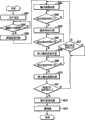
图5是使用第一实施方式所涉及的治疗处理系统对生物体组织进行使用了高频能量的处理的情况下的概要流程图。Fig. 5 is a schematic flowchart in the case of performing treatment using high-frequency energy on living tissue using the therapeutic treatment system according to the first embodiment.

图6A是表示使用第一实施方式的变形例所涉及的治疗处理系统对生物体组织进行使用了高频能量的处理的情况下的、相对于时间对生物体组织输入高频能量的输入方法的一例的概要图。FIG. 6A is a diagram illustrating an input method of high-frequency energy to living tissue with respect to time when the treatment using high-frequency energy is performed on living tissue using the medical treatment system according to a modified example of the first embodiment. A schematic diagram of an example.

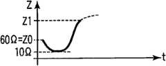
图6B是表示使用第一实施方式所涉及的治疗处理系统对生物体组织进行使用了高频能量的处理的情况下的、对生物体组织输入了规定的高频能量时的阻抗相对于时间的变化的概要图。6B is a graph showing impedance versus time when predetermined high-frequency energy is input to the living tissue when the living tissue is treated using high-frequency energy using the therapeutic treatment system according to the first embodiment. Summary graph of changes.

图6C是表示使用第一实施方式的变形例所涉及的治疗处理系统对生物体组织进行使用了高频能量的处理的情况下的、相对于时间对生物体组织输入高频能量的输入方法的一例的概要图。FIG. 6C is a diagram illustrating an input method of high-frequency energy to the living tissue with respect to time when the treatment using the high-frequency energy is performed on the living tissue using the medical treatment system according to the modified example of the first embodiment. A schematic diagram of an example.

图6D是表示使用第一实施方式的变形例所涉及的治疗处理系统对生物体组织进行使用了高频能量的处理的情况下的、相对于时间对生物体组织输入高频能量的输入方法的一例的概要图。FIG. 6D is a diagram illustrating an input method of high-frequency energy to the living tissue with respect to time when the treatment using the high-frequency energy is performed on the living tissue using the medical treatment system according to the modified example of the first embodiment. A schematic diagram of an example.

图7A是表示使小肠的两个肠道吻合的状态的概要立体图,并且是沿后述的图7C示出的7A-7A线的概要图。FIG. 7A is a schematic perspective view showing a state where two intestinal tracts of the small intestine are anastomosed, and is a schematic view alongline 7A-7A shown in FIG. 7C described later.

图7B是放大示出图7A中的以附图标记7B表示的部分的概要图。FIG. 7B is an enlarged schematic view showing a portion denoted byreference numeral 7B in FIG. 7A .

图7C是表示在使小肠的两个肠道吻合之后对这些肠道的端部进行密封的状态的概要图。FIG. 7C is a schematic diagram showing a state where the ends of the two intestinal tracts of the small intestine are sealed after anastomosis.

图7D是放大示出图7A中的以附图标记7B表示的部分的、作为图7B的变形例的概要图。FIG. 7D is a schematic diagram illustrating a modified example of FIG. 7B , showing an enlarged portion indicated byreference numeral 7B in FIG. 7A .

图8A是表示第一实施方式的第一变形例所涉及的治疗处理系统的能量处理器具的保持部中的第一保持部件的接近第二保持部件一侧的概要俯视图。8A is a schematic plan view showing the side of the first holding member close to the second holding member in the holding portion of the energy treatment instrument of the therapeutic treatment system according to the first modification of the first embodiment.

图8B是表示第一实施方式的第一变形例所涉及的治疗处理系统的能量处理器具的保持部中的第一保持部件的沿图8A示出的8B-8B线的概要横截面图。8B is a schematic cross-sectional view taken along theline 8B-8B shown in FIG. 8A , showing the first holding member in the holding portion of the energy treatment device of the therapeutic treatment system according to the first modified example of the first embodiment.

图8C是表示第一实施方式的第二变形例所涉及的治疗处理系统的能量处理器具的保持部中的第一保持部件的变形例沿图8A示出的8B-8B线的概要横截面图。8C is a schematic cross-sectional view alongline 8B-8B shown in FIG. 8A showing a modified example of the first holding member in the holding part of the energy treatment device of the therapeutic treatment system according to the second modified example of the first embodiment; .

图9A是表示第一实施方式的第三变形例所涉及的治疗处理系统的能量处理器具的保持部中的第一保持部件的接近第二保持部件一侧的概要俯视图。9A is a schematic plan view showing the side of the first holding member close to the second holding member in the holding portion of the energy treatment instrument of the therapeutic treatment system according to the third modified example of the first embodiment.

图9B是表示第一实施方式的第三变形例所涉及的治疗处理系统的能量处理器具的保持部中的第一保持部件的沿图9A示出的9B-9B线的概要横截面图。9B is a schematic cross-sectional view taken along line 9B-9B shown in FIG. 9A , showing the first holding member in the holding portion of the energy treatment device of the therapeutic treatment system according to the third modified example of the first embodiment.

图9C是表示第一实施方式的第三变形例的变形例所涉及的治疗处理系统的能量处理器具的保持部中的第一保持部件的变形例沿图9A示出的9B-9B线的概要横截面图。9C is a schematic diagram showing a modified example of the first holding member in the holding part of the energy treatment device of the therapeutic treatment system according to the modified example of the third modified example of the first embodiment along the line 9B-9B shown in FIG. 9A cross-sectional view.

图9D是表示第一实施方式的第三变形例的另一个变形例所涉及的治疗处理系统的能量处理器具的保持部中的第一保持部件的变形例沿图9A示出的9B-9B线的概要横截面图。9D shows a modified example of the first holding member in the holding part of the energy treatment device of the therapeutic treatment system according to another modified example of the third modified example of the first embodiment along the line 9B-9B shown in FIG. 9A A schematic cross-sectional view of .

图10是第一实施方式的第三变形例所涉及的治疗处理系统的概要框图。10 is a schematic block diagram of a medical treatment system according to a third modified example of the first embodiment.

图11是使用第一实施方式的第三变形例所涉及的治疗处理系统对生物体组织进行使用了高频能量的处理的情况下的概要流程图。FIG. 11 is a schematic flowchart in the case of performing treatment using high-frequency energy on living tissue using the therapeutic treatment system according to the third modification example of the first embodiment.

图12A是表示使用第一实施方式的第三变形例所涉及的治疗处理系统对生物体组织进行使用了高频能量的处理的情况下的、相对于时间对生物体组织输入高频能量的输入方法的一例的概要图。12A shows input of high-frequency energy to the living tissue with respect to time when the treatment using the high-frequency energy is performed on the living tissue using the medical treatment system according to the third modification of the first embodiment. A schematic diagram of an example of the method.

图12B是表示使用第一实施方式的第三变形例所涉及的治疗处理系统对生物体组织进行使用了高频能量的处理的情况下的、相对于时间对生物体组织输入高频能量的输入方法的一例的概要图。FIG. 12B shows the input of high-frequency energy to the living tissue with respect to time when the treatment using the high-frequency energy is performed on the living tissue using the medical treatment system according to the third modified example of the first embodiment. A schematic diagram of an example of the method.

图13A是表示第一实施方式的第四变形例所涉及的治疗处理系统的能量处理器具的保持部中的第一保持部件的接近第二保持部件一侧的概要俯视图。13A is a schematic plan view showing the side of the first holding member close to the second holding member in the holding portion of the energy treatment instrument of the medical treatment system according to the fourth modified example of the first embodiment.

图13B是表示第一实施方式的第四变形例所涉及的治疗处理系统的能量处理器具的保持部中的第一保持部件的沿图13A示出的13B-13B线的概要横截面图。13B is a schematic cross-sectional view taken alongline 13B-13B shown in FIG. 13A , showing the first holding member in the holding portion of the energy treatment device of the therapeutic treatment system according to the fourth modified example of the first embodiment.

图13C是表示第一实施方式的第四变形例所涉及的治疗处理系统的能量处理器具的保持部中的第一保持部件的变形例沿图13A示出的13C-13C线的概要横截面图。13C is a schematic cross-sectional view alongline 13C-13C shown in FIG. 13A showing a modified example of the first holding member in the holding portion of the energy treatment device of the therapeutic treatment system according to the fourth modified example of the first embodiment; .

图14是第一实施方式的第四变形例所涉及的治疗处理系统的概要框图。14 is a schematic block diagram of a medical treatment system according to a fourth modified example of the first embodiment.

图15是使用第一实施方式的第四变形例所涉及的治疗处理系统对生物体组织进行使用了高频能量的处理的情况下的概要流程图。FIG. 15 is a schematic flowchart in the case of performing treatment using high-frequency energy on living tissue using the medical treatment system according to the fourth modification example of the first embodiment.

图16是表示使用第一实施方式的第四变形例所涉及的治疗处理系统对生物体组织进行使用了高频能量的处理的情况下的、相对于时间对生物体组织输入高频能量的输入方法的一例的概要图。FIG. 16 shows the input of high-frequency energy to the living tissue with respect to time when the treatment using the high-frequency energy is performed on the living tissue using the medical treatment system according to the fourth modification of the first embodiment. A schematic diagram of an example of the method.

图17A是表示使用第一实施方式的第四变形例的变形例所涉及的治疗处理系统的能量处理器具的保持部中的第一保持部件的接近第二保持部件一侧的概要俯视图。17A is a schematic plan view showing the side of the first holding member close to the second holding member in the holding portion of the energy treatment device using the medical treatment system according to the modification of the fourth modification of the first embodiment.

图17B是表示使用第一实施方式的第四变形例的另一个变形例所涉及的治疗处理系统的能量处理器具的保持部中的第一保持部件的接近第二保持部件一侧的概要俯视图。17B is a schematic plan view showing the side of the first holding member close to the second holding member in the holding portion of the energy treatment device using the therapeutic treatment system according to another modification of the fourth modification of the first embodiment.

图18是表示第一实施方式所涉及的治疗处理系统的变形例的概要图。Fig. 18 is a schematic diagram showing a modified example of the medical treatment system according to the first embodiment.

图19是表示第二实施方式所涉及的治疗处理系统的变形例的概要图。Fig. 19 is a schematic diagram showing a modified example of the medical treatment system according to the second embodiment.

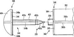
图20A是表示使第二实施方式所涉及的能量处理器具的主体侧保持部与脱离侧保持部分离的状态的概要纵截面图。20A is a schematic longitudinal sectional view showing a state in which the main body-side holding portion and the separation-side holding portion of the energy treatment device according to the second embodiment are separated.

图20B是表示使第二实施方式所涉及的能量处理器具的主体侧保持部与脱离侧保持部卡合且使脱离侧保持部与主体侧保持部隔开间隔的状态的概要纵截面图。20B is a schematic longitudinal sectional view showing a state in which the main body side holding part and the disengagement side holding part are engaged and the disengagement side holding part and the main body side holding part are spaced apart in the energy treatment instrument according to the second embodiment.

图20C是表示第二实施方式所涉及的能量处理器具的主体侧保持部的表面的概要图。20C is a schematic view showing the surface of the main body side holding part of the energy treatment device according to the second embodiment.

图21是表示使第二实施方式所涉及的能量处理器具的主体侧保持部与脱离侧保持部分离的状态的概要图。21 is a schematic diagram showing a state in which the main body side holding part and the separation side holding part of the energy treatment device according to the second embodiment are separated.

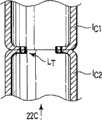
图22A是表示使用第二实施方式所涉及的能量处理器具来接合肠道之间的状态的概要图。Fig. 22A is a schematic diagram showing a state in which intestinal tracts are joined using the energy processing device according to the second embodiment.

图22B是表示使用第二实施方式所涉及的能量处理器具来接合肠道之间的状态的、沿图22A中的22B-22B线的概要纵截面图。22B is a schematic longitudinal sectional view taken along line 22B-22B in FIG. 22A , showing a state in which the intestinal tracts are joined using the energy treatment device according to the second embodiment.

图22C是表示从图22B中的箭头22C的方向观察使用第二实施方式所涉及的能量处理器具接合了肠道之间的状态的概要图。FIG. 22C is a schematic diagram showing a state in which the intestines are joined using the energy treatment device according to the second embodiment, viewed from the direction ofarrow 22C in FIG. 22B .

具体实施方式Detailed ways

下面,参照附图来说明用于实施本发明的优选方式。Next, preferred modes for implementing the present invention will be described with reference to the drawings.

[第一实施方式][first embodiment]

使用图1A至图7C来说明第一实施方式。The first embodiment will be described using FIGS. 1A to 7C .

在此,作为能量处理器具(治疗用处理器具),以用于例如通过腹壁进行处理的、直线型外科用处理器具12为例来进行说明。Here, as an energy treatment instrument (treatment treatment instrument), a linearsurgical treatment instrument 12 for performing treatment through the abdominal wall, for example, will be described as an example.

如图1A所示,治疗处理系统10具备能量处理器具12、能量源(控制部)14以及脚踏开关16。As shown in FIG. 1A , atherapeutic treatment system 10 includes anenergy treatment device 12 , an energy source (control unit) 14 , and afoot switch 16 .

能量处理器具12具备手柄22、轴24以及可打开和关闭的保持部26。手柄22通过线缆28与能量源14相连接。在能量源14上连接有脚踏开关(也可以是手柄开关)16。Theenergy treatment device 12 is provided with ahandle 22, ashaft 24, and an openable and closable holdingportion 26. Thehandle 22 is connected to theenergy source 14 by acable 28 . A foot switch (also a handle switch) 16 is connected to theenergy source 14 .

此外,脚踏开关16具备踏板16a。因此,通过由手术师操作脚踏开关16的踏板16a,能够切换从能量源14向外科用处理器具12的能量供给的打开和关闭。在按压踏板16a时,根据所设定的状态(对能量输出量、能量输出定时等进行了控制的状态)来适当地输出高频能量。当解除对踏板16a的按压时,强制地停止高频能量的输出。In addition, thefoot switch 16 includes apedal 16a. Therefore, when the pedal 16 a of thefoot switch 16 is operated by the operator, the energy supply from theenergy source 14 to thesurgical treatment instrument 12 can be switched on and off. When thepedal 16a is pressed, high-frequency energy is appropriately output in accordance with the set state (the state in which the energy output amount, the energy output timing, and the like are controlled). When the pressing of thepedal 16a is released, the output of high-frequency energy is forcibly stopped.

手柄22形成为手术师容易手握的形状,例如形成为大致L字形状。在手柄22的一端配置有轴24。从与该轴24位于相同轴上的手柄22的基端延伸出上述线缆28。Thehandle 22 is formed in a shape that can be easily held by the operator, for example, in a substantially L-shape. Ashaft 24 is arranged at one end of thehandle 22 . Theaforementioned cable 28 extends from the base end of thehandle 22 coaxially with theshaft 24 .

另一方面,手柄22的另一端侧为手术师可把持的把持部。手柄22在该另一端侧以并行设置的方式设置有保持部打开和关闭把手32。该保持部打开和关闭把手32在手柄22的大致中央部分与轴24的后述的护套44(参照图2A以及图2B)的基端相连结。当使该保持部打开和关闭把手32相对于手柄22的另一端接近和远离时,护套44沿着其轴方向移动。手柄22还以与保持部打开和关闭把手32并行设置的状态设置有用于使后述的刀具54移动刀具驱动把手34。On the other hand, the other end side of thehandle 22 is a grip portion that can be gripped by the operator. Thehandle 22 is provided with holding portion opening and closing handles 32 arranged in parallel on the other end side. The holding portion opening/closinghandle 32 is connected to the proximal end of a sheath 44 (see FIGS. 2A and 2B ), which will be described later, of theshaft 24 at a substantially central portion of thehandle 22 . When the holding portion opening and closing handle 32 is made to approach and move away from the other end of thehandle 22, thesheath 44 moves along its axial direction. Thehandle 22 is also provided with a knife drive handle 34 for moving aknife 54 described later in a state provided in parallel with a holding portion opening and closinghandle 32 .

如图2A以及图2B所示,轴24具备筒状构件42以及可滑动地配置在该筒状构件42外侧的护套44。将筒状构件42的基端部固定在手柄22上(参照图1)。护套44能够沿着筒状构件42的轴方向滑动。As shown in FIGS. 2A and 2B , theshaft 24 includes acylindrical member 42 and asheath 44 slidably arranged outside thecylindrical member 42 . The base end portion of thecylindrical member 42 is fixed to the handle 22 (see FIG. 1 ). Thesheath 44 is slidable along the axial direction of thecylindrical member 42 .

在筒状构件42外侧沿着其轴方向形成有凹部46。在该凹部46中配置有第一电极用通电线76b和第二电极用通电线78b,其中,该第一电极用通电线76b与后述的第一连续电极(输出部)76相连接,该第二电极用通电线78b与后述的第一离散电极(输出部)78相连接。虽然未图示,但是优选将第一和第二电极用通电线76b、78b配置在后述的第一和第二电极连接器76a、78a与线缆28之间,从第一和第二电极连接器76a、78a起通过第一电极用通电线76b和第二电极用通电线78b直到线缆28都集中到一起。Aconcave portion 46 is formed outside thecylindrical member 42 along the axial direction thereof. In theconcave portion 46, a firstelectrode conducting wire 76b and a secondelectrode conducting wire 78b are disposed, wherein the firstelectrode conducting wire 76b is connected to a first continuous electrode (output part) 76 described later. The 2nd electrodeelectric wire 78b is connected to the 1st discrete electrode (output part) 78 mentioned later. Although not shown, it is preferable to arrange the first and secondelectrode energizing wires 76b and 78b between the first andsecond electrode connectors 76a and 78a described later and thecable 28, so as to connect the first andsecond electrodes Connectors 76 a , 78 a pass through the firstelectrode energizing wire 76 b and the secondelectrode energizing wire 78 b until thecable 28 is gathered together.

在筒状构件42的内部穿通有第三电极用通电线86b和第四电极用通电线88b,其中,第三电极用通电线86b与后述的第二连续电极(输出部)86相连接,该第四电极用通电线88b与后述的第二离散电极(输出部)88相连接。虽然未图示,但是优选将第三和第四电极用通电线86b、88b配置在后述的第三和第四电极连接器86a、88a与线缆28之间,从第三和第四电极连接器86a、88a起直到线缆28都集中到一起。The inside of thecylindrical member 42 is penetrated with a thirdelectrode energizing wire 86b and a fourthelectrode energizing wire 88b, wherein the thirdelectrode energizing wire 86b is connected to a second continuous electrode (output part) 86 described later, This 4th electrodeelectric wire 88b is connected to the 2nd discrete electrode (output part) 88 mentioned later. Although not shown, it is preferable to arrange the third and fourthelectrode energizing wires 86 b and 88 b between the third andfourth electrode connectors 86 a and 88 a described later and thecable 28 , so that the third andfourth electrode Connectors 86a, 88a all the way up tocable 28 come together.

在轴24的筒状构件42内部沿着其轴方向可移动地配置有驱动杆52。在该驱动杆52的前端配置有薄板状的刀具(治疗辅助器具)54。因此,当操作刀具驱动把手34时,通过驱动杆52使刀具54移动。Inside thecylindrical member 42 of theshaft 24, adrive rod 52 is disposed movably along the axial direction thereof. A thin plate-shaped knife (treatment aid) 54 is arranged at the tip of thedrive rod 52 . Therefore, when the knife drive handle 34 is operated, theknife 54 is moved by thedrive rod 52 .

刀具54的前端形成有刃部54a,在基端固定有驱动杆52的前端。在该刀具54的前端与基端之间形成有长槽54b。在该长槽54b中,在与轴24的轴方向正交的方向上延伸的移动限制销56被固定在轴24的筒状构件42上。因此,刀具54的长槽54b沿着移动限制销56进行移动。因此,刀具54笔直地进行移动。此时,刀具54被配置在后述的第一保持部件62的刀具导向槽(流路、流体放出槽)62a以及第二保持部件64的刀具导向槽(流路、流体放出槽)64a中。Theblade 54a is formed at the front end of thecutter 54, and the front end of thedrive rod 52 is fixed to the base end. Along groove 54b is formed between the front end and the base end of thecutter 54 . In thislong groove 54 b , amovement restricting pin 56 extending in a direction perpendicular to the axial direction of theshaft 24 is fixed to thecylindrical member 42 of theshaft 24 . Therefore, thelong groove 54 b of thecutter 54 moves along themovement restricting pin 56 . Therefore, thecutter 54 moves straight. At this time, thecutter 54 is arranged in a cutter guide groove (flow path, fluid discharge groove) 62 a of the first holdingmember 62 and a cutter guide groove (flow path, fluid discharge groove) 64 a of the second holdingmember 64 , which will be described later.

此外,在刀具54的长槽54b的一端、另一端以及一端与另一端之间至少三个位置处卡合移动限制销56,由此形成用于控制刀具54的移动的卡合部54c。Further,movement restricting pins 56 are engaged at one end, the other end, and at least three positions between one end and the other end of thelong groove 54 b of thecutter 54 , thereby forming an engagingportion 54 c for controlling movement of thecutter 54 .

如图1A、图2A以及图2B所示,将保持部26配置于轴24的前端。如图2A以及图2B所示,保持部26具备第一保持部件(第一钳口(jaw))62和第二保持部件(第二钳口)64。As shown in FIGS. 1A , 2A and 2B , the holdingportion 26 is arranged at the tip of theshaft 24 . As shown in FIGS. 2A and 2B , the holdingunit 26 includes a first holding member (first jaw) 62 and a second holding member (second jaw) 64 .

第一保持部件62和第二保持部件64本身优选分别具有整体绝缘性。第一保持部件62一体地具备第一保持部件主体(下面主要称为主体)72以及设置于该主体72的基端部的基部74。在第一保持部件主体72和基部74中形成有引导刀具54的刀具导向槽62a。The first holdingmember 62 and the second holdingmember 64 themselves preferably each have integral insulation. The first holdingmember 62 integrally includes a first holding member main body (hereinafter mainly referred to as a main body) 72 and abase portion 74 provided at a base end portion of themain body 72 . Acutter guide groove 62 a for guiding thecutter 54 is formed in the first holding membermain body 72 and thebase 74 .

如图2A至图3C所示,在第一保持部件62的主体72中形成有多个凹部72a和保持面72b。As shown in FIGS. 2A to 3C , in themain body 72 of the first holdingmember 62 are formed a plurality ofrecesses 72 a and a holdingsurface 72 b.

并且,在主体72的多个凹部72a中配置有一个第一连续电极76和多个第一离散电极78。即,在第一保持部件62中配置有第一连续电极76和第一离散电极78作为输出部件、能量放出部。In addition, one firstcontinuous electrode 76 and a plurality of firstdiscrete electrodes 78 are disposed in the plurality ofconcave portions 72 a of themain body 72 . That is, the firstcontinuous electrode 76 and the firstdiscrete electrode 78 are arranged in the first holdingmember 62 as an output member or an energy release unit.

第一连续电极(密封部件、第一接合部件)76形成为无缝连接。第一连续电极76连续地形成为例如大致呈U字形状且在第一保持部件62的主体72的基端部具有两个端部。第一连续电极76的两个端部中的至少一个端部与配置于该一个端部上的第一电极连接器76a电连接。该第一电极连接器76a通过第一电极用通电线76b与从手柄22延伸出的线缆28相连接。并且,第一连续电极76与能量源14的后述的第一高频能量输出电路104相连接。The first continuous electrode (sealing member, first bonding member) 76 is formed so as to be seamlessly connected. The firstcontinuous electrode 76 is continuously formed in, for example, substantially U-shaped and has two end portions at the base end portion of themain body 72 of the first holdingmember 62 . At least one of the two ends of the firstcontinuous electrode 76 is electrically connected to thefirst electrode connector 76a disposed on the one end. Thefirst electrode connector 76a is connected to thecable 28 extending from thehandle 22 through the firstelectrode energizing wire 76b. Furthermore, the firstcontinuous electrode 76 is connected to a first high-frequencyenergy output circuit 104 of theenergy source 14 which will be described later.

在第一连续电极76的两个端部之间,第一保持部件62的主体72和基部74一起形成了引导刀具54的刀具导向槽(方便起见附加与第一保持部件62的刀具导向槽62a相同的附图标记62a)。Between the two ends of the firstcontinuous electrode 76, themain body 72 and thebase 74 of the first holdingmember 62 together form a cutter guide groove for guiding the cutter 54 (additional to thecutter guide groove 62a of thefirst holder member 62 for convenience) Same reference numeral 62a).

将第一离散电极(维持部件、第二接合部件)78离散地配置在第一连续电极76外侧。关于多个第一离散电极78,沿着大致U字形状的虚拟轨迹,大致等间隔地配置有相同形状的第一离散电极78。第一离散电极78例如形成为圆形状。第一离散电极78之间配置成相互大致具有规定间隔,并且各第一离散电极78被配置在相对于第一连续电极76也仅相距适当的距离的位置处。第一离散电极78的位置为以下位置:在进行处理时,允许该第一离散电极78与第二保持部件64的第二离散电极88之间的生物体组织LT由于热量而改性,但是尽可能防止第一保持部件62的第一离散电极78之间的生物体组织LT由于热量而改性,并且尽可能防止第一离散电极78与第一连续电极76之间的生物体组织由于热量而改性。The first discrete electrodes (sustaining members, second bonding members) 78 are discretely arranged outside the firstcontinuous electrodes 76 . About the some 1stdiscrete electrode 78, the 1stdiscrete electrode 78 of the same shape is arrange|positioned at substantially equal intervals along the substantially U-shaped imaginary trajectory. The firstdiscrete electrodes 78 are formed in a circular shape, for example. The firstdiscrete electrodes 78 are arranged at substantially predetermined intervals from each other, and each of the firstdiscrete electrodes 78 is also arranged at an appropriate distance from the firstcontinuous electrodes 76 . The position of the firstdiscrete electrode 78 is a position that allows the living tissueLT between the firstdiscrete electrode 78 and the second discrete electrode 88 of the second holdingmember 64 to be modified by heat during treatment, but Prevent the biological tissue LT between the firstdiscrete electrodes 78 of the first holdingmember 62 from being modified by heat as much as possible, and prevent the biological tissue between the firstdiscrete electrodes 78 and the firstcontinuous electrodes 76 from being modified by heat as much as possible. modified by heat.

虽然未图示,但是多个第一离散电极78在主体72内部相互电连接,并且与第二电极连接器78a电连接,该第二电极连接器78a与第一电极连接器76a并行地设置。该第二电极连接器78a通过第二电极用通电线78b与从手柄22延伸出的线缆28相连接。并且,第一离散电极78与能量源14的后述的第二高频能量输出电路106相连接。Although not shown, the plurality of firstdiscrete electrodes 78 are electrically connected to each other inside themain body 72 and are electrically connected to asecond electrode connector 78a provided in parallel with thefirst electrode connector 76a. Thesecond electrode connector 78a is connected to thecable 28 extending from thehandle 22 through the secondelectrode energizing wire 78b. Furthermore, the firstdiscrete electrodes 78 are connected to a second high-frequencyenergy output circuit 106 of theenergy source 14 which will be described later.

此外,第一连续电极76和第一离散电极78的表面中的保持面72b的高度形成得更高。保持面72b比第一连续电极76和第一离散电极78的表面更接近相向的第二保持部件64的主体82,与相向的第二保持部件64的主体82的保持面(方便起见附加附图标记82b)抵接。In addition, the height of the holdingsurface 72b among the surfaces of the firstcontinuous electrode 76 and the firstdiscrete electrode 78 is formed higher. The holdingsurface 72b is closer to themain body 82 of the second holdingmember 64 facing each other than the surfaces of the firstcontinuous electrode 76 and the firstdiscrete electrode 78. Mark 82b) abuts.

如图3D所示,将多个温度传感器80嵌入到第一保持部件62的主体72。在此,如图2A以及图2B所示,将多个温度传感器80配置在第一离散电极78的背面或者第一离散电极78附近。因此,能够测量与第一离散电极78接触的生物体组织LT的大概的温度T。此外,各温度传感器80与第一连续电极76的第一电极用通电线76b以及第一离散电极78的第二电极用通电线78b同样地通过温度传感器用信号线80a与后述的温度测量电路108相连接。As shown in FIG. 3D , a plurality oftemperature sensors 80 are embedded in themain body 72 of the first holdingmember 62 . Here, as shown in FIGS. 2A and 2B , a plurality oftemperature sensors 80 are arranged on the back surface of the firstdiscrete electrodes 78 or near the firstdiscrete electrodes 78 . Therefore, the approximate temperature T of the living tissueLT in contact with the firstdiscrete electrode 78 can be measured. In addition, eachtemperature sensor 80 is connected to a temperature measurement circuit described later through a temperaturesensor signal line 80 a similarly to the firstelectrode energizing wire 76 b of the firstcontinuous electrode 76 and the secondelectrode energizing wire 78 b of the firstdiscrete electrode 78 . 108 are connected.

第二保持部件64一体地具备第二保持部件主体82以及设置于该主体82的基端部的基部84。在第二保持部件主体82和基部84中形成有用于引导刀具54的刀具导向槽64a。The second holdingmember 64 integrally includes a second holding membermain body 82 and abase portion 84 provided at a base end portion of themain body 82 . Acutter guide groove 64 a for guiding thecutter 54 is formed in the second holding membermain body 82 and thebase 84 .

在第二保持部件64的主体82中形成有凹部(方便起见附加附图标记82a)和保持面82b。In themain body 82 of the second holdingmember 64 are formed a recess (to which a reference numeral 82a is attached for convenience) and a holding surface 82b.

并且,在主体82的凹部82a中配置有第二连续电极86和第二离散电极88。即,在第二保持部件64中配置有第二连续电极86和第二离散电极88作为输出部件、能量放出部。In addition, the second continuous electrode 86 and the second discrete electrode 88 are arranged in the concave portion 82 a of themain body 82 . That is, the second continuous electrode 86 and the second discrete electrode 88 are arranged in the second holdingmember 64 as an output member and an energy release unit.

与配置于第一保持部件62的第一连续电极76对称地配置第二连续电极(密封部件、第一接合部件)86。因此,在第二连续电极86的两个端部之间,第二保持部件64的主体82和基部84一起形成了引导刀具54的刀具导向槽(方便起见附加与第二保持部件64的刀具导向槽64a相同的附图标记64a)。与配置于第一保持部件62的第一离散电极78对称地配置第二离散电极88。因此,省略对第二连续电极86和第二离散电极88的详细说明。The second continuous electrode (sealing member, first bonding member) 86 is arranged symmetrically with the firstcontinuous electrode 76 arranged on the first holdingmember 62 . Therefore, between the two ends of the second continuous electrode 86, themain body 82 and thebase 84 of the second holdingmember 64 together form a knife guide groove for guiding the knife 54 (in addition to the knife guide of the second holdingmember 64 for convenience). Thegroove 64a has the same reference numeral 64a). The second discrete electrodes 88 are arranged symmetrically with the firstdiscrete electrodes 78 arranged on the first holdingmember 62 . Therefore, detailed descriptions of the second continuous electrodes 86 and the second discrete electrodes 88 are omitted.

此外,第二连续电极86与第三电极连接器86a电连接,该第三电极连接器86a被配置在与配置有第一电极连接器76a的端部相反的端部相向的端部上。另外,第三电极连接器86a通过第三电极用通电线86b与从手柄22延伸出的线缆28相连接。并且,第二连续电极86与能量源14的后述的第一高频能量输出电路104相连接。In addition, the second continuous electrode 86 is electrically connected to athird electrode connector 86a disposed at an end opposite to the end at which thefirst electrode connector 76a is disposed. In addition, thethird electrode connector 86a is connected to thecable 28 extending from thehandle 22 through the thirdelectrode energizing wire 86b. Furthermore, the second continuous electrode 86 is connected to a first high-frequencyenergy output circuit 104 of theenergy source 14 which will be described later.

第二离散电极88与第四电极连接器88a电连接,该第四电极连接器88与第三电极连接器86a并行地设置。该第四电极连接器88a通过第四电极用通电线88b与从手柄22延伸出的线缆28相连接。并且,第二离散电极88与能量源14的后述的第二高频能量输出电路106相连接。The second discrete electrode 88 is electrically connected to afourth electrode connector 88a, which is arranged in parallel with thethird electrode connector 86a. Thefourth electrode connector 88a is connected to thecable 28 extending from thehandle 22 through a fourthelectrode energizing wire 88b. Furthermore, the second discrete electrodes 88 are connected to a second high-frequencyenergy output circuit 106 of theenergy source 14 which will be described later.

此外,第一和第二保持部件62、64的刀具导向槽62a、64a形成为沿着轴24的轴方向且相互相向的状态。并且,能够利用两个刀具导向槽62a、64a来引导一个刀具54。In addition, thecutter guide grooves 62 a and 64 a of the first and second holdingmembers 62 and 64 are formed along the axial direction of theshaft 24 and face each other. Furthermore, onecutter 54 can be guided by the twocutter guide grooves 62a and 64a.

在图2A以及图2B示出的能量处理器具12的轴24的筒状构件42以及护套44上分别形成有流体放出口42a、44a,该流体放出口42a、44a放出后述的蒸汽(气体)、液体(组织液)等流体。这些流体放出口42a、44a形成于轴24的基端侧。Thecylindrical member 42 and thesheath 44 of theshaft 24 of theenergy processing device 12 shown in FIGS. 2A and 2B are respectively formed withfluid discharge ports 42a, 44a, and thefluid discharge ports 42a, 44a release steam (gas ), liquid (interstitial fluid) and other fluids. Thesefluid discharge ports 42a, 44a are formed on the base end side of theshaft 24 .

在此,虽然未图示,但是还优选在护套44的流体放出口44a的外周面设置有连接管接头。此时,后述的流体通过刀具导向槽62a、64a、轴24的筒状构件42的流体放出口42a、轴24的护套44的流体放出口44a以及连接管接头而被排出。在这种情况下,通过吸引连接管接头内能够容易地将从生物体组织LT放出的蒸汽、液体等流体从流体放出口42a、44a排出。Here, although not shown, it is also preferable to provide a connection pipe joint on the outer peripheral surface of thefluid discharge port 44 a of thesheath 44 . At this time, the fluid to be described later is discharged through thecutter guide grooves 62a, 64a, thefluid discharge port 42a of thecylindrical member 42 of theshaft 24, thefluid discharge port 44a of thesheath 44 of theshaft 24, and the connecting pipe joint. In this case, fluid such as steam and liquid released from the living tissueLT can be easily discharged from thefluid discharge ports 42a, 44a by suctioning the inside of the connection tube joint.

此外,优选将流体放出口42a、44a设置在轴24上,但是也可以不设置在轴24上而设置在手柄22上。In addition, although thefluid discharge ports 42 a and 44 a are preferably provided on theshaft 24 , they may be provided on thehandle 22 instead of theshaft 24 .

第一保持部件62的基部74被固定在轴24的筒状构件42的前端部。另一方面,通过配置在与轴24的轴方向正交的方向上的支承销92来在轴24的筒状构件42的前端部可转动地支承第二保持部件64的基部84。第二保持部件64通过支承销92的绕轴转动能够相对于第一保持部件62打开和关闭。例如利用板簧等弹性部件92a对该第二保持部件64施加力以使该第二保持部件64相对于第一保持部件62打开。Thebase portion 74 of the first holdingmember 62 is fixed to the front end portion of thecylindrical member 42 of theshaft 24 . On the other hand, thebase portion 84 of the second holdingmember 64 is rotatably supported at the front end portion of thecylindrical member 42 of theshaft 24 by asupport pin 92 disposed in a direction perpendicular to the axial direction of theshaft 24 . The second holdingmember 64 can be opened and closed relative to the first holdingmember 62 by pivoting of thesupport pin 92 . For example, the second holdingmember 64 is biased by anelastic member 92 a such as a leaf spring to open the second holdingmember 64 relative to the first holdingmember 62 .

这些第一和第二保持部件62、64的主体72、82的外表面形成为平滑的曲面形状。同样地,这些第一和第二保持部件62、64的基部74、84的外表面也形成为平滑的曲面形状。在第二保持部件64相对于第一保持部件62关闭的状态下,各保持部件62、64的主体72、82的截面形成为大致圆形或者大致椭圆形状。在第二保持部件64相对于第一保持部件62关闭的状态下,第一和第二保持部件62、64的主体72、82的保持面72b、82b相向,基部74、84形成为圆筒形状。在这种状态下,第一和第二保持部件62、64的主体72、82的基端部的直径形成为大于基部74、84的直径。并且,在主体72、82与基部74、84之间分别形成有台阶94a、94b。The outer surfaces of themain bodies 72, 82 of these first and second holdingmembers 62, 64 are formed in smooth curved shapes. Likewise, the outer surfaces of thebases 74, 84 of these first and second holdingmembers 62, 64 are also formed in smooth curved shapes. In a state where the second holdingmember 64 is closed relative to the first holdingmember 62 , themain bodies 72 , 82 of therespective holding members 62 , 64 have a substantially circular or substantially elliptical cross-section. In the state where the second holdingmember 64 is closed relative to the first holdingmember 62, the holdingsurfaces 72b, 82b of themain bodies 72, 82 of the first and second holdingmembers 62, 64 face each other, and thebase portions 74, 84 are formed in a cylindrical shape. . In this state, the diameter of the base end portion of themain body 72 , 82 of the first and second holdingmembers 62 , 64 is formed larger than the diameter of thebase portion 74 , 84 . Furthermore, steps 94a, 94b are formed between themain bodies 72, 82 and thebases 74, 84, respectively.

在此,在第二保持部件64相对于第一保持部件62关闭的状态下,将第一保持部件62和第二保持部件64的基部74、84合在一起得到的大致圆形或者大致椭圆形状的外周面形成为与筒状构件42的前端部的外周面大致相同或者直径比筒状构件42的前端部的外周面的直径稍大。因此,通过使护套44相对于筒状构件42滑动,能够以护套44的前端覆盖第一保持部件62和第二保持部件64的基部74、84。在这种状态下,如图2A所示,第一保持部件62和第二保持部件64抵抗弹性部件92a的作用力而关闭。另一方面,在以护套44的前端覆盖第一保持部件62和第二保持部件64的基部74、84的状态下使护套44向筒状构件42的基端侧滑动时,如图2B所示,由于弹性部件92a的作用力而第二保持部件64相对于第一保持部件62打开。Here, in a state where the second holdingmember 64 is closed relative to the first holdingmember 62 , a substantially circular or substantially elliptical shape obtained by combining thebases 74 , 84 of the first holdingmember 62 and the second holdingmember 64 The outer peripheral surface of thecylindrical member 42 is formed to be substantially the same as or slightly larger in diameter than the outer peripheral surface of the front end portion of thecylindrical member 42 . Therefore, by sliding thesheath 44 relative to thecylindrical member 42 , the front ends of thesheath 44 can cover thebases 74 , 84 of the first holdingmember 62 and the second holdingmember 64 . In this state, as shown in FIG. 2A, the first holdingmember 62 and the second holdingmember 64 are closed against the urging force of theelastic member 92a. On the other hand, when thesheath 44 is slid toward the base end side of thetubular member 42 with the front end of thesheath 44 covering thebases 74, 84 of the first holdingmember 62 and the second holdingmember 64, as shown in FIG. 2B As shown, the second holdingmember 64 is opened relative to the first holdingmember 62 due to the force of theelastic member 92a.

另外,在本实施方式中,第一连续电极76的基端部之间的间隔以及第二连续电极86的基端部之间的间隔大小分别形成为第一保持部件62和第二保持部件64的刀具导向槽62a、64a的宽度的程度(参照图3A),但是第一连续电极76的基端部之间的间隔以及第二连续电极86的基端部之间的间隔能够分别适当地进行设定。即,也可以在远离第一保持部件62和第二保持部件64的刀具导向槽62a、64a的边缘部的位置处设置第一连续电极76和第二连续电极86。In addition, in the present embodiment, the distance between the proximal end portions of the firstcontinuous electrodes 76 and the distance between the proximal end portions of the second continuous electrodes 86 are formed so that the first holdingmember 62 and the second holdingmember 64 are respectively large. The extent of the width of thecutter guide grooves 62a, 64a (refer to FIG. 3A ), but the interval between the base end portions of the firstcontinuous electrodes 76 and the interval between the base end portions of the second continuous electrodes 86 can be appropriately adjusted respectively. set up. That is, the firstcontinuous electrode 76 and the second continuous electrode 86 may be provided at positions away from the edge portions of thecutter guide grooves 62 a , 64 a of the first holdingmember 62 and the second holdingmember 64 .

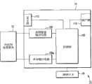
如图4所示,在能量源14的内部配置有控制部102、第一高频能量输出电路(第一控制部)104、第二高频能量输出电路(第二控制部)106、温度测量电路108、显示部110以及扬声器112。在控制部102上连接有第一高频能量输出电路104、第二高频能量输出电路106、温度测量电路108、显示部110以及扬声器112,由控制部102对它们进行控制。在控制部102上连接有脚踏开关16,当脚踏开关16被切换为接通(踏板16a被按压)时利用能量处理器具12进行处理,当被切换为断开(解除踏板16a的按压)时停止处理。显示部110作为设定单元(控制器)而发挥功能,是由控制部102对第一高频能量输出电路104和第二高频能量输出电路106的输出量(输出量本身或者进行什么处理(以接合生物体组织之间为目的的处理还是以密封生物体组织的开口为目的的处理等))以及由温度传感器80检测出的温度的显示、能量的输出定时进行控制时的设定单元。显示部110当然具有将显示部110所设定的内容(各种设定值等)进行显示的显示功能。As shown in Figure 4, in the interior ofenergy source 14,control unit 102, first high frequency energy output circuit (first control unit) 104, second high frequency energy output circuit (second control unit) 106, temperaturemeasurement A circuit 108 , adisplay unit 110 and aspeaker 112 . The first high-frequencyenergy output circuit 104 , the second high-frequencyenergy output circuit 106 , thetemperature measurement circuit 108 , thedisplay unit 110 and thespeaker 112 are connected to thecontrol unit 102 , and are controlled by thecontrol unit 102 . Afoot switch 16 is connected to thecontrol unit 102. When thefoot switch 16 is switched on (thepedal 16a is pressed), theenergy processing device 12 is used for processing, and when it is switched off (thepedal 16a is released from pressing) stop processing. Thedisplay unit 110 functions as a setting unit (controller), and the output amount (the output itself or what processing ( It is a setting unit when controlling the display of the temperature detected by thetemperature sensor 80 and the output timing of energy, such as processing for joining living tissues or processing for sealing openings of living tissues. Of course, thedisplay unit 110 has a display function for displaying the contents (various set values, etc.) set by thedisplay unit 110 .

此外,第一高频能量输出电路104通过第一和第二连续电极76、86输出高频能量,并且能够检测第一和第二连续电极76、86之间的生物体组织的阻抗Z。第二高频能量输出电路106通过第一和第二离散电极78、88输出高频能量,并且能够检测第一和第二离散电极78、88之间的生物体组织的阻抗Z。即,第一高频能量输出电路104以及第一和第二连续电极76、86具有对第一和第二连续电极76、86之间的生物体组织LT的阻抗Z进行测量的传感器功能。第二高频能量输出电路106以及第一和第二离散电极78、88具有对第一和第二离散电极78、88之间的生物体组织LT的阻抗Z进行测量的传感器功能。此外,通过温度测量电路108和温度传感器80而具有测量温度的传感器功能。In addition, the first high-frequencyenergy output circuit 104 outputs high-frequency energy through the first and secondcontinuous electrodes 76 and 86 , and can detect the impedance Z of living tissue between the first and secondcontinuous electrodes 76 and 86 . The second high-frequencyenergy output circuit 106 outputs high-frequency energy through the first and seconddiscrete electrodes 78 , 88 , and can detect the impedance Z of biological tissue between the first and seconddiscrete electrodes 78 , 88 . That is, the first high-frequencyenergy output circuit 104 and the first and secondcontinuous electrodes 76 and 86 have a sensor function for measuring the impedance Z of the living tissueLT between the first and secondcontinuous electrodes 76 and 86 . The second high-frequencyenergy output circuit 106 and the first and seconddiscrete electrodes 78 and 88 have a sensor function for measuring the impedance Z of the living tissueLT between the first and seconddiscrete electrodes 78 and 88 . In addition, thetemperature measurement circuit 108 and thetemperature sensor 80 have a sensor function for measuring temperature.

接着,说明本实施方式所涉及的治疗处理系统10的作用。Next, the operation of themedical treatment system 10 according to this embodiment will be described.

在图5中示出利用了第一高频能量输出电路104和第二高频能量输出电路106的外科用处理器具12的控制流程的一例。在图6A中示出表示来自第一高频能量输出电路104的输出和时间的关系并且表示来自第二高频能量输出电路106的输出和时间的关系的表。在图6B中示出在如图6A所示那样输入能量时通常被测量到的阻抗Z相对于时间的大概的变化。An example of the control flow of thesurgical treatment instrument 12 using the first high-frequencyenergy output circuit 104 and the second high-frequencyenergy output circuit 106 is shown in FIG. 5 . FIG. 6A shows a table showing the relationship between the output from the first high-frequencyenergy output circuit 104 and time and the relationship between the output from the second high-frequencyenergy output circuit 106 and time. FIG. 6B shows an approximate change in impedance Z with respect to time, which is usually measured when energy is input as shown in FIG. 6A .

手术师预先操作能量源14的显示部110来设定治疗处理系统10的输出条件(步骤1)。具体地说,设定来自第一高频能量输出电路104和第二高频能量输出电路106的输出(设定功率P1set[W]、P2set[W])、生物体组织LT的阻抗Z的阈值Z1、Z2以及后述的温度T的阈值T1等。The operator operates thedisplay unit 110 of theenergy source 14 in advance to set the output conditions of the therapeutic treatment system 10 (step 1). Specifically, the output from the first high-frequencyenergy output circuit 104 and the second high-frequency energy output circuit 106 (set power P1set[W], P2set[W]), the impedance Z of the living tissueLT are set. Thresholds Z1 and Z2 , and a threshold T1 of temperature T to be described later, and the like.

如图2A所示,在第二保持部件64相对于第一保持部件62关闭的状态下,例如,将外科用处理器具12的保持部26和轴24通过腹壁插入到腹腔内。使外科用处理器具12的保持部26与处理对象的生物体组织LT对峙。As shown in FIG. 2A , in a state where the second holdingmember 64 is closed relative to the first holdingmember 62 , for example, the holdingportion 26 and theshaft 24 of thesurgical treatment instrument 12 are inserted into the abdominal cavity through the abdominal wall. Theholder 26 of thesurgical treatment tool 12 is made to face the living tissueLT to be treated.

为了利用第一保持部件62和第二保持部件64来保持处理对象的生物体组织LT,操作手柄22的保持部打开和关闭把手32。此时,使护套44相对于筒状构件42向轴24的基端部侧移动。由于弹性部件92a的作用力而无法使基部74、84之间维持为筒状,从而第二保持部件64相对于第一保持部件62打开。In order to hold the living tissueLT to be treated by the first holdingmember 62 and the second holdingmember 64, the holding portion of thehandle 22 is operated to open and close thehandle 32. At this time, thesheath 44 is moved toward the proximal end side of theshaft 24 relative to thecylindrical member 42 . Since the cylindrical shape cannot be maintained between thebase parts 74 and 84 due to the biasing force of theelastic member 92 a, the second holdingmember 64 is opened relative to the first holdingmember 62 .

将处理对象的生物体组织LT配置在第一保持部件62的第一连续电极76与第二保持部件64的第二连续电极86之间以及第一保持部件62的第一离散电极78与第二保持部件64的第二离散电极88之间。在这种状态下操作手柄22的把持部打开和关闭把手32。此时,使护套44相对于筒状构件42向轴24的前端部侧移动。通过护套44来抵抗弹性部件92a的作用力,使基部74、84之间关闭而成为筒状。因此,与基部74形成为一体的第一保持部件62的主体72和与基部84形成为一体的第二保持部件64的主体82关闭。即,第二保持部件64相对于第一保持部件62关闭。这样,将处理对象的生物体组织LT把持在第一保持部件62与第二保持部件64之间。The biological tissue LT to be treated is disposed between the firstcontinuous electrode 76 of the first holdingmember 62 and the second continuous electrode 86 of the second holdingmember 64, and between the firstdiscrete electrodes 78 of the first holdingmember 62 and the second continuous electrode 86 of the first holdingmember 62. between the second discrete electrodes 88 of the two holdingmembers 64 . In this state, the grip portion of thehandle 22 is operated to open and close thehandle 32 . At this time, thesheath 44 is moved toward the front end side of theshaft 24 relative to thecylindrical member 42 . The biasing force of theelastic member 92a is resisted by thesheath 44, and the space between thebase parts 74 and 84 is closed to form a cylindrical shape. Thus, themain body 72 of the first holdingmember 62 integrally formed with thebase 74 and themain body 82 of the second holdingmember 64 integrally formed with the base 84 are closed. That is, the second holdingmember 64 is closed relative to the first holdingmember 62 . In this way, the living tissueLT to be treated is held between the first holdingmember 62 and the second holdingmember 64 .

此时,处理对象的生物体组织LT与第一保持部件62的第一连续电极76以及第二保持部件64的第二连续电极86两者接触。处理对象的生物体组织LT与第一保持部件62的第一离散电极78以及第二保持部件64的第二离散电极88两者接触。处理对象的生物体组织LT的周围组织与第一保持部件62的保持面72b中的边缘部和第二保持部件64的保持面82b中的边缘部(未图示)相向的接触面两者紧密接合。At this time, the living tissueLT to be treated is in contact with both the firstcontinuous electrode 76 of the first holdingmember 62 and the second continuous electrode 86 of the second holdingmember 64 . The living tissueLT to be treated is in contact with both the firstdiscrete electrodes 78 of the first holdingmember 62 and the second discrete electrodes 88 of the second holdingmember 64 . Both the contact surfaces of the peripheral tissue of the living tissueLT to be treated and the edge portion of the holdingsurface 72b of the first holdingmember 62 and the edge portion (not shown) of the holding surface 82b of the second holdingmember 64 face Tight joint.

这样,在第一保持部件62与第二保持部件64之间把持生物体组织的状态下,操作脚踏开关16的踏板16a。能量源14的控制部102判断开关16的踏板16a是否通过手术师的操作被按压而切换为接通(步骤2)。In this way, the pedal 16 a of thefoot switch 16 is operated while the living tissue is gripped between the first holdingmember 62 and the second holdingmember 64 . Thecontrol unit 102 of theenergy source 14 judges whether or not the pedal 16a of theswitch 16 is pressed and switched on by the operator's operation (step 2).

在判断为开关16的踏板16a被按压而切换为接通时,从能量源14的第一高频能量输出电路104向第一连续电极76和第二连续电极86之间的生物体组织(第一区域的生物体组织)LT提供高频能量(步骤3)。When it is determined that the pedal 16a of theswitch 16 is pressed and switched on, the first high-frequencyenergy output circuit 104 of theenergy source 14 supplies the living tissue between the firstcontinuous electrode 76 and the second continuous electrode 86 (the second continuous electrode 86 ). A region of biological tissue) LT provides high-frequency energy (step 3).

并且,第一高频能量输出电路104对第一保持部件62的第一连续电极76和第二保持部件64的第二连续电极86之间提供利用显示部110预先设定的设定功率P1set[W]、例如20[W]~80[W]左右的电力。And, the first high-frequencyenergy output circuit 104 provides the preset power P1set [ W], for example, about 20 [W] to 80 [W].

因此,第一高频能量输出电路104对第一保持部件62的第一连续电极76与第二保持部件64的第二连续电极86之间的处理对象的生物体组织LT通高频电流。即,对被把持在电极76、86之间的生物体组织LT提供高频能量。因此,使被把持在电极76、86之间的生物体组织LT内产生焦耳热来对生物体组织LT本身加热。由于焦耳热的作用而被把持在电极76、86之间的生物体组织LT内的细胞膜被破坏,放出细胞膜内物质,与以胶原蛋白为代表的细胞外成分均匀化。由于高频电流流入电极76、86之间的生物体组织LT,因此焦耳热进一步作用于这样均匀化的组织LT,例如对生物体组织LT的接合面之间进行接合,对组织的层间之间进行接合。因而,当对电极76、86之间通高频电流时,生物体组织LT本身发热而脱水,并且生物体组织LT内部被改性(生物体组织LT被烧灼)。因此,通过第一连续电极76和第二连续电极86而生物体组织LT被连续地(大致U字形状的状态)改性。Therefore, the first high-frequencyenergy output circuit 104 supplies high-frequency current to the biological tissue LT to be treated between the firstcontinuous electrode 76 of the first holdingmember 62 and the second continuous electrode 86 of the second holdingmember 64 . That is, high-frequency energy is supplied to the living tissueLT held between theelectrodes 76 and 86 . Therefore, Joule heat is generated in the living tissueLT held between theelectrodes 76 and 86 to heat the living tissueLT itself. The cell membrane in the living tissueLT held between theelectrodes 76 and 86 is destroyed due to the action of Joule heat, and the substances in the cell membrane are released to be homogenized with extracellular components represented by collagen. Since high-frequency current flows into the livingtissueLT between theelectrodes 76 and 86, Joule heat further acts on the thus homogenized tissueLT . bonding between layers. Therefore, when a high-frequency current is passed between thecounter electrodes 76 and 86, the living tissueLT itself generates heat and dehydrates, and the inside of the living tissueLT is modified (the living tissueLT is cauterized). Therefore, the living tissueLT is continuously (approximately U-shaped) modified by the firstcontinuous electrode 76 and the second continuous electrode 86 .

此时,由第一高频能量输出电路104通过第一连续电极76和第二连续电极86来测量所把持的生物体组织LT的阻抗Z。如图6B所示,开始进行处理时的阻抗Z0例如为60[Ω]左右。并且,随着高频电流流入到生物体组织LT而生物体组织LT被烧灼,阻抗Z的值上升。At this time, the impedance Z of the grasped living tissueLT is measured by the first high-frequencyenergy output circuit 104 through the firstcontinuous electrode 76 and the second continuous electrode 86 . As shown in FIG. 6B , the impedance Z0 at the start of processing is, for example, about 60 [Ω]. And, as the high-frequency current flows into the living tissueLT to burn the living tissueLT , the value of the impedance Z increases.

这样,随着生物体组织LT被烧灼,从生物体组织LT放出流体(例如液体(血液)和/或气体(水蒸气))。此时,与第一连续电极76和第二连续电极86与生物体组织LT的紧密接合程度相比,第一保持部件62的保持面72b和第二保持部件64的保持面82b与生物体组织LT更加紧密接合。因此,保持面72b、82b作为抑制流体向第一保持部件62和第二保持部件64外侧流出的障壁部(dam)而发挥功能。因而,使从生物体组织LT放出的流体流入到第一连续电极76内侧的刀具导向槽62a以及第二连续电极86内侧的刀具导向槽64a,例如通过吸引来使从生物体组织LT放出的流体从第一保持部件62和第二保持部件64流到轴24。在从生物体组织LT放出流体的期间,使该流体持续流入到刀具导向槽62a、64a。因此,防止在温度上升的状态下从生物体组织LT放出的流体产生热传播(thermal spread),能够防止对不是处理对象的部分带来影响。In this way, as the living tissueLT is cauterized, fluid (such as liquid (blood) and/or gas (steam)) is released from the living tissueLT . At this time, the holdingsurface 72b of the first holdingmember 62 and the holding surface 82b of the second holdingmember 64 are in contact with the living body tissueLT compared to the degree of close contact between the firstcontinuous electrode 76 and the second continuous electrode 86 and the living tissue LT. TissueLT is more tightly knit. Therefore, the holding surfaces 72 b and 82 b function as barriers (dams) that suppress the outflow of the fluid to the outside of the first holdingmember 62 and the second holdingmember 64 . Therefore, the fluid released from the living tissueLT flows into theknife guide groove 62a inside the firstcontinuous electrode 76 and theknife guide groove 64a inside the second continuous electrode 86, for example, by suction to release the fluid from the living tissueLT . The fluid flows from the first retainingmember 62 and the second retainingmember 64 to theshaft 24 . While the fluid is discharged from the living tissueLT , the fluid continues to flow into thecutter guide grooves 62a, 64a. Therefore, it is possible to prevent thermal spread of the fluid released from the living tissueLT in a state where the temperature is raised, and to prevent the influence on the part that is not the treatment target.

接着,控制部102判断根据来自第一高频能量输出电路104的信号而计算出的高频能量输出时的阻抗Z是否大于等于预先利用显示部110设定(步骤1)的阈值Z1(如图6B所示,在此大约为1000[Ω])(步骤4)。阈值Z1例如位于已知的阻抗Z的值的上升率变慢的位置。并且,在判断为阻抗Z小于阈值Z1的情况下,处理返回到步骤3。即,继续对被把持在第一保持部件62的第一连续电极76和第二保持部件64的第二连续电极86之间的生物体组织LT提供用于进行处理的高频能量。Next, thecontrol unit 102 judges whether the impedance Z during the high-frequency energy output calculated from the signal from the first high-frequencyenergy output circuit 104 is greater than or equal to the threshold value Z1 (as shown in FIG. 6B, it is about 1000 [Ω] here) (step 4). Threshold Z1 is located, for example, at a position where the rise rate of the known impedance Z value becomes slow. And, when it is judged that the impedance Z is smaller than the threshold value Z1, the process returns to step 3 . That is, the living tissue LT held between the firstcontinuous electrode 76 of the first holdingmember 62 and the second continuous electrode 86 of the second holding member64 continues to be supplied with high-frequency energy for treatment.

在判断为阻抗Z大于阈值Z1的情况下,从控制部102向第一高频能量输出电路104传输信号。并且,停止从第一高频能量输出电路104向第一连续电极76和第二连续电极86的输出(步骤5)。When it is determined that the impedance Z is greater than the threshold value Z1 , a signal is transmitted from thecontrol unit 102 to the first high-frequencyenergy output circuit 104 . And the output from the 1st high-frequencyenergy output circuit 104 to the 1stcontinuous electrode 76 and the 2nd continuous electrode 86 is stopped (step 5).

接着,从能量源14的第二高频能量输出电路106向第一离散电极78和第二离散电极88之间的生物体组织(第二区域的生物体组织)LT提供能量(步骤6)。即,与从第一高频能量输出电路104向第一连续电极76和第二连续电极86的生物体组织LT提供能量的时间错开(输出定时偏移的状态)地,从第二高频能量输出电路106向第一离散电极78和第二离散电极88之间的生物体组织LT提供能量。Then, from the second high-frequencyenergy output circuit 106 of theenergy source 14, energy is provided to the biological tissue (the biological tissue in the second region) LT between the firstdiscrete electrode 78 and the second discrete electrode 88 (step 6) . That is, from the first high-frequencyenergy output circuit 104 to the living tissueLT of the firstcontinuous electrode 76 and the second continuous electrode 86, the energy is staggered (the output timing is shifted), and the energy from the second high-frequencyenergy output circuit 104 Theenergy output circuit 106 provides energy to the biological tissueLT between the firstdiscrete electrode 78 and the second discrete electrode 88 .

并且,第二高频能量输出电路106对第一保持部件62的第一离散电极78和第二保持部件64的第二离散电极88之间提供利用显示部110预先设定的设定功率P2set[W]、例如20[W]~80[W]左右的电力。此外,从第二高频能量输出电路106向第一离散电极78和第二离散电极88的输出可以大于从第一高频能量输出电路104向第一连续电极76和第二连续电极86的输出,也可以小于从第一高频能量输出电路104向第一连续电极76和第二连续电极86的输出。在处理之前根据处理对象、目的等来适当地设定这种输出的大小(步骤1)。And, the second high-frequencyenergy output circuit 106 provides preset power P2set[ W], for example, about 20 [W] to 80 [W]. In addition, the output from the second high-frequencyenergy output circuit 106 to the firstdiscrete electrode 78 and the second discrete electrode 88 may be greater than the output from the first high-frequencyenergy output circuit 104 to the firstcontinuous electrode 76 and the second continuous electrode 86 , may also be smaller than the output from the first high-frequencyenergy output circuit 104 to the firstcontinuous electrode 76 and the second continuous electrode 86 . The size of such an output is appropriately set according to the processing object, purpose, etc. before processing (step 1).

因此,高频电流流过被把持在第一保持部件62和第二保持部件64之间的生物体组织LT,通过焦耳热的作用使生物体组织LT发热并开始组织的烧灼(组织的改性)。于是,通过第一离散电极78和第二离散电极88而使这些离散电极78、88之间的生物体组织LT被离散地改性。此时,由第二高频能量输出电路106通过第一离散电极78和第二离散电极88来测量所把持的生物体组织LT的阻抗Z。关于开始进行处理时的阻抗Z,由于生物体组织LT没有改性,因此能够将图6B中的阈值Z1替换为阈值Z2,初始阻抗Z例如为Z0。并且,随着高频电流流过生物体组织LT而生物体组织LT被烧灼,阻抗Z的值上升。Therefore, the high-frequency current flows through the living tissueLT held between the first holdingmember 62 and the second holdingmember 64, and the living tissueLT is heated by the action of Joule heat to start cauterization of the tissue (tissue ablation). modified). Then, the living tissueLT between thesediscrete electrodes 78 and 88 is discretely modified by the firstdiscrete electrode 78 and the second discrete electrode 88 . At this time, the impedance Z of the held biological tissueLT is measured by the second high-frequencyenergy output circuit 106 through the firstdiscrete electrode 78 and the second discrete electrode 88 . Regarding the impedance Z at the start of the treatment, since the living tissueLT is not modified, the threshold Z1 in FIG. 6B can be replaced with the threshold Z2, and the initial impedance Z is, for example, Z0. And, as the high-frequency current flows through the living tissueLT to burn the living tissueLT , the value of the impedance Z increases.

并且,在开始从第二高频能量输出电路106进行输出之后,优选在从第一高频能量输出电路104完成输出时起,通过被嵌入到第一保持部件62的主体72的温度传感器80来持续测量与第一离散电极78抵接的生物体组织LT附近的温度T。并且,判断温度T是否达到规定温度T1(步骤7)。如果达到温度T1,则停止向第二高频能量输出电路106的输出(步骤8)。等待与第一离散电极78抵接的生物体组织LT附近的温度T下降到低于温度T1。如果判断为温度T下降到低于设定温度T1(步骤9),则再次对第二高频能量输出电路106提供能量(步骤10)。这样,将温度T1作为阈值,自动切换来自第二高频能量输出电路106的能量供给的打开和关闭。And, after starting to output from the second high-frequencyenergy output circuit 106, preferably when the output from the first high-frequencyenergy output circuit 104 is completed, thetemperature sensor 80 embedded in themain body 72 of the first holdingmember 62 The temperature T near the living tissueLT in contact with the firstdiscrete electrode 78 is continuously measured. Then, it is judged whether or not the temperature T has reached a predetermined temperature T1 (step 7). When the temperature T1 is reached, the output to the second high-frequencyenergy output circuit 106 is stopped (step 8). Waiting for the temperature T near the living tissueLT in contact with the firstdiscrete electrode 78 to drop below the temperature T1. If it is determined that the temperature T has dropped below the set temperature T1 (step 9), energy is supplied to the second high-frequencyenergy output circuit 106 again (step 10). In this way, using the temperature T1 as a threshold value, the energy supply from the second high-frequencyenergy output circuit 106 is automatically switched on and off.

然后,随着生物体组织LT被烧灼,从生物体组织LT放出流体(例如液体(血液)和/或气体(水蒸气))。此时,与第一离散电极78和第二离散电极88与生物体组织LT的紧密接合程度相比,第一保持部件62的保持面72b和第二保持部件64的保持面82b与生物体组织LT的紧密接合程度高。因此,保持面72b、82b作为抑制流体向第一保持部件62和第二保持部件64外侧流出的障壁部(dam)而发挥功能。因而,使从生物体组织LT放出的流体流入到比第一离散电极78内侧的第一连续电极76更内侧以及比第二离散电极88内侧的第二连续电极86更内侧的刀具导向槽62a、64a,例如通过吸引来使从生物体组织LT放出的流体从第一和第二保持部件62、64流入到轴24。在从生物体组织LT放出流体的期间,使该流体持续流入到刀具导向槽62a、64a。因此,防止在温度上升的状态下从生物体组织LT放出的流体产生热传播,能够防止对不是处理对象的部分带来影响。此时,从第一高频能量输出电路104进行输出的定时与从第二高频能量输出电路106进行输出的定时错开,因此能够在防止相互干扰的状态下,使流体流入到刀具导向槽62a、64a。Then, as the living tissueLT is cauterized, fluid (for example, liquid (blood) and/or gas (steam)) is released from the living tissueLT . At this time, the holdingsurface 72b of the first holdingmember 62 and the holding surface 82b of the second holdingmember 64 are in contact with the living body tissueLT compared to the degree of close contact between the firstdiscrete electrode 78 and the second discrete electrode 88 and the living tissue LT. TissueLT has a high degree of tight junction. Therefore, the holding surfaces 72 b and 82 b function as barriers (dams) that suppress the outflow of the fluid to the outside of the first holdingmember 62 and the second holdingmember 64 . Therefore, the fluid released from the living tissueLT flows into thecutter guide groove 62a inside the firstcontinuous electrode 76 inside the firstdiscrete electrode 78 and inside the second continuous electrode 86 inside the second discrete electrode 88. , 64a, the fluid discharged from the living tissueLT flows into theshaft 24 from the first and second holdingmembers 62, 64, for example, by suction. While the fluid is discharged from the living tissueLT , the fluid continues to flow into thecutter guide grooves 62a, 64a. Therefore, it is possible to prevent heat propagation of the fluid discharged from the living tissueLT in a state where the temperature is raised, and to prevent influence on parts not to be treated. At this time, the timing of outputting from the first high-frequencyenergy output circuit 104 and the timing of outputting from the second high-frequencyenergy outputting circuit 106 are shifted, so that the fluid can flow into thecutter guide groove 62a while preventing mutual interference. , 64a.

接着,控制部102判断根据来自第二高频能量输出电路106的信号而计算出的高频能量输出时的阻抗Z是否大于等于预先设定的阈值Z2(如图6B所示,在此大约为1000[Ω])(步骤11)。优选将阈值Z2设定于已知的阻抗Z的值的上升率变慢的位置。并且,在判断为阻抗Z小于阈值Z2的情况下,处理返回到步骤6。即,根据温度T1切换打开和关闭,并且对被把持在第一保持部件62的第一离散电极78和第二保持部件64的第二离散电极88之间的生物体组织LT提供用于进行处理的高频能量。Next, thecontrol unit 102 judges whether the impedance Z during the high-frequency energy output calculated according to the signal from the second high-frequencyenergy output circuit 106 is greater than or equal to a preset threshold value Z2 (as shown in FIG. 6B , here approximately 1000[Ω]) (step 11). It is preferable to set the threshold Z2 at a position where the rate of rise of the value of the known impedance Z becomes slow. And, when it is determined that the impedance Z is smaller than the threshold Z2, the process returns to step 6 . That is, it is switched on and off according to the temperature T1, and the living tissueLT held between the firstdiscrete electrodes 78 of the first holdingmember 62 and the second discrete electrodes 88 of the second holdingmember 64 is supplied for performing Processed high frequency energy.

在判断为阻抗Z大于阈值Z2的情况下,从控制部102对第二高频能量输出电路106传输信号。并且,停止从第二高频能量输出电路106向第一离散电极78和第二离散电极88的输出(步骤12)。When it is determined that the impedance Z is larger than the threshold value Z2 , a signal is transmitted from thecontrol unit 102 to the second high-frequencyenergy output circuit 106 . And the output to the 1stdiscrete electrode 78 and the 2nd discrete electrode 88 from the 2nd high-frequencyenergy output circuit 106 is stopped (step 12).

然后,在停止输出之后,控制部102从扬声器112发出蜂鸣声(步骤13)。这样,能够容易地认识到从第二高频能量输出电路106通过第一离散电极78和第二离散电极88对生物体组织LT进行的处理已结束。Then, after stopping the output, thecontrol unit 102 emits a buzzer sound from the speaker 112 (step 13). In this way, it can be easily recognized that the treatment of the living tissueLT by the second high-frequencyenergy output circuit 106 through the firstdiscrete electrode 78 and the second discrete electrode 88 has been completed.

此外,在保持按压下脚踏开关16的踏板16a的状态下,处理从图5示出的“开始”进行到“结束”为止,但是当在“开始”至“结束”之间解除对踏板16a的按压时,控制部102在解除对该踏板16a的按压的时刻强制地停止处理。即,当解除对踏板16a的按压时,控制部102停止第一高频能量输出电路104和第二高频能量输出电路106中的任一个电路的输出。In addition, under the state of keeping pressing the pedal 16a of thefoot switch 16, the processing proceeds from "start" shown in Fig. 5 to "end", but when thepedal 16a is released between "start" and "end", When thepedal 16a is pressed, thecontrol unit 102 forcibly stops the process when thepedal 16a is released from the press. That is, when the pressing of thepedal 16a is released, thecontrol unit 102 stops the output of any one of the first high-frequencyenergy output circuit 104 and the second high-frequencyenergy output circuit 106 .

在此,对如下情况进行说明:使用具有这种作用的治疗处理系统10来如图7A至图7C所示那样,例如使小肠的并行设置的肠道IC1、IC2之间接合并密封所接合的肠道IC1、IC2之间。Here, a case will be described where using thetherapeutic treatment system 10 having such a function, as shown in FIGS. 7A to 7C , for example, the intestinal tracts IC1 and IC2 arranged in parallel in the small intestine are joined and sealed. Between IC1 and IC2 of the intestinal tract.

操作能量源14的显示部110来预先设定来自第一高频能量输出电路104和第二高频能量输出电路106的输出。此时,预定首先对并行设置的一对肠道IC1、IC2之间进行接合,因此将来自第二高频能量输出电路106的输出适当地设定得较高。The outputs from the first high-frequencyenergy output circuit 104 and the second high-frequencyenergy output circuit 106 are set in advance by operating thedisplay unit 110 of theenergy source 14 . At this time, since the connection between the pair of intestinal tracts IC1 and IC2 arranged in parallel is to be performed first, the output from the second high-frequencyenergy output circuit 106 is appropriately set high.

利用第一保持部件62的保持面72b和第二保持部件64的保持面82b,以夹持两个肠道IC1、IC2的壁面的方式保持并行设置状态的一对肠道IC1、IC2The pair of intestinal tracts IC1 , I C2 arranged in parallel are held by the holdingsurface 72 b of the first holdingmember 62 and the holding surface 82 b of the second holdingmember 64 so as to sandwich the wall surfaces of the two intestinal tracts IC1 , IC2 .C2 .

在这种状态下,当按压脚踏开关16的踏板16a时,对第一连续电极76和第二连续电极86之间的生物体组织LT提供能量。因此,由第一连续电极76和第二连续电极86对肠道IC1、IC2之间进行加热而使肠道IC1、IC2改性。In this state, when the pedal 16 a of thefoot switch 16 is pressed, energy is supplied to the living tissueLT between the firstcontinuous electrode 76 and the second continuous electrode 86 . Therefore, the intestinal tracts IC1 and IC2 are modified by heating between the intestinal tracts I C1 and I C2bythe firstcontinuous electrode 76 and the second continuous electrode 86 .

并且,在第一连续电极76和第二连续电极86之间的生物体组织LT达到规定的阈值Z1时,停止从第一高频能量输出电路104输出能量。Then, when the living tissueLT between the firstcontinuous electrode 76 and the second continuous electrode 86 reaches the predetermined threshold Z1, the energy output from the first high-frequencyenergy output circuit 104 is stopped.

之后,对第一离散电极78和第二离散电极88之间的生物体组织LT提供能量。因此,由第一离散电极78和第二离散电极88对肠道IC1、IC2之间进行加热而使肠道IC1、IC2改性。After that, energy is supplied to the living tissueLT between the firstdiscrete electrode 78 and the second discrete electrode 88 . Therefore, the intestinal tracts IC1 , IC2 are modified by heating between the intestinal tracts IC1 , IC2 by the firstdiscrete electrode 78 and the second discrete electrode 88 .

并且,在温度T到达规定的温度T1时,自动地停止输出(关闭),在下降到低于温度T1时自动地输出(打开),反复进行这些输出的打开和关闭,并且在第一离散电极78和第二离散电极88之间的生物体组织的阻抗Z达到规定的阈值Z2时完全停止来自第二高频能量输出电路106的输出。And, when the temperature T reaches the specified temperature T1, the output is automatically stopped (closed), and when it falls below the temperature T1, the output is automatically turned on (open), and the opening and closing of these outputs are repeated, and at the first discrete electrode When the impedance Z of the living tissue between 78 and the second discrete electrode 88 reaches a predetermined threshold Z2, the output from the second high-frequencyenergy output circuit 106 is completely stopped.

此外,在第一连续电极76和第二连续电极86之间的生物体组织LT的阻抗Z达到规定的阈值Z1时,由第一连续电极76和第二连续电极86对肠道IC1、IC2之间进行加热而使肠道IC1、IC2改性接合。在第一离散电极78与第二离散电极88之间的生物体组织LT的阻抗Z达到规定的阈值Z2时,由第一离散电极78和第二离散电极88对肠道IC1、IC2之间进行加热而使肠道IC1、IC2改性接合。这样,肠道IC1、IC2之间被连续地以及离散地改性接合(吻合)。In addition, when the impedance Z of the living tissueLT between the firstcontinuous electrode 76 and the second continuous electrode 86 reaches a predetermined threshold value Z1, the intestinal tract IC1 , IC2 is heated to modify and join the intestines IC1 and IC2 . When the impedance Z of the biological tissueLT between the firstdiscrete electrode 78 and the second discrete electrode 88 reaches the prescribed threshold Z2, the intestinal tract IC1 and IC2 are controlled by the firstdiscrete electrode 78 and the second discrete electrode 88 Heat between them to make the intestinal IC1 and IC2 modified and joined. In this way, the joints (anastomoses) between the intestinal tracts IC1 and IC2 are modified continuously and discretely.

并且,在肠道IC1、IC2之间被把持在第一保持部件62与第二保持部件64之间的状态下,操作图1A示出的刀具驱动把手34,使刀具54从图2A以及图2B示出的状态沿着刀具导向槽62a、64a前进。随着刀具54前进,其前端的刃部54a切断通过第一连续电极76和第二连续电极86而被改性接合部位的内侧。并且,刀具54切断通过第一连续电极76和第二连续电极86而被改性为大致U字型的部位的内侧直到U字型的前端部附近为止。因此,如图7A所示,肠道IC1、IC2的壁面的被密封为大致U字形状之间的部位被切断而肠道IC1、IC2的壁面之间连通。And, in the state between the intestines IC1 , IC2 being grasped between the first holdingmember 62 and the second holdingmember 64, theknife driving handle 34 shown in FIG. 1A is operated to make theknife 54 move from FIG. 2A and The state shown in FIG. 2B advances along thecutter guide grooves 62a, 64a. As thecutter 54 advances, thecutting edge portion 54 a at the tip cuts the inside of the joint modified by the firstcontinuous electrode 76 and the second continuous electrode 86 . Then, thecutter 54 cuts the inside of the portion modified into a substantially U-shape by the firstcontinuous electrode 76 and the second continuous electrode 86 to the vicinity of the front end of the U-shape. Therefore, as shown in FIG. 7A , the portion between the walls of the intestinal tracts IC1 and IC2 sealed in a substantially U-shape is cut off and the walls of the intestinal tracts IC1 and IC2 are connected.

在这种状态下,操作刀具驱动把手34来使刀具54后退。之后,操作手柄22的保持部打开和关闭把手32来打开第一和第二保持部件62、64。此时,形成肠系膜M侧的第一吻合部AN1、位于与肠系膜M侧相反一侧的第二吻合部AN2。例如图7B所示,第一吻合部AN1和第二吻合部AN2的连续接合的外侧部分被离散地改性。In this state, theknife driving handle 34 is operated to retract theknife 54 . Thereafter, the holding portion of thehandle 22 is operated to open and close thehandle 32 to open the first and second holdingmembers 62 , 64 . At this time, the first anastomotic portionAN1 on the side of the mesentery M and the second anastomotic portionAN2 on the side opposite to the side of the mesentery M are formed. For example, as shown in FIG. 7B , the continuously joined outer portions of the first anastomotic portionAN1 and the second anastomotic portionAN2 are discretely modified.

并且,再次操作能量源14的显示部110,配合处理对象(肠道IC1、IC2的密封)而将来自第一高频能量输出电路104的输出设定得较高。Then, thedisplay unit 110 of theenergy source 14 is operated again, and the output from the first high-frequencyenergy output circuit 104 is set higher according to the treatment target (sealing of the intestinal tract IC1 , IC2 ).

关闭第一保持部件62和第二保持部件64来保持肠道IC1、IC2之间的端部。在这种状态下按压脚踏开关16的踏板16a,从第一高频能量输出电路104对第一连续电极76和第二连续电极86供给能量直到达到阈值Z1为止。因此,利用第一连续电极76和第二连续电极86来接合肠道IC1、IC2之间的端部来形成密封部SPClosing the first retainingmember 62 and the second retainingmember 64 retains the end between the intestines IC1 , IC2 . In this state, thepedal 16a of thefoot switch 16 is pressed, and energy is supplied from the first high-frequencyenergy output circuit 104 to the firstcontinuous electrode 76 and the second continuous electrode 86 until the threshold value Z1 is reached. Thus, the firstcontinuous electrode 76 and the second continuous electrode 86 are used to join the ends between the intestinal tractsIC1 ,IC2 to form the sealSP .

因此,如图7C所示,肠道IC1、IC2之间的端部通过第一连续电极76和第二连续电极86而被改性密封。即,在肠道IC1、IC2之间的端部形成密封部SP。此时,沿着图7C中的7A-7A线的截面大概处于图7A示出的状态。因此,肠道IC1、IC2之间在端部被密封部SP密封的状态下吻合。Thus, the end between the intestines IC1 , IC2 is modified and sealed by the firstcontinuous electrode 76 and the second continuous electrode 86 as shown in FIG. 7C . That is, the sealing portionSP is formed at the end between the intestinal tracts IC1 and IC2 . At this time, the cross section alongline 7A-7A in FIG. 7C is approximately in the state shown in FIG. 7A . Therefore, the intestinal tracts IC1 and IC2 are anastomosed with their ends sealed by the sealing portionSP .

之后,从第二高频能量输出电路106对第一离散电极78和第二离散电极88提供能量直到到达阈值Z2为止。此时,如上所述,在温度T到达阈值T1时停止输出(关闭),在变得低于阈值T1时进行输出(打开),利用第一离散电极78和第二离散电极88来接合肠道IC1、IC2之间的端部。并且,在阻抗Z达到阈值Z2的时刻停止来自第二高频能量输出电路106的输出。After that, energy is supplied from the second high-frequencyenergy output circuit 106 to the firstdiscrete electrode 78 and the second discrete electrode 88 until the threshold value Z2 is reached. At this time, as described above, the output is stopped (closed) when the temperature T reaches the threshold T1, the output is performed (opened) when it becomes lower than the threshold T1, and the intestinal tract is engaged with the firstdiscrete electrode 78 and the second discrete electrode 88 The end between IC1 and IC2 . And, the output from the second high-frequencyenergy output circuit 106 is stopped when the impedance Z reaches the threshold value Z2.

此外,例如利用刀具54来切断密封部SP的多余的部位。此时,与如图7B示出的情况同样地,肠道IC1、IC2之间的被密封的端部(密封部SP)中的连续接合的周围部分被离散地改性。即,肠道IC1、IC2中的被第一离散电极78和第二离散电极88改性接合的部位之间的生物体组织没有被改性。因此,成为通过第一离散电极78和第二离散电极88而生物体组织被接合部分的周围(附近)的没有被改性的肠道IC1、IC2之间的生物体组织接触(紧密接合)的状态。In addition, redundant portions of the sealing portionSP are cut, for example, with acutter 54 . At this time, similarly to the case shown in FIG. 7B , the surrounding portion of the continuous junction in the sealed end portion (sealed portionSP ) between the intestinal tractsIC1 andIC2 is modified discretely. That is, the living tissue between the portions of the intestines IC1 , IC2 modified and joined by the firstdiscrete electrode 78 and the second discrete electrode 88 is not modified. Therefore, the biological tissue contact (tight junction) between the unmodified intestinal tracts IC1 and IC2 around (near) the portion to be joined by the firstdiscrete electrode 78 and the second discrete electrode 88 becomes a living tissue. )status.

因而,肠系膜M侧的第一吻合部AN1向肠道IC1、IC2之间紧密接合的方向施加力。于是,通过第一离散电极78和第二离散电极88而生物体组织被改性的部位发挥力量使生物体组织之间更可靠地紧密接合。并且,位于与肠系膜M侧相反一侧的第二吻合部AN2向肠道IC1、IC2之间打开的方向施加力F1,但是通过第一离散电极78和第二离散电极88而生物体组织被改性的部位发挥力量使生物体组织之间紧密接合。因而,产生肠道IC1、IC2的没有改性的生物体组织之间的交互网络,发挥生物体组织的组织再生能力,更快地再生出肠道IC1、IC2的生物体组织。Therefore, the first anastomotic portionAN1 on the side of the mesentery M applies a force in the direction of tight junction between the intestinal tracts IC1 and IC2 . Then, the portion of the living tissue modified by the firstdiscrete electrode 78 and the second discrete electrode 88 exerts a force to make the living tissue closely bonded more reliably. In addition, the second anastomotic portionAN2 located on the side opposite to the side of the mesentery M applies a force F1 in the direction of opening between the intestinal tracts IC1 and IC2 , but the biological force F 1 is activated by the firstdiscrete electrode 78 and the second discrete electrode 88 . The modified part of the body tissue exerts force to make the body tissue tightly bonded. Therefore, the interaction network between the unmodified biological tissues of the intestinal tract IC1 and IC2 is generated, and the tissue regeneration ability of the biological tissues is exerted, and the biological tissues of the intestinal tract IC1 and IC2 are regenerated faster.

如上所述,根据本实施方式,得到以下效果。As described above, according to the present embodiment, the following effects are obtained.

在第一保持部件62上分开配置第一连续电极76和第一离散电极78,在第二保持部件64上分开配置第二连续电极86和第二离散电极88,因此能够分开设定从第一高频能量输出电路104向第一连续电极76和第二连续电极86的输出以及从第二高频能量输出电路106向第一离散电极78和第二离散电极88的输出。并且,在停止来自第一高频能量输出电路104的输出之后从第二高频能量输出电路106进行输出来对生物体组织LT进行处理。即,使输出定时错开,因此能够防止通过来自第一高频能量输出电路104的输出而从第一连续电极76和第二连续电极86产生的流体与通过来自第二高频能量输出电路106的输出而从第一离散电极78和第二离散电极88产生的流体相互干扰。因此,能够将由于对生物体组织LT进行处理而产生的流体可靠地引导到刀具导向槽62a、64a。The firstcontinuous electrode 76 and the firstdiscrete electrode 78 are separately arranged on the first holdingmember 62, and the second continuous electrode 86 and the second discrete electrode 88 are separately arranged on the second holdingmember 64. The output of the high-frequencyenergy output circuit 104 to the firstcontinuous electrode 76 and the second continuous electrode 86 and the output from the second high-frequencyenergy output circuit 106 to the firstdiscrete electrode 78 and the second discrete electrode 88 . Then, after the output from the first high-frequencyenergy output circuit 104 is stopped, the output is output from the second high-frequencyenergy output circuit 106 to treat the living tissueLT . That is, the output timing is staggered, so it is possible to prevent the fluid generated from the firstcontinuous electrode 76 and the second continuous electrode 86 from the output from the first high-frequencyenergy output circuit 104 from the fluid passing through the second high-frequencyenergy output circuit 106. The fluids output from the firstdiscrete electrode 78 and the second discrete electrode 88 interfere with each other. Therefore, the fluid generated by processing the living tissueLT can be reliably guided to thecutter guide grooves 62a, 64a.

另外,能够按照每个处理来设定第一高频能量输出电路104和第二高频能量输出电路106各自的输出,因此能够容易地对应各种处理,能够扩大处理的通用性。即,仅操作显示部110来变更其设定,就能够按照各种用途对外科用处理器具12进行最佳设定来进行处理。In addition, since the outputs of the first high-frequencyenergy output circuit 104 and the second high-frequencyenergy output circuit 106 can be set for each process, it is possible to easily cope with various processes and to expand the versatility of the processes. In other words, only by operating thedisplay unit 110 to change the setting, it is possible to perform treatment with optimal settings for thesurgical treatment instrument 12 according to various uses.

如上所述,在第一保持部件62的保持面72b上配置第一连续电极76和第一离散电极78,在第二保持部件64的保持面82b上配置第二连续电极86和第二离散电极88。因此,能够对第一保持部件62的第一连续电极76和第二保持部件64的第二连续电极86之间的生物体组织(例如肠道IC1、IC2之间)进行加热,使该生物体组织改性并连续地接合。因而,例如在使管状等生物体组织之间接合时,将来自第二高频能量输出电路106的输出设定得较大,在密封生物体组织之间时,将来自第一高频能量输出电路104的输出设定得较大等,能够在理想的状态下进行处理。As described above, the firstcontinuous electrode 76 and the firstdiscrete electrode 78 are arranged on the holdingsurface 72b of the first holdingmember 62, and the second continuous electrode 86 and the second discrete electrode are arranged on the holding surface 82b of the second holdingmember 64. 88. Therefore, the living tissue between the firstcontinuous electrode 76 of the first holdingmember 62 and the second continuous electrode 86 of the second holding member 64 (for example, between the intestines IC1 and IC2 ) can be heated to make the tissue Biological tissue is modified and continuously articulated. Therefore, for example, when living tissues such as tubes are joined, the output from the second high-frequencyenergy output circuit 106 is set larger, and when sealing between living tissues, the output from the first high-frequencyenergy output circuit 106 is set larger. The output of thecircuit 104 is set large, etc., so that processing can be performed in an ideal state.

此时,例如图7B所示,使生物体组织之间连续改性并接合的部位与使生物体组织之间离散地改性并接合的部位接近。并且,在离散地改性并接合部位的周围的生物体组织之间存在没有被改性的部分。因此,能够维持被离散地改性并接合部位的周围的没有被改性的生物体组织相互接触(紧密接合)的状态。即,第一离散电极78和第二离散电极88例如在使被施加分离方向的力F1的生物体组织之间维持紧密接合状态时起到较大作用。In this case, for example, as shown in FIG. 7B , the site where the living tissues are continuously modified and bonded is brought close to the site where the biological tissues are discretely modified and bonded. In addition, there are unmodified parts between the living tissues surrounding the discretely modified and joined parts. Therefore, it is possible to maintain a state in which living tissues that have been discretely modified and not modified around the joining site are in contact with each other (closely joined). That is, the firstdiscrete electrodes 78 and the second discrete electrodes 88 play a large role in maintaining, for example, a tightly bonded state between living tissues to which the force F1 in the separation direction is applied.

例如在使两个肠道IC1、IC2之间吻合的情况下,图7A以及图7B示出的位于肠系膜M侧相反一侧向肠道IC1、IC2之间分离的方向施加力F1。但是,肠道IC1、IC2之间通过第一离散电极78和第二离散电极88而离散地接合,因此能够使肠道IC1、IC2之间离散地接合。因此,能够维持肠道IC1、IC2之间相互紧密接合的状态。For example, in the case of anastomosis between the two intestines IC1 and IC2 , the side opposite to the side of the mesentery M shown in FIG. 7A and FIG. 7B applies a force F1 in the direction of separation between the intestines IC1 and IC2 . However, since the intestinal tracts IC1 and IC2 are discretely joined by the firstdiscrete electrode 78 and the second discrete electrode 88 , the intestinal tracts IC1 and IC2 can be discretely joined. Therefore, it is possible to maintain a state where the intestinal tracts IC1 and IC2 are tightly joined to each other.

因而,通过第一离散电极78和第二离散电极88而接合的生物体组织之间的部位起到使生物体组织之间相互牵引而维持紧密接合状态的作用。即,通过第一离散电极78和第二离散电极88而接合的生物体组织之间的部位起到维持生物体之间的粘合的作用。因此,紧密接合(粘合)的生物体组织之间产生交互网络,更容易地发挥生物体组织的组织再生能力,能够使生物体组织更快地再生。Therefore, the portion between the living tissues bonded by the firstdiscrete electrode 78 and the second discrete electrode 88 functions to maintain the tightly bonded state by drawing the living tissues to each other. That is, the site between the living body tissues joined by the firstdiscrete electrode 78 and the second discrete electrode 88 plays a role of maintaining the adhesion between the living body. Therefore, an interactive network is formed between closely joined (adhesive) living tissues, and the tissue regeneration ability of living tissues can be more easily exhibited, and the living tissues can be regenerated more quickly.

此外,在本实施方式中,对第一保持部件62的第一离散电极78被配置成大致等间隔并且分别具有大致相同的面积的情况进行了说明,但是相邻的离散电极78之间的间隔不同或者离散电极78的面积分别不同也适用。在利用离散电极78来对组织进行离散地处理的情况下,与该离散电极78接触的部位被改性,但是只要该离散电极78和与该离散电极78相邻的离散电极78之间的生物体组织的一部分不被改性而能够维持使生物体组织之间接触的状态,则允许对离散电极78进行各种变更。当然,第二保持部件64的第二离散电极88也相同。In addition, in the present embodiment, the case where the firstdiscrete electrodes 78 of the first holdingmember 62 are arranged at approximately equal intervals and have approximately the same area has been described, but the interval between adjacentdiscrete electrodes 78 Different ordiscrete electrodes 78 each having different areas also apply. In the case of using adiscrete electrode 78 to discretely treat the tissue, the part in contact with thediscrete electrode 78 is modified, but as long as the biological tissue between thediscrete electrode 78 and thediscrete electrode 78 adjacent to thediscrete electrode 78 Various changes to thediscrete electrodes 78 are allowed if a part of the body tissue is not modified and the state in which the body tissues are in contact can be maintained. Of course, the same applies to the second discrete electrodes 88 of the second holdingmember 64 .

另外,将第一保持部件62的多个第一离散电极78和第二保持部件64的多个第二离散电极88分别变更为加热器(发热元件)或者将第一保持部件62的第一连续电极76和第二保持部件64的第二连续电极86分别变更为加热器(发热元件)也适用。或者,将第一保持部件62的多个第一离散电极78和第二保持部件64的多个第二离散电极88以及第一保持部件62的第一连续电极76和第二保持部件64的第二连续电极86两者都变更为加热器也适用。并且,还能够以将加热器配置在电极的背面、从加热器对电极导热来对生物体组织进行处理的方式,进行高频能量处理和热能量处理。例如代替图3D示出的温度传感器80而配置加热器。在使用加热器的情况下,例如将能量源14的第一高频能量输出电路104作为也对加热器提供能量的电路来使用。In addition, the plurality of firstdiscrete electrodes 78 of the first holdingmember 62 and the plurality of second discrete electrodes 88 of the second holdingmember 64 are respectively changed into heaters (heating elements) or the first continuous electrodes of the first holdingmember 62 are It is also applicable to change theelectrode 76 and the second continuous electrode 86 of the second holdingmember 64 into heaters (heating elements). Alternatively, the plurality of firstdiscrete electrodes 78 of the first holdingmember 62 and the plurality of second discrete electrodes 88 of the second holdingmember 64 and the firstcontinuous electrodes 76 of the first holdingmember 62 and the firstcontinuous electrodes 76 of the second holdingmember 64 It is also suitable to change both of the two consecutive electrodes 86 into heaters. In addition, high-frequency energy treatment and thermal energy treatment can also be performed by disposing the heater on the back surface of the electrode and conducting heat from the heater to the electrode to treat living tissue. For example, a heater is arranged instead of thetemperature sensor 80 shown in FIG. 3D . When using a heater, for example, the first high-frequencyenergy output circuit 104 of theenergy source 14 is used as a circuit that also supplies energy to the heater.

另外,在本实施方式中,说明了设置有刀具54的情况,但是根据治疗对象不同也可以不设置刀具54。在没有设置刀具54的情况下,上述刀具导向槽62a、64a能够作为例如将从生物体组织产生的蒸汽、液体等流体引导到能量处理器具12的手柄22侧的流体放出槽(流路)而发挥功能。In addition, in the present embodiment, the case where theknife 54 is provided has been described, but theknife 54 may not be provided depending on the treatment object. When theknife 54 is not provided, theknife guide grooves 62a, 64a can be used as fluid discharge grooves (flow paths) for guiding fluids such as steam and liquid generated from living tissue to thehandle 22 side of theenergy treatment tool 12, for example. function.

在此,对如图1B所示那样使用了在第一保持部件62和第二保持部件64上具有电位不同的电极(第一连续电极76和第二连续电极86之间的电位以及第一离散电极78和第二离散电极88之间的电位)的、进行双极型高频能量处理的外科用处理器具12的情况进行了说明,但是,如图3E所示那样使用进行单极型高频能量处理的外科用处理器具也适用。在这种情况下,使被处理的患者P佩戴对电极板130。该对电极板130通过通电线132与能量源14相连接。并且,第一保持部件62的第一连续电极76和第二保持部件64的第二连续电极86之间处于第一电极用通电线76b与第三电极用通电线86b电连接的等电位状态。另外,第一保持部件62的第一离散电极78和第二保持部件64的第二离散电极88之间处于第二电极用通电线78b与第四电极用通电线88b电连接的等电位状态。在这种情况下,与连续电极76、86和离散电极78、88接触的生物体组织LT的面积分别较小,因此电流密度较高,而对电极板130的电流密度变低。因此,对由第一保持部件62和第二保持部件64把持的生物体组织LT进行加热,与此相对,对与对电极板130接触的生物体组织LT的加热小到能够忽视的程度。因而,仅对由第一保持部件62和第二保持部件64把持的部分中的与连续电极76、86和离散电极78、88接触的生物体组织LT进行加热并使其改性。Here, as shown in FIG. 1B , electrodes having different potentials on the first holdingmember 62 and the second holding member 64 (the potential between the firstcontinuous electrode 76 and the second continuous electrode 86 and the firstdiscrete electrode 78 and the second discrete electrode 88), the situation of thesurgical treatment instrument 12 that performs bipolar high-frequency energy treatment has been described, but as shown in FIG. 3E, use the monopolar high-frequency energy Energy-manipulating surgical treatment instruments are also suitable. In this case, the patient P to be treated is made to wear the counter electrode pad 130 . The pair of electrode plates 130 is connected to theenergy source 14 via a power line 132 . Furthermore, the firstcontinuous electrode 76 of the first holdingmember 62 and the second continuous electrode 86 of the second holdingmember 64 are in an equipotential state in which the firstelectrode conducting line 76b and the thirdelectrode conducting line 86b are electrically connected. In addition, the firstdiscrete electrodes 78 of the first holdingmember 62 and the second discrete electrodes 88 of the second holdingmember 64 are in an equipotential state in which the secondelectrode conducting wire 78b and the fourthelectrode conducting wire 88b are electrically connected. In this case, the areas of the living tissueLT in contact with thecontinuous electrodes 76, 86 and thediscrete electrodes 78, 88 are respectively smaller, so the current density is higher, while the current density of the counter electrode plate 130 becomes lower. Therefore, while the living tissue LT held by the first holdingmember 62 and the second holdingmember 64 is heated, the heating ofthe living tissue LTin contact with the counter electrode plate 130 is negligibly small. . Therefore, only the living tissueLT in contact with thecontinuous electrodes 76 , 86 and thediscrete electrodes 78 , 88 in the portion gripped by the first holdingmember 62 and the second holdingmember 64 is heated and modified.

另外,虽然未图示,但是在使用单极型外科用处理器具的情况下,仅对第一保持部件62和第二保持部件64中的一个保持部件配置电极也适用。In addition, although not shown, in the case of using a monopolar surgical treatment tool, it is also applicable to dispose electrodes on only one of the first holdingmember 62 and the second holdingmember 64 .

另外,在本实施方式中,对使用了两个高频能量输出电路104、106的情况进行了说明,但是高频能量输出电路并不限于两个,能够配合处理而适当地使用三个、四个等。即,在进行处理时,能够利用显示部110进行更精细的设定,从而能够实现处理的理想化。In addition, in this embodiment, the case where two high-frequencyenergy output circuits 104 and 106 are used has been described, but the high-frequency energy output circuits are not limited to two, and three or four can be appropriately used in accordance with the processing. wait. In other words, when processing is performed, finer settings can be performed using thedisplay unit 110 , and ideal processing can be realized.

在本实施方式中,设定为如图6A所示那样输出能量,但是也可以如图6C所示那样,将来自第二高频能量输出电路106的输出设定得比来自第一高频能量输出电路104的输出大,来缩短到达规定的温度T1的时间并且使阻抗Z快速到达阈值Z2以缩短处理时间。In this embodiment, it is set to output energy as shown in FIG. 6A , but it is also possible to set the output from the second high-frequencyenergy output circuit 106 to be higher than the output from the first high-frequencyenergy output circuit 106 as shown in FIG. 6C . The output of theoutput circuit 104 is large to shorten the time to reach the predetermined temperature T1 and to shorten the processing time by making the impedance Z reach the threshold value Z2 quickly.

另外,如图6D所示那样,在使来自第一高频能量输出电路104的输出和来自第二高频能量输出电路106的输出的输出定时错开的状态下交替地进行输出也适用。另外,对由手术师设定阻抗Z1、Z2以及设定功率P1set、P2set的结构进行了说明,但是也可以预先对适当值进行编程。In addition, as shown in FIG. 6D , alternately outputting the output from the first high-frequencyenergy output circuit 104 and the output from the second high-frequencyenergy output circuit 106 is also applicable. In addition, the configuration in which the impedances Z1 and Z2 and the set powers P1set and P2set are set by an operator has been described, but appropriate values may be programmed in advance.

[第一实施方式的第一变形例][First Modification of First Embodiment]

接着,使用图8A以及图8B来说明第一实施方式的第一变形例。对于与在第一实施方式中说明的部件相同的部件或者起到相同作用的部件,省略说明。下面,在第二变形例至第四变形例中也相同。Next, a first modified example of the first embodiment will be described using FIGS. 8A and 8B . Description of the same components as those described in the first embodiment or components that perform the same functions will be omitted. Hereinafter, the same applies to the second modified example to the fourth modified example.

如图8A所示,第一连续电极76和第一离散电极78被配置在与图3A示出的第一实施方式大致相同的位置处。As shown in FIG. 8A , the firstcontinuous electrodes 76 and the firstdiscrete electrodes 78 are arranged at substantially the same positions as in the first embodiment shown in FIG. 3A .

如图8A以及图8B所示,在第一保持部件62的主体72上,在第一连续电极76的外侧形成有第一流体放出槽(连续电极用流体放出槽)152作为蒸汽、高温液体等流体的流路。在第一流体放出槽152外侧形成有连续电极用障壁部(dam)154使得由于第一连续电极76的作用而放出的蒸汽、高温液体等流体流入到第一流体放出槽152中。如图8B所示,障壁部154相对于其保持面72b的平面突出。As shown in FIGS. 8A and 8B, on themain body 72 of the first holdingmember 62, a first fluid discharge groove (fluid discharge groove for continuous electrodes) 152 is formed on the outside of the firstcontinuous electrode 76 as steam, high-temperature liquid, etc. Fluid flow path. Acontinuous electrode dam 154 is formed outside the firstfluid discharge groove 152 so that fluids such as steam and high-temperature liquid released by the action of the firstcontinuous electrode 76 flow into the firstfluid discharge groove 152 . As shown in FIG. 8B , thebarrier portion 154 protrudes relative to the plane of the holdingsurface 72b.

在主体72上,在第一离散电极78的外周形成有第二流体放出槽(离散电极用流体放出槽)162作为蒸汽、高温液体等流体的流路。在第二流体放出槽162外周形成有离散电极用障壁部164使得由于第一离散电极78的作用而放出的蒸汽、高温液体等流体流入到第二流体放出槽162中。如图8B所示,障壁部164相对于其保持面72b的平面突出。On themain body 72, a second fluid discharge groove (fluid discharge groove for discrete electrodes) 162 is formed on the outer periphery of the firstdiscrete electrode 78 as a flow path for fluids such as steam and high-temperature liquid. A discreteelectrode barrier portion 164 is formed on the outer periphery of the secondfluid discharge groove 162 so that fluids such as steam and high-temperature liquid released by the action of the firstdiscrete electrode 78 flow into the secondfluid discharge groove 162 . As shown in FIG. 8B , thebarrier portion 164 protrudes relative to the plane of the holdingsurface 72b.

这些第一流体放出槽152和第二流体放出槽162通过连通路170进行连通。各连通路170形成为管路。即,各连通路170形成于主体72内部。并且,各连通路170在基部74与刀具导向槽62a连通。即,第一流体放出槽152与第二流体放出槽162在基部74与刀具导向槽62a连通。The firstfluid discharge groove 152 and the secondfluid discharge groove 162 are in communication through acommunication path 170 . Eachcommunication path 170 is formed as a pipeline. That is, eachcommunication path 170 is formed inside themain body 72 . Furthermore, eachcommunication path 170 communicates with thecutter guide groove 62 a at thebase portion 74 . That is, the firstfluid discharge groove 152 and the secondfluid discharge groove 162 communicate with thecutter guide groove 62 a at thebase 74 .

此外,第二保持部件64也同样地,在第二连续电极86外侧形成有流体放出槽(方便起见附加附图标记172),在该流体放出槽172外侧形成有障壁部(方便起见附加附图标记174)。另外,在第二保持部件64的第二离散电极88外周形成有流体放出槽(方便起见附加附图标记182),在该流体放出槽182外周形成有障壁部(方便起见附加附图标记184)。并且,第二连续电极86外侧的流体放出槽172和第二离散电极88外周的流体放出槽182通过连通路(方便起见附加附图标记190)连通。Also, in the second holdingmember 64, a fluid discharge groove (reference numeral 172 is attached for convenience) is formed outside the second continuous electrode 86, and a barrier portion is formed outside the fluid discharge groove 172 (the drawing is attached for convenience). Mark 174). In addition, a fluid discharge groove (182 is added for convenience) is formed on the outer periphery of the second discrete electrode 88 of the second holdingmember 64, and a barrier portion (184 is added for convenience) is formed on the outer periphery of the fluid discharge groove 182. . Also, the fluid discharge groove 172 on the outer side of the second continuous electrode 86 communicates with the fluid discharge groove 182 on the outer periphery of the second discrete electrode 88 through a communication path (reference numeral 190 is added for convenience).

接着,说明该变形例所涉及的治疗处理系统10的概要作用。Next, the general operation of thetherapeutic treatment system 10 according to this modified example will be described.

如在第一实施方式中说明的那样,在第一保持部件62和第二保持部件64之间保持处理对象的生物体组织LT。此时,第一保持部件62的主体72的障壁部154、164以及第二保持部件64的主体82的障壁部174、184与生物体组织LT紧密接合,并且生物体组织LT与第一连续电极76和第二连续电极86以及第一离散电极78和第二离散电极88接触。As described in the first embodiment, the living tissue LT to be treated is held between the first holdingmember 62 and the second holdingmember 64 . At this time, thebarrier portions 154, 164 of themain body 72 of the first holdingmember 62 and the barrier portions 174, 184 of themain body 82 of the second holdingmember 64 are in close contact with the living tissueLT , and the living tissueLT is in close contact with the first holdingmember 64. Thecontinuous electrode 76 is in contact with the second continuous electrode 86 and the firstdiscrete electrode 78 is in contact with the second discrete electrode 88 .

在这种状态下操作脚踏开关16的踏板16a。从能量源14向第一连续电极76和第二连续电极86提供能量。并且,通过高频能量对第一连续电极76和第二连续电极86之间的生物体组织LT进行加热。此时,例如从该生物体组织LT的被加热部分放出蒸汽、液体等流体。The pedal 16a of thefoot switch 16 is operated in this state. Energy is supplied to the firstcontinuous electrode 76 and the second continuous electrode 86 from theenergy source 14 . And, the living tissueLT between the firstcontinuous electrode 76 and the second continuous electrode 86 is heated by high-frequency energy. At this time, for example, a fluid such as steam or liquid is released from the heated portion of the living tissueLT .

在此,将第一保持部件62的主体72的第一流体放出槽152配置于第一连续电极76的外侧,将第二流体放出槽162配置于第一离散电极78的外周。将第二保持部件64的主体82的第一流体放出槽172配置于第二连续电极86的外侧,将第二流体放出槽182配置于第二离散电极88的外周。Here, the firstfluid discharge groove 152 of themain body 72 of the first holdingmember 62 is disposed outside the firstcontinuous electrode 76 , and the secondfluid discharge groove 162 is disposed on the outer periphery of the firstdiscrete electrode 78 . The first fluid discharge groove 172 of themain body 82 of the second holdingmember 64 is disposed outside the second continuous electrode 86 , and the second fluid discharge groove 182 is disposed on the outer periphery of the second discrete electrode 88 .

因此,由于第一和第二连续电极76、86的作用而放出的流体流入到刀具导向槽62a、64a,并且流入到第一流体放出槽152、172内部。并且,利用障壁部154、174来防止流体流出到外侧。因此,从生物体组织LT放出的流体被封闭在障壁部154、174的内侧,从而防止流出到外侧。即,障壁部154、174起到防止从生物体组织LT放出的流体漏出到障壁部154、174外侧的障壁作用。Accordingly, the fluid discharged due to the action of the first and secondcontinuous electrodes 76 , 86 flows into thecutter guide grooves 62 a , 64 a and into the interior of the firstfluid discharge grooves 152 , 172 . Furthermore, the fluid is prevented from flowing out to the outside by thebarrier portions 154 and 174 . Therefore, the fluid discharged from the living tissueLT is sealed inside thebarrier portions 154, 174 and prevented from flowing out to the outside. That is, thebarrier portions 154, 174 function as barriers that prevent fluid released from the living tissueLT from leaking outside thebarrier portions 154, 174.

并且,流体通过轴24的筒状构件42的流体放出口42a从护套44的流体放出口44a排出到外科用处理器具12的外部。Then, the fluid is discharged to the outside of thesurgical treatment instrument 12 from thefluid discharge port 44 a of thesheath 44 through thefluid discharge port 42 a of thecylindrical member 42 of theshaft 24 .

在使用第一连续电极76和第二连续电极86进行处理之后,在输出定时错开的状态下对第一离散电极78和第二离散电极88提供能量。After processing using the firstcontinuous electrode 76 and the second continuous electrode 86 , energy is supplied to the firstdiscrete electrode 78 and the second discrete electrode 88 with output timings shifted.

通过高频能量对第一离散电极78和第二离散电极88之间的生物体组织LT进行加热。此时,例如从该生物体组织LT的被加热部分放出蒸汽、液体等流体。The living tissueLT between the firstdiscrete electrode 78 and the second discrete electrode 88 is heated by high frequency energy. At this time, for example, a fluid such as steam or liquid is released from the heated portion of the living tissueLT .

由于第一和第二离散电极78、88的作用而放出的流体流入到第二流体放出槽162、182内部。并且利用障壁部164、184来防止流体流出到外侧。因此,从生物体组织LT放出的流体被封闭在障壁部164、184的内侧,从而防止流出到外侧。即,障壁部164、184起到防止从生物体组织LT放出的流体漏出到障壁部164、184外侧的障壁作用。The fluid discharged due to the action of the first and seconddiscrete electrodes 78 , 88 flows into the interior of the secondfluid discharge groove 162 , 182 . Furthermore, thebarrier portions 164 and 184 prevent the fluid from flowing out to the outside. Therefore, the fluid discharged from the living tissueLT is sealed inside thebarrier portions 164, 184 and prevented from flowing out to the outside. That is, thebarrier portions 164, 184 function as barriers that prevent the fluid released from the living tissueLT from leaking outside thebarrier portions 164, 184.

流入到第二流体放出槽162、182的流体通过连通路170、190而流入到第一流体放出槽152、172。并且,该流体向第一保持部件62的基部74和第二保持部件64的基部84流动。并且,流体流入到例如在基部74、84与第一流体放出槽152、172连通的刀具导向槽62a、64a。或者,虽然未图示,但是第一流体放出槽152、172在轴24的筒状构件42内部连通。The fluid flowing into the secondfluid discharge grooves 162 , 182 flows into the firstfluid discharge grooves 152 , 172 through thecommunication paths 170 , 190 . And, this fluid flows toward thebase portion 74 of the first holdingmember 62 and thebase portion 84 of the second holdingmember 64 . And, the fluid flows into thecutter guide grooves 62 a , 64 a communicating with the firstfluid discharge grooves 152 , 172 at thebase portions 74 , 84 , for example. Alternatively, although not shown, the firstfluid discharge grooves 152 and 172 communicate within thecylindrical member 42 of theshaft 24 .

并且,流体通过轴24的筒状构件42的流体放出口42a从护套44的流体放出口44a排出到外科用处理器具12外部。Then, the fluid is discharged from thefluid discharge port 44 a of thesheath 44 to the outside of thesurgical treatment instrument 12 through thefluid discharge port 42 a of thecylindrical member 42 of theshaft 24 .

如上所述,根据本变形例能够得到以下效果。省略说明与在第一实施方式中说明的效果相同的效果。As described above, according to this modified example, the following effects can be obtained. The description of the same effects as those described in the first embodiment is omitted.

在通过外科用处理器具12对由保持部26保持的处理对象的生物体组织LT提供高频能量时,由于使障壁部154、164、174、184紧密接合,因此即使从处理对象的生物体组织LT放出的流体流向第一保持部件62的障壁部154、164以及第二保持部件64的障壁部174、184,也能够将该流体导入到第一保持部件62的第一和第二流体放出槽152、162、第二保持部件64的第一和第二流体放出槽172、182,并且导入到连通路170、190内。When high-frequency energy is applied to the biological tissueLT of the treatment target held by the holdingpart 26 through thesurgical treatment instrument 12, since thebarrier parts 154, 164, 174, 184 are tightly bonded, even from the biological tissue LT of the treatment target The fluid released from the tissueLT flows to thebarrier wall portions 154, 164 of the first holdingmember 62 and the barrier wall portions 174, 184 of the second holdingmember 64, and the fluid can also be introduced into the first and second fluids of the first holdingmember 62. Thedischarge grooves 152 , 162 , and the first and second fluids of the second holdingmember 64 are discharged from the grooves 172 , 182 and introduced into thecommunication paths 170 , 190 .

因此,能够防止在对生物体组织LT进行处理时从被高频能量处理过的部位放出的流体所产生的影响波及其它周围组织。即,能够将对生物体组织LT进行处理时产生影响的位置限定在第一连续电极76与第二连续电极86之间以及第一离散电极78与第二离散电极88之间的通了高频电流的生物体组织LTTherefore, it is possible to prevent the influence of the fluid released from the site treated with high-frequency energy from spreading to other surrounding tissues when the living tissueLT is treated. That is, it is possible to limit the positions that have an influence on the processing of the living tissueLT to the connection between the firstcontinuous electrode 76 and the second continuous electrode 86 and between the firstdiscrete electrode 78 and the second discrete electrode 88. Biological tissue LT of frequency current.

并且,使从第一连续电极76与第二连续电极86之间的生物体组织LT产生的流体和从第一离散电极78与第二离散电极88之间的生物体组织LT产生的流体的流出定时错开,因此能够防止在流体的流路(第一和第二流体放出槽152、162、172、182以及连通路170、190)内流体之间相互干扰的情况。And, the fluid generated from the living tissueLT between the firstcontinuous electrode 76 and the second continuous electrode 86 and the fluid generated from the living tissueLT between the firstdiscrete electrode 78 and the second discrete electrode 88 The outflow timings of the fluids are staggered, so it is possible to prevent mutual interference between the fluids in the fluid flow paths (first and secondfluid discharge grooves 152, 162, 172, 182 andcommunication paths 170, 190).

因而,根据本变形例,将从生物体组织LT产生的蒸汽、液体(高温体液)等流体在例如轴24的基端部侧、手柄22侧排出到外科用处理器具12外侧,由此能够抑制蒸汽、液体(体液)等流体给处理对象的生物体组织LT周围的生物体组织带来影响。Therefore, according to this modified example, fluids such as steam and liquid (high-temperature body fluid) generated from the living tissueLT are discharged to the outside of thesurgical treatment instrument 12 on, for example, the base end side of theshaft 24 and thehandle 22 side, thereby enabling The influence of fluids such as steam and liquid (body fluid) on the living tissue around the living tissueLT to be treated is suppressed.

这样,将蒸汽、液体等流体引导到与组织不接触的位置,在抑制对生物体组织LT带来的热影响上较重要,在对覆盖保持部26周围的、大于保持部26的组织进行处理的情况下,能够防止热影响波及到保持部26的外侧。这是由于,如果在保持部26中形成有虽然较小但是蒸汽、液体等流体可漏出的开放部(空间),则流体会从该部位放出而对保持部26周围的生物体组织LT带来热影响。In this way, guiding fluids such as steam and liquid to a position not in contact with the tissue is more important in suppressing the thermal influence on the living tissueLT . In the case of handling, it is possible to prevent the influence of heat from spreading to the outside of the holdingportion 26 . This is because, if a relatively small open portion (space) through which fluids such as vapor and liquid can leak is formed in the holdingportion 26, the fluid will be released from this portion and cause damage to the living tissue around the holdingportion 26. to thermal effects.

另外,即使在为了消除这种开放部而利用障壁部154、164、174、184来覆盖电极(能量放出部)76、78、86、88周围,也有可能由于从生物体组织LT产生的蒸汽压力等流体压力而形成开放部,从而放出流体。因此,设置能够抑制由于流体压力上升所导致的不需要的流体放出并且将流体向规定方向引导、放出的流路(第一和第二流体放出槽152、162、172、182以及连通路170、190)是有效的方法。In addition, even if the surroundings of the electrodes (energy emitting parts) 76, 78, 86, 88 are covered with thebarrier parts 154, 164, 174, 184 to eliminate such open parts, there is a possibility that the vapor generated from the living tissueLT may Fluid pressure such as pressure forms an opening to release fluid. Therefore, flow paths (first and secondfluid discharge grooves 152, 162, 172, 182 andcommunication paths 170, 190) is an effective method.

[第一实施方式的第二变形例][Second Modification of First Embodiment]

接着,使用图8C来说明第一实施方式的第二变形例。Next, a second modified example of the first embodiment will be described using FIG. 8C .

如图8C所示,连通路170(下面称为第一连通路)形成为管路。在该第一连通路170上形成有在主体72中与刀具导向槽62a也连通的管路状的第二连通路170a。As shown in FIG. 8C , a communication path 170 (hereinafter referred to as a first communication path) is formed as a tube. A pipe-likesecond communication path 170 a that also communicates with thecutter guide groove 62 a in themain body 72 is formed on thefirst communication path 170 .

这样,使从生物体组织LT产生的流体通过管路状的第一和第二连通路170、170a,由此能够尽可能防止例如高温的流体与生物体组织LT接触的可能性。In this way, by allowing the fluid generated from the living tissueLT to pass through the tube-shaped first andsecond communication passages 170, 170a, it is possible to prevent, for example, the possibility of high-temperature fluid coming into contact with the living tissueLT as much as possible.

[第一实施方式的第三变形例][Third modification of the first embodiment]

接着,使用图9A至图12B来说明第一实施方式的第三变形例。Next, a third modified example of the first embodiment will be described using FIGS. 9A to 12B .

如图9B所示,第一和第二流体放出槽152、162的连通路170与第二变形例的图8C示出的状态同样地形成为管路。并且,使第一蒸汽放出槽152与刀具导向槽62a连通的连通路170a也形成为管路。As shown in FIG. 9B , thecommunication path 170 of the first and secondfluid discharge grooves 152 and 162 is formed as a pipe line in the same manner as in the state shown in FIG. 8C of the second modified example. In addition, thecommunication passage 170a that communicates the firststeam release groove 152 with thecutter guide groove 62a is also formed as a pipe.

如图9A以及图9B所示,在第一保持部件62的主体72和基部74的边缘部固定有例如铜等导热性良好的冷却管192。在该冷却管192中流过冷却水(液体)、冷却气(气体)等冷却介质。As shown in FIGS. 9A and 9B , acooling pipe 192 having good thermal conductivity such as copper is fixed to the edge portions of themain body 72 and thebase 74 of the first holdingmember 62 . A cooling medium such as cooling water (liquid) or cooling air (gas) flows through thecooling pipe 192 .

在主体72的保持面72b配置有例如铜板等导热性良好的冷却板194。该冷却板194在与冷却管192紧密接合的状态下固定在主体72上。因此,当使冷却介质通过冷却管192内时,来自该冷却介质的热量从冷却管192传递到冷却板194。即,由于来自冷却管192的导热而冷却板194被冷却。On the holdingsurface 72b of themain body 72, acooling plate 194 having good thermal conductivity such as a copper plate is arranged. Thecooling plate 194 is fixed to themain body 72 in a state of being in close contact with thecooling pipe 192 . Therefore, when the cooling medium passes through the coolingtube 192 , heat from the cooling medium is transferred from the coolingtube 192 to thecooling plate 194 . That is, thecooling plate 194 is cooled due to heat conduction from thecooling pipe 192 .

并且,如图10所示,在本变形例中,在能量源14中,冷却输出电路108a代替在第一实施方式中说明的温度测量电路108而与控制部102相连接。该冷却输出电路108a能够根据来自控制部102的指示来使冷却介质流过外科用处理器具12的冷却管192。Furthermore, as shown in FIG. 10 , in this modified example, in theenergy source 14 , acooling output circuit 108 a is connected to thecontrol unit 102 instead of thetemperature measurement circuit 108 described in the first embodiment. Thecooling output circuit 108 a can cause a cooling medium to flow through the coolingtube 192 of thesurgical treatment instrument 12 according to an instruction from thecontrol unit 102 .

接着,说明该变形例所涉及的治疗处理系统10的作用。Next, the operation of themedical treatment system 10 according to this modification will be described.

在图11中示出利用了第一高频能量输出电路104和第二高频能量输出电路106的外科用处理器具12的控制流程的一例。An example of the control flow of thesurgical treatment tool 12 using the first high-frequencyenergy output circuit 104 and the second high-frequencyenergy output circuit 106 is shown in FIG. 11 .

手术师预先操作能量源14的显示部110来设定治疗处理系统10的输出条件(步骤101)。具体地说,设定来自第一高频能量输出电路104和第二高频能量输出电路106的输出(设定功率P1set[W]、P2set[W])、生物体组织LT的阻抗Z的阈值Z1、Z2以及来自第二高频能量输出电路106的输出的一次输出时间(设定时间t1、t2)等。The operator operates thedisplay unit 110 of theenergy source 14 in advance to set the output conditions of the therapeutic treatment system 10 (step 101 ). Specifically, the output from the first high-frequencyenergy output circuit 104 and the second high-frequency energy output circuit 106 (set power P1set[W], P2set[W]), the impedance Z of the living tissueLT are set. Thresholds Z1, Z2, and the primary output time (setting time t1, t2) of the output from the second high-frequencyenergy output circuit 106, etc.

在第一保持部件62与第二保持部件64之间把持处理对象的生物体组织LT。此时,处理对象的生物体组织LT与第一保持部件62的第一连续电极76以及第二保持部件64的第二连续电极86两者接触。处理对象的生物体组织LT与第一保持部件62的第一离散电极78以及第二保持部件64的第二离散电极88两者接触。处理对象的生物体组织LT的周围组织与第一保持部件62的保持面72b中的边缘部和第二保持部件64的保持面82b中的边缘部(未图示)相向的接触面两者紧密接合。因此,生物体组织LT与冷却板194紧密接合。The living tissue LT to be treated is held between the first holdingmember 62 and the second holdingmember 64 . At this time, the living tissueLT to be treated is in contact with both the firstcontinuous electrode 76 of the first holdingmember 62 and the second continuous electrode 86 of the second holdingmember 64 . The living tissueLT to be treated is in contact with both the firstdiscrete electrodes 78 of the first holdingmember 62 and the second discrete electrodes 88 of the second holdingmember 64 . Both the contact surfaces of the peripheral tissue of the living tissueLT to be treated and the edge portion of the holdingsurface 72b of the first holdingmember 62 and the edge portion (not shown) of the holding surface 82b of the second holdingmember 64 face Tight joint. Therefore, the living tissueLT is in close contact with thecooling plate 194 .

这样,在生物体组织LT被把持在第一保持部件62与第二保持部件64之间的状态下,操作脚踏开关16的踏板16a。能量源14的控制部102判断开关16的踏板16a是否通过手术师的操作被按压而切换为接通(步骤102)。In this way, the pedal 16 a of thefoot switch 16 is operated in a state where the living tissueLT is held between the first holdingmember 62 and the second holdingmember 64 . Thecontrol unit 102 of theenergy source 14 judges whether or not the pedal 16a of theswitch 16 is pressed and switched on by the operator's operation (step 102).

在判断为脚踏开关16的踏板16a被按压而切换为接通时,从能量源14的第一高频能量输出电路104对第一连续电极76和第二连续电极86之间的生物体组织(第一区域的生物体组织)LT提供高频能量(步骤103)。When it is judged that the pedal 16a of thefoot switch 16 is pressed and switched on, the first high-frequencyenergy output circuit 104 of theenergy source 14 is applied to the living tissue between the firstcontinuous electrode 76 and the second continuous electrode 86. (Biological tissue in the first region) LT provides high-frequency energy (step 103).

因此,如图12A的上段所示,第一高频能量输出电路104对第一保持部件62的第一连续电极76和第二保持部件64的第二连续电极86之间的处理对象的生物体组织LT通高频电流。即,对被把持在电极76、86之间的生物体组织LT提供高频能量。因此,生物体组织LT通过第一连续电极76和第二连续电极86而被连续地(大致U字形状的状态)改性。Therefore, as shown in the upper section of FIG. 12A , the first high-frequencyenergy output circuit 104 can control the biological body of the treatment target between the firstcontinuous electrode 76 of the first holdingmember 62 and the second continuous electrode 86 of the second holdingmember 64. TissueLT through high-frequency current. That is, high-frequency energy is supplied to the living tissueLT held between theelectrodes 76 and 86 . Therefore, the living tissueLT is continuously (approximately U-shaped) modified by the firstcontinuous electrode 76 and the second continuous electrode 86 .

接着,控制部102判断根据来自第一高频能量输出电路104的信号而计算出的高频能量输出时的阻抗Z是否大于等于利用显示部110预先设定(步骤101)的阈值Z1(如图6B所示,在此大约为1000[Ω])(步骤104)。阈值Z1例如位于已知的阻抗Z的值的上升率变慢的位置。并且,在判断为阻抗Z小于阈值Z1的情况下,处理返回到步骤103。即,继续对被把持在第一保持部件62的第一连续电极76和第二保持部件64的第二连续电极86之间的生物体组织LT提供用于进行处理的高频能量。Next, thecontrol unit 102 judges whether the impedance Z during the high-frequency energy output calculated according to the signal from the first high-frequencyenergy output circuit 104 is greater than or equal to the threshold value Z1 preset (step 101) by the display unit 110 (as shown in FIG. 6B, here it is approximately 1000 [Ω]) (step 104). Threshold Z1 is located, for example, at a position where the rise rate of the known impedance Z value becomes slow. And, when it is determined that the impedance Z is smaller than the threshold value Z1 , the process returns to step 103 . That is, the living tissue LT held between the firstcontinuous electrode 76 of the first holdingmember 62 and the second continuous electrode 86 of the second holding member64 continues to be supplied with high-frequency energy for treatment.

在判断为阻抗Z大于阈值Z1的情况下,从控制部102向第一高频能量输出电路104传输信号。并且,停止从第一高频能量输出电路104向第一连续电极76和第二连续电极86的输出(步骤105)。When it is determined that the impedance Z is greater than the threshold value Z1 , a signal is transmitted from thecontrol unit 102 to the first high-frequencyenergy output circuit 104 . And the output from the 1st high-frequencyenergy output circuit 104 to the 1stcontinuous electrode 76 and the 2nd continuous electrode 86 is stopped (step 105).

接着,从能量源14的第二高频能量输出电路106对第一离散电极78和第二离散电极88之间的生物体组织(第二区域的生物体组织)LT提供能量(步骤106)。即,与从第一高频能量输出电路104对第一连续电极76和第二连续电极86之间的生物体组织LT提供能量的定时错开地(输出定时错开的状态),如图12A的中段所示,从第二高频能量输出电路106对第一离散电极78和第二离散电极88之间的生物体组织LT提供能量。Then, from the second high-frequencyenergy output circuit 106 of theenergy source 14, energy is provided to the biological tissue (the biological tissue in the second region) LT between the firstdiscrete electrode 78 and the second discrete electrode 88 (step 106) . That is, it is staggered from the timing at which the first high-frequencyenergy output circuit 104 supplies energy to the living tissueLT between the firstcontinuous electrode 76 and the second continuous electrode 86 (the output timing is staggered), as shown in FIG. 12A As shown in the middle section, energy is supplied from the second high-frequencyenergy output circuit 106 to the living tissueLT between the firstdiscrete electrode 78 and the second discrete electrode 88 .

因此,在被把持在第一保持部件62和第二保持部件64之间的生物体组织LT中流过高频电流,通过焦耳热的作用来使生物体组织LT发热并开始组织的烧灼(组织的改性)。于是,通过第一离散电极78和第二离散电极88,这些离散电极78、88之间的生物体组织LT被离散地改性。此时,由第二高频能量输出电路106通过第一离散电极78和第二离散电极88测量所把持的生物体组织LT的阻抗Z。并且,随着高频电流流过生物体组织LT而生物体组织LT被烧灼,阻抗Z的值上升。Therefore, a high-frequency current flows through the living tissueLT held between the first holdingmember 62 and the second holdingmember 64, and the living tissueLT is heated by the action of Joule heat to start cauterization of the tissue ( organization modification). Then, by the firstdiscrete electrode 78 and the second discrete electrode 88 , the living tissueLT between thesediscrete electrodes 78 , 88 is discretely modified. At this time, the impedance Z of the held biological tissueLT is measured by the second high-frequencyenergy output circuit 106 through the firstdiscrete electrode 78 and the second discrete electrode 88 . And, as the high-frequency current flows through the living tissueLT to burn the living tissueLT , the value of the impedance Z increases.

并且,在开始从第二高频能量输出电路106进行输出之后,判断是否经过设定时间t1(步骤107)。在经过了设定时间t1时,停止从第二高频能量输出电路106向第一离散电极78和第二离散电极88的输出(步骤108)。Then, after the output from the second high-frequencyenergy output circuit 106 is started, it is judged whether or not the set time t1 has elapsed (step 107). When the set time t1 has elapsed, the output from the second high-frequencyenergy output circuit 106 to the firstdiscrete electrode 78 and the second discrete electrode 88 is stopped (step 108).

紧接着,如图12A的下段所示,冷却输出电路108a使冷却介质流过冷却管192(步骤109)。因此,生物体组织LT被导热率较高的与冷却管192的外周面紧密接合的冷却板194冷却。因而,在与冷却板194紧密接合的部分处抑制从第一离散电极78和第二离散电极88之间的处理对象的生物体组织LT扩散出的热量的影响。即,通过对处理对象的生物体组织LT周围的生物体组织LT进行冷却来抑制来自处理对象的生物体组织LT的热传播。Next, as shown in the lower part of FIG. 12A , thecooling output circuit 108 a flows the cooling medium through the cooling pipe 192 (step 109 ). Therefore, the living tissueLT is cooled by thecooling plate 194 which is in close contact with the outer peripheral surface of thecooling tube 192 and has high thermal conductivity. Therefore, the influence of the heat diffused from the living tissueLT of the treatment target between the firstdiscrete electrode 78 and the second discrete electrode 88 is suppressed at the portion in close contact with thecooling plate 194 . That is, heat transfer from the living tissueLT to be treated is suppressed by cooling the living tissueLT around the living tissueLT to be treated.

并且,判断开始使冷却介质流过冷却管192之后是否经过设定时间t2(步骤110)。在经过了设定时间t2时,停止从冷却输出电路108a提供冷却介质(步骤111)。Then, it is judged whether or not a set time t2 has elapsed since the cooling medium was started to flow through the cooling pipe 192 (step 110). When the set time t2 has elapsed, supply of the cooling medium from thecooling output circuit 108a is stopped (step 111).

紧接着,从第二高频能量输出电路106对第一离散电极78和第二离散电极88提供能量(步骤112)。然后,判断第一离散电极78和第二离散电极88之间的阻抗Z是否达到阈值Z2(步骤113)。在判断为没有到达阈值Z2的情况下,返回到步骤106,再次从第二高频能量输出电路106以设定时间t1进行输出。即,反复进行对生物体组织LT的烧灼和冷却直到阻抗Z达到阈值Z2为止。Next, energy is supplied from the second high-frequencyenergy output circuit 106 to the firstdiscrete electrode 78 and the second discrete electrode 88 (step 112 ). Then, it is judged whether the impedance Z between the firstdiscrete electrode 78 and the second discrete electrode 88 reaches the threshold Z2 (step 113 ). When it is determined that the threshold value Z2 has not been reached, the process returns to step 106, and the second high-frequencyenergy output circuit 106 outputs again for the set time t1. That is, cauterization and cooling of the living tissueLT are repeated until the impedance Z reaches the threshold Z2.

然后,在阻抗Z达到阈值Z2时,使冷却介质从冷却输出电路108a流过冷却管192并经由冷却板194来冷却生物体组织LT(步骤114)。判断是否使冷却介质流动了设定时间t2(步骤115)。在使冷却介质流动了设定时间t2之后,停止提供冷却介质来停止对生物体组织LT的冷却(步骤116)。Then, when the impedance Z reaches the threshold value Z2, the cooling medium flows from thecooling output circuit 108a through the coolingtube 192 and through thecooling plate 194 to cool the living tissueLT (step 114). It is judged whether or not the cooling medium has flowed for a set time t2 (step 115). After the cooling medium is made to flow for the set time t2, supply of the cooling medium is stopped to stop cooling of the living tissueLT (step 116).

在结束这一系列处理之后,从扬声器112发出蜂鸣声来通知手术师处理已结束(步骤117)。After the series of processing ends, a buzzer is emitted from thespeaker 112 to notify the operator that the processing has ended (step 117).

如上所述,根据本变形例,能够得到以下效果。As described above, according to this modified example, the following effects can be obtained.

省略说明本变形例所涉及的治疗处理系统10中的、与在上述变形例中说明的效果相同的效果。The description of the same effects as those described in the above-mentioned modification in themedical treatment system 10 according to this modification is omitted.

利用外科用处理器具12从第二高频能量输出电路106对被夹持在第一保持部件62的第一离散电极78以及第二保持部件64的第二离散电极88之间的处理对象的生物体组织LT提供能量,紧接其后,能够使分别被冷却的第一保持部件62的冷却板194和第二保持部件64的冷却板194与生物体组织LT紧密接合。因此,能够对与冷却板194紧密接合的生物体组织LT进行冷却。因而,能够在与冷却板194接触的部分处抑制从处理对象的生物体组织LT向周围的生物体组织LT进行热传播时的影响。于是,能够防止在对生物体组织LT进行处理时从高频通电的处理对象的生物体组织LT扩散出的热量的影响波及其它周围组织。Using thesurgical treatment instrument 12 from the second high-frequencyenergy output circuit 106, the biological treatment object clamped between the firstdiscrete electrode 78 of the first holdingmember 62 and the second discrete electrode 88 of the second holdingmember 64 The body tissueLT supplies energy, and immediately thereafter, the cooledcooling plate 194 of the first holdingmember 62 and thecooling plate 194 of the second holdingmember 64 can be tightly bonded to the living tissueLT . Therefore, the living tissueLT in close contact with thecooling plate 194 can be cooled. Therefore, it is possible to suppress the influence of heat transmission from the living tissue LT to be treated to the surrounding living tissueLT at the portion in contact with thecoolingplate 194 . Therefore, it is possible to prevent the influence of the heat diffused from the living tissueLT to be treated when the living tissueLT is energized with high-frequency current from spreading to other surrounding tissues.

因而,通过在第一保持部件62和第二保持部件64上设置能够冷却表面的冷却板194,能够将产生热传播的范围可靠地限制在与第一保持部件62和第二保持部件64接触的部分的内侧。Therefore, by providing thecooling plate 194 capable of cooling the surface on the first holdingmember 62 and the second holdingmember 64 , the range in which heat propagation occurs can be reliably limited to those in contact with the first holdingmember 62 and the second holdingmember 64 . part inside.

另外,即使高温流体要漏出到第一保持部件62和第二保持部件64的外部,也由于该流体与冷却板194接触而能够冷却该流体。因此,能够防止对保持部26所夹持的生物体组织LT的周围生物体组织LT带来影响。In addition, even if the high-temperature fluid leaks to the outside of the first holdingmember 62 and the second holdingmember 64 , the fluid can be cooled due to the contact of the fluid with thecooling plate 194 . Therefore, it is possible to prevent the living tissue LT around the living tissueLT sandwiched by the holdingportion 26 from being affected.

另外,能够防止在对生物体组织LT进行处理时从高频通电的部位产生的流体的影响波及其它周围组织。即,能够将处理范围限定于各障壁部98a、98b内,而障壁部98a、98b周围部分的生物体组织LT保持正常的状态,因此有助于尽早治愈。In addition, it is possible to prevent the influence of the fluid generated from the high-frequency energized site from spreading to other surrounding tissues when the living tissueLT is treated. In other words, the treatment range can be limited to the respective barrier portions 98a, 98b, and the living tissueLT around the barrier portions 98a, 98b remains in a normal state, thereby contributing to early healing.

并且,通过使对第一离散电极78和第二离散电极88之间的生物体组织LT通高频电流与使冷却介质流过冷却管192错开进行,能够抑制由于对第一离散电极78和第二离散电极88之间的生物体组织LT通高频电流而上升的阻抗Z的上升。因此,能够更可靠地对第一离散电极78和第二离散电极88之间的生物体组织LT进行接合等处理。Furthermore, by making the high-frequency current flow through the living tissueLT between the firstdiscrete electrode 78 and the second discrete electrode 88 and the flow of the cooling medium through the coolingtube 192 staggered, it is possible to suppress the loss of energy caused by the firstdiscrete electrode 78 and the second discrete electrode 88. Impedance Z rises when the high-frequency current flows through the living tissueLT between the second discrete electrodes 88 . Therefore, the living tissueLT between the firstdiscrete electrode 78 and the second discrete electrode 88 can be treated more reliably such as bonding.

此外,在本变形例中,对如图12A所示那样进行第一连续电极76与第二连续电极86之间的高频电流通电、第一离散电极78与第二离散电极88之间的高频电流通电、以及对冷却管192的冷却介质提供的示例进行了说明。除此以外也优选以图12B示出的状态进行高频电流通电或者对冷却管192提供冷却介质。即,在与来自第一高频能量输出电路104的输出以及输出的停止错开的状态下,同时进行来自第二高频能量输出电路106的输出以及输出的停止、来自冷却输出电路108a的输出以及输出的停止也适用。In addition, in this modified example, as shown in FIG. An example of high-frequency current energization and provision of a cooling medium for thecooling pipe 192 has been described. In addition to this, it is also preferable to conduct a high-frequency current or supply a cooling medium to thecooling pipe 192 in the state shown in FIG. 12B . That is, in a state of being deviated from the output from the first high-frequencyenergy output circuit 104 and the stop of the output, the output from the second high-frequencyenergy output circuit 106 and the stop of the output, the output from thecooling output circuit 108a and the output from thecooling output circuit 108a are performed simultaneously. The stop of the output also applies.

另外,在本变形例中,设定了输出时间t1、t2,但是也优选如在第一实施方式中说明的那样使用温度T来进行控制。在这种情况下,设定温度T的阈值T1来代替输出时间t1、t2。或者,选择输出时间t1、t2以及温度T的阈值中的较早到达的一个来进行控制也适用。In addition, in this modified example, output times t1 and t2 are set, but it is also preferable to perform control using the temperature T as described in the first embodiment. In this case, the threshold value T1 of the temperature T is set instead of the output times t1, t2. Alternatively, it is also applicable to select one of the threshold values of the output times t1, t2 and the temperature T to be reached earlier for control.

接着,使用图9C来说明第三变形例的变形例。Next, a modified example of the third modified example will be described using FIG. 9C .

如图9C所示,去除冷却管192。代替冷却管192而在主体72和基部74中一体地形成槽状的管192a、192b。As shown in Figure 9C, the coolingtube 192 is removed. Instead of thecooling pipe 192 , groove-shapedpipes 192 a , 192 b are integrally formed in themain body 72 and thebase 74 .

在主体72的保持面72b上配置有冷却板194。由该冷却板194密封管192a、192b。因此,当使流体通过管192a、192b时,该流体的热量被导热到冷却板194。Acooling plate 194 is arranged on the holdingsurface 72 b of themain body 72 . Thetubes 192 a , 192 b are sealed by thecooling plate 194 . Thus, when a fluid is passed through thetubes 192a, 192b, the heat of the fluid is conducted to thecooling plate 194.

接着,使用图9D来说明第三变形例的另一变形例。Next, another modified example of the third modified example will be described using FIG. 9D .

如图9D所示,去除冷却管192。代替冷却管192而在主体72和基部74中一体地形成槽状的第一和第二管192a、192b。第一和第二管192a、192b相对于第一保持部件62的刀具导向槽62a的中心轴对称地分别形成一对。分别形成一对的第一和第二管192a、192b中的一个用于冷却水等冷却介质流入,另一个用于冷却介质流出。As shown in Figure 9D, coolingtube 192 is removed. In place of thecooling pipe 192 , groove-shaped first andsecond pipes 192 a , 192 b are integrally formed in themain body 72 and thebase 74 . The first andsecond pipes 192 a , 192 b are respectively formed as a pair symmetrically with respect to the central axis of thecutter guide groove 62 a of the first holdingmember 62 . One of the paired first andsecond pipes 192a, 192b is used for inflow of cooling medium such as cooling water, and the other is used for outflow of cooling medium.

此外,在第二管192b下侧形成有连通路170,该连通路170使第一流体放出槽152和刀具导向槽62a连通。Further, acommunication path 170 is formed on the lower side of thesecond pipe 192b, and thecommunication path 170 communicates the firstfluid discharge groove 152 and thecutter guide groove 62a.

在主体72的保持面72b上配置有较薄且柔软的片状部件(散热用部件)194a。该片状部件194a例如含有硅材料。由该片状部件194a密封管192a、192b。因此,当使流体通过管192a、192b时,该流体的热量经过片状部件194a被导热到生物体组织LTOn the holdingsurface 72b of themain body 72, a thin and flexible sheet member (member for heat dissipation) 194a is arranged. Thesheet member 194a contains silicon material, for example. Thetubes 192a, 192b are sealed by thesheet member 194a. Therefore, when a fluid is passed through thetubes 192a and 192b, the heat of the fluid is conducted to the living tissue LT via thesheet member 194a.

[第一实施方式的第四变形例][Fourth Modification of First Embodiment]

接着,使用图13A~图16来说明第一实施方式的第四变形例。该变形例是第三变形例的另一变形例。Next, a fourth modified example of the first embodiment will be described using FIGS. 13A to 16 . This modified example is another modified example of the third modified example.

如图13B以及图13C所示,在第一保持部件62的主体72和基部74的边缘部固定有冷却管192。并且,在第一保持部件62的主体72的保持面72b上配置有冷却板194。该冷却板194在与冷却管192紧密接合的状态下固定在主体72上。As shown in FIGS. 13B and 13C , coolingpipes 192 are fixed to the edge portions of themain body 72 and thebase 74 of the first holdingmember 62 . Furthermore, acooling plate 194 is disposed on the holdingsurface 72 b of themain body 72 of the first holdingmember 62 . Thecooling plate 194 is fixed to themain body 72 in a state of being in close contact with thecooling pipe 192 .

如图13A所示,在第一保持部件62的主体72上形成有第一电极202以代替第一连续电极76和第一离散电极78。即,第一电极202具备与第一连续电极76对应的第一连续电极206以及与第一离散电极78对应的第一分支电极208。As shown in FIG. 13A , afirst electrode 202 is formed on themain body 72 of the first holdingmember 62 instead of the firstcontinuous electrode 76 and the firstdiscrete electrode 78 . That is, thefirst electrode 202 includes a firstcontinuous electrode 206 corresponding to the firstcontinuous electrode 76 and afirst branch electrode 208 corresponding to the firstdiscrete electrode 78 .

虽然未图示,但是第二保持部件64的主体82也同样地,代替第二连续电极86和第二离散电极88而形成有第二电极(方便起见附加附图标记212)。即,第二电极212具备与第二连续电极86对应的第二连续电极(方便起见附加附图标记216)以及与第二离散电极88对应的第二分支电极(方便起见附加附图标记218)。Although not shown, themain body 82 of the second holdingmember 64 is similarly formed with a second electrode (reference numeral 212 is added for convenience) instead of the second continuous electrode 86 and the second discrete electrode 88 . That is, the second electrode 212 has a second continuous electrode corresponding to the second continuous electrode 86 (additional reference numeral 216 for convenience) and a second branch electrode corresponding to the second discrete electrode 88 (additional reference numeral 218 for convenience). .

此外,如图14所示,在能量源14中设置高频能量输出电路105来代替第一高频能量输出电路104和第二高频能量输出电路106。In addition, as shown in FIG. 14 , a high-frequencyenergy output circuit 105 is provided in theenergy source 14 instead of the first high-frequencyenergy output circuit 104 and the second high-frequencyenergy output circuit 106 .

如图13A所示,第一连续电极206连续地形成为大致U字形状。在第一连续电极206外侧一体地形成有从第一连续电极206分支的多个第一分支电极(维持部件、第二接合部件)208。这些第一分支电极(branched electrodes)208在与第一连续电极206的轴方向正交的方向上延伸。As shown in FIG. 13A , the firstcontinuous electrode 206 is continuously formed in a substantially U-shape. A plurality of first branch electrodes (sustaining members, second bonding members) 208 branched from the firstcontinuous electrodes 206 are integrally formed outside the firstcontinuous electrodes 206 . These firstbranched electrodes 208 extend in a direction orthogonal to the axial direction of the firstcontinuous electrodes 206 .

各第一分支电极208形成为大致相同长度、大致相同宽度。即,各第一分支电极208分别从第一连续电极206延伸出大致相同面积。第一分支电极208之间的间隔为大致相等间隔。The respectivefirst branch electrodes 208 are formed to have substantially the same length and substantially the same width. That is, eachfirst branch electrode 208 extends from the firstcontinuous electrode 206 to approximately the same area. The intervals between thefirst branch electrodes 208 are approximately equal intervals.

此外,第一分支电极208的输出为如下程度:使与该第一分支电极208接触的生物体组织LT改性,但是防止相邻的第一分支电极208之间的生物体组织LT改性。这种输出除了依赖于从高频能量输出电路105输入到第一分支电极208的能量以外,还依赖于第一分支电极208之间的间隔、第一分支电极208本身的宽度等。In addition, the output of thefirst branch electrode 208 is such that the living tissueLT in contact with thefirst branch electrode 208 is modified, but the living tissueLT between adjacentfirst branch electrodes 208 is prevented from being modified. sex. This output depends not only on the energy input from the high-frequencyenergy output circuit 105 to thefirst branch electrodes 208, but also on the interval between thefirst branch electrodes 208, the width of thefirst branch electrodes 208 itself, and the like.

此外,适当地设定各第一分支电极208的长度、宽度(粗度)进一步设定第一分支电极208之间的间隔、第一分支电极208的数量。在图13A中,将第一连续电极206的粗度描绘成比第一分支电极208的粗度粗,但是也允许相同粗度或者第一分支电极208比第一连续电极206粗。In addition, the length and width (thickness) of eachfirst branch electrode 208 are appropriately set to further set the interval between thefirst branch electrodes 208 and the number offirst branch electrodes 208 . In FIG. 13A , the thickness of the firstcontinuous electrode 206 is depicted as thicker than the thickness of thefirst branch electrodes 208 , but the same thickness or thefirst branch electrodes 208 are allowed to be thicker than the firstcontinuous electrodes 206 .

接着,说明该变形例所涉及的治疗处理系统10的作用。Next, the operation of themedical treatment system 10 according to this modification will be described.

图15示出利用了第一高频能量输出电路105与冷却输出电路108a的外科用处理器具12的控制流程的一例。FIG. 15 shows an example of the control flow of thesurgical treatment instrument 12 using the first high-frequencyenergy output circuit 105 and thecooling output circuit 108a.

手术师预先操作能量源14的显示部110来设定治疗处理系统10的输出条件(步骤201)。具体地说,设定来自高频能量输出电路105的输出(设定功率Pset[W])、生物体组织LT的阻抗Z的阈值Z11、来自冷却输出电路108a的一次输出时间(设定时间t12)、来自高频能量输出电路105的输出开始时间与来自冷却输出电路108a的输出开始时间之间的时间差t11、来自冷却输出电路108a的输出停止时间与来自高频能量输出电路105的输出停止时间之间的时间差t13以及来自高频能量输出电路105的输出开始时间与来自高频能量输出电路105的输出停止时间之间的时间差t14等。The operator operates thedisplay unit 110 of theenergy source 14 in advance to set the output conditions of the therapeutic treatment system 10 (step 201 ). Specifically, the output from the high-frequency energy output circuit 105 (set power Pset[W]), the threshold value Z11 of the impedance Z of the living tissueLT , and the primary output time from thecooling output circuit 108a (set time t12), the time difference t11 from the output start time of the high-frequencyenergy output circuit 105 and the output start time from thecooling output circuit 108a, the output stop time from thecooling output circuit 108a and the output stop of the high-frequencyenergy output circuit 105 The time difference t13 between times and the time difference t14 between the output start time from the high-frequencyenergy output circuit 105 and the output stop time from the high-frequencyenergy output circuit 105 , and the like.

在第一保持部件62与第二保持部件64之间把持处理对象的生物体组织LT。此时,处理对象的生物体组织LT与第一保持部件62的第一电极202和第二保持部件64的第二电极212两者接触。即,处理对象的生物体组织LT与第一电极202的第一连续电极206以及第一分支电极208和第二电极212的第二连续电极216以及第二分支电极218之间接触。并且,处理对象的生物体组织LT的周围组织与第一保持部件62的保持面72b中的边缘部和第二保持部件64的保持面82b中的边缘部(未图示)相向的接触面两者紧密接合。因此,生物体组织LT与冷却板194紧密接合。The living tissue LT to be treated is held between the first holdingmember 62 and the second holdingmember 64 . At this time, the living tissueLT to be treated is in contact with both thefirst electrode 202 of the first holdingmember 62 and the second electrode 212 of the second holdingmember 64 . That is, the living tissueLT to be treated is in contact with the firstcontinuous electrode 206 and thefirst branch electrodes 208 of thefirst electrode 202 and the second continuous electrodes 216 and the second branch electrodes 218 of the second electrode 212 . In addition, the contact surface between the peripheral tissue of the living tissueLT to be treated and the edge portion of the holdingsurface 72b of the first holdingmember 62 and the edge portion (not shown) of the holding surface 82b of the second holdingmember 64 faces The two are tightly bonded. Therefore, the living tissueLT is in close contact with thecooling plate 194 .

这样,在生物体组织LT被把持在第一保持部件62和第二保持部件64之间的状态下,操作脚踏开关16的踏板16a。能量源14的控制部102判断开关16的踏板16a是否通过手术师的操作被按压而切换为接通(步骤202)。In this way, the pedal 16 a of thefoot switch 16 is operated in a state where the living tissueLT is held between the first holdingmember 62 and the second holdingmember 64 . Thecontrol unit 102 of theenergy source 14 judges whether or not the pedal 16a of theswitch 16 is pressed and switched on by the operator's operation (step 202).

在判断为开关16的踏板16a被按压而切换为接通时,将来自高频能量输出电路105的监视电流接通(步骤203),从能量源14的高频能量输出电路105向第一电极202和第二电极212之间的生物体组织LT提供高频能量(步骤204)。When it is judged that the pedal 16a of theswitch 16 is pressed and switched on, the monitoring current from the high-frequencyenergy output circuit 105 is connected (step 203), and the high-frequencyenergy output circuit 105 of theenergy source 14 is supplied to the first electrode. The biological tissueLT between 202 and the second electrode 212 provides high-frequency energy (step 204).

因此,如图16的上段所示,高频能量输出电路105对第一保持部件62的第一电极202和第二保持部件64的第二电极212之间的处理对象的生物体组织LT通高频电流。因此,生物体组织LT通过第一电极202和第二电极212而被连续地(大致U字形状的状态)改性,并且被按照每个规定间隔分支状地改性。Therefore, as shown in the upper section of FIG. 16 , the high-frequencyenergy output circuit 105 passes through the biological tissueLT of the treatment target between thefirst electrode 202 of the first holdingmember 62 and the second electrode 212 of the second holdingmember 64. high frequency current. Therefore, the living tissueLT is modified continuously (approximately U-shaped state) by thefirst electrode 202 and the second electrode 212, and is modified branched at predetermined intervals.

之后,如图16的下段所示,在经过了设定时间t11时(步骤205),从冷却输出电路108a向冷却管192提供冷却介质(步骤206)。然后,在经过了设定时间t12时(步骤207),停止提供冷却介质(步骤208)。此外,在此期间,持续对第一电极202和第二电极212之间的生物体组织LT通高频电流。Then, as shown in the lower part of FIG. 16 , when the set time t11 has elapsed (step 205 ), the cooling medium is supplied from thecooling output circuit 108 a to the cooling pipe 192 (step 206 ). Then, when the set time t12 has elapsed (step 207), supply of the cooling medium is stopped (step 208). In addition, during this period, high-frequency current is continuously applied to the living tissueLT between thefirst electrode 202 and the second electrode 212 .

然后,在从停止提供冷却介质起经过了设定时间t13时(步骤209),维持接通监视电流的状态并停止提供高频电流(步骤210),并且判断第一电极202和第二电极212之间的生物体组织LT的阻抗Z的值(步骤211)。如果没有达到设定值(阈值)Z11,则在经过设定时间t14时(步骤212),再次返回到步骤204,反复进行高频电流的通电和冷却介质的提供。Then, when the set time t13 has elapsed since the supply of the cooling medium was stopped (step 209), the state where the monitoring current is turned on is maintained and the supply of the high-frequency current is stopped (step 210), and thefirst electrode 202 and the second electrode 212 are judged to be The value of the impedance Z of the living body tissueLT between (step 211). If the set value (threshold value) Z11 has not been reached, when the set time t14 has elapsed (step 212), the process returns to step 204 again, and the energization of the high-frequency current and the supply of the cooling medium are repeated.

另一方面,如果阻抗Z达到了设定值Z11,则断开来自高频能量输出电路105的监视电流(步骤213),从扬声器112发出蜂鸣声(步骤214)并结束处理。On the other hand, if the impedance Z reaches the set value Z11, the monitoring current from the high-frequencyenergy output circuit 105 is cut off (step 213), a buzzer is emitted from the speaker 112 (step 214), and the process ends.

此外,在本变形例中,对使用图13A所示形状的第一电极202的情况进行了说明,但是也优选使用图17A、图17B所示形状的电极。In addition, in this modified example, the case where thefirst electrode 202 having the shape shown in FIG. 13A is used has been described, but it is also preferable to use electrodes having the shape shown in FIGS. 17A and 17B .

使用图17A来说明第一电极202的第一分支电极208的变形例。A modified example of thefirst branch electrode 208 of thefirst electrode 202 will be described with reference to FIG. 17A .

如图17A所示,相对于图13A示出的第一保持部件62的主体72的最前端侧的分支电极208,第一保持部件62的主体72的最前端侧(远离基部74一侧)的第一分支电极(维持部件、第二接合部件)228被变形。即,与图13A示出的第一保持部件62的主体72的最前端侧的分支电极208相比,图17A示出的分支电极228形成得较长。As shown in FIG. 17A, with respect to thebranch electrode 208 on the frontmost side of themain body 72 of the first holdingmember 62 shown in FIG. The first branch electrodes (sustaining member, second bonding member) 228 are deformed. That is, thebranch electrodes 228 shown in FIG. 17A are formed longer than thebranch electrodes 208 on the frontmost side of themain body 72 of the first holdingmember 62 shown in FIG. 13A .

另外,图13A示出的最前端侧的分支电极208仅向一个方向(笔直地)延伸。与此相对,图17A示出的各分支电极228的延伸的角度在中途发生变化(在中途弯曲)。这是为了例如在如图7C所示那样使肠道TC1、IC2吻合时,在力F2进行作用要从通过连续电极206而被改性的部位的前端、即肠道IC1、IC2之间分叉部位Bi处解除肠道IC1、IC2之间的吻合的情况下,增加接合肠道IC1、IC2之间的接合力,防止该吻合被解除。In addition, thebranch electrodes 208 on the frontmost side shown in FIG. 13A extend only in one direction (straightly). On the other hand, the extension angle of eachbranch electrode 228 shown in FIG. 17A changes midway (curves midway). This is because, for example, when the intestinal tracts TC1 and IC2 are anastomosed as shown inFIG . When the anastomosis between the intestinal tracts IC1 and IC2 is released at the bifurcation site Bi betweenC2 , the joint force between the joined intestinal tracts IC1 and IC2 is increased to prevent the anastomosis from being released.

图17A示出的分支电极228分别至少向两个方向延伸。在这些分支电极228的情况下,具备第一部分228a和第二部分228b,该第一部分228a与连续电极206形成一体,向与连续电极206的大致U字形状的虚拟轨迹正交的方向延伸,该第二部分228b与第一部分228a形成一体,从第一部分228a进一步延伸。其中,第二部分228b向与分支电极208平行的方向延伸。并且,在这种结构中,分支电极228具有第一部分228a和第二部分228b,由此能够增加应对在分叉部位Bi处产生的力F2的接合面积。即,第一部分228a和第二部分228b使肠道IC1、IC2之间的接合不容易剥离。Thebranch electrodes 228 shown in FIG. 17A extend in at least two directions, respectively. Thesebranch electrodes 228 include afirst portion 228a integrally formed with thecontinuous electrode 206 and asecond portion 228b extending in a direction perpendicular to the substantially U-shaped imaginary trajectory of thecontinuous electrode 206, and asecond portion 228b. Thesecond portion 228b is integral with thefirst portion 228a, extending further from thefirst portion 228a. Wherein, thesecond portion 228 b extends in a direction parallel to thebranch electrodes 208 . Also, in such a structure, thebranch electrode 228 has thefirst portion 228a and thesecond portion 228b, thereby increasing the bonding area to cope with the forceF2 generated at the bifurcated portion Bi . That is, thefirst portion 228a and thesecond portion 228b make the junction between the intestinal tracts IC1 , IC2 less prone to peeling off.

因而,能够增加对施加于肠道IC1、IC2的力F2的抵抗性,因此能够使肠道IC1、IC2的吻合成为不容易被解除的状态。Therefore, the resistance to the force F2 applied to the intestines IC1 and IC2 can be increased, so that the anastomosis of the intestines IC1 and IC2 can be made difficult to be released.

接着,使用图17B来说明分支电极208的另一变形例。Next, another modified example of thebranch electrodes 208 will be described using FIG. 17B .

如图17B所示,相对于图13A示出的第一保持部件62的分支电极208,第一保持部件62的分支电极(维持部件、第二接合部件)238被变形。不是在与连续电极206的轴方向(大致U字型的虚拟轨迹)正交的方向上配置分支电极238,而是将分支电极238配置成相对于连续电极206的轴方向倾斜。在本变形例的情况下,各分支电极238例如向基端侧延伸。As shown in FIG. 17B , the branch electrodes (maintenance member, second bonding member) 238 of the first holdingmember 62 are deformed relative to thebranch electrodes 208 of the first holdingmember 62 shown in FIG. 13A .Branch electrodes 238 are not arranged in a direction perpendicular to the axial direction of continuous electrode 206 (approximately U-shaped imaginary trajectory), butbranch electrodes 238 are arranged obliquely with respect to the axial direction ofcontinuous electrode 206 . In the case of this modified example, eachbranch electrode 238 extends, for example, toward the base end side.

因此,如图7D所示,在肠道IC1、IC2之间存在通过连续电极206被接合的部分以及与通过连续电极206被接合的部分的长度方向具有适当角度且通过分支电极238而被接合的部分。其中,与图13A示出的分支电极208相比,这些分支电极238形成得较长。另外,通过分支电极238而被接合的部分相对于施加到肠道IC1、IC2的F1的方向倾斜。因此,分支电极238使应对解除吻合的方向的力F1的接合面积增加,因此能够使肠道IC1、IC2的吻合成为不容易被解除的状态。因而,相对于与连续电极206连接的部分的长度方向具有适当角度的分支电极238能够增加接合肠道IC1、IC2之间的接合力。Therefore, as shown in FIG. 7D , there is a portion engaged by thecontinuous electrode 206 between the intestinal tracts IC1 and IC2 , and there is an appropriate angle to the length direction of the portion engaged by thecontinuous electrode 206 and is engaged by thebranch electrode 238 . joint part. However, thesebranch electrodes 238 are formed longer than thebranch electrodes 208 shown in FIG. 13A . In addition, the portion engaged by thebranch electrode 238 is inclined with respect to the direction ofF1 applied to the intestines IC1 , IC2 . Therefore, thebranch electrodes 238 increase the joint area corresponding to the force F1 in the direction of releasing the anastomosis, so that the anastomosis of the intestinal tracts IC1 , IC2 can be made difficult to be released. Thus, thebranch electrodes 238 having an appropriate angle with respect to the length direction of the portion connected to thecontinuous electrode 206 can increase the engagement force between the joint intestinal tracts IC1 , IC2 .

此外,如图17B所示,相对于图13A、图17A示出的第一保持部件62的最前端侧的分支电极208、228,第一保持部件62的最前端侧的分支电极(维持部件、第二接合部件)248被变形。即,与图13A、图17A示出的第一保持部件62的最前端侧的分支电极208、228相比,本变形例中的这些分支电极248形成得较长。Furthermore, as shown in FIG. 17B , compared to thebranch electrodes 208 and 228 on the front end side of the first holdingmember 62 shown in FIGS. 13A and 17A , the branch electrodes on the front end side of the first holding member 62 (maintenance member, The second engagement member) 248 is deformed. That is, thesebranch electrodes 248 in this modified example are formed longer than those of thebranch electrodes 208 and 228 on the frontmost side of the first holdingmember 62 shown in FIGS. 13A and 17A .

并且,图17B示出的分支电极248呈圆弧状地延伸。因此,分支电极248向与分支电极238在不同的方向延伸。这种设置于第一保持部件62的前端侧的分支电极248在肠道IC1、IC2吻合的情况下,增加对于在图17B示出的部位Bi处产生的力F2的抵抗性,从而使肠道IC1、IC2之间不容易剥离。Furthermore, thebranch electrodes 248 shown in FIG. 17B extend in an arc shape. Therefore, thebranch electrodes 248 extend in a direction different from that of thebranch electrodes 238 . The branch electrodes248 provided on the front end side of the first holdingmember 62 increase the resistance to the force F2 generated at the position Bi shown inFIG . It is not easy to peel off between the intestines IC1 and IC2 .

这是为了例如在使肠道IC1、IC2吻合时,在力F2进行作用要从通过连续电极206而被改性的部位的前端、即肠道IC1、IC2之间分叉的部位Bi处解除肠道IC1、IC2之间的吻合的情况下,增加接合肠道IC1、IC2之间的接合力,防止该吻合的解除。This is because, for example, when the intestinal tracts IC1 and IC2 are brought together, the forceF2 acts on the front end of the portion to be modified by thecontinuous electrode 206, that is, the branch between the intestinal tracts IC1 and IC2 When the anastomosis between the intestinal tracts IC1 and IC2 is released at the site Bi , the joint force between the jointed intestinal tracts IC1 and IC2 is increased to prevent the anastomosis from being released.

此外,在本变形例中,在增加应对力F2的接合部的面积的情况下,作为位于第一保持部件62的主体72的最前端侧的分支电极,对具有第一部分228a和第二部分228b的分支电极228以及分支电极248进行了说明。但是,只要能增加应对力F2的接合部的面积,则位于第一保持部件62的主体72的最前端侧的分支电极的形状并不限于这些分支电极228、248。In addition, in this modified example, in the case of increasing the area of the joint portion coping with the forceF2 , as a branch electrode located on the frontmost side of themain body 72 of the first holdingmember 62, a pair has afirst portion 228a and a second portion.Branch electrodes 228 andbranch electrodes 248 of 228b are described. However, the shape of the branch electrodes located on the frontmost side of themain body 72 of the first holdingmember 62 is not limited to thesebranch electrodes 228 , 248 as long as the area of the joint portion corresponding to the force F2 can be increased.

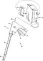
另外,在第一实施方式及其变形例中,以通过腹壁来对腹腔内(体内)的生物体组织LT进行处理的直线型能量处理器具12(参照图1A)为例进行了说明,但是,例如图18所示,也能够使用通过腹壁将处理对象组织取出到体外来进行处理的打开用直线型能量处理器具(治疗用处理器具)12a。In addition, in the first embodiment and its modifications, the linearenergy treatment instrument 12 (see FIG. For example, as shown in FIG. 18 , it is also possible to use a linear energy treatment instrument for opening (a treatment instrument for treatment) 12 a that treats the tissue to be treated by taking it out of the body through the abdominal wall.

该能量处理器具12a具备手柄22和保持部26。即,与通过腹壁来进行处理的能量处理器具12(参照图1A)不同,去除了轴24。另一方面,具有与轴24相同作用的部件被配置于手柄22内。因此,图18示出的能量处理器具12a能够与上述图1A示出的能量处理器具12同样地进行使用。Thisenergy treatment device 12 a includes ahandle 22 and a holdingportion 26 . That is, unlike the energy treatment device 12 (see FIG. 1A ), which performs treatment through the abdominal wall, theshaft 24 is eliminated. On the other hand, a member having the same function as theshaft 24 is arranged inside thehandle 22 . Therefore, theenergy treatment tool 12a shown in FIG. 18 can be used similarly to theenergy treatment tool 12 shown in FIG. 1A described above.

[第二实施方式][Second Embodiment]

接着,使用图19至图21来说明第二实施方式。本实施方式为包括各种变形例的第一实施方式的变形例。Next, a second embodiment will be described using FIGS. 19 to 21 . This embodiment is a modified example of the first embodiment including various modified examples.

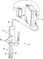
在此,例如以通过腹壁或者在腹壁外进行处理的圆型双极型能量处理器具(治疗用处理器具)312为例来说明能量处理器具。Here, the energy processing device will be described by taking, for example, a circular bipolar energy processing device (treatment device for treatment) 312 that performs treatment through the abdominal wall or outside the abdominal wall as an example.

如图19所示,治疗处理系统310具备能量处理器具312、能量源14以及脚踏开关16。外科用处理器具312具备手柄322、轴324以及可打开和关闭的保持部326。手柄322通过线缆28与能量源14相连接。As shown in FIG. 19 , thetherapeutic treatment system 310 includes anenergy treatment device 312 , anenergy source 14 and afoot switch 16 . Thesurgical treatment tool 312 includes a handle 322 , ashaft 324 , and an openable andclosable holding portion 326 . The handle 322 is connected to theenergy source 14 via thecable 28 .

在手柄322上配置有保持部打开和关闭旋钮332以及刀具驱动杆334。保持部打开和关闭旋钮332相对于手柄322可转动。当相对于手柄322例如向右转动该保持部打开和关闭旋钮332时,使保持部326的后述的脱离侧保持部(脱离侧把持部)344远离主体侧保持部(主体侧把持部)342,当向左转动时,使脱离侧保持部344接近主体侧保持部342。A holder opening and closingknob 332 and aknife driving lever 334 are disposed on the handle 322 . The holder opening and closingknob 332 is rotatable relative to the handle 322 . When the holding portion opening and closingknob 332 is turned, for example, to the right with respect to the handle 322, a later-described disengagement-side holding portion (disengagement-side grip) 344 of the holdingportion 326 is moved away from the main body-side holding portion (main-body side grip). 342 , when turning to the left, make the disengagementside holding part 344 close to the main bodyside holding part 342 .

轴324形成为圆筒状。考虑到向生物体组织LT的插入性而使该轴324适当地弯曲。当然,笔直地形成轴324也适用。Theshaft 324 is formed in a cylindrical shape. Theshaft 324 is suitably bent in consideration of insertion into the living tissueLT . Of course, forming theshaft 324 straight is also applicable.

在轴324的前端配置有保持部326。如图20A以及图20B所示,保持部326具备形成于轴324前端的主体侧保持部(第一保持部件、第一钳口)342以及相对于该主体侧保持部342可安装拆卸的脱离侧保持部(第二保持部件、第二钳口)344。在脱离侧保持部344相对于主体侧保持部342关闭的状态下,主体侧保持部342以及脱离侧保持部344的后述的保持面384、388、434、438相互接触。A holdingportion 326 is arranged at the tip of theshaft 324 . As shown in FIGS. 20A and 20B , the holdingportion 326 includes a main body side holding portion (first holding member, first jaw) 342 formed at the front end of theshaft 324 and a disengagement side that can be attached and detached from the main bodyside holding portion 342 . Holder (second holding member, second jaw) 344 . When the separation-side holding portion 344 is closed with respect to the main body-side holding portion 342 , holdingsurfaces 384 , 388 , 434 , 438 described later of the main body-side holding portion 342 and the separation-side holding portion 344 are in contact with each other.

在轴324和主体侧保持部342的外侧形成有第一管路346。该第一管路346在绕主体侧保持部342的前端边缘部的外周面一周的状态下从主体侧保持部342向轴324的基端侧延伸。Afirst conduit 346 is formed outside theshaft 324 and the main bodyside holding portion 342 . Thefirst conduit 346 extends from the main bodyside holding part 342 toward the proximal end side of theshaft 324 while going around the outer peripheral surface of the front end edge part of the main bodyside holding part 342 .

在脱离侧保持部344上形成有第二管路348。该第二管路348在绕脱离侧保持部344的头部404的边缘部一周的状态下从脱离侧保持部344的后述的通电轴324连接到主体侧保持部342和轴324内部的后述的第一通电用管356以及流体提供用管360。Asecond duct 348 is formed on the disengagement-side holding portion 344 . Thesecond pipe line 348 is connected from the later-described energizingshaft 324 of the separation-side holding portion 344 to the main body-side holding portion 342 and the back of theshaft 324 while going around the edge of thehead portion 404 of the separation-side holding portion 344 . The firstelectricity supply tube 356 and the fluid supply tube 360 are described above.

主体侧保持部342具备圆筒构件352、框架354、具有流体回收功能的第一通电用管356、第二通电用管358以及流体提供用管360。第一通电用管356通过主体侧保持部342、轴324、手柄322以及线缆28与能量源14的第一高频能量输出电路104相连接。第二通电用管358与第一通电用管356同样地通过主体侧保持部342、轴324、手柄322以及线缆28与能量源14的第二高频能量输出电路106相连接。The main bodyside holding portion 342 includes acylindrical member 352 , aframe 354 , afirst energization tube 356 having a fluid recovery function, asecond energization tube 358 , and a fluid supply tube 360 . Thefirst energization tube 356 is connected to the first high-frequencyenergy output circuit 104 of theenergy source 14 through the main bodyside holding part 342 , theshaft 324 , the handle 322 and thecable 28 . Thesecond energization tube 358 is connected to the second high frequencyenergy output circuit 106 of theenergy source 14 through the main bodyside holding part 342 , theshaft 324 , the handle 322 and thecable 28 similarly to thefirst energization tube 356 .

流体提供用管360优选例如含有硅材料等具有绝缘性的树脂材料。将该流体提供用管360用于对脱离侧保持部344的第二管路(脱离侧冷却管)348提供冷却介质。将第一通电用管356用于回收从流体提供用管360提供给第二管路348的冷却介质。The fluid supply tube 360 preferably contains an insulating resin material such as a silicon material, for example. This fluid supply pipe 360 is used to supply the cooling medium to the second pipe (departure-side cooling pipe) 348 of the detachment-side holding portion 344 . Thefirst energization pipe 356 is used to recover the cooling medium supplied from the fluid supply pipe 360 to thesecond line 348 .

这些圆筒构件352和框架354具有绝缘性。圆筒构件352与轴324的前端相连结。将框架354配置成相对于圆筒构件352固定。Thesecylindrical member 352 andframe 354 have insulation. Thecylindrical member 352 is connected to the front end of theshaft 324 . Theframe 354 is configured to be fixed relative to thecylindrical member 352 .

框架354的中心轴被开口。在该框架354的被开口的中心轴上配置第一通电用管356,该第一通电用管356被配置成能够沿着框架354的中心轴在规定范围内移动。当转动保持部打开和关闭旋钮332时,第一通电用管356例如在滚珠丝杆(未图示)的作用下能够在规定范围内移动。在第一通电用管356上形成有图20A至图20C示出的、被分成多个(例如如图20C示出的两个、或三个(未图示))且扩展的扩径部356a,来接受脱离侧保持部344的后述的通电用轴402的前端部402a。通过这种扩径部356a,使第一通电用管356的前端具有弹簧性,保持与通电用轴402的前端402a接触的状态并且柔和地保持通电用轴402的前端402a。The central axis of theframe 354 is opened. On the opened center axis of theframe 354 , afirst energization tube 356 is arranged so as to be movable within a predetermined range along the center axis of theframe 354 . When the holding portion opening and closingknob 332 is rotated, thefirst energization tube 356 can move within a predetermined range by, for example, a ball screw (not shown). Theenlarged diameter portion 356a that is divided into a plurality (for example, two or three (not shown) as shown in FIG. 20C ) and expanded as shown in FIGS. 20A to 20C is formed on thefirst energization tube 356 . , to receive thefront end portion 402a of theenergization shaft 402 described later of the detachment-side holding portion 344 . The diameter-enlargedportion 356a gives the tip of thefirst energization tube 356 a spring property, keeps thetip 402a of theenergization shaft 402 in contact with it, and gently holds thetip 402a of theenergization shaft 402 .

沿着第一通电用管356的中心轴配置有第二通电用管358。当转动保持部打开和关闭旋钮332时,第二通电用管358例如在滚珠丝杆(未图示)的作用下能够与第一通电用管356一起在规定范围内移动。在第二通电用管358的前端侧的内周面形成有向直径方向内侧突出的突起358a,使得能够与通电用轴402的连接部402b卡合和脱离。Asecond energization tube 358 is arranged along the central axis of thefirst energization tube 356 . When the holding part opening and closingknob 332 is turned, thesecond energization tube 358 can move within a predetermined range together with thefirst energization tube 356 by, for example, a ball screw (not shown). Aprotrusion 358 a protruding inward in the radial direction is formed on the inner peripheral surface of the distal end side of thesecond energization tube 358 so as to engage and detach from theconnection portion 402 b of theenergization shaft 402 .

此外,将第一通电用管356和第二通电用管358配置成相互不接触,虽然未图示,但是该第一通电用管356的外周面被具有绝缘性的材料覆盖。因此,即使第一通电用管356与第二通电用管358接触,也防止相互影响。In addition, thefirst energization tube 356 and thesecond energization tube 358 are arranged so as not to contact each other, and although not shown, the outer peripheral surface of thefirst energization tube 356 is covered with an insulating material. Therefore, even if thefirst energization tube 356 and thesecond energization tube 358 are in contact, mutual influence is prevented.

如图20A以及图20B所示,在圆筒构件352与框架354之间形成有刀具导向槽(第一流体通路)362。在该刀具导向槽362内配置有圆筒状的刀具364。该刀具364的基端部与配置于框架354基端侧的未图示的刀具用推动器的前端部的外周面相连接。该刀具用推动器的基端部与手柄322的刀具驱动杆334相连接。因此,当操作手柄322的刀具驱动杆334时,通过刀具用推动器而使刀具364移动。As shown in FIGS. 20A and 20B , a cutter guide groove (first fluid passage) 362 is formed between thecylindrical member 352 and theframe 354 . Acylindrical cutter 364 is arranged in thecutter guide groove 362 . The proximal end portion of theblade 364 is connected to the outer peripheral surface of the distal end portion of a blade pusher (not shown) disposed on the proximal end side of theframe 354 . The base end portion of the knife pusher is connected to theknife driving rod 334 of the handle 322 . Therefore, when theknife driving lever 334 of the handle 322 is operated, theknife 364 is moved by the knife pusher.

在该刀具用推动器与框架354之间形成有与刀具导向槽362连通的未图示的第一流体通气路(流体通路)。并且,在轴324或者手柄322上形成有将通过了刀具导向槽362的流体排出到外部的流体放出口(未图示)。A not-shown first fluid passage (fluid passage) communicating with thecutter guide groove 362 is formed between the cutter pusher and theframe 354 . In addition, a fluid discharge port (not shown) for discharging the fluid passing through thecutter guide groove 362 to the outside is formed on theshaft 324 or the handle 322 .

如图20A至图20C所示,在圆筒构件352的前端配置有第一连续电极(密封部件、第一接合部件)372以及多个第一离散电极(维持部件、第二接合部件)374来作为输出部件、能量放出部。第一连续电极372形成为无缝连续的圆环状。在第一连续电极372的外侧,隔开规定间隔地离散配置第一离散电极374。As shown in FIGS. 20A to 20C , a first continuous electrode (sealing member, first bonding member) 372 and a plurality of first discrete electrodes (maintaining member, second bonding member) 374 are arranged at the front end of thecylindrical member 352 to As an output part and an energy release part. The firstcontinuous electrode 372 is formed in a seamless continuous ring shape. On the outside of the firstcontinuous electrode 372 , firstdiscrete electrodes 374 are discretely arranged at predetermined intervals.

在第一连续电极372上固定有第一通电线372a的前端。第一通电线372a通过主体侧保持部342、轴324以及手柄322与线缆28相连接。第一离散电极374之间电连接,在一个第一离散电极374上固定有第二通电线374a的前端。第二通电线374a通过主体侧保持部342、轴324以及手柄322与线缆28相连接。The tip of thefirst conducting wire 372 a is fixed to the firstcontinuous electrode 372 . The firstelectric wire 372 a is connected to thecable 28 through the main bodyside holding part 342 , theshaft 324 and the handle 322 . The firstdiscrete electrodes 374 are electrically connected, and a front end of a secondelectric wire 374 a is fixed to one of the firstdiscrete electrodes 374 . The secondelectric wire 374 a is connected to thecable 28 through the main bodyside holding part 342 , theshaft 324 and the handle 322 .

第一连续电极372被配置在配置有刀具364的刀具导向槽362的边缘部与圆筒构件352的边缘部之间。将第一连续电极372配置在接近刀具导向槽362的外侧边缘部一侧。The firstcontinuous electrode 372 is arranged between the edge portion of thecutter guide groove 362 where thecutter 364 is arranged and the edge portion of thecylindrical member 352 . The firstcontinuous electrode 372 is disposed on the side close to the outer edge of thecutter guide groove 362 .

沿着大致圆环状的虚拟轨迹大致等间隔地配置相同形状的第一离散电极374。第一离散电极374例如分别形成为圆形状。第一离散电极374之间配置成相互具有大致规定间隔,并且各第一离散电极374被配置在与第一连续电极372也相距适当距离的位置处。第一离散电极374的位置位于以下位置:在进行处理时,尽可能防止相邻的第一离散电极374之间的生物体组织LT由于热量而被改性,并且尽可能防止第一离散电极374与第一连续电极372之间的生物体组织LT由于热量而被改性。The firstdiscrete electrodes 374 of the same shape are arranged at substantially equal intervals along the substantially circular virtual trajectory. The firstdiscrete electrodes 374 are respectively formed in a circular shape, for example. The firstdiscrete electrodes 374 are arranged at substantially predetermined intervals from each other, and each of the firstdiscrete electrodes 374 is also arranged at an appropriate distance from the firstcontinuous electrodes 372 . The position of the firstdiscrete electrodes 374 is located in the following position: when performing treatment, it is possible to prevent the biological tissue LT between adjacent firstdiscrete electrodes 374 from being modified due to heat, and to prevent the first discrete electrodes from being modified as much as possible. The living tissueLT between 374 and the firstcontinuous electrode 372 is modified by heat.

在第一连续电极372的外侧形成有圆环状的蒸汽放出槽382。即,在第一连续电极372与第一离散电极374之间形成有蒸汽放出槽382。该流体放出槽382与配置有刀具364的刀具导向槽362相连通。在该流体放出槽382外侧,在高于第一连续电极372表面的位置处形成有保持面(组织接触面)384。即,与第一连续电极372表面相比,主体侧保持部342的保持面384更接近脱离侧保持部344的后述的头部404。因此,保持面384起到防止蒸汽等流体放出到流体放出槽382的外侧的障壁部(dam)的作用。An annularsteam release groove 382 is formed outside the firstcontinuous electrode 372 . That is, thevapor release groove 382 is formed between the firstcontinuous electrode 372 and the firstdiscrete electrode 374 . Thefluid discharge groove 382 communicates with thecutter guide groove 362 where thecutter 364 is disposed. Outside thefluid discharge groove 382 , a holding surface (tissue contacting surface) 384 is formed at a position higher than the surface of the firstcontinuous electrode 372 . That is, the holdingsurface 384 of the main bodyside holding portion 342 is closer to ahead portion 404 described later of the separationside holding portion 344 than the surface of the firstcontinuous electrode 372 . Therefore, the holdingsurface 384 functions as a dam that prevents fluid such as steam from being released to the outside of thefluid discharge groove 382 .

在各第一离散电极374外侧形成有圆环状的蒸汽放出槽386。该流体放出槽386与配置于第一连续电极372外侧的流体放出槽382以及刀具导向槽362相连通。在该流体放出槽386外侧,在高于第一离散电极374表面的位置处形成有保持面(组织接触面)388。因此,保持面388起到防止蒸汽等流体放出到流体放出槽386的外侧的障壁部(dam)的作用。An annularsteam release groove 386 is formed outside each firstdiscrete electrode 374 . Thefluid discharge groove 386 communicates with thefluid discharge groove 382 disposed outside the firstcontinuous electrode 372 and thecutter guide groove 362 . Outside thefluid discharge groove 386 , a holding surface (tissue contacting surface) 388 is formed at a position higher than the surface of the firstdiscrete electrode 374 . Therefore, the holdingsurface 388 functions as a dam that prevents fluid such as steam from being released to the outside of thefluid discharge groove 386 .

如图20A至图21所示,上述第一管路346具备固定在主体侧保持部342的圆筒构件352的最外周的主体侧冷却管392。该冷却管392被配置于主体侧保持部342和轴324的外周面,延伸到轴324的基端侧。该冷却管392例如是铜等具有良好的导热性。在该冷却管392中例如以循环的方式使冷却水(液体)、冷却气(气体)等冷却介质流动并被排出。此外,图21示出的以附图标记392a表示的一侧为流体提供用冷却管392,以附图标记392b表示一侧为流体回收用冷却管392。As shown in FIGS. 20A to 21 , thefirst conduit 346 includes a body-side cooling pipe 392 fixed to the outermost periphery of thecylindrical member 352 of the body-side holding portion 342 . Thecooling pipe 392 is disposed on the outer peripheral surfaces of the main bodyside holding portion 342 and theshaft 324 , and extends to the base end side of theshaft 324 . Thecooling pipe 392 is, for example, copper, which has good thermal conductivity. A cooling medium such as cooling water (liquid) or cooling air (gas) flows through thecooling pipe 392 and is discharged, for example, in a circulating manner. In addition, the side indicated byreference numeral 392a shown in FIG. 21 is thecooling pipe 392 for fluid supply, and the side indicated byreference numeral 392b is thecooling pipe 392 for fluid recovery.

在主体侧保持部342的保持面388上配置有例如铜板等导热性良好的主体侧冷却板394。该冷却板394在与冷却管392紧密接合的状态下固定在圆筒构件352的前端。因此,当使冷却介质通过冷却管392内时,来自该冷却介质的热量从冷却管392导热到冷却板394。即,对冷却板394进行冷却。On the holdingsurface 388 of the body-side holding portion 342, a body-side cooling plate 394 having good thermal conductivity such as a copper plate is arranged. Thecooling plate 394 is fixed to the front end of thecylindrical member 352 in a state of being in close contact with thecooling pipe 392 . Therefore, when the cooling medium passes through thecooling pipe 392 , the heat from the cooling medium is transferred from thecooling pipe 392 to thecooling plate 394 . That is, thecooling plate 394 is cooled.

并且,在本变形例中,在能量源14中,冷却输出电路108a代替在第一实施方式中说明的温度测量电路108与控制部102相连接。该冷却输出电路108a能够根据来自控制部102的指示使冷却介质流过外科用处理器具312的冷却管392。Furthermore, in this modified example, in theenergy source 14, thecooling output circuit 108a is connected to thecontrol unit 102 instead of thetemperature measurement circuit 108 described in the first embodiment. Thecooling output circuit 108 a can cause the cooling medium to flow through the coolingtube 392 of thesurgical treatment tool 312 according to an instruction from thecontrol unit 102 .

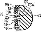
另一方面,脱离侧保持部344具备通电用轴402以及具有绝缘性的头部404。通电用轴402的截面呈圆形状,一端形成为逐渐变细,另一端被固定于头部404。通电用轴402大致具有三个筒状部件412、414、416紧密接合的三层结构。通电用轴402的内侧(内层)412为具有导电性的筒状部件,中间层414为具有绝缘性的筒状部件,外侧(外层)416为具有导电性的筒状部件。On the other hand, the disengagement-side holding portion 344 includes anenergization shaft 402 and an insulatinghead portion 404 . Theenergization shaft 402 has a circular cross section, one end is tapered, and the other end is fixed to thehead 404 . Theconduction shaft 402 generally has a three-layer structure in which threecylindrical members 412 , 414 , and 416 are tightly bonded. The inner side (inner layer) 412 of theconduction shaft 402 is a conductive cylindrical member, theintermediate layer 414 is an insulating cylindrical member, and the outer side (outer layer) 416 is a conductive cylindrical member.

并且,内层412利用其前端部(通电用轴402的前端402a)与第一通电用管356的扩径部356a电连接。在外层416的前端部侧的外周面形成有连接部(凹槽部)402b,该连接部(凹槽部)402b用于与第二通电用管358的突起358a卡合。此外,优选通过涂敷处理等以具有绝缘性的材料覆盖外层416的外周面中的连接部402b以外的部分。Furthermore, theinner layer 412 is electrically connected to the diameter-enlargedportion 356a of thefirst energization tube 356 at its tip (thetip 402a of the energization shaft 402 ). A connection portion (groove portion) 402 b for engaging with theprotrusion 358 a of thesecond energization tube 358 is formed on the outer peripheral surface on the front end side of theouter layer 416 . In addition, it is preferable to cover the portion of the outer peripheral surface of theouter layer 416 other than theconnection portion 402b with an insulating material by coating treatment or the like.

在头部404上以与主体侧保持部342的第一连续电极372以及第一离散电极374相向的方式配置有第二连续电极(密封部件、第一接合部件)422和第二离散电极(维持部件、第二接合部件)424。在第二连续电极422上固定有第三通电线422a的一端。该第三通电线422a的另一端通过通电用轴402的外层416和中间层414与内层412电连接。在第二离散电极424上固定有第四通电线424a的一端。该第四通电线424a的另一端与通电用轴402的外层416电连接。The second continuous electrode (sealing member, first bonding member) 422 and the second discrete electrode (sustaining component, second engaging component) 424. One end of thethird conducting wire 422 a is fixed to the secondcontinuous electrode 422 . The other end of thethird conducting wire 422 a is electrically connected to theinner layer 412 through theouter layer 416 and theintermediate layer 414 of theshaft 402 for conducting electricity. One end of the fourthelectric wire 424 a is fixed to the seconddiscrete electrode 424 . The other end of thefourth energization wire 424 a is electrically connected to theouter layer 416 of theenergization shaft 402 .

在配置于头部404的第二连续电极372内侧形成有圆环状的刀具接受部426来接受刀具364的刃部。另一方面,在第二连续电极422外侧形成有圆环状的流体放出槽432。在该流体放出槽432外侧,在高于第二连续电极422的表面的位置处形成有保持面(组织接触面)434。即,与第二连续电极422的表面相比,脱离侧保持部344的保持面434更接近主体侧保持部342。因此,保持面434起到防止蒸汽等流体放出到蒸汽放出槽432的外侧的障壁部(dam)的作用。An annularcutter receiving portion 426 is formed inside the secondcontinuous electrode 372 disposed on thehead portion 404 to receive the blade portion of thecutter 364 . On the other hand, an annularfluid discharge groove 432 is formed outside the secondcontinuous electrode 422 . Outside thefluid discharge groove 432 , a holding surface (tissue contacting surface) 434 is formed at a position higher than the surface of the secondcontinuous electrode 422 . That is, the holdingsurface 434 of the separation-side holding portion 344 is closer to the body-side holding portion 342 than the surface of the secondcontinuous electrode 422 . Therefore, the holdingsurface 434 functions as a dam that prevents fluid such as steam from being released to the outside of thesteam release groove 432 .

在各第二离散电极424外侧形成有圆环状的蒸汽放出槽436。该流体放出槽436与配置于第二连续电极422外侧的流体放出槽432相连通。在该流体放出槽436外侧,在高于第二离散电极424表面的位置处形成有保持面(组织接触面)438。因此,保持面438起到防止蒸汽等流体放出到流体放出槽436的外侧的障壁部(dam)的作用。An annularsteam release groove 436 is formed outside each seconddiscrete electrode 424 . Thefluid discharge groove 436 communicates with thefluid discharge groove 432 disposed outside the secondcontinuous electrode 422 . Outside thefluid discharge groove 436 , a holding surface (tissue contacting surface) 438 is formed at a position higher than the surface of the seconddiscrete electrode 424 . Therefore, the holdingsurface 438 functions as a dam that prevents fluid such as steam from being released to the outside of thefluid discharge groove 436 .

并且,流体放出槽432与头部404以及通电用轴402的内层412内侧的流体放出路432a连通。流体放出路432a位于偏离通电用轴402的中心轴的位置处,通过主体侧保持部342的第一通电用轴356的两个扩径部356a(参照图20C)之间,与第一通电用管356的外周面和第二通电用管358的内周面之间连通。在轴324或者手柄322上形成有流体放出口(未图示),该流体放出口将通过了第一通电用管356的外周面和第二通电用管358的内周面之间的流体排出到外部。Furthermore, thefluid discharge groove 432 communicates with thehead 404 and thefluid discharge passage 432 a inside theinner layer 412 of theenergization shaft 402 . Thefluid discharge path 432a is located at a position deviated from the central axis of theshaft 402 for current conduction, passes between the twoenlarged diameter portions 356a (refer to FIG. The outer peripheral surface of thetube 356 communicates with the inner peripheral surface of thesecond energization tube 358 . A fluid discharge port (not shown) is formed on theshaft 324 or the handle 322, and the fluid discharge port discharges the fluid that has passed between the outer peripheral surface of thefirst energization tube 356 and the inner peripheral surface of thesecond energization tube 358. to the outside.

如图20A至图21所示,第二管路348从通电用轴402的下端到达头部404的顶部,在从该顶部起绕头部404的外缘部一周的状态下,再次通过通电用轴402内部而插通到通电用轴402的下端。第二管路348的两个端部位于通电用轴402的前端部402a。此外,图21中的第二管路348中的以附图标记348a表示的一侧用于提供流体,以附图标记348b表示的一侧用于回收流体。第二管路348从通电用轴402的前端部402a到达头部404的顶部,在从该顶部起绕头部404的外缘部一周的状态下,再次通过通电用轴402内部而插通到通电用轴402的前端部402a。As shown in FIGS. 20A to 21 , thesecond pipeline 348 reaches the top of thehead 404 from the lower end of theenergization shaft 402 , and passes through the energization again while going around the outer edge of thehead 404 from the top. The lower end of theshaft 402 for conduction is inserted inside theshaft 402 . Both end portions of thesecond pipe line 348 are located at thefront end portion 402 a of thecurrent supply shaft 402 . In addition, the side of thesecond pipeline 348 in FIG. 21 indicated byreference numeral 348a is used for supplying fluid, and the side indicated byreference numeral 348b is used for recovering fluid. Thesecond pipeline 348 reaches the top of thehead 404 from thefront end 402a of theenergization shaft 402, and passes through the inside of theenergization shaft 402 again in a state where it goes around the outer edge of thehead 404 from the top. Thefront end portion 402a of theshaft 402 for conduction.

并且,第二管路348的流体提供用的端部与流体提供用管360相连接,第二管路348的流体回收用的端部与第一通电管(流体回收用管)356相连接。因此,当在第二管路348与流体提供用管360和第一通电管(流体回收用管)356连接的状态下使冷却水等流过流体提供用管360时,通过第二管路348从第一通电管(流体回收用管)356回收冷却水等。即,能够使冷却水等流体在第二管路348中循环。In addition, the fluid supply end of thesecond line 348 is connected to the fluid supply tube 360 , and the fluid recovery end of thesecond line 348 is connected to the first electric tube (fluid recovery tube) 356 . Therefore, when cooling water or the like flows through the fluid supply tube 360 in a state where thesecond tube 348 is connected to the fluid supply tube 360 and the first energization tube (fluid recovery tube) 356 , thesecond tube 348 Cooling water and the like are recovered from the first energization pipe (pipe for fluid recovery) 356 . That is, fluid such as cooling water can be circulated in thesecond pipe line 348 .

在脱离侧保持部344的保持面434、438上配置有例如铜板等导热性良好的脱离侧冷却板444。该冷却板444在与第二管路(冷却管)348紧密接合的状态下固定到头部404。因此,当使冷却介质通过第二管路348内时,来自该冷却介质的热量从第二管路348导热到冷却板444。即,对冷却板444进行冷却。On the holdingsurfaces 434 and 438 of the separation-side holding portion 344 , a separation-side cooling plate 444 having good thermal conductivity such as a copper plate is disposed. Thiscooling plate 444 is fixed to thehead portion 404 in a state of being closely engaged with the second piping (cooling pipe) 348 . Therefore, when the cooling medium passes through thesecond pipe 348 , the heat from the cooling medium is transferred from thesecond pipe 348 to thecooling plate 444 . That is, thecooling plate 444 is cooled.

接着,根据图11示出的流程图来说明本实施方式所涉及的治疗处理系统310的作用。Next, the operation of themedical treatment system 310 according to this embodiment will be described based on the flowchart shown in FIG. 11 .

手术师预先操作图10示出的能量源14的显示部110来设定治疗处理系统310的输出条件(步骤101)。具体地说,预先设定来自第一高频能量输出电路104和第二高频能量输出电路106的输出(设定功率P1set[W]、P2set[W])、生物体组织LT的阻抗Z的阈值Z1、Z2以及来自第二高频能量输出电路106的一次输出时间(设定时间t1、t2)等。The operator operates thedisplay unit 110 of theenergy source 14 shown in FIG. 10 in advance to set the output conditions of the therapeutic treatment system 310 (step 101 ). Specifically, the outputs from the first high-frequencyenergy output circuit 104 and the second high-frequency energy output circuit 106 (set powers P1set[W], P2set[W]), the impedance Z of the living tissueLT are set in advance. The thresholds Z1, Z2 of the second high-frequencyenergy output circuit 106 output time (setting time t1, t2) and so on.

在主体侧保持部342相对于脱离侧保持部344关闭的状态下,例如将外科用处理器具312的保持部326和轴324通过腹壁插入到腹腔内。使外科用处理器具312的主体侧保持部342和脱离侧保持部344与要进行处理的生物体组织LT相对峙。In a state where the main bodyside holding portion 342 is closed relative to the disengagementside holding portion 344 , for example, the holdingportion 326 and theshaft 324 of thesurgical treatment instrument 312 are inserted into the abdominal cavity through the abdominal wall. The body-side holding portion 342 and the separation-side holding portion 344 of thesurgical treatment tool 312 are made to face the living tissueLT to be treated.

为了利用主体侧保持部342和脱离侧保持部344来把持要进行处理的生物体组织LT,操作手柄322的把持部打开和关闭旋钮332。此时,相对于手柄322例如向右转动把持部打开和关闭旋钮332。使通电用管356相对于轴324的框架354向前端部侧移动。因此,主体侧保持部342与脱离侧保持部344之间打开,能够使脱离侧保持部344从主体侧保持部342脱离。In order to grasp the living tissueLT to be treated by the main bodyside holding part 342 and the detachmentside holding part 344, the grip part of the handle 322 is operated to open and close theknob 332. At this time, the grip opening and closingknob 332 is turned, for example, rightward with respect to the handle 322 . Theconduction tube 356 is moved toward the front end side with respect to theframe 354 of theshaft 324 . Therefore, the space between the main bodyside holding part 342 and the detachmentside holding part 344 is opened, and the detachmentside holding part 344 can be detached from the main bodyside holding part 342 .

并且,将要进行处理的生物体组织LT配置在主体侧保持部342的第一连续电极372以及第一离散电极374与脱离侧保持部344的第二连续电极422以及第二离散电极424之间。在这种状态下,例如向左转动手柄322的把持部打开和关闭旋钮332。因此,脱离侧保持部344相对于主体侧保持部342关闭。这样,在主体侧保持部342与脱离侧保持部344之间保持处理对象的生物体组织LTAnd, the living tissueLT to be treated is arranged between the firstcontinuous electrode 372 and the firstdiscrete electrode 374 of the main bodyside holding part 342 and the secondcontinuous electrode 422 and the seconddiscrete electrode 424 of the separationside holding part 344 . In this state, turning the grip portion of the handle 322 to the left, for example, opens and closes theknob 332 . Therefore, the disengagement-side holding portion 344 is closed relative to the main body-side holding portion 342 . In this way, the living tissue LT to be treated is held between the main bodyside holding part 342 and the detachmentside holding part 344 .

在这种状态下,操作脚踏开关16的踏板16a。能量源14的控制部102判断开关16的踏板16a是否通过手术师的操作被按压而切换为接通(步骤102)。In this state, thepedal 16a of thefoot switch 16 is operated. Thecontrol unit 102 of theenergy source 14 judges whether or not the pedal 16a of theswitch 16 is pressed and switched on by the operator's operation (step 102).

在判断为开关16的踏板16a被按压而切换为接通时,从能量源14的第一高频能量输出电路104对第一连续电极372和第二连续电极422之间的生物体组织(第一区域的生物体组织)LT提供高频能量(步骤103)。When it is judged that the pedal 16a of theswitch 16 is pressed and switched on, the first high-frequencyenergy output circuit 104 of theenergy source 14 is applied to the living tissue between the firstcontinuous electrode 372 and the second continuous electrode 422 (the second continuous electrode 422 ). A region of biological tissue) LT provides high-frequency energy (step 103).

因此,第一高频能量输出电路104对主体侧保持部342的第一连续电极372和脱离侧保持部344的第二连续电极422之间的处理对象的生物体组织LT通高频电流,使被把持在电极372、422之间的生物体组织LT内产生焦耳热来对生物体组织LT本身加热。因而,生物体组织LT通过第一连续电极372和第二连续电极422而被圆环状地连续改性。Therefore, the first high-frequencyenergy output circuit 104 passes a high-frequency current to the biological tissueLT of the treatment target between the firstcontinuous electrode 372 of the main bodyside holding part 342 and the secondcontinuous electrode 422 of the separationside holding part 344, Joule heat is generated in the living tissueLT held between theelectrodes 372 and 422 to heat the living tissueLT itself. Thus, the living tissueLT is continuously modified in an annular shape by the firstcontinuous electrode 372 and the secondcontinuous electrode 422 .

此时,通过第一连续电极372、第二连续电极422以及高频能量输出电路104测量所把持的生物体组织LT的阻抗Z。如图6B所示,开始进行处理时的阻抗Z0例如为60[Ω]左右。并且,随着高频电流流入到生物体组织LT而生物体组织LT被烧灼,阻抗Z的值上升。At this time, the impedance Z of the grasped living tissueLT is measured by the firstcontinuous electrode 372 , the secondcontinuous electrode 422 and the high-frequencyenergy output circuit 104 . As shown in FIG. 6B , the impedance Z0 at the start of processing is, for example, about 60 [Ω]. And, as the high-frequency current flows into the living tissueLT to burn the living tissueLT , the value of the impedance Z increases.

这样,随着生物体组织LT被烧灼,从生物体组织LT放出流体(液体(血液)和/或气体(水蒸气))。此时,与第一连续电极372和第二连续电极422相比,主体侧保持部342的保持面384和脱离侧保持部344的保持面434与生物体组织LT接合更紧密。因此,保持面384、434作为抑制流体向主体侧保持部342和脱离侧保持部344外侧流出的障壁部(dam)而发挥功能。In this way, as the living tissueLT is cauterized, fluid (liquid (blood) and/or gas (steam)) is released from the living tissueLT . At this time, compared with the firstcontinuous electrode 372 and the secondcontinuous electrode 422, the holdingsurface 384 of the main bodyside holding part 342 and the holdingsurface 434 of the separationside holding part 344 are more closely bonded to the living tissueLT . Therefore, the holdingsurfaces 384 and 434 function as dams that suppress fluid from flowing out of the main bodyside holding portion 342 and the separationside holding portion 344 .

因而,使从生物体组织LT放出的流体从第一连续电极372外侧的蒸汽放出槽382流入到第一连续电极372内侧的刀具导向槽362,或者直接流入到刀具导向槽362,例如通过吸引来从主体侧保持部342流入到轴324。在从生物体组织LT放出流体的期间,使该流体持续流入到刀具导向槽362。因此,防止在温度上升的状态下从生物体组织LT放出的流体产生热传播,能够防止对不是处理对象的部分带来影响。Therefore, the fluid released from the biological tissueLT flows into thecutter guide groove 362 inside the firstcontinuous electrode 372 from thesteam release groove 382 outside the firstcontinuous electrode 372, or directly flows into thecutter guide groove 362, for example, by suction to flow into theshaft 324 from the main bodyside holding portion 342 . While the fluid is discharged from the living tissueLT , the fluid continues to flow into thecutter guide groove 362 . Therefore, it is possible to prevent heat propagation of the fluid discharged from the living tissueLT in a state where the temperature is raised, and to prevent influence on parts not to be treated.

另外,使从生物体组织LT放出的流体流入到第二连续电极422外侧的流体放出槽432,例如通过吸引使其通过形成于头部404和通电轴402内的流体放出路432a,从第一通电用管356内部流入到轴324。在从生物体组织LT放出流体的期间,使该流体持续流入到流体放出路432a。因此,防止在温度上升的状态下从生物体组织LT放出的流体产生热传播,能够防止对不是处理对象的部分带来影响。In addition, the fluid discharged from the living tissueLT flows into thefluid discharge groove 432 on the outside of the secondcontinuous electrode 422, for example, is sucked to pass through thefluid discharge channel 432a formed in thehead 404 and theenergization shaft 402, and flows from the secondcontinuous electrode 422 to thefluid discharge channel 432a. Atube 356 for electricity flows into theshaft 324 inside. While the fluid is discharged from the living tissueLT , the fluid continues to flow into thefluid discharge path 432a. Therefore, it is possible to prevent heat propagation of the fluid discharged from the living tissueLT in a state where the temperature is raised, and to prevent influence on parts not to be treated.

接着,控制部102判断根据来自高频能量输出电路104的信号而计算出的高频能量输出时的阻抗Z是否大于等于利用显示部110预先设定(步骤101)的阈值Z1(如图6B所示,在此大约为1000[Ω])(步骤104)。阈值Z1例如位于已知的阻抗Z的值的上升率变慢的位置处。并且,在判断为阻抗Z小于阈值Z1的情况下,处理返回到步骤103。即,继续提供用于对被把持在主体侧保持部342的第一连续电极372和脱离侧保持部344的第二连续电极422之间的生物体组织LT进行处理的高频能量。Next, thecontrol unit 102 judges whether the impedance Z during the high-frequency energy output calculated from the signal from the high-frequencyenergy output circuit 104 is greater than or equal to the threshold value Z1 (as shown in FIG. 6B ) preset (step 101) by thedisplay unit 110. , here approximately 1000 [Ω]) (step 104). The threshold Z1 is located, for example, at a position where the rate of rise of the value of the known impedance Z becomes slow. And, when it is determined that the impedance Z is smaller than the threshold value Z1 , the process returns to step 103 . That is, the high-frequency energy for treating the living tissueLT held between the firstcontinuous electrode 372 of the main bodyside holding part 342 and the secondcontinuous electrode 422 of the separationside holding part 344 continues to be supplied.

在判断为阻抗Z大于阈值Z1的情况下,从控制部102对第一高频能量输出电路104传输信号。并且,停止从第一高频能量输出电路104向第一连续电极372和第二连续电极422的输出(步骤105)。When it is determined that the impedance Z is larger than the threshold value Z1 , a signal is transmitted from thecontrol unit 102 to the first high-frequencyenergy output circuit 104 . And the output from the 1st high-frequencyenergy output circuit 104 to the 1stcontinuous electrode 372 and the 2ndcontinuous electrode 422 is stopped (step 105).

接着,从能量源14的第二高频能量输出电路106对第一离散电极374和第二离散电极424之间的生物体组织(第二区域的生物体组织)LT提供能量(步骤106)。即,与从第一高频能量输出电路104对第一连续电极372和第二连续电极422之间的生物体组织LT提供能量的时间错开地(输出定时错开的状态),如图12A的中段所示那样从第二高频能量输出电路106对第一离散电极374和第二离散电极424之间的生物体组织LT通高频电流。Then, from the second high-frequencyenergy output circuit 106 of theenergy source 14, energy is provided to the biological tissue (the biological tissue in the second region)LT between the firstdiscrete electrode 374 and the second discrete electrode 424 (step 106) . That is, with the first high-frequencyenergy output circuit 104 providing energy to the living tissueLT between the firstcontinuous electrode 372 and the secondcontinuous electrode 422, the time is staggered (the output timing is staggered), as shown in FIG. 12A As shown in the middle section, a high-frequency current is passed from the second high-frequencyenergy output circuit 106 to the living tissueLT between the firstdiscrete electrode 374 and the seconddiscrete electrode 424 .

因此,高频电流流过被把持在主体侧保持部342和脱离侧保持部344之间的生物体组织LT,通过焦耳热的作用使生物体组织LT发热并开始组织的烧灼(组织的改性)。于是,通过第一离散电极374和第二离散电极424,这些离散电极374、424之间的生物体组织LT被离散地改性。此时,由第二高频能量输出电路106通过第一离散电极374和第二离散电极424来测量所把持的生物体组织LT的阻抗Z。并且,随着高频电流流过生物体组织LT而生物体组织LT被烧灼,阻抗Z的值上升。Therefore, a high-frequency current flows through the living tissueLT grasped between the main bodyside holding part 342 and the detachmentside holding part 344, and the living tissueLT is heated by the action of Joule heat to start cauterization of the tissue (tissue ablation). modified). Then, by the firstdiscrete electrode 374 and the seconddiscrete electrode 424, the living tissueLT between thesediscrete electrodes 374, 424 is discretely modified. At this time, the impedance Z of the held biological tissueLT is measured by the second high-frequencyenergy output circuit 106 through the firstdiscrete electrode 374 and the seconddiscrete electrode 424 . And, as the high-frequency current flows through the living tissueLT to burn the living tissueLT , the value of the impedance Z increases.

并且,判断开始从第二高频能量输出电路106进行输出之后是否经过了设定时间t1(步骤107)。在经过了设定时间t1时,停止从第二高频能量输出电路106向第一离散电极374和第二离散电极424的输出(步骤108)。Then, it is determined whether or not a set time t1 has elapsed since the output from the second high-frequencyenergy output circuit 106 was started (step 107). When the set time t1 has elapsed, the output from the second high-frequencyenergy output circuit 106 to the firstdiscrete electrodes 374 and the seconddiscrete electrodes 424 is stopped (step 108 ).

紧接着,如图12A的下段所示,冷却输出电路108a使冷却介质流过第一管路346和第二管路348(步骤109)。因此,通过导热率较高的与第一管路346和第二管路348的外周面紧密接合的冷却板394、444而生物体组织LT被冷却。因而,在与冷却板394、444紧密接合的部分处抑制从第一离散电极374和第二离散电极424之间的处理对象的生物体组织LT扩散出的热量的影响。即,通过冷却处理对象的生物体组织LT周围的生物体组织LT来抑制来自处理对象的生物体组织LT的热传播。Next, as shown in the lower section of FIG. 12A , thecooling output circuit 108 a makes the cooling medium flow through thefirst pipeline 346 and the second pipeline 348 (step 109 ). Therefore, the living tissueLT is cooled by the coolingplates 394 , 444 that are in close contact with the outer peripheral surfaces of thefirst conduit 346 and thesecond conduit 348 having high thermal conductivity. Therefore, the influence of the heat diffused from the living tissueLT of the treatment target between the firstdiscrete electrode 374 and the seconddiscrete electrode 424 is suppressed at the portion in close contact with the coolingplates 394 and 444 . That is, heat transferfrom the living tissueLT to be treated is suppressed by cooling the living tissue LT around the living tissueLT to be treated.

并且,判断开始使冷却介质流过第一管路346和第二管路348起是否经过了设定时间t2(步骤110)。在经过了设定时间t2时,停止从冷却输出电路108a提供冷却介质(步骤111)。Then, it is judged whether or not a set time t2 has elapsed since the cooling medium was started to flow through thefirst line 346 and the second line 348 (step 110 ). When the set time t2 has elapsed, supply of the cooling medium from thecooling output circuit 108a is stopped (step 111).

紧接着,从第二高频能量输出电路106对第一离散电极374和第二离散电极424提供能量(步骤112)。然后,判断第一离散电极374和第二离散电极424之间的阻抗Z是否达到阈值Z2(步骤113)。在没有达到的情况下,返回到步骤106,再次以设定时间t1从第二高频能量输出电路106进行输出。即,直到阻抗Z达到阈值Z2为止反复进行生物体组织LT的烧灼和冷却。Next, energy is supplied from the second high-frequencyenergy output circuit 106 to the firstdiscrete electrode 374 and the second discrete electrode 424 (step 112 ). Then, it is judged whether the impedance Z between the firstdiscrete electrode 374 and the seconddiscrete electrode 424 reaches the threshold Z2 (step 113 ). If it has not been reached, it returns to step 106 and outputs from the second high-frequencyenergy output circuit 106 again for the set time t1. That is, cauterization and cooling of the living tissueLT are repeated until the impedance Z reaches the threshold value Z2.

并且,在阻抗Z达到阈值Z2时,使冷却介质从冷却输出电路108a流入到第一管路346和第二管路348,通过冷却板394、444来对生物体组织LT进行冷却(步骤114)。判断是否使冷却介质仅流动了设定时间t2(步骤115)。在使冷却介质仅流动了设定时间t2之后,停止提供冷却介质来停止对生物体组织LT进行冷却(步骤116)。And, when the impedance Z reaches the threshold Z2, the cooling medium flows from thecooling output circuit 108a into thefirst pipeline 346 and thesecond pipeline 348, and the living tissueLT is cooled by the coolingplates 394, 444 (step 114 ). It is judged whether or not the cooling medium has been allowed to flow for only the set time t2 (step 115). After the cooling medium is allowed to flow for the set time t2, the supply of the cooling medium is stopped to stop cooling the living tissueLT (step 116).

在结束这一系列处理之后,从扬声器112发出蜂鸣声来通知手术师处理已结束(步骤117)。After the series of processing ends, a buzzer is emitted from thespeaker 112 to notify the operator that the processing has ended (step 117).

在此,对使用具有这种作用的治疗处理系统310来如图22A至图22C所示那样,使例如在轴方向上并行设置的小肠的肠道IC1、IC2之间接合成密封状态的情况进行说明。Here, as shown in FIG. 22A to FIG. 22C by using thetherapeutic treatment system 310 having such a function, for example, the intestinal tracts IC1 and IC2 of the small intestine arranged in parallel in the axial direction are joined into a sealed state. Be explained.

操作能量源14的显示部110来进行各种设定。Various settings are performed by operating thedisplay unit 110 of theenergy source 14 .

利用主体侧保持部342的保持面384、388以及脱离侧保持部344的保持面434、438,以夹持两个肠道IC1、IC2的端部之间的壁面的方式保持沿轴方向紧挨着的一对肠道IC1、IC2Utilize the holding surfaces 384, 388 of the main bodyside holding portion 342 and the holding surfaces 434, 438 of the disengagementside holding portion 344 to hold the wall surface between the ends of the two intestinal tracts IC1 , IC2 in the axial direction. A pair of intestines IC1 , IC2 next to each other.

在这种状态下,当按压脚踏开关16的踏板16a时,对第一连续电极372和第二连续电极422之间的生物体组织LT提供高频能量。因此,通过第一连续电极372和第二连续电极422来对肠道IC1、IC2之间进行加热使其改性。In this state, when the pedal 16 a of thefoot switch 16 is pressed, high-frequency energy is supplied to the living tissueLT between the firstcontinuous electrode 372 and the secondcontinuous electrode 422 . Therefore, the firstcontinuous electrode 372 and the secondcontinuous electrode 422 are used to heat between the intestinal tracts IC1 and IC2 to modify them.

并且,在第一连续电极372和第二连续电极422之间的生物体组织LT达到规定的阈值Z1时停止来自第一高频能量输出电路104的输出。And, when the living tissueLT between the firstcontinuous electrode 372 and the secondcontinuous electrode 422 reaches a predetermined threshold Z1, the output from the first high-frequencyenergy output circuit 104 is stopped.

在第一连续电极372和第二连续电极422之间的生物体组织LT的阻抗Z达到规定的阈值Z1时,通过第一连续电极372和第二连续电极422而肠道IC1、IC2之间已被加热且改性接合。即,第一连续电极372和第二连续电极422将肠道IC1、IC2的端部之间密封为圆环状。When the impedance Z of the biological tissue LT between the firstcontinuous electrode 372 and the secondcontinuous electrode 422 reaches the specified threshold Z1, the intestinal tract IC1 and IC2 pass through the firstcontinuous electrode 372 and the secondcontinuous electrode 422 Between has been heated and modified joint. That is, the firstcontinuous electrode 372 and the secondcontinuous electrode 422 seal the ends of the intestinal tracts IC1 , IC2 in a ring shape.

紧接着,从第二高频能量输出电路106对第一离散电极374和第二离散电极424之间的生物体组织LT提供能量。因此,通过第一离散电极374和第二离散电极424来对肠道IC1、IC2之间进行加热并使其改性。Next, energy is supplied from the second high-frequencyenergy output circuit 106 to the living tissueLT between the firstdiscrete electrode 374 and the seconddiscrete electrode 424 . Therefore, the firstdiscrete electrode 374 and the seconddiscrete electrode 424 are used to heat and modify the space between the intestinal tracts IC1 , IC2 .

并且,经过设定时间t1之后,暂时停止第二高频能量输出电路106,以规定的设定时间t2从冷却输出电路108a对第一管路346和第二管路348提供冷却介质。Then, after the set time t1 has elapsed, the second high-frequencyenergy output circuit 106 is temporarily stopped, and the cooling medium is supplied from thecooling output circuit 108a to thefirst line 346 and thesecond line 348 for a predetermined set time t2.

紧接着,从第二高频能量输出电路106进行输出,一边进行烧灼一边测量阻抗Z。Next, the output is output from the second high-frequencyenergy output circuit 106, and the impedance Z is measured while performing cautery.

并且,判断第一离散电极374与第二离散电极424之间的生物体组织LT是否达到规定的阈值Z2。在没有达到时,再次从第二高频能量输出电路106进行输出以及停止输出、提供冷却介质以及停止提供冷却介质后测量阻抗Z。另一方面,在到达时,停止来自第二高频能量输出电路106的输出、提供冷却介质以及停止提供冷却介质,之后发出蜂鸣声并结束处理。Then, it is determined whether the living tissueLT between the firstdiscrete electrode 374 and the seconddiscrete electrode 424 has reached a predetermined threshold value Z2. When not reached, the impedance Z is measured after outputting and stopping the output from the second high-frequencyenergy output circuit 106 again, supplying the cooling medium, and stopping supplying the cooling medium. On the other hand, when it arrives, the output from the second high-frequencyenergy output circuit 106 is stopped, the supply of the cooling medium is stopped, and the supply of the cooling medium is stopped, after which a buzzer sounds and the process ends.

在第一离散电极374和第二离散电极424之间的生物体组织LT的阻抗Z达到规定的阈值Z2时,通过第一离散电极374和第二离散电极424而肠道IC1、IC2之间被加热且已改性接合。即,第一离散电极374和第二离散电极424进行离散接合,使得肠道IC1、IC2的端部之间中的被密封为圆环状的部分的外侧的生物体组织之间紧密接合。When the impedance Z of the biological tissueLT between the firstdiscrete electrode 374 and the seconddiscrete electrode 424 reaches the prescribed threshold Z2, the intestinal tract IC1 and IC2 pass through the firstdiscrete electrode 374 and the seconddiscrete electrode 424 between heated and modified joints. That is, the firstdiscrete electrode 374 and the seconddiscrete electrode 424 are discretely bonded so that the living tissues outside the ring-sealed portion between the ends of the intestinal tractsIC1 and IC2 are closely bonded. .

并且,保持在主体侧保持部342和脱离侧保持部344之间把持肠道IC1、IC2的状态,操作图19示出的刀具驱动把手334,使刀具364从图20B示出的状态起沿着刀具导向槽362前进。随着刀具364前进,利用其前端的刃部,将通过第一连续电极372和第二连续电极422而被改性接合的部位的内侧切成圆形状。因此,如图22C所示,肠道IC1、IC2的壁面的密封为大致圆形状之间的部分被切断,从而确保肠道IC1、IC2之间的圆形状的连通状态。And, keeping the state of holding the intestines IC1 and IC2 between the main bodyside holding part 342 and the disengagementside holding part 344, operate theknife driving handle 334 shown in FIG. 19 to make theknife 364 start from the state shown in FIG. 20B Advance along thecutter guide groove 362 . As thecutter 364 advances, the inside of the portion reformed and bonded by the firstcontinuous electrode 372 and the secondcontinuous electrode 422 is cut into a circular shape by the blade portion at the tip. Therefore, as shown in FIG. 22C , the portion between the walls of the intestinal tracts IC1 and IC2 that are sealed in a substantially circular shape is cut off, thereby ensuring a circular communication state between the intestinal tracts IC1 and IC2 .

在这种状态下操作刀具驱动把手334来使刀具364后退。之后,操作手柄322的保持部打开和关闭旋钮332来打开主体侧保持部342和脱离侧保持部344。此时,例如图22C所示,通过第一连续电极372和第二连续电极422而连续接合的外侧的部分被离散地改性。并且如上所述,将从第二高频能量输出电路106对第一离散电极374和第二离散电极424提供的输出设定得较高,因此被离散地改性并接合的部分牢固地接合,因此具有耐剥离性。In this state, theknife drive handle 334 is operated to retract theknife 364 . After that, the holding portion opening and closingknob 332 of the handle 322 is operated to open the main bodyside holding portion 342 and the disengagementside holding portion 344 . At this time, for example, as shown in FIG. 22C , the outer portion continuously joined by the firstcontinuous electrode 372 and the secondcontinuous electrode 422 is modified discretely. And as described above, the output provided from the second high-frequencyenergy output circuit 106 to the firstdiscrete electrode 374 and the seconddiscrete electrode 424 is set higher, so the discretely modified and bonded parts are firmly bonded, Therefore, it has peel resistance.

因而,通过第一离散电极374和第二离散电极424使生物体组织改性的部位发挥力量来使生物体组织之间更可靠地紧密接合。力在解除肠道IC1、IC2之间的接合的方向上起作用,但是通过第一离散电极374和第二离散电极424使生物体组织改性的部位发挥力量而使生物体组织之间紧密接合。因而,肠道IC1、IC2的没有被改性的生物体组织之间产生交互网络,发挥生物体组织的组织再生能力,从而更快地再生肠道IC1、IC2的生物体组织。Therefore, the portion of the living tissue modified by the firstdiscrete electrode 374 and the seconddiscrete electrode 424 exerts force to make the living tissue closely bonded more reliably. The force acts in the direction of releasing the joint between the intestinal tract IC1 and IC2 , but the portion where the living tissue is modified by the firstdiscrete electrode 374 and the seconddiscrete electrode 424 exerts force to make the joint between the living tissue Tight joint. Therefore, an interactive network is formed between the unmodified biological tissues of the intestinal tract IC1 and IC2 , and the tissue regeneration ability of the biological tissues is exerted, thereby regenerating the biological tissues of the intestinal tract IC1 and IC2 faster.

如上所述,根据本实施方式,能够得到以下效果。省略说明在第一实施方式中说明的效果。As described above, according to the present embodiment, the following effects can be obtained. The description of the effects described in the first embodiment is omitted.

在主体侧保持部342和脱离侧保持部344中分别配置有连续电极372、422以及离散电极374、424,使输入到连续电极372、422的能量以及输入到离散电极374、424的能量的输出量、输出定时等分离。并且,根据处理对象,通过适当地设定输出量、输出定时等能够设定最适合处理对象的处理。Continuous electrodes 372, 422 anddiscrete electrodes 374, 424 are respectively arranged in the main bodyside holding part 342 and the separationside holding part 344, so that the energy input to thecontinuous electrodes 372, 422 and the output of the energy input to thediscrete electrodes 374, 424 The amount, output timing, etc. are separated. Furthermore, by appropriately setting the output amount, output timing, etc. according to the processing object, it is possible to set the most suitable processing for the processing object.

特别是,在通过离散电极374、424以使生物体组织之间离散地紧密接合的方式进行处理时,通过增加对生物体组织进行冷却的工序,能够防止处理对象外的生物体组织受到从离散电极374、424提供的能量的影响。In particular, when thediscrete electrodes 374, 424 are used to treat the biological tissues in discrete close contact, by increasing the process of cooling the biological tissues, it is possible to prevent the biological tissues not to be treated from being separated from each other. The effect of the energy provided by the electrodes 374,424.

另外,在本实施方式中,使用双极型外科用处理器具312来进行了说明,但是,如在第一实施方式中说明的图3E所示那样,还适合进行单极型的高频处理。In addition, in this embodiment, the bipolarsurgical treatment tool 312 is used for description, but as shown in FIG. 3E described in the first embodiment, monopolar high frequency treatment is also suitable.

到此为止参照附图具体地说明了包括多个变形例的几个实施方式,但是本发明并不限于上述实施方式,包括不脱离其宗旨的范围内进行的所有实施方式。Heretofore, several embodiments including a plurality of modified examples have been specifically described with reference to the drawings, but the present invention is not limited to the above-described embodiments, and includes all embodiments performed within a range not departing from the gist thereof.

产业上的可利用性Industrial availability

根据本发明,能够提供一种能够对各电极提供理想能量来有效地对生物体组织进行处理的治疗处理系统、治疗用处理器具以及使用能量的生物体组织的治疗方法。According to the present invention, it is possible to provide a therapeutic treatment system capable of effectively treating living tissue by supplying ideal energy to each electrode, a treatment tool for treatment, and a treatment method for living tissue using energy.

Claims (21)

Translated fromChinese
1.一种治疗用处理系统,使能量作用于生物体组织来进行治疗,其特征在于,具备:1. A treatment system for treatment, which enables energy to act on living tissue for treatment, characterized in that it has:密封部件,其在使至少两个生物体组织之间的期望的区域密封的状态下使能量起作用来接合已密封的上述区域;a sealing member which, in a state of sealing a desired region between at least two biological tissues, acts energy to engage the sealed region;维持部件,其在使通过上述密封部件而密封的区域的附近的组织接触的状态下使能量起作用来维持已密封的上述区域的附近的生物体组织之间接触的状态;以及A maintaining member for maintaining a state of contact between living tissues in the vicinity of the sealed region by causing energy to act in a state of contacting tissues in the vicinity of the region sealed by the sealing member; and控制部,其使从上述密封部件输出能量的定时与从上述维持部件输出能量的定时错开。The control unit shifts the timing of energy output from the sealing member and the timing of energy output from the maintenance member.2.根据权利要求1所述的治疗用处理系统,其特征在于,2. The therapeutic treatment system of claim 1, wherein:上述密封部件具有连续的部件以对上述至少两个生物体组织提供用于密封的机械/物理作用,said sealing member has a continuous part to provide a mechanical/physical action for sealing to said at least two biological tissues,上述维持部件具有不连续的多个部件以对上述至少两个生物体组织提供机械/物理作用来维持使上述生物体组织之间接触的状态。The above-mentioned maintaining member has a plurality of discontinuous parts to provide a mechanical/physical action on the above-mentioned at least two living tissues to maintain a state in which the above-mentioned living tissues are in contact.3.根据权利要求1所述的治疗用处理系统,其特征在于,3. The therapeutic treatment system of claim 1, wherein:上述密封部件和上述维持部件分别具备高频电极和加热器中的至少一个。The sealing member and the sustaining member each include at least one of a high-frequency electrode and a heater.4.根据权利要求1所述的治疗用处理系统,其特征在于,4. The therapeutic treatment system of claim 1, wherein:还具备一对保持部件,该一对保持部件保持上述至少两个生物体组织,具有上述密封部件和上述维持部件中的至少一个。A pair of holding members for holding the at least two living tissues and having at least one of the sealing member and the holding member are further provided.5.根据权利要求1所述的治疗用处理系统,其特征在于,5. The therapeutic treatment system of claim 1, wherein:还具备冷却部件,该冷却部件被设置于上述维持部件附近,用于冷却上述维持部件和/或该维持部件附近区域,A cooling member is also provided, and the cooling member is arranged near the above-mentioned maintenance member for cooling the above-mentioned maintenance member and/or the vicinity of the maintenance member,上述控制部独立地控制上述密封部件、上述维持部件以及上述冷却部件各自的能量输出定时。The control unit independently controls energy output timings of the sealing member, the maintaining member, and the cooling member.6.一种治疗用处理系统,使能量作用于生物体组织来进行治疗,其特征在于,具备:6. A treatment system for treatment, which makes energy act on living tissue for treatment, characterized in that it has:一对保持部件,其分别具有保持面,该保持面用于保持至少两个生物体组织;A pair of holding parts, which respectively have a holding surface, and the holding surface is used to hold at least two biological tissues;操作手柄,对其进行操作能够使上述保持面的至少一个相对于另一个相对地进行移动;an operating handle operable to cause relative movement of at least one of said retaining surfaces relative to the other;第一接合部件,其被配置于上述保持面的至少一个上,在使上述至少两个生物体组织之间密封的状态下使能量起作用来接合上述至少两个生物体组织;a first engaging member, which is disposed on at least one of the holding surfaces, and applies energy to join the at least two living tissues in a state of sealing between the at least two living tissues;第二接合部件,其被设置于上述第一接合部件附近,被离散地配置以维持通过上述第一接合部件而接合的生物体组织周围的生物体组织接触并使能量起作用;以及The second joining member, which is provided near the first joining member, is discretely arranged to maintain contact with living tissue around the living tissue joined by the first joining member and to apply energy; and能量输出控制部,其使从上述第一接合部件输出能量的定时与从上述第二接合部件输出能量的定时错开。An energy output control unit that shifts the timing of outputting energy from the first bonding member and the timing of outputting energy from the second bonding member.7.根据权利要求6所述的治疗用处理系统,其特征在于,7. The therapeutic treatment system of claim 6, wherein:上述第二接合部件具备被配置在上述保持面的至少一个上的多个电极。The second bonding member includes a plurality of electrodes arranged on at least one of the holding surfaces.8.根据权利要求6所述的治疗用处理系统,其特征在于,8. The therapeutic treatment system of claim 6, wherein:还具备至少一个障壁部,该障壁部与上述第一接合部件和上述第二接合部件中的至少一个相邻并且被设置于上述保持面上,further comprising at least one barrier portion adjacent to at least one of the first joint member and the second joint member and provided on the holding surface,上述障壁部位于与上述第一接合部件和上述第二接合部件相同高度的位置处或者位于比上述第一接合部件和上述第二接合部件高的位置处。The barrier portion is located at the same height as the first joining member and the second joining member or at a position higher than the first joining member and the second joining member.9.根据权利要求6所述的治疗用处理系统,其特征在于,9. The therapeutic treatment system of claim 6, wherein:上述保持部件具备设置于上述第一接合部件和上述第二接合部件附近的使由上述保持部件保持的生物体组织产生的流体通过的流路、即槽、管路。The holding member includes a channel, ie, a groove or a channel, which is provided in the vicinity of the first joining member and the second joining member, through which a fluid generated by the living tissue held by the holding member passes.10.根据权利要求6所述的治疗用处理系统,其特征在于,10. The therapeutic treatment system of claim 6, wherein:上述第一接合部件是利用高频电极和加热器中的至少一个来使上述生物体组织密封的部件,The first joining member seals the living tissue by at least one of a high-frequency electrode and a heater,上述第二接合部件是利用高频电极和加热器中的至少一个来使上述生物体组织离散地接合的部件。The second joining member discretely joins the living tissue using at least one of a high-frequency electrode and a heater.11.根据权利要求6所述的治疗用处理系统,其特征在于,11. The therapeutic treatment system of claim 6, wherein:上述第一接合部件和上述第二接合部件被配置在上述保持面的至少一个上。The first engaging member and the second engaging member are disposed on at least one of the holding surfaces.12.根据权利要求6所述的治疗用处理系统,其特征在于,12. The therapeutic treatment system of claim 6, wherein:还具备冷却部件,该冷却部件被设置于上述第二接合部件附近,用于冷却上述第二接合部件和/或该第二接合部件附近区域,A cooling member is also provided, and the cooling member is arranged near the second joining member for cooling the second joining member and/or a region near the second joining member,上述控制部独立地控制上述第一接合部件、上述第二接合部件以及上述冷却部件各自的能量输出定时。The control unit independently controls energy output timings of the first engaging member, the second engaging member, and the cooling member.13.一种治疗用处理系统,使能量作用于生物体组织来进行治疗,其特征在于,具备:13. A treatment system for treatment, which makes energy act on living tissue for treatment, characterized in that it has:密封部件,其在使至少两个生物体组织之间的期望的区域密封的状态下使能量起作用来接合上述至少两个生物体组织;a sealing member that acts energy to join the at least two living tissues in a state of sealing a desired region between the at least two living tissues;维持部件,其与上述密封部件形成为一体,在使上述生物体组织接触的状态下使能量起作用来维持上述生物体组织的接触;A maintaining member integrally formed with the above-mentioned sealing member for maintaining the contact of the above-mentioned living tissue by applying energy in a state where the above-mentioned living tissue is brought into contact;冷却部件,其被设置于上述维持部件附近,用于冷却上述维持部件;以及a cooling member, which is provided near the above-mentioned holding member, for cooling the above-mentioned holding member; and控制部,其对上述密封部件、上述维持部件以及上述冷却部件各自的能量输出定时进行控制。A control unit that controls energy output timings of the sealing member, the maintaining member, and the cooling member.14.一种治疗方法,使能量作用于生物体组织来进行治疗,其特征在于,具备以下步骤:14. A treatment method, which uses energy to act on biological tissue for treatment, characterized in that it has the following steps:使至少两个生物体组织之间的期望部位密封;以及sealing a desired site between at least two biological tissues; and在与使上述至少两个生物体组织之间的期望部位密封的定时错开的定时,在使上述至少两个生物体组织的期望部位密封的位置附近维持使上述至少两个生物体组织接触的状态。At a timing deviated from the timing of sealing a desired portion between the at least two living tissues, maintaining a state where the at least two living tissues are in contact near a position where the desired portion of the at least two living tissues is sealed .15.根据权利要求14所述的治疗方法,其特征在于,15. The treatment method according to claim 14, characterized in that,在使上述至少两个生物体组织的期望部位密封的位置附近维持使上述至少两个生物体组织接触的状态的步骤中包括以下步骤:与使上述至少两个生物体组织的期望部位密封的位置相连结地维持使上述至少两个生物体组织接触的状态。The step of maintaining the state where the at least two living tissues are in contact near the position where the desired portion of the at least two living tissues is sealed includes the step of: A state in which the at least two living tissues are in contact is maintained in a connected manner.16.根据权利要求15所述的治疗方法,其特征在于,16. The method of treatment according to claim 15, wherein,在使上述至少两个生物体组织的期望部位密封的位置附近维持使上述至少两个生物体组织接触的状态的步骤中包括以下步骤:对维持使上述至少两个生物体组织接触的状态的部件进行冷却。The step of maintaining the state where the at least two living tissues are in contact near the position where the desired portion of the at least two living tissues is sealed includes the step of: Allow to cool.17.根据权利要求14所述的治疗方法,其特征在于,17. The method of treatment according to claim 14, wherein,在使上述至少两个生物体组织的期望部位密封的位置附近维持使上述至少两个生物体组织接触的状态的步骤中包括以下步骤:对维持使上述至少两个生物体组织接触的状态的部件进行冷却。The step of maintaining the state where the at least two living tissues are in contact near the position where the desired portion of the at least two living tissues is sealed includes the step of: Allow to cool.18.一种治疗用处理器具,使能量作用于生物体组织来进行治疗,其特征在于,具备:18. A treatment device for treatment, which makes energy act on living tissue for treatment, characterized in that it has:密封部件,其在使至少两个生物体组织之间的期望的区域密封的状态下使能量起作用来接合已密封的上述区域;以及a sealing member which, in a state of sealing a desired region between at least two biological tissues, acts energy to engage the sealed region; and维持部件,其与上述密封部件分开设置,在使通过上述密封部件而密封的区域的附近的组织接触的状态下与上述密封部件分开地使能量起作用来维持使已密封的上述区域的附近的生物体组织之间接触的状态。A maintenance member, which is provided separately from the sealing member, and maintains the vicinity of the sealed region by acting on energy separately from the sealing member in a state where tissues near the region sealed by the sealing member are in contact. The state of contact between living organisms.19.根据权利要求18所述的治疗用处理器具,其特征在于,19. The therapeutic treatment device according to claim 18, wherein:上述密封部件和上述维持部件在热上和在电气上不连续。The sealing member and the maintaining member are thermally and electrically discontinuous.20.一种治疗用处理器具,使能量作用于生物体组织来进行治疗,其特征在于,具备:20. A treatment device for treatment, which makes energy act on living tissue for treatment, characterized in that it has:密封部件,其在使至少两个生物体组织之间的期望的区域密封的状态下使能量起作用来接合已密封的上述区域;a sealing member which, in a state of sealing a desired region between at least two biological tissues, acts energy to engage the sealed region;维持部件,其与上述密封部件分开设置,在使通过上述密封部件而密封的区域的附近的组织接触的状态下与上述密封部件分开地使能量起作用来维持已密封的上述区域的附近的生物体组织之间接触的状态;以及a maintenance member that is provided separately from the sealing member, and operates energy separately from the sealing member in a state of contacting tissue near the region sealed by the sealing member to maintain living things in the vicinity of the sealed region; the state of contact between body tissues; and冷却部件,其被设置于上述维持部件附近,用于冷却上述维持部件和/或该维持部件附近区域,a cooling component, which is arranged near the above-mentioned maintenance component, and is used for cooling the above-mentioned maintenance component and/or the vicinity of the maintenance component,其中,上述密封部件的输出定时与上述维持部件和上述冷却部件的输出定时错开。Here, the output timing of the sealing member is shifted from the output timing of the maintenance member and the cooling member.21.根据权利要求20所述的治疗用处理器具,其特征在于,21. The therapeutic treatment device according to claim 20, wherein:上述维持部件的输出定时与上述冷却部件的输出定时错开。The output timing of the maintenance means is shifted from the output timing of the cooling means.
CN200880128734.0A2008-04-212008-04-21 Therapeutic Treatment System, Therapeutic Treatment InstrumentExpired - Fee RelatedCN102014778B (en)

Applications Claiming Priority (1)

Application NumberPriority DateFiling DateTitle
PCT/JP2008/057701WO2009130752A1 (en)2008-04-212008-04-21Therapy system, therapy instrument and method of treating living tissues with the use of energy

Publications (2)

Publication NumberPublication Date
CN102014778Atrue CN102014778A (en)2011-04-13
CN102014778B CN102014778B (en)2013-01-23

Family

ID=41216502

Family Applications (1)

Application NumberTitlePriority DateFiling Date
CN200880128734.0AExpired - Fee RelatedCN102014778B (en)2008-04-212008-04-21 Therapeutic Treatment System, Therapeutic Treatment Instrument

Country Status (5)

CountryLink
US (1)US9033983B2 (en)
EP (1)EP2272453B1 (en)
JP (1)JP5079085B2 (en)
CN (1)CN102014778B (en)
WO (1)WO2009130752A1 (en)

Cited By (2)

* Cited by examiner, † Cited by third party
Publication numberPriority datePublication dateAssigneeTitle
CN102631241A (en)*2012-04-272012-08-15北京优美高电子科技有限公司Multifunctional radio frequency cooling knife
WO2017011935A1 (en)*2015-07-172017-01-26Covidien LpElectrosurgical instruments for controlling thermal damage

Families Citing this family (28)

* Cited by examiner, † Cited by third party
Publication numberPriority datePublication dateAssigneeTitle
US8348947B2 (en)*2008-04-252013-01-08Olympus Medical Systems Corp.Treatment system, and treatment method for living tissue using energy
US10172669B2 (en)2009-10-092019-01-08Ethicon LlcSurgical instrument comprising an energy trigger lockout
DE102010020664A1 (en)*2010-05-052011-11-10Aesculap Ag Surgical system for connecting body tissue parts
GB2480498A (en)2010-05-212011-11-23Ethicon Endo Surgery IncMedical device comprising RF circuitry
EP2554132B1 (en)2011-08-012016-03-02Erbe Elektromedizin GmbHTissue fusion instrument
US9333025B2 (en)2011-10-242016-05-10Ethicon Endo-Surgery, LlcBattery initialization clip
US11090109B2 (en)*2014-02-112021-08-17Covidien LpTemperature-sensing electrically-conductive tissue-contacting plate configured for use in an electrosurgical jaw member, electrosurgical system including same, and methods of controlling vessel sealing using same
US10159524B2 (en)2014-12-222018-12-25Ethicon LlcHigh power battery powered RF amplifier topology
WO2016129119A1 (en)*2015-02-132016-08-18オリンパス株式会社Medical treatment device
US10314638B2 (en)2015-04-072019-06-11Ethicon LlcArticulating radio frequency (RF) tissue seal with articulating state sensing
US10959771B2 (en)2015-10-162021-03-30Ethicon LlcSuction and irrigation sealing grasper
US10959806B2 (en)2015-12-302021-03-30Ethicon LlcEnergized medical device with reusable handle
US10856934B2 (en)2016-04-292020-12-08Ethicon LlcElectrosurgical instrument with electrically conductive gap setting and tissue engaging members
US10987156B2 (en)2016-04-292021-04-27Ethicon LlcElectrosurgical instrument with electrically conductive gap setting member and electrically insulative tissue engaging members
US10751117B2 (en)2016-09-232020-08-25Ethicon LlcElectrosurgical instrument with fluid diverter
US11033325B2 (en)2017-02-162021-06-15Cilag Gmbh InternationalElectrosurgical instrument with telescoping suction port and debris cleaner
US10799284B2 (en)2017-03-152020-10-13Ethicon LlcElectrosurgical instrument with textured jaws
US11497546B2 (en)2017-03-312022-11-15Cilag Gmbh InternationalArea ratios of patterned coatings on RF electrodes to reduce sticking
WO2018198208A1 (en)*2017-04-252018-11-01オリンパス株式会社Treatment system
US10603117B2 (en)2017-06-282020-03-31Ethicon LlcArticulation state detection mechanisms
US11484358B2 (en)2017-09-292022-11-01Cilag Gmbh InternationalFlexible electrosurgical instrument
US11033323B2 (en)2017-09-292021-06-15Cilag Gmbh InternationalSystems and methods for managing fluid and suction in electrosurgical systems
US11490951B2 (en)2017-09-292022-11-08Cilag Gmbh InternationalSaline contact with electrodes
BR112020012556A2 (en)*2017-12-282020-11-24Ethicon Llc surgical instrument that has a flexible electrode
USD904611S1 (en)2018-10-102020-12-08Bolder Surgical, LlcJaw design for a surgical instrument
DE102019121365A1 (en)*2019-08-072021-02-11Aesculap Ag Device and method for tissue recognition
US20220346858A1 (en)*2021-04-302022-11-03Cilag Gmbh InternationalMethod for operating a surgical instrument including segmented electrodes
US11957342B2 (en)2021-11-012024-04-16Cilag Gmbh InternationalDevices, systems, and methods for detecting tissue and foreign objects during a surgical operation

Family Cites Families (24)

* Cited by examiner, † Cited by third party
Publication numberPriority datePublication dateAssigneeTitle
JP2969228B2 (en)*1990-11-301999-11-02京セラ株式会社 Vascular coagulation hemostasis device
US5217460A (en)*1991-03-221993-06-08Knoepfler Dennis JMultiple purpose forceps
US5443463A (en)1992-05-011995-08-22Vesta Medical, Inc.Coagulating forceps
US5807393A (en)*1992-12-221998-09-15Ethicon Endo-Surgery, Inc.Surgical tissue treating device with locking mechanism
US5496312A (en)*1993-10-071996-03-05Valleylab Inc.Impedance and temperature generator control
EP0783274B1 (en)*1994-08-242001-12-19Vesta Medical, Inc.Coagulating forceps
US6024744A (en)*1997-08-272000-02-15Ethicon, Inc.Combined bipolar scissor and grasper
US6071281A (en)*1998-05-052000-06-06Ep Technologies, Inc.Surgical method and apparatus for positioning a diagnostic or therapeutic element within the body and remote power control unit for use with same
US6050996A (en)*1997-11-122000-04-18Sherwood Services AgBipolar electrosurgical instrument with replaceable electrodes
US6514252B2 (en)*1998-05-012003-02-04Perfect Surgical Techniques, Inc.Bipolar surgical instruments having focused electrical fields
US6527767B2 (en)*1998-05-202003-03-04New England Medical CenterCardiac ablation system and method for treatment of cardiac arrhythmias and transmyocardial revascularization
US6679882B1 (en)*1998-06-222004-01-20Lina Medical ApsElectrosurgical device for coagulating and for making incisions, a method of severing blood vessels and a method of coagulating and for making incisions in or severing tissue
US6152923A (en)*1999-04-282000-11-28Sherwood Services AgMulti-contact forceps and method of sealing, coagulating, cauterizing and/or cutting vessels and tissue
US6953461B2 (en)*2002-05-162005-10-11Tissuelink Medical, Inc.Fluid-assisted medical devices, systems and methods
US6676660B2 (en)*2002-01-232004-01-13Ethicon Endo-Surgery, Inc.Feedback light apparatus and method for use with an electrosurgical instrument
JP2003235865A (en)*2002-02-142003-08-26Olympus Optical Co LtdThermal type treatment implement and treatment system using the same
US7270664B2 (en)*2002-10-042007-09-18Sherwood Services AgVessel sealing instrument with electrical cutting mechanism
EP1795140B1 (en)*2002-10-042017-02-22Covidien AGElectrode assembly for sealing and cutting tissue
US20060064086A1 (en)*2003-03-132006-03-23Darren OdomBipolar forceps with multiple electrode array end effector assembly
CA2523675C (en)*2003-05-012016-04-26Sherwood Services AgElectrosurgical instrument which reduces thermal damage to adjacent tissue
US7232440B2 (en)*2003-11-172007-06-19Sherwood Services AgBipolar forceps having monopolar extension
GB2408936B (en)*2003-12-092007-07-18Gyrus Group PlcA surgical instrument
US7942874B2 (en)*2005-05-122011-05-17Aragon Surgical, Inc.Apparatus for tissue cauterization
JP5035943B2 (en)*2005-09-152012-09-26コヴィディエン・アクチェンゲゼルシャフト Bipolar forceps with multi-electrode array end effector assembly

Cited By (2)

* Cited by examiner, † Cited by third party
Publication numberPriority datePublication dateAssigneeTitle
CN102631241A (en)*2012-04-272012-08-15北京优美高电子科技有限公司Multifunctional radio frequency cooling knife
WO2017011935A1 (en)*2015-07-172017-01-26Covidien LpElectrosurgical instruments for controlling thermal damage

Also Published As

Publication numberPublication date
JPWO2009130752A1 (en)2011-08-11
JP5079085B2 (en)2012-11-21
EP2272453B1 (en)2015-08-19
CN102014778B (en)2013-01-23
EP2272453A1 (en)2011-01-12
EP2272453A4 (en)2011-12-07
US9033983B2 (en)2015-05-19
US20110028971A1 (en)2011-02-03
WO2009130752A1 (en)2009-10-29

Similar Documents

PublicationPublication DateTitle
CN102014778A (en) Treatment system for treatment, treatment device for treatment, and treatment method for living body tissue using energy
JP5231290B2 (en) THERAPEUTIC TREATMENT SYSTEM AND THERAPEUTIC TREATMENT TOOL
JP5220671B2 (en) Therapeutic treatment system
JP5625135B2 (en) Treatment tool using energy
CN102811675B (en) Treatment instrument for treatment, treatment device for treatment, and treatment method for treatment
CN102802548B (en)Treatment tool, treatment device, and treatment method
JP5315154B2 (en) Electrosurgical device and therapeutic treatment apparatus
CN102596078B (en) Treatment instrument for treatment, treatment device for treatment, and treatment method for treatment
US8500735B2 (en)Treatment method for living tissue using energy
JP5123437B2 (en) THERAPEUTIC TREATMENT TOOL, THERAPEUTIC TREATMENT DEVICE, AND THERAPEUTIC TREATMENT METHOD
US8500736B2 (en)Treatment method for living tissue using energy
JP5389996B2 (en) THERAPEUTIC TREATMENT TOOL, THERAPEUTIC TREATMENT DEVICE, AND THERAPEUTIC TREATMENT METHOD
CN104644262A (en)Therapeutic treatment appliance, therapeutic treatment device and therapeutic treatment method

Legal Events

DateCodeTitleDescription
C06Publication
PB01Publication
C10Entry into substantive examination
SE01Entry into force of request for substantive examination
C14Grant of patent or utility model
GR01Patent grant
C41Transfer of patent application or patent right or utility model
TR01Transfer of patent right

Effective date of registration:20151209

Address after:Tokyo, Japan

Patentee after:OLYMPUS Corp.

Address before:Tokyo, Japan

Patentee before:Olympus Medical Systems Corp.

CF01Termination of patent right due to non-payment of annual fee

Granted publication date:20130123

CF01Termination of patent right due to non-payment of annual fee

[8]ページ先頭

©2009-2025 Movatter.jp