CN102014755B - Radiation source and/or detector positioning system - Google Patents
Radiation source and/or detector positioning systemDownload PDFInfo
- Publication number
- CN102014755B CN102014755BCN2009801151839ACN200980115183ACN102014755BCN 102014755 BCN102014755 BCN 102014755BCN 2009801151839 ACN2009801151839 ACN 2009801151839ACN 200980115183 ACN200980115183 ACN 200980115183ACN 102014755 BCN102014755 BCN 102014755B
- Authority
- CN
- China
- Prior art keywords
- radiation source
- detector array
- radiation
- imaging system
- longitudinal axis
- Prior art date
- Legal status (The legal status is an assumption and is not a legal conclusion. Google has not performed a legal analysis and makes no representation as to the accuracy of the status listed.)
- Expired - Fee Related
Links
Images


Classifications
- A—HUMAN NECESSITIES
- A61—MEDICAL OR VETERINARY SCIENCE; HYGIENE
- A61B—DIAGNOSIS; SURGERY; IDENTIFICATION
- A61B6/00—Apparatus or devices for radiation diagnosis; Apparatus or devices for radiation diagnosis combined with radiation therapy equipment
- A61B6/44—Constructional features of apparatus for radiation diagnosis
- A61B6/4429—Constructional features of apparatus for radiation diagnosis related to the mounting of source units and detector units
- A61B6/4435—Constructional features of apparatus for radiation diagnosis related to the mounting of source units and detector units the source unit and the detector unit being coupled by a rigid structure
- A61B6/4447—Tiltable gantries
- A—HUMAN NECESSITIES
- A61—MEDICAL OR VETERINARY SCIENCE; HYGIENE
- A61B—DIAGNOSIS; SURGERY; IDENTIFICATION
- A61B6/00—Apparatus or devices for radiation diagnosis; Apparatus or devices for radiation diagnosis combined with radiation therapy equipment
- A61B6/40—Arrangements for generating radiation specially adapted for radiation diagnosis
- A61B6/4021—Arrangements for generating radiation specially adapted for radiation diagnosis involving movement of the focal spot
- A—HUMAN NECESSITIES
- A61—MEDICAL OR VETERINARY SCIENCE; HYGIENE
- A61B—DIAGNOSIS; SURGERY; IDENTIFICATION
- A61B6/00—Apparatus or devices for radiation diagnosis; Apparatus or devices for radiation diagnosis combined with radiation therapy equipment
- A61B6/06—Diaphragms
Landscapes
- Health & Medical Sciences (AREA)
- Life Sciences & Earth Sciences (AREA)
- Medical Informatics (AREA)
- Engineering & Computer Science (AREA)
- Radiology & Medical Imaging (AREA)
- Biomedical Technology (AREA)
- Biophysics (AREA)
- Nuclear Medicine, Radiotherapy & Molecular Imaging (AREA)
- Optics & Photonics (AREA)
- Pathology (AREA)
- Physics & Mathematics (AREA)
- High Energy & Nuclear Physics (AREA)
- Heart & Thoracic Surgery (AREA)
- Molecular Biology (AREA)
- Surgery (AREA)
- Animal Behavior & Ethology (AREA)
- General Health & Medical Sciences (AREA)
- Public Health (AREA)
- Veterinary Medicine (AREA)
- Apparatus For Radiation Diagnosis (AREA)
Abstract
Description
Translated fromChinese技术领域technical field
以下内容涉及到在成像程序中对辐射源和/或辐射敏感探测器阵列在纵向上进行定位,还涉及到计算机X线断层扫描摄影(CT)的一种专门应用。但是,其也可用于其它医学成像应用以及非医学成像的应用。The following relates to the longitudinal positioning of radiation sources and/or radiation sensitive detector arrays in imaging procedures and also to a specific application of computed tomography (CT). However, it can also be used in other medical imaging applications as well as non-medical imaging applications.
背景技术Background technique
计算机X线断层扫描摄影(CT)扫描仪一般包括X射线管和探测X射线管放射出的辐射的探测器阵列。该X射线管和探测器阵列连接在检查区域的相反侧的转子上。该转子通过固定的框架可转动地支撑并且围绕环绕检查区域的纵向轴转动。患者支撑装置支撑检查区域上的对象。Computed tomography (CT) scanners generally include an x-ray tube and an array of detectors that detect radiation emitted by the x-ray tube. The x-ray tube and detector array are attached to the rotor on opposite sides of the examination region. The rotor is rotatably supported by a fixed frame and rotates about a longitudinal axis surrounding the examination area. The patient support supports an object on the examination area.
固定框架固定方式是在扫描过程中保持在垂直位置。但是,传统系统包括配置为在纵向轴的方向上倾斜起不超过±30度的倾斜角度的固定框架。该倾斜的固定支架倾斜起X射线管和探测器阵列,使得X射线束以锐角穿过检查区域。固定支架基于不同的原因倾斜起来,例如为了获得特有的辐射源轨迹,如椭圆轨迹,或者是为了避免暴露对辐射敏感的解剖体,例如当扫描内耳时的视神经。The fixed frame is fixed in such a way that it remains in a vertical position during scanning. However, conventional systems include a fixed frame configured to be tilted up to an angle of inclination of no more than ±30 degrees in the direction of the longitudinal axis. The tilted fixture tilts the x-ray tube and detector array so that the x-ray beam traverses the examination region at an acute angle. The fixed support is tilted for different reasons, for example to obtain a characteristic radiation source trajectory, such as an elliptical trajectory, or to avoid exposing radiation-sensitive anatomy, such as the optic nerve when scanning the inner ear.
但是,为了倾斜起支架,扫描仪需要倾斜支撑和控制系统,其能够精确地定位质量重的支架。这样的系统会提高整个系统的成本和/或扫描仪的占地面积,占用该固定支架内相对有限的空间,并且使扫描仪增加相当大的重量。还地,为了减少固定框架和患者之间发生挤压或者潜在的接触挤压,需要有倾斜膨胀规避算法。此外,倾斜固定支架减小了检查区域的有效的孔径尺寸,这可能会要求临床医生在检查区域中重新调节患者的位置。However, in order to tilt the stand, the scanner requires a tilt support and control system that can precisely position the heavy stand. Such a system increases the cost of the overall system and/or the footprint of the scanner, takes up relatively limited space within the mounting bracket, and adds considerable weight to the scanner. Also, in order to reduce pinching or potential contact pinching between the immobilization frame and the patient, a tilt inflation avoidance algorithm is required. Furthermore, tilting the fixation bracket reduces the effective aperture size of the examination area, which may require the clinician to reposition the patient in the examination area.
发明内容Contents of the invention
本发明致力于解决上述问题和/或其它问题。The present invention addresses the above-mentioned problems and/or other problems.
一方面,一种医疗成像系统包括大体固定的支架和由所述大体固定的支架可转动地支撑的旋转支架,所述旋转支架绕着纵向轴在检查区域周围转动。医疗成像系统还包括放射穿过所述检查区域的辐射束的辐射源,所述辐射源可移动地安装到所述旋转支架上,以便在扫描位于检查区域的对象时沿所述纵向轴的方向相对于所述旋转支架平移。医疗成像系统还包括探测穿过所述检查区域的辐射束并产生表示它的信号的探测器阵列。探测器阵列可移动地安装到所述旋转支架上,以便在扫描位于检查区域的对象时与所述辐射源配合地移动。In one aspect, a medical imaging system includes a generally stationary gantry and a rotating gantry rotatably supported by the generally fixed gantry, the rotating gantry rotating about a longitudinal axis about an examination region. The medical imaging system also includes a radiation source emitting a radiation beam through the examination region, the radiation source being movably mounted to the rotating gantry so as to scan an object located in the examination region along the direction of the longitudinal axis. Translate relative to the rotating mount. The medical imaging system also includes a detector array that detects the radiation beam passing through the examination region and generates a signal representative thereof. A detector array is movably mounted to the rotating gantry for movement in cooperation with the radiation source when scanning an object located in the examination region.
另一方面,一种方法包括使可转动地连接到固定支架的旋转支架绕着纵向轴在检查区域周围转动;以及扫描期间沿着纵向轴的方向相对于所述固定支架平移辐射源和探测器阵列,所述辐射源和探测器阵列连接到所述旋转支架并且随着所述旋转支架转动。In another aspect, a method includes rotating a rotating mount rotatably connected to a stationary mount about a longitudinal axis about an examination region; and translating a radiation source and a detector relative to the stationary mount during scanning along the direction of the longitudinal axis array, the radiation source and detector array are connected to the rotating frame and rotate with the rotating frame.
另一方面,一种医疗成像系统包括用于使由固定支架可转动地支撑的旋转支架绕着纵向轴在检查区域周围转动的装置,其中,所述旋转支架发出穿过检查区域的辐射;用于在扫描期间沿着纵向轴的方向相对于所述固定支架移动辐射源的装置,使得所述辐射束以倾斜角度穿过所述检查区域,所述辐射源连接到所述旋转支架并且随着所述旋转支架转动;通过探测器阵列探测所发出的辐射的装置,所述探测器阵列连接到所述旋转支架并且随着所述旋转支架转动;以及产生表示探测到的辐射的图像数据的装置。In another aspect, a medical imaging system includes means for rotating a rotating mount rotatably supported by a stationary mount about a longitudinal axis about an examination region, wherein the rotating mount emits radiation through the examination region; means for moving a radiation source relative to the fixed support in the direction of the longitudinal axis during scanning so that the radiation beam traverses the examination region at an oblique angle, the radiation source is connected to the rotating support and moves as rotation of the rotating gantry; means for detecting emitted radiation by a detector array coupled to and rotating with the rotating gantry; and means for generating image data representative of the detected radiation .
另一方面,一种计算机X线断层扫描摄影(CT)扫描仪包括大体固定的支架;In another aspect, a computed tomography (CT) scanner includes a substantially fixed frame;
由大体固定的支架可转动地支撑的旋转支架,所述旋转支架绕着纵向轴在检查区域周围转动;发出辐射束的辐射源;带有至少一个可移动辐射校准板的辐射源准直器,其对辐射源发出的辐射进行校准以产生穿过检查区域的辐射束;探测器阵列,其探测穿过检查区域的辐射束并产生代表它的信号;设置在检查区域和探测器阵列之间的防散射光栅;重构器,其对来自探测器阵列的信号进行重构以产生表示检查区域的体积图像数据;其中,辐射源和探测器阵列沿着纵向轴协调地平移,从而在不需要倾斜固定支架的情况下产生有效倾斜。a rotating frame rotatably supported by a substantially fixed frame that rotates about a longitudinal axis around the examination area; a radiation source emitting a radiation beam; a radiation source collimator with at least one movable radiation collimating plate, a radiation source that collimates radiation emitted by a radiation source to produce a radiation beam passing through the examination region; a detector array that detects the radiation beam passing through the examination region and generates a signal representative of it; An anti-scatter grating; a reconstructor that reconstructs signals from a detector array to produce volumetric image data representing an examination region; wherein the radiation source and detector array are translated in unison along a longitudinal axis, thereby eliminating the need for tilt An effective tilt is produced with a fixed bracket.
另一方面,一种成像装置包括绕着纵向轴在检查区域周围转动的旋转支架。辐射源包括焦点,所述焦点发出穿过检查区域的辐射。辐射源可移动地固定到旋转支架上并且在纵向轴的方向上平移。探测器阵列被聚焦在焦点处。探测器阵列与辐射源的平移相配合地滚转,从而保持探测器阵列与焦点之间的聚焦。In another aspect, an imaging apparatus includes a rotating gantry that rotates about an examination region about a longitudinal axis. The radiation source includes a focal point that emits radiation through the examination region. A radiation source is movably fixed to the rotating mount and translates in the direction of the longitudinal axis. The detector array is focused at a focal point. The detector array rolls in conjunction with the translation of the radiation source, thereby maintaining focus between the detector array and the focal point.
另一方面,一种方法包括在z轴方向上平移辐射源的焦点;与所述焦点的平移相配合地同时滚转在所述焦点处聚焦的探测器阵列,从而在焦点平移时保持探测器阵列和焦点之间的聚焦。In another aspect, a method includes translating the focus of the radiation source in the z-axis direction; simultaneously rolling the detector array focused at the focus in coordination with the translation of the focus, thereby maintaining the detectors while the focus is translated. Focus between array and focus.
本发明中,可以采用不同的部件和部件的组合,也可采用不同的步骤和步骤的组合。附图只用于展示优选的实施例的目的而不对本发明进行限制。In the present invention, different components and combinations of components can be used, and different steps and combinations of steps can also be used. The drawings are only for the purpose of illustrating preferred embodiments and do not limit the invention.
附图说明Description of drawings
图1示出了成像装置,其包括源/准直器和探测器阵列定位系统。Figure 1 shows an imaging setup including a source/collimator and detector array positioning system.
图2和图3示出了示例性的源/准直器定位系统。Figures 2 and 3 illustrate exemplary source/collimator positioning systems.
图4示出了示例性的探测器阵列定位系统。Figure 4 illustrates an exemplary detector array positioning system.
图5示出了一个示例,其中成像装置包括双片式转子,其用来支撑源/准直器和探测器阵列定位系统。Figure 5 shows an example where the imaging device includes a two-piece rotor that is used to support the source/collimator and detector array positioning system.
图6示出了一个示例,其中源/准直器和探测器阵列物理连接在一起。Figure 6 shows an example where the source/collimator and detector arrays are physically connected together.
图7a、7b、8a、8b、9a和9b示出了一个示例,其中源/准直器和探测器阵列在纵向轴线方向上平移和转动。Figures 7a, 7b, 8a, 8b, 9a and 9b show an example where the source/collimator and detector arrays are translated and rotated in the direction of the longitudinal axis.
图10示出了一个示例,其中探测器阵列可转动地连接于转子。Figure 10 shows an example where the detector array is rotatably connected to the rotor.
图11和图12示出了一个示例,其中通过平移源和调节准直器宽度获得倾斜角度轨迹。Figures 11 and 12 show an example where the tilt angle trajectory is obtained by translating the source and adjusting the collimator width.
图13示出了一个示例,其中采用独立的基准框架来确定源/准直器和探测器阵列的位置。Figure 13 shows an example where a separate frame of reference is used to determine the position of the source/collimator and detector arrays.
图14示出了一种方法。Figure 14 shows one method.
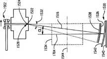
图15-19示出了一个实施例,其中辐射源平移,探测器阵列配合辐射源滚动。Figures 15-19 illustrate an embodiment in which the radiation source is translated and the detector array is rolled in conjunction with the radiation source.
图20和21示出了一个实施例,其中阳极包括曲面。Figures 20 and 21 show an embodiment in which the anode comprises a curved surface.
具体实施方式Detailed ways
以下内容一般性地涉及到一种计算机X线断层扫描摄影(CT)扫描仪,其中x射线管、源准直器和/或探测器阵列沿着z轴平移,和/或彼此独立地和/或相结合地和/或与固定支架/框架彼此独立地和/或相结合地沿着与z轴方向倾斜。应该理解为这种移动可以在扫描之前、过程中以及之后进行。在一个示例中,通过在扫描过程中动态地移动x射线管、辐射源准直器或探测器阵列中的一或多个,在不倾斜固定支架/框架的情况下就可以实现获得倾斜角,尽管该固定支架/框架也可以倾斜。The following generally relates to a computed tomography (CT) scanner in which the x-ray tube, source collimator, and/or detector array are translated along the z-axis, and/or independently of each other and/or Or in combination with and/or with the fixed bracket/frame independently of each other and/or in combination with the z-axis direction. It should be understood that such movement can occur before, during and after scanning. In one example, by dynamically moving one or more of the x-ray tube, radiation source collimator, or detector array during the scan, obtaining the tilt angle can be achieved without tilting the stationary support/frame, Although this fixed bracket/frame can also be tilted.
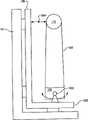
首先基准图1,CT扫描仪100包括固定支架部或框架102,其采用的固定方式是在扫描过程中保持静止。但是,该固定支架102可以配置为绕着倾斜轴104倾斜和/或者移动。扫描仪100还包括旋转支架部或转子106,其由固定支架102可旋转地支撑。旋转支架106围绕纵向轴或z轴110在检查区域108周围转动。Referring first to FIG. 1 , a
辐射源112,例如筒管或其它x射线管,放射出穿过检查区域108的辐射。辐射源准直器114校准放射出的辐射从而使大致为圆锥形、扇形、楔形或其它形态的辐射束穿过检查区域108。辐射源112和/或辐射源准直器114由围绕检查区域108的旋转支架106支撑并随之转动。辐射源112和辐射源准直器114通过支承或类似部件可移动地连接于旋转支架106上,下文将对此进行详述。在示出的例子中,辐射源112和辐射源准直器114机械地连接在一起。这样,本文中辐射源112和辐射源准直器114称作源/准直器112/114。A
辐射源定位系统116可选择地移动源/准直器112/114以在扫描前、扫描中和/或之后将源/准直器112/114定位到适当的位置。如图所示,扫描仪100包括两个辐射源定位系统116,分别在源/准直器112/114一侧。但是,在另外一个实施例中,扫描仪100包括一个或者超过两个的辐射源定位系统116。辐射源位置控制器118与辐射源定位系统116进行通讯并发出表示源/准直器112/114的所需移动的信号。如下文将进行详细描述的,这种移动可以包括源/准直器112/114在纵向轴110方向上的平移移动和/或源/准直器112/114在纵向轴110方向上的转动。Radiation
探测器阵列120设置在辐射源112的对面,在检查区域108相反侧。探测器阵列120包括一或多行沿横向方向延伸的辐射敏感像素。这些辐射敏感像素检测穿过检查区域108的辐射并且分别发出代表它们的信号。与辐射源112和准直器114类似,所显示的探测器阵列120由围绕检查区域108的旋转支架106支撑并随之转动。该探测器阵列120可移动地通过支承和/或枢轴可移动地连接于旋转支架106,下文将进行详细说明。The
当探测器阵列120配置为平移和/或旋转时,探测器定位系统122可选择地移动探测器阵列120,从而在扫描前、扫描中和/或之后将探测器阵列120定位到适当的位置。如图所示,扫描器100包括两个探测器阵列定位系统122,分别置于探测器阵列120的每侧。但是,与辐射源定位系统116类似,在另一个实施例中具有一或多于两个的探测器定位系统122。探测器位置控制器124与探测器定位系统122进行通讯并产生表示探测器阵列120移动的信号。需要理解的是,这种移动可以与源/准直器112/114的移动相配合地或者独立于源/准直器112/114的移动,包括在相同方向或者相反方向移动。在探测器阵列120配置为枢转的情况下,当源/准直器112/114平移时,探测器阵列120枢转。可以用反散射光栅(未示出)与探测器阵列120相连接。When the
重构器126对探测器阵列120产生的信号进行重构并产生表示检查区域108的体积图像数据。患者支撑装置(未示出),如躺椅,支撑在诊断区域108着的患者。该患者支撑装置配合旋转支架106的转动可沿着x、y和/或z轴方向上移动,从而利于获得椭圆、螺旋、轴向和/或其它期望的扫描轨迹。一般用途的计算系统用作操作员控制台128,其包括输入和人工可读输出设备,例如键盘和/或鼠标以及显示器和/或打印机。该计算系统中的软件通过基于操作者选择的扫描协议和/或其它方案发送用于源/准直器112/114和/或探测器阵列120的定位指令,从而控制系统100的运行。A
通过如上所述相对彼此可选择地移动源/准直器112/114和/或探测器阵列120,可以在不需要倾斜固定支架102的情况下获得例如椭圆轨迹等不同的倾斜轨迹。这样,扫描仪100可以配置为固定支架102不倾斜。在一个实例中,该特点消除了倾斜固定支架102所带来的前述的一或多个缺点。作为示例,如上述移动源/准直器112/114和/或探测器阵列120而非倾斜固定支架102可以消除在固定支架102与一或多个对象,如检查空间中的医疗设备和/或正在被扫描的病患之间潜在的碰撞。另外,节省掉用来倾斜固定支架102的机构也可以减小整个扫描仪重量、尺寸和/或成本。当然,当固定支架102配置为可以倾斜时,无论是否倾斜固定支架102都可以获得倾斜的轨迹。应该理解的是,一个专门的扫描协议可能需要移动源/准直器112/114、探测器阵列120或固定支架102中的一个,或者源/准直器112/114、探测器阵列120或固定支架102中的两个或多个。By selectively moving the source/
图2和图3展示了示例性的辐射源定位系统116。在示出的例子中,辐射源定位系统116包括细长的框架部202,其沿着横向轴线紧邻源/准直器112/114定位并沿着纵向轴110的方向延伸。框架部202包括第一主侧部或内侧部204,其面向源/准直器112/114,还包括相反的第二主侧部或外侧部206,其背向朝源/准直器112/114。该细长的框架部202还包括相反的第一和第二端部208和210。端部208通过类似于螺栓、螺钉、铆钉、胶水、粘着剂等的固定机构固定于旋转支架106上,从而将框架部202连接在旋转支架106上。在另一个实施例中,框架部202与旋转支架106通过磁力连接在一起。另一个实施例中,框架部202与旋转支架206是单一整体结构。2 and 3 illustrate an exemplary radiation
辐射源定位系统116还包括连接于框架部202的第一支承212。所显示的第一支承212是齿条和小齿轮型支承。但是,诸如矛齿轮(spear gear)、链条、皮带等的其它支承在此作为可选手段也可使用。第一支承212包括小齿轮216、218和220。小齿轮216一般是包括多个齿的环形齿轮,齿条218和220都是包括了多个齿的平面齿轮,其与小齿轮216的齿相啮合。齿条218和220置于框架部202相对的两侧,齿条218在内侧部204,齿条220在外侧部206。Radiation
齿轮216-220相对彼此设置成齿轮216-220中的任何一个的移动会使齿轮216和218的齿啮合以及使齿轮216和220的齿啮合,从而使三个齿轮216-220都动起来。在示出的例子中,其中一个齿条218(或者220)在一个方向上的平移使小齿轮216转动,从而使另一齿条220(或218)在相对于齿条218(或220)相反方向上平移。第一支承212连接于框架上从而使齿轮218和220在纵向轴110方向上平移。The gears 216-220 are arranged relative to each other such that movement of any one of the gears 216-220 engages the teeth of the
辐射源定位系统116的第二支承222包括线性支承。但是,该第二支承222可以替代地包括链条、皮带、导螺杆、滚珠丝杆等。第二支承222包括滑块224和导轨226。滑块224包括凹槽228。导轨226延伸框架部202的大体长度,与框架部202的内侧部204相连接,并且置于凹槽228中。滑块224可以沿着导轨226自由滑动或平移。支承222连接于框架并配置成滑块224在纵向方向平移。
辐射源定位系统116的第三支承230也包括线性支承,并且可以是上面提到的其它支承类型。第三支承230包括滑块232和导轨234。滑块232包括凹槽236。滑块234延伸框架部202的大体长度,与框架部202的外侧部206相连接,并且置于凹槽236中。滑块232可以沿着导轨234自由滑动或平移。支承230连接于框架并配置成滑块232在纵向方向平移。The
致动器238,例如是线性或其它类型的马达,连接于齿条218和辐射源112。致动器238通过连接于框架部202的内侧部204并在内侧部204与致动器238之间的磁性板240磁性地被致动。滑块224连接于准直器114。质量平衡块242连接于第一支承的齿条220和第三支承的滑块232,后文将进行详述。因此,源/准直器112/114与齿条220和滑块224一起在同一方向移动,质量平衡块242与齿条220和滑块232一起相对于框架部202沿着纵向方向在相反方向上移动。An
位置测量装置244,例如编码器或类似装置,连接于致动器238、滑块224和/或源/准直器112/114,并且确定源/准直器112/114相对于框架部202的绝对和/或相对位置。可移动的线缆臂246用来引导所有线缆、连接器和/或类似部件到辐射源112和/或准直器114。线缆臂246具有弹性,因此可以在源/准直器112/114移动时根据需要弯曲。可选地采用支撑结构以便利于支撑框架部202、源/准直器112/114、致动器238和/或其它部件。A
辐射源定位系统116一起沿着纵向移动源/准直器112/114,源/准直器112/114通过第一支承212沿纵向方向在相反方向移动质量平衡块242。与不使用质量平衡块242的系统相比,使用上述的质量平衡块可以减小旋转支架106受到的力。致动器238配置为通过共同的重心移动源/准直器112/114。每个质量平衡块242配置为相对于源/准直器112/114移动而共同重心248保持不变。支承230放置于质量平衡块242的重心250处,并且齿条220与支承230和重心250对齐放置。这样,就使支承230上的负载最小化。Together, the radiation
图4示出了示例性的探测器阵列定位系统122,其与前文讨论的辐射源定位系统116相类似。探测器阵列定位系统122包括细长的框架部402,其置于探测器阵列120下方从而使得探测器阵列120位于细长的框架部402和检查区域108之间。可选地,框架部402可以邻接探测器阵列120的端部设置。框架部402包括面向探测器阵列120的第一主侧部或内侧部404、背向探测器阵列120的相对的第二主侧部或外侧部406、通过前述的紧固机构固定在旋转支架106上的第一端(未示出)、和可以或者不可以固定到结构支撑上的第二端408。与框架部202类似,在另一个实施例中框架部402可以是旋转支架106的一部分。FIG. 4 illustrates an exemplary detector
探测器阵列定位系统122还包括连接于框架部402的第一支承410。第一支承410是类似于第一支承212的齿条和小齿轮型支承,其包括小齿轮412、齿条414和416。齿条414和416分别置于框架部402的相反侧,齿条414与第一内侧部404相邻,齿条416与外侧部406相邻。如源定位系统116所讨论的,齿轮412-416彼此设置成移动齿轮412-416中的任何一个就会导致齿轮412-416的其它两个移动。支承410与框架402相连接从而使齿条414和416沿着纵向方向以相反方向来回移动。The detector
第二和第三支承418和428与支承220和230相类似。第二支承418包括带有凹槽424的滑块422和连接于内侧部424的导轨426,导轨延伸框架部402的大体长度并且置于凹槽424中,使滑块422能沿着导轨426自由滑动或平移。第三支承428包括具有凹槽432的滑块430和连接于内侧部404的导轨434,导轨延伸框架部402的大体长度并且置于凹槽432中,使滑块430沿着导轨434自由滑动或平移。支承418和428连接于框架上并配置为滑块422和430在纵向轴110的方向上平移。Second and
致动器436,例如是线性或其它类型的马达,连接于齿条414和探测器阵列120。致动器436通过连接于框架部402的第一滑块404并位于框架部402和致动器436之间的磁性板438磁性地致动。滑块422也连接于探测器阵列120。质量平衡块440连接于轨迹414和第二滑块430上。因此,探测器阵列120与齿条416和滑块422在一个方向上平移而质量平衡块440与齿条416和滑块430相对于框架部402在相反方向上平移。位置测量装置442,例如是解码器或其它类似装置,测定探测器阵列120相对框架部402的绝对或相对位置。采用可移动的线缆臂444来引导所有线缆、连接器和/或类似部件到探测器阵列120。An
探测器定位系统122沿着纵向方向移动探测器阵列120,探测器阵列通过第一支承410沿着纵向方向在相反方向移动质量平衡块440。相对于没有质量平衡块440的系统,这样做减少了旋转支架106受到的力。通过将致动器436放置在探测器阵列120的下面,致动器吸力可以有助于探测器阵列120经受住离心力。The
可以预料到各种变化。Variations are contemplated.
作为举例的目的,上文提到的有关配置中辐射源112和准直器114是一起移动的。但在其它实施例中,辐射源112可以独立于准直器114倾斜。在该示例中,辐射源112和准直器114可以一起倾斜或者辐射源112倾斜而准直器114相对于辐射源112保持相对静止。For purposes of example, the configurations mentioned above relate to the configuration in which the
应该理解到,质量平衡块242和440可被直接驱动,例如在平衡块上安装线性马达。在一个例子中,这样可以减小支撑框架的力和齿轮负载。It should be appreciated that
在另一个实施例中,质量平衡块242和440被省掉了。In another embodiment, mass balances 242 and 440 are omitted.
在另一个实施例中,探测器定位系统122被省掉了。在该实施例中,源/准直器112/114可以如前文所述一样通过辐射源定位系统116移动。In another embodiment, the
在所描述的示例中,定位装置116和122的框架202和402的端部之一与旋转支架106相连。在另一个实施例中,旋转支架106包括第一板或背板,例如环形板502,以及第二板或前板,例如环形板504,如图5所示。在该实施例中,框架部202和402的端部506固定于背板502,而框架部202和402的端部508固定于前板504。在另一个实施例中,前板可以仅仅从框架部202延伸到框架部202和/或从框架部402延伸到框架部402,或者延伸小于整个环的距离。在另一个实施例中,前板可以包括一或多个其它形状的结构部件。在另一个实施例中,结构部件可以连接于框架部202的侧部204、侧部206、顶部和/或底部。In the depicted example, one of the ends of the
在所描述的示例中,源/准直器112/114和探测器阵列120是独立和单独的子系统,它们在不同的控制器118和124的控制下移动。图6示出了一个实施例,其中源/准直器112/114和探测器阵列120通过结构性连接部602物理连接在一起。该连接部602的第一端604物理连接于辐射源112和/或准直器114。第二端606物理连接于探测器阵列120。在该示例中,第二端606是支架608的一部分,该支架沿着探测器阵列120的底部延伸。此外,可以采用单一位置控制器610来驱动辐射源和探测器阵列定位系统116和122。In the depicted example, source/
在上文中,定位装置116和122平移源/准直器112/114和探测器阵列120。应该理解到,在其它实施例中源/准直器112/114和探测器阵列可附加地或可选地配置为相对于固定支架102倾斜。这有利于在扫描解剖体的期望区域时避免扫描解剖体的其它区域。图7a、7b、8a、8b、9a和9b中示出了在扫描内耳时为了避免辐射到视神经,在三个旋转位置下源/准直器112/114和探测器阵列120之间的旋转和平移的关系。当然,倾斜源/准直器112/114和探测器阵列120(平移或不平移源/准直器112/114和探测器阵列120)也能用于避免辐射到其它组织。In the above, the
图7a示出了扫描仪100的侧视图。在该示例中,旋转支架106成一个角度,在该角度,源/准直器112/114处于大概12点位置而探测器阵列120处于大概6点位置。当朝着该角度方向移动时,源/准直器112/114沿着纵向方向平移离开患者,而探测器阵列120沿着纵向方向朝向患者平移。如此,在该角度位置上辐射束成锐角从辐射源112引导到探测器阵列120,从而使穿过内耳的辐射束避开视神经。图7b示出了在朝向检查区域108的方向上辐射源112(作为成像系统710的一部分)的内视图。定位系统702平移并旋转源/准直器112/114和探测器阵列120。如图所示,定位系统702包括致动器7041和7042,如活塞或其它流体致动器,其用来驱动可转动地连接到枢轴7081和7082的引导臂7061和7062,所述枢轴连接于成像系统710的相对侧上,该成像系统共同地包括源/准直器112/114和探测器阵列120。在该示例中,引导臂7061和7062相类似地被驱动以平移源/准直器112/114。FIG. 7 a shows a side view of the
在图8a中,旋转支架106转动到一个角度,在此角度源/准直器112/114置于大概3点位置,探测器阵列120置于大概9点位置,而辐射束被导入纸页。在该角度位置,源/准直器112/114和探测器阵列120彼此之间沿着横向相互对齐。此外,倾斜旋转支架106,从而倾斜源/准直器112/114和探测器阵列120,导致辐射束以某个角度穿过检查区域,该角度下辐射束辐射到内耳而避开视神经。图8b示出了辐射源112的视图,其中通过移动引导臂7062比引导臂7061更大的程度使成像系统710倾斜。In Figure 8a, the
在图9a中,旋转支架106旋转到使源/准直器112/114位于大概6点位置,探测器阵列120位于大概12点位置。当朝向该角度位置移动时,源/准直器112/114沿着纵向轴的方向朝患者平移,而探测器阵列120沿着纵向轴的方向平移远离患者。如此,辐射束成角度从辐射源112引导到探测器阵列120,从而使穿过内耳的辐射束避开视神经。图9b示出了辐射源112的视图,其中引导臂7061和7062还是以类似的方式驱动,从而使成像系统710不发生倾斜。In Figure 9a, the
应该理解到,上文描述的是三个不同的角度位置下的急射(snap shot),当旋转支架106转动时,运动可以是连续的。还要注意到,旋转和线性致动器可以替代枢轴和第二线性致动器。还地,源/准直器112/114和探测器阵列120可以为了轴向自由度放置在线性支承上,随后可通过采用具有支承的平面进行引导。It should be understood that the above description is a snap shot at three different angular positions, and that the movement may be continuous as the
在另一个实施例中,探测器阵列120配置为围绕枢轴旋转而非如前文所述的平移或旋转。如图10中所示,其中探测器阵列120可围绕枢轴转动地连接于旋转支架106上。如图所示,源/准直器112/114和探测器阵列120通过例如在图6中说明的连接部件602连接在一起。旋转支架106包括突出部1000,其从旋转支架106沿着平行于纵向轴110的轴延伸。枢轴1002连接于突出部1000上。探测器阵列120可枢转地连接于枢轴1002。当源/准直器112/114沿着所述的纵轴在方向1004上平移时,探测器阵列120绕枢轴1002枢转。在另一个示例中,连接部602被去掉,采用单个的致动器来平移辐射源112和转动探测器阵列120。In another embodiment, the
在另一个实施例中,在不倾斜源/准直器112/114,并且不倾斜、枢转或平移探测器阵列120的情况下,通过平移源/准直器112/114电子地获得倾斜束几何形状。如此,通过平移源/准直器112/114可以获得处于期望倾斜角度的椭圆轨迹。在一个示例中,通过沿着纵向轴的方向平移源/准直器112/114超过40厘米(cm)获得了±30度的倾斜角度。该几何形状在图11和图12中示出。In another embodiment, the tilted beam is obtained electronically by translating the source/
参见图11,假设具有倾斜辐射束覆盖范围C的倾斜辐射束的中线与在半径R’处将要避免的宽度为D的未暴露对象在垂直方向上对齐的情况下(宽度C等于D),下面的约等式描述了倾斜束的几何形状:D≈R’.β=R’.(α-η)=C≈W.S/(S-R)以及τ≈β-(W/2)/(S-R),其中D是在半径R’处未暴露对象的宽度,C是束覆盖范围,β是圆锥角度,α是阳极角,η是横倾斜角,W是在半径R处倾斜体积宽度,S是辐射源半径,τ是倾斜角。当α=8°,η=4°,R=12.5cm,R’=10cm,S=57cm时,β=4°,D=C≈0.7cm,τ≈3.6°,W≈0.55cm,当α=12°,η=4°,R=12.5cm,R’=10cm,S=57cm时:β=8°,D=C≈1.4cm,τ≈7.3°,W≈1.1cm。Referring to FIG. 11 , assuming that the centerline of the oblique radiation beam with oblique radiation beam coverage C is vertically aligned with an unexposed object of width D to be avoided at radius R' (width C equals D), the following The approximate equation of describes the geometry of the oblique beam: D≈R'.β=R'.(α-η)=C≈W.S/(S-R) and τ≈β-(W/2)/(S-R), where D is the width of the unexposed object at radius R', C is the beam coverage, β is the cone angle, α is the anode angle, η is the transverse tilt angle, W is the tilt volume width at radius R, and S is the radiation source Radius, τ is the tilt angle. When α=8°, η=4°, R=12.5cm, R'=10cm, S=57cm, β=4°, D=C≈0.7cm, τ≈3.6°, W≈0.55cm, when α =12°, η=4°, R=12.5cm, R'=10cm, S=57cm: β=8°, D=C≈1.4cm, τ≈7.3°, W≈1.1cm.
基准图12,假设宽度C≈β.S的倾斜束的远边缘与宽度为D的未暴露对象的远边缘垂直对齐,下面的约等式描述了倾斜束的几何形状:D≈R’.β=R’.(α-η),W≈C.(S-R)/S以及τ≈β/2。当α=8°,η=4°,R=12.5cm,R’=10cm,S=57cm时,β=4°,C≈4cm,D≈0.7cm,τ≈2°,W≈3.1cm,当α=12°,η=4°,R=12.5cm,R’=10cm,S=57cm时:β=8°,C≈8cm,D≈1.4cm;τ≈4°,W≈6.2cm。Referring to Figure 12, assuming that the far edge of an oblique beam of width C ≈ β.S is vertically aligned with the far edge of an unexposed object of width D, the following approximate equation describes the geometry of the oblique beam: D ≈ R'.β =R'.(α-η), W≈C.(S-R)/S and τ≈β/2. When α=8°, η=4°, R=12.5cm, R'=10cm, S=57cm, β=4°, C≈4cm, D≈0.7cm, τ≈2°, W≈3.1cm, When α=12°, η=4°, R=12.5cm, R'=10cm, S=57cm: β=8°, C≈8cm, D≈1.4cm; τ≈4°, W≈6.2cm.
电子倾斜对于更大的圆锥角更加有用,在此情况下可以避免较大对象的暴露(对于12°阳极角大于1.4cm)。不需要移动探测器并且仍然可以使用二维防散射光栅。需要将准直器沿着与辐射源相反的方向移动和旋转,以保持辐射束与倾斜面对齐。如果辐射源和探测器在相反方向上移动时都被倾斜,就可以获得更大的倾斜角(例如对于辐射源移动32cm可获得15.7度的角度)。但是,仍然必须转动准直器以保持辐射束与成90°的倾斜平面对齐。Electron tilting is more useful for larger cone angles, where exposure of larger objects can be avoided (greater than 1.4 cm for a 12° anode angle). There is no need to move the detector and two-dimensional anti-scatter gratings can still be used. The collimator needs to be moved and rotated in the direction opposite to the radiation source to keep the radiation beam aligned with the inclined plane. Larger tilt angles can be obtained if both the radiation source and the detector are tilted while moving in opposite directions (for example an angle of 15.7 degrees is obtained for a radiation source movement of 32 cm). However, the collimator must still be turned to keep the radiation beam aligned with the 90° inclined plane.
在上述示例中,旋转支架106用作位置测量系统的基准物。因此,测量过程会有各种不同的误差。例如,由于不平衡或者反作用力引起的转子的震动导致转子扭曲、例如重力或离心力引起的机械应力、还有转子的旋转运动的有限准确度(自由度的叠加)都会引起误差。在图13示出的实施例中,扫描仪100包括单独的基准框架或测量框架1302,该框架与扫描仪100的旋转支架106隔离但是与其接近。在该实施例中,总测量环路每个阶段包括两个传感器:一套第一或本地传感器1304,其用来测量辐射源112和探测器阵列120相对于旋转支架106的位移,以及第二或基准传感器1306,其用来测量旋转支架106相对于测量框架1302的位移。在一个示例中,该套传感器1304包括成不同角度设置在圆上的一组三个传感器。为了设备内校准,基准传感器中的一个需要由成不同角度(具有具体间隔)设置在圆上的一组三个传感器替代。In the above example, the
如此处所描述的,x射线管112、辐射源准直器114和/或探测器阵列120以彼此独立地和/或彼此相连的方式、和/或与固定支架/框架彼此独立地和/或彼此相连的方式沿z轴平移和/或在z轴方向上倾斜。应该理解到,这些部件中的每个可以与其它一或多个部件独立地移动和/或相配合移动。如此,在一个示例中,在无需倾斜固定支架102的情况下,辐射源112和探测器阵列120平移,准直器叶片配合移动以实现有效的倾斜。在另一个示例中,由于在无需倾斜固定支架102的情况下探测器阵列120完成了有效的倾斜,因此当辐射源112和准直器114在相反方向平移时,辐射源112能够具有较大的圆锥角。在该示例中,可以使用一维的防散射光栅。准直器114也可以随辐射源112倾斜。通过适当地倾斜探测器阵列120,可以使用二维防散射光栅。As described herein, the
在另一个示例中,辐射源112倾斜并平移,准直器114与辐射源112一起平移,探测器阵列120在相反方向上平移以实现有效的倾斜而无需倾斜固定支架102。在该示例中,可以使用一维的防散射光栅。通过适当地倾斜探测器阵列120,可以使用二维防散射光栅。准直器114也可以随辐射源112一起倾斜。在另一个示例中,辐射源112、准直器114和探测器阵列120都在一个共同框架上沿着中轴线相配合地倾斜,从而在无需倾斜固定支架102的情况下实现有效的倾斜。在该示例中,可以使用二维防散射光栅。还可以考虑将辐射源112、准直器114和/或探测器阵列120的其他移动组合。运行过程结合图14进行说明。应该理解到下述动作的顺序仅作示例作用而不作为限制。In another example, the
在1402,选择包括倾斜角轨迹的扫描协议。At 1402, a scan protocol including a tilt angle trajectory is selected.
在1404,如此处所描述的,在不倾斜固定支架102的情况下,源/准直器112/114和/或探测器阵列120沿着纵向轴平移和/或旋转。At 1404, the source/
与此同时,在1406,开始执行扫描。At the same time, at 1406, a scan is performed.
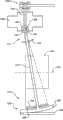
参见图15和16,辐射源支架1502通过一或多个支承1506可移动地连接于旋转支架1504,所述支承可以包括线性滑块、球和/或其它前面提及到的支承以及其它支承。辐射源支架1502通过支承1506沿着旋转轴1544在z方向上平移。辐射源1508连接于辐射源支架1502并且随之一起平移。辐射源支架驱动设备1510在z方向上驱动辐射源支架1502。该驱动设备1510可以包括驱动导螺杆、滚珠丝杠、链条、矛齿轮、皮带等的马达或类似装置,它驱动辐射源支架1502。控制器1512根据扫描协议或其它协议控制驱动设备1510。Referring to Figures 15 and 16,
机械连接部件或框架1516连接辐射源1508和探测器阵列1536。框架1516的第一端1514可枢转地连接于辐射源1508。在示出的实施例中,辐射源1508包括两个连接部件1526,框架1516的第一端1514包括穿过连接部件1526延伸的两个枢轴1522。两个枢轴1522配置为围绕假想枢轴线1524转动,该假想枢轴线穿过连接部件1526的中心区域延伸并与x轴平行,与z轴相垂直,并与辐射源1508的焦点1528相交。在其它实施例中,该系统可以包括更少或更多的枢轴1522和/或连接部件1526。A mechanical link or
框架1516的第二端1518在检查区域1520相对侧辐射源1508的对面可移动地连接于旋转支架1504。框架1516的第二端1518通过支承连接于旋转支架1504。支承1530的第一部分1540连接于旋转支架1504并在z方向上延伸。所示出的位于探测器阵列1536下方的第一部分1540的位置仅作为示例,其可以放置在其它位置,例如在探测器阵列1536的侧面或者上面,以及在视场1534之外。此外,在其它实施例中该系统可以包括更少或更多的支承1530。A
支承1530的第二部分1542连接于框架1516的第二端1518或者作为它的一部分,该第二部分所处位置与第一部分1540在旋转支架1504上的位置相一致。如图16所示,第二部分1524呈弧形并可以在支承1530的第一部分1540上滚转(或滚动)。由于框架1516连接于辐射源1508,第二部分1542与辐射源支架1502沿旋转轴线1544的平移移动相配合滚转。在一个示例中,部分1540和1542中的至少一个包括与部分1540和1542中的另一个的配合部位相啮合的齿轮或轮圈。该配合部位可以包括齿并且在齿之间具有凹槽,或者替代地包括具有能容纳齿轮的齿的凹部。A
位于检查区域1520的相对侧上辐射源1508对面的探测器阵列1536连接于框架1616的第二端1518。探测器阵列1536包括用来探测穿过检查区域1520的辐射并产生表示检测到的辐射的信号的的至少一个探测器像素。防散射光栅1538减弱和基本上阻止散射辐射入射到探测器阵列1536。该防散射光栅1538可以是一维或二维防散射光栅。该防散射光栅1538可以被省掉。A
将辐射源1504发出的辐射沿z轴校准的辐射源准直器1532在辐射源1508与视场1534之间固定到框架1516上。如在本文所描述的,可采用一或多个平衡重(为清楚目的未示出)来平衡辐射源支架1502、辐射源1508、框架1516、准直器1532、探测器1536和/或一个或多个其它移动部件的质量变化。A
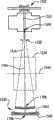
下面结合图17-19对运行过程进行说明。图17中,辐射源支架1502位于行程的大体中心位置1702。在该位置,框架1516从辐射源1508沿假想线1704延伸,该假想线垂直于旋转轴1602的中心区域。准直器1532处于其孔径相对于假想线1704大体对称的位置,支承1530的第二部分1542的中心区域1706位于支承的第一部分1540上并与假想线1704对齐,探测器阵列1536的中心区域1708被聚焦在焦点1528处。The operation process will be described below in conjunction with FIGS. 17-19. In FIG. 17, the
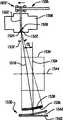
图18中,辐射源支架1502位于行程的一端1802。当辐射源支架1502平移到该位置,辐射源1508与其一起平移。与上述平移相配合,框架1516的枢轴1522围绕枢转轴线1524枢转,支承1530的第二部分1542在第一部分1540上滚转,并且框架1516从焦点1528处以相对于假想线1704成一个角度延伸,该角度幅值从0度增加到大约α度。准直器1532同样也平移,探测器阵列1536的中心区域1708保持聚焦在焦点1528处。In FIG. 18, the
图19中,辐射源支架1502位于行程的另一端1902。当辐射源支架1502平移到该位置时,枢轴1522围绕枢转轴线1524枢转,支承1530的第二部分1542沿与图18中相反方向滚转。类似地,框架1516从焦点1528以相对于假想线1704成一个角度延伸,该角度幅值从0度增加到大约α度。同样,准直器1532也平移,探测器阵列1536的中心区域保持聚焦在焦点1528处。In FIG. 19 , the
在另外一个实施例中,框架1516被去掉,探测器支架驱动设备以与支承的第二部分1542的滚转类似的方式与辐射源支架驱动设备1510相配合地驱动或滚转保持探测器阵列1536的探测器支架。In another embodiment, the
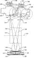
图20和图21描述了图15-19的实施例的变形。在该变形中,辐射源支架1502倾斜/向下地平移。Figures 20 and 21 depict variations on the embodiment of Figures 15-19. In this variation, the
图20示出了辐射源支架1502在两个端部1802和1902的叠加图。与图17-19一样,当辐射源支架1502位于行程中间位置时,框架1516沿着垂直于旋转轴线1602的中心区域的假想线延伸,准直器1532处于其孔径相对于假想线大体对称的位置,支承1530的第二部分1542的中心区域位于支承的第一部分1540上并与假想线对齐,探测器阵列1536的中心区域被聚焦在焦点1528处。FIG. 20 shows an overlay of
当辐射源支架1502平移到位置1802和1902时,辐射源1508沿着倾斜向下方向平移,枢轴1522围绕枢转轴线1524枢转,第二部分1542配合平移滚转,框架1516从焦点1528相对于假想线成角度延伸,准直器1532平移,探测器阵列1536的中心区域保持聚焦在焦点1528处。As
这种实施例适于与具有可变阳极角的旋转阳极型辐射源配合使用,所述可变阳极角指辐射束与阳极表面之间的角度,当辐射源支架1502平移时,辐射源1508倾斜和向下的平移移动可以用来补偿x射线源内焦点1528位置的变化,从而保持移动焦点1528与旋转轴线1544之间的距离恒定。相对于阳极角不可变的配置,这种辐射源可以用来提供更小的阳极角、增大的分辨率和增大的最大功率。图21示出了具有可变阳极角的示例性辐射阳极2102。Such an embodiment is suitable for use with a rotating anode type radiation source having a variable anode angle, the angle between the radiation beam and the anode surface, the
图21中,旋转阳极2102的截面具有例如具有适当曲率半径的凸形的弯曲部分2104,所述曲率半径例如是在一(1)到二十(20)厘米(cm)的数量级。电子束2106在阳极2102上对应于探测器阵列1536的焦点位置的位置被导引(静电或电磁地),从而在与探测器阵列1536的焦点位置相对应的位置产生焦点1528。在图21中,辐射源1508位于行程的中间位置1702,探测器阵列1536位于辐射源1528下方的中间位置,圆锥辐射束2106的范围2104相对于垂直于探测器阵列1536从焦点1528延伸的中心线对称。在行程的其它位置处,电子束2106在阳极2102上更高或更低(可选地)但仍然对应于探测器阵列1536的焦点位置的位置被导引,从而在其它位置处产生焦点1528。In FIG. 21 , the cross-section of
框架1516的枢轴1522在与焦点1528偏移并与曲线中点重合的位置2108处可枢转地连接到辐射源1508。因此,焦点1528与位置2108之间的距离与曲率的半径重合或者大约相等。(可选地,此句可以删掉)焦点1528和点2112之间的距离限定了角度β,该角度是有效阳极角,或者是从焦点1528处垂直延伸的假想线2102和在阳极表面经过焦点1528相切地延伸的假想线2104之间的角度。该角度代表圆锥辐射束的平均出射角并与圆锥形阳极表面的阳极角相对应。
回到图20,当支架1502沿着倾斜向下方向2102平移时,辐射源1508沿着倾斜向下方向2102平移并且电子束2106重新聚焦在阳极2102上,焦点1528沿着平行于旋转轴线1524的直线2104平移。这样,在一个示例中,当辐射源支架1502平移时,辐射源1508沿着倾斜向下方向的平移可以用来补偿移动的焦点1528和旋转轴线1524之间距离的任何变化。这样,可以提供焦点1528和在需要时对所有或部分的辐射源位置都保持基本恒定的有效阳极角β。Returning to FIG. 20 , as the
本发明参照不同的实施例在文中进行了描述。通过阅读本文可以知晓还可以作出其它的修改和改变。本发明应包括后附的权利要求或者等效的主题所覆盖的范围内所有修改或变化。The invention has been described herein with reference to various embodiments. It will be apparent from reading this that other modifications and changes can be made. The present invention shall include all modifications or changes within the scope covered by the appended claims or equivalent subject matter.
Claims (13)
Translated fromChineseApplications Claiming Priority (5)
| Application Number | Priority Date | Filing Date | Title |
|---|---|---|---|
| US4944108P | 2008-05-01 | 2008-05-01 | |
| US61/049,441 | 2008-05-01 | ||
| US10115908P | 2008-09-30 | 2008-09-30 | |
| US61/101,159 | 2008-09-30 | ||
| PCT/IB2009/051764WO2009133530A1 (en) | 2008-05-01 | 2009-04-30 | Source and/or detector positioning system |
Publications (2)
| Publication Number | Publication Date |
|---|---|
| CN102014755A CN102014755A (en) | 2011-04-13 |
| CN102014755Btrue CN102014755B (en) | 2013-02-13 |
Family
ID=40902609
Family Applications (1)
| Application Number | Title | Priority Date | Filing Date |
|---|---|---|---|
| CN2009801151839AExpired - Fee RelatedCN102014755B (en) | 2008-05-01 | 2009-04-30 | Radiation source and/or detector positioning system |
Country Status (5)
| Country | Link |
|---|---|
| US (1) | US8693621B2 (en) |
| EP (1) | EP2271263B1 (en) |
| CN (1) | CN102014755B (en) |
| AT (1) | ATE535191T1 (en) |
| WO (1) | WO2009133530A1 (en) |
Families Citing this family (38)
| Publication number | Priority date | Publication date | Assignee | Title |
|---|---|---|---|---|
| EP2279494B1 (en)* | 2008-05-21 | 2016-11-02 | Koninklijke Philips N.V. | Dynamic adjustable source collimation during fly-by scanning |
| CN102068266A (en)* | 2010-09-29 | 2011-05-25 | 深圳市蓝韵实业有限公司 | Guide rail and rack integrated drive structure of digital X-ray machine |
| CN102814005A (en)* | 2011-05-13 | 2012-12-12 | 通用电气公司 | Method for providing light uniform distribution in phototherapy apparatus |
| BR112014002780A2 (en)* | 2011-08-10 | 2017-02-21 | Koninklijke Philips Nv | imaging system and method |
| US9125572B2 (en) | 2012-06-22 | 2015-09-08 | University Of Utah Research Foundation | Grated collimation system for computed tomography |
| US20140085641A1 (en)* | 2012-09-27 | 2014-03-27 | Electronics And Telecommunications Research Institute | Method and apparatus for recognizing location of piled objects |
| US9277900B2 (en)* | 2013-01-07 | 2016-03-08 | Samsung Electronics Co., Ltd. | X-ray imaging apparatus |
| US9402591B2 (en)* | 2013-03-15 | 2016-08-02 | Toshiba Medical Systems Corporation | Dynamic alignment of sparse photon counting detectors |
| US9089266B2 (en)* | 2013-04-19 | 2015-07-28 | Kabushiki Kaisha Toshiba | Tilted detector array for medical imaging systems including computed tomography |
| US9044151B2 (en)* | 2013-06-12 | 2015-06-02 | General Electric Company | Straddle mount detector assembly |
| CN105612416B (en)* | 2013-07-25 | 2019-01-01 | 模拟技术公司 | The generation of the diffractive features of article in object |
| US9808211B2 (en)* | 2013-11-12 | 2017-11-07 | Carestream Health, Inc. | Head and neck imager |
| US10791999B2 (en)* | 2014-02-04 | 2020-10-06 | General Electric Company | Interface for gantry and component |
| KR101609932B1 (en)* | 2014-07-02 | 2016-04-06 | (의료)길의료재단 | Curved movable beam stop array and CBCT comprising thereof |
| US10039505B2 (en)* | 2014-07-22 | 2018-08-07 | Samsung Electronics Co., Ltd. | Anatomical imaging system having fixed gantry and rotating disc, with adjustable angle of tilt and increased structural integrity, and with improved power transmission and position sensing |
| CN104316547B (en)* | 2014-11-05 | 2017-04-19 | 同方威视技术股份有限公司 | Rotary arc detector box for X-ray testing device |
| US10016171B2 (en)* | 2014-11-12 | 2018-07-10 | Epica International, Inc. | Radiological imaging device with improved functionality |
| US10762998B2 (en) | 2014-11-20 | 2020-09-01 | Viken Detection Corporation | X-ray scanning system |
| KR102340197B1 (en)* | 2015-02-03 | 2021-12-16 | 삼성전자주식회사 | X ray apparatus and method of oprating the same |
| US11259762B2 (en)* | 2015-12-25 | 2022-03-01 | Shanghai United Imaging Healthcare Co., Ltd. | Apparatus, system and method for radiation based imaging |
| EP3518766A1 (en)* | 2016-09-29 | 2019-08-07 | Analogic Corporation | Rotating structure for radiation imaging modalities |
| US10770195B2 (en) | 2017-04-05 | 2020-09-08 | Viken Detection Corporation | X-ray chopper wheel assembly |
| WO2018227523A1 (en)* | 2017-06-16 | 2018-12-20 | Shanghai United Imaging Healthcare Co., Ltd. | Systems and methods for image data processing in computerized tomography |
| US11382574B2 (en) | 2017-11-06 | 2022-07-12 | Rensselaer Polytechnic Institute | Stationary in-vivo grating-enabled micro-CT architecture (sigma) |
| CN108022637B (en)* | 2017-11-27 | 2020-10-23 | 上海联影医疗科技有限公司 | Medical imaging device adaptive method and adaptive medical imaging system |
| CN108226195B (en)* | 2017-12-28 | 2023-10-13 | 清华大学 | CT inspection system and CT imaging method |
| DE102018100228B3 (en)* | 2018-01-08 | 2019-05-09 | Framatome Gmbh | Measuring table for a ball measuring system of a nuclear reactor |
| CN109901213B (en)* | 2019-03-05 | 2022-06-07 | 中国辐射防护研究院 | Method and system for generating gamma scanning scheme based on Router grid |
| CN111281407B (en) | 2020-02-17 | 2023-09-29 | 京东方科技集团股份有限公司 | C-shaped arm X-ray equipment |
| US11681068B2 (en) | 2020-06-02 | 2023-06-20 | Viken Detection Corporation | X-ray imaging apparatus and method |
| CN115436989B (en)* | 2021-06-04 | 2025-08-29 | 同方威视技术股份有限公司 | Beam distribution detection device and beam distribution detection method |
| CN115598719B (en)* | 2021-07-07 | 2024-06-07 | 同方威视技术股份有限公司 | Inspection system and method |
| CN115097535B (en)* | 2021-07-07 | 2024-09-20 | 清华大学 | Inspection system and method |
| CN115598715B (en)* | 2021-07-07 | 2024-10-15 | 同方威视技术股份有限公司 | Inspection system and method |
| CN115113287B (en)* | 2021-07-07 | 2024-09-20 | 清华大学 | Inspection system and method |
| WO2023123301A1 (en)* | 2021-12-31 | 2023-07-06 | Shenzhen Xpectvision Technology Co., Ltd. | Imaging systems with rotating image sensors |
| EP4551976A2 (en) | 2022-07-07 | 2025-05-14 | Viken Detection Corporation | Rotating hoop chopper wheel for x-ray imagers |
| CN116773565B (en)* | 2023-06-12 | 2024-09-24 | 同方威视技术股份有限公司 | Detection device and detection method for detecting battery cell |
Family Cites Families (34)
| Publication number | Priority date | Publication date | Assignee | Title |
|---|---|---|---|---|
| US4045672A (en)* | 1975-09-11 | 1977-08-30 | Nihon Denshi Kabushiki Kaisha | Apparatus for tomography comprising a pin hole for forming a microbeam of x-rays |
| US4112303A (en)* | 1977-02-25 | 1978-09-05 | General Electric Company | Gantry for computed tomography |
| US4093863A (en)* | 1977-03-03 | 1978-06-06 | Artronix, Inc. | Tomographic apparatus |
| US4817119A (en)* | 1977-08-25 | 1989-03-28 | National Biomedical Research Foundation | Method and apparatus for computerized tomographic scanning with plural intersecting sets of parallel radiation beams |
| US5448607A (en)* | 1994-02-08 | 1995-09-05 | Analogic Corporation | X-ray tomography system with gantry pivot and translation control |
| JPH10118058A (en)* | 1996-10-23 | 1998-05-12 | Hitachi Medical Corp | X-ray ct apparatus |
| US5802134A (en)* | 1997-04-09 | 1998-09-01 | Analogic Corporation | Nutating slice CT image reconstruction apparatus and method |
| JP2000197627A (en)* | 1999-01-05 | 2000-07-18 | Hitachi Medical Corp | X-ray ct device |
| DE19928738C2 (en)* | 1999-06-23 | 2003-04-24 | Siemens Ag | Computer tomography (CT) device for generating sectional images of slices of an examination object inclined to the longitudinal axis of a storage device |
| IL148871A0 (en)* | 2000-09-28 | 2002-09-12 | Philips Medical Systems Techno | Ct scanner for time-coherent large coverage |
| US6704392B2 (en)* | 2001-07-03 | 2004-03-09 | Ge Medical Systems Global Technology Company, Llc | X-ray tube and method having tilted rotation axis |
| JP4175791B2 (en)* | 2001-08-20 | 2008-11-05 | ジーイー・メディカル・システムズ・グローバル・テクノロジー・カンパニー・エルエルシー | Image generation method and X-ray CT apparatus |
| US6683935B2 (en)* | 2001-09-28 | 2004-01-27 | Bio-Imaging Research, Inc. | Computed tomography with virtual tilt and angulation |
| AU2003224711A1 (en)* | 2002-03-19 | 2003-10-08 | Breakaway Imaging, Llc | Computer tomograph with a detector following the movement of a pivotable x-ray source |
| US6751283B2 (en)* | 2002-08-06 | 2004-06-15 | Koninklijke Philips Electronics, N.V. | Reconstruction method for tilted-gantry computed tomography |
| ATE471110T1 (en)* | 2002-08-21 | 2010-07-15 | Breakaway Imaging Llc | SCAFFOLD POSITIONING DEVICE FOR X-RAY EQUIPMENT |
| CN1672039A (en)* | 2002-09-04 | 2005-09-21 | 皇家飞利浦电子股份有限公司 | Anti-scatter X-ray shielding for CT scanners |
| US6862337B2 (en)* | 2003-06-25 | 2005-03-01 | General Electric Company | Linear track based digital tomosynthesis system and method |
| US20050100126A1 (en)* | 2003-11-07 | 2005-05-12 | Mistretta Charles A. | Computed tomography with z-axis scanning |
| US7235790B2 (en)* | 2004-02-17 | 2007-06-26 | Ge Medical Systems Global Technology Company, Llc | Methods and apparatus for radiation detection |
| US7248666B2 (en)* | 2004-05-24 | 2007-07-24 | Kabushiki Kaisha Toshiba | X-ray computed tomography apparatus |
| CN2796650Y (en)* | 2005-03-31 | 2006-07-19 | 西门子(中国)有限公司 | Computer tomography system capable of regulating distance of focus to detector |
| DE102006036327A1 (en)* | 2006-08-03 | 2008-02-14 | Siemens Ag | Method for providing 3D image data and system for taking X-ray images |
| WO2008018510A1 (en)* | 2006-08-08 | 2008-02-14 | Shimadzu Corporation | Radiation imaging device |
| EP2057603A1 (en) | 2006-08-22 | 2009-05-13 | Koninklijke Philips Electronics N.V. | Computed tomography reconstruction for two tilted circles |
| WO2008026153A2 (en) | 2006-08-31 | 2008-03-06 | Koninklijke Philips Electronics N.V. | Imaging system |
| US7983385B2 (en) | 2006-09-29 | 2011-07-19 | Koninklijke Philips Electronics N.V. | Fly-by scanning |
| US7548604B2 (en)* | 2007-01-04 | 2009-06-16 | General Electric Company | Method and apparatus for reduction of metal artifacts in CT imaging |
| US7453978B1 (en)* | 2007-06-25 | 2008-11-18 | University Of Tennessee Research Foundation | Variable resolution x-ray CT detector with multi-axis tilt |
| WO2009022408A1 (en)* | 2007-08-13 | 2009-02-19 | Shimadzu Corporation | Radiation imaging apparatus |
| JP2011502567A (en)* | 2007-11-06 | 2011-01-27 | コーニンクレッカ フィリップス エレクトロニクス エヌ ヴィ | Nuclear medicine SPECT-CT apparatus with integrated asymmetric flat panel cone beam CT and SPECT system |
| US8520974B2 (en)* | 2008-01-11 | 2013-08-27 | Shimadzu Corporation | Image processing method, an apparatus therefor and a tomographic apparatus for removing artifacts from a sectional image |
| US8571172B2 (en)* | 2008-04-14 | 2013-10-29 | Arineta Ltd. | CT cone beam scanner |
| US8401144B2 (en)* | 2008-08-07 | 2013-03-19 | Koninklijke Philips Electronics N.V. | Method and apparatus for correcting artifacts in circular CT scans |
- 2009
- 2009-04-30CNCN2009801151839Apatent/CN102014755B/ennot_activeExpired - Fee Related
- 2009-04-30WOPCT/IB2009/051764patent/WO2009133530A1/enactiveApplication Filing
- 2009-04-30USUS12/990,278patent/US8693621B2/enactiveActive
- 2009-04-30ATAT09738543Tpatent/ATE535191T1/enactive
- 2009-04-30EPEP09738543Apatent/EP2271263B1/ennot_activeNot-in-force
Also Published As
| Publication number | Publication date |
|---|---|
| CN102014755A (en) | 2011-04-13 |
| ATE535191T1 (en) | 2011-12-15 |
| US20110058644A1 (en) | 2011-03-10 |
| EP2271263A1 (en) | 2011-01-12 |
| WO2009133530A1 (en) | 2009-11-05 |
| US8693621B2 (en) | 2014-04-08 |
| EP2271263B1 (en) | 2011-11-30 |
Similar Documents
| Publication | Publication Date | Title |
|---|---|---|
| CN102014755B (en) | Radiation source and/or detector positioning system | |
| US7864918B2 (en) | X-ray machine for breast examination having a gantry incorporated in a patient table | |
| JP7487172B2 (en) | Apparatus for digital imaging of the head region of a patient - Patent application | |
| US6882700B2 (en) | Tomosynthesis X-ray mammogram system and method with automatic drive system | |
| US8678647B2 (en) | Systems and methods for imaging large field-of-view objects | |
| US6452998B2 (en) | Tiltable gantry for x-ray tomography system | |
| EP2503942B1 (en) | Computed tomography apparatus for odontology | |
| US20060029181A1 (en) | Upright ct scanner | |
| US20060291618A1 (en) | Tomographic mammography method | |
| JP6033562B2 (en) | Arc medical imaging system | |
| CN1585621A (en) | 3d reconstruction system and method utilizing a variable x-ray source to image distance | |
| JP2008528985A (en) | Tomographic machine with variable imaging geometry | |
| EP3097854B1 (en) | Ct photographic device | |
| KR20110000635A (en) | Adjustable scanner | |
| US20230148979A1 (en) | X-ray imaging arrangement | |
| JP4922586B2 (en) | Equipment for radiation projection tomography | |
| US11937961B2 (en) | Universal positioning system for X-ray imaging system | |
| US12016708B2 (en) | X-ray imaging apparatus | |
| JP5248044B2 (en) | Table system and X-ray CT apparatus | |
| CN223054473U (en) | Medical radiation detection equipment | |
| CN120661176A (en) | X-ray scanning system | |
| CN120594568A (en) | Imaging system |
Legal Events
| Date | Code | Title | Description |
|---|---|---|---|
| C06 | Publication | ||
| PB01 | Publication | ||
| C10 | Entry into substantive examination | ||
| SE01 | Entry into force of request for substantive examination | ||
| C14 | Grant of patent or utility model | ||
| GR01 | Patent grant | ||
| CF01 | Termination of patent right due to non-payment of annual fee | Granted publication date:20130213 | |
| CF01 | Termination of patent right due to non-payment of annual fee |