CN102014750A - flash flow blood collection needle - Google Patents
flash flow blood collection needleDownload PDFInfo
- Publication number
- CN102014750A CN102014750ACN2008801287783ACN200880128778ACN102014750ACN 102014750 ACN102014750 ACN 102014750ACN 2008801287783 ACN2008801287783 ACN 2008801287783ACN 200880128778 ACN200880128778 ACN 200880128778ACN 102014750 ACN102014750 ACN 102014750A
- Authority
- CN
- China
- Prior art keywords
- chamber
- needle assembly
- patient
- housing
- blood
- Prior art date
- Legal status (The legal status is an assumption and is not a legal conclusion. Google has not performed a legal analysis and makes no representation as to the accuracy of the status listed.)
- Granted
Links
Images


Classifications
- A—HUMAN NECESSITIES
- A61—MEDICAL OR VETERINARY SCIENCE; HYGIENE
- A61B—DIAGNOSIS; SURGERY; IDENTIFICATION
- A61B5/00—Measuring for diagnostic purposes; Identification of persons
- A61B5/15—Devices for taking samples of blood
- A61B5/150007—Details
- A61B5/150015—Source of blood
- A61B5/15003—Source of blood for venous or arterial blood
- A—HUMAN NECESSITIES
- A61—MEDICAL OR VETERINARY SCIENCE; HYGIENE
- A61B—DIAGNOSIS; SURGERY; IDENTIFICATION
- A61B5/00—Measuring for diagnostic purposes; Identification of persons
- A61B5/14—Devices for taking samples of blood ; Measuring characteristics of blood in vivo, e.g. gas concentration within the blood, pH-value of blood
- A61B5/1405—Devices for taking blood samples
- A61B5/1422—Devices for taking blood samples provided with indicating means, e.g. for vein entry
- A—HUMAN NECESSITIES
- A61—MEDICAL OR VETERINARY SCIENCE; HYGIENE
- A61B—DIAGNOSIS; SURGERY; IDENTIFICATION
- A61B5/00—Measuring for diagnostic purposes; Identification of persons
- A61B5/15—Devices for taking samples of blood
- A61B5/150007—Details
- A61B5/150206—Construction or design features not otherwise provided for; manufacturing or production; packages; sterilisation of piercing element, piercing device or sampling device
- A61B5/150213—Venting means
- A—HUMAN NECESSITIES
- A61—MEDICAL OR VETERINARY SCIENCE; HYGIENE
- A61B—DIAGNOSIS; SURGERY; IDENTIFICATION
- A61B5/00—Measuring for diagnostic purposes; Identification of persons
- A61B5/15—Devices for taking samples of blood
- A61B5/150007—Details
- A61B5/150374—Details of piercing elements or protective means for preventing accidental injuries by such piercing elements
- A61B5/150381—Design of piercing elements
- A61B5/150389—Hollow piercing elements, e.g. canulas, needles, for piercing the skin
- A—HUMAN NECESSITIES
- A61—MEDICAL OR VETERINARY SCIENCE; HYGIENE
- A61B—DIAGNOSIS; SURGERY; IDENTIFICATION
- A61B5/00—Measuring for diagnostic purposes; Identification of persons
- A61B5/15—Devices for taking samples of blood
- A61B5/150007—Details
- A61B5/150374—Details of piercing elements or protective means for preventing accidental injuries by such piercing elements
- A61B5/150381—Design of piercing elements
- A61B5/150473—Double-ended needles, e.g. used with pre-evacuated sampling tubes
- A61B5/150488—Details of construction of shaft
- A—HUMAN NECESSITIES
- A61—MEDICAL OR VETERINARY SCIENCE; HYGIENE
- A61B—DIAGNOSIS; SURGERY; IDENTIFICATION
- A61B5/00—Measuring for diagnostic purposes; Identification of persons
- A61B5/15—Devices for taking samples of blood
- A61B5/150007—Details
- A61B5/150374—Details of piercing elements or protective means for preventing accidental injuries by such piercing elements
- A61B5/150381—Design of piercing elements
- A61B5/150473—Double-ended needles, e.g. used with pre-evacuated sampling tubes
- A61B5/150496—Details of construction of hub, i.e. element used to attach the double-ended needle to a piercing device or sampling device
- A—HUMAN NECESSITIES
- A61—MEDICAL OR VETERINARY SCIENCE; HYGIENE
- A61B—DIAGNOSIS; SURGERY; IDENTIFICATION
- A61B5/00—Measuring for diagnostic purposes; Identification of persons
- A61B5/15—Devices for taking samples of blood
- A61B5/150007—Details
- A61B5/150374—Details of piercing elements or protective means for preventing accidental injuries by such piercing elements
- A61B5/150534—Design of protective means for piercing elements for preventing accidental needle sticks, e.g. shields, caps, protectors, axially extensible sleeves, pivotable protective sleeves
- A61B5/150572—Pierceable protectors, e.g. shields, caps, sleeves or films, e.g. for hygienic purposes
- A—HUMAN NECESSITIES
- A61—MEDICAL OR VETERINARY SCIENCE; HYGIENE
- A61B—DIAGNOSIS; SURGERY; IDENTIFICATION
- A61B5/00—Measuring for diagnostic purposes; Identification of persons
- A61B5/15—Devices for taking samples of blood
- A61B5/153—Devices specially adapted for taking samples of venous or arterial blood, e.g. with syringes
- A61B5/1535—Devices specially adapted for taking samples of venous or arterial blood, e.g. with syringes comprising means for indicating vein or arterial entry
- A—HUMAN NECESSITIES
- A61—MEDICAL OR VETERINARY SCIENCE; HYGIENE
- A61B—DIAGNOSIS; SURGERY; IDENTIFICATION
- A61B5/00—Measuring for diagnostic purposes; Identification of persons
- A61B5/15—Devices for taking samples of blood
- A61B5/150007—Details
- A61B5/150206—Construction or design features not otherwise provided for; manufacturing or production; packages; sterilisation of piercing element, piercing device or sampling device
- A61B5/150259—Improved gripping, e.g. with high friction pattern or projections on the housing surface or an ergonometric shape
- A—HUMAN NECESSITIES
- A61—MEDICAL OR VETERINARY SCIENCE; HYGIENE
- A61B—DIAGNOSIS; SURGERY; IDENTIFICATION
- A61B5/00—Measuring for diagnostic purposes; Identification of persons
- A61B5/15—Devices for taking samples of blood
- A61B5/150007—Details
- A61B5/150374—Details of piercing elements or protective means for preventing accidental injuries by such piercing elements
- A61B5/150534—Design of protective means for piercing elements for preventing accidental needle sticks, e.g. shields, caps, protectors, axially extensible sleeves, pivotable protective sleeves
- A61B5/150633—Protective sleeves which are axially extensible, e.g. sleeves connected to, or integrated in, the piercing or driving device; pivotable protective sleeves
- A—HUMAN NECESSITIES
- A61—MEDICAL OR VETERINARY SCIENCE; HYGIENE
- A61B—DIAGNOSIS; SURGERY; IDENTIFICATION
- A61B5/00—Measuring for diagnostic purposes; Identification of persons
- A61B5/15—Devices for taking samples of blood
- A61B5/150007—Details
- A61B5/150374—Details of piercing elements or protective means for preventing accidental injuries by such piercing elements
- A61B5/150534—Design of protective means for piercing elements for preventing accidental needle sticks, e.g. shields, caps, protectors, axially extensible sleeves, pivotable protective sleeves
- A61B5/150664—Pivotable protective sleeves, i.e. sleeves connected to, or integrated in, the piercing or driving device, and which are pivoted for covering or uncovering the piercing element
- A61B5/150671—Pivotable protective sleeves, i.e. sleeves connected to, or integrated in, the piercing or driving device, and which are pivoted for covering or uncovering the piercing element comprising means to impede repositioning of protection sleeve from covering to uncovering position
- A—HUMAN NECESSITIES
- A61—MEDICAL OR VETERINARY SCIENCE; HYGIENE
- A61B—DIAGNOSIS; SURGERY; IDENTIFICATION
- A61B5/00—Measuring for diagnostic purposes; Identification of persons
- A61B5/15—Devices for taking samples of blood
- A61B5/150007—Details
- A61B5/150732—Needle holders, for instance for holding the needle by the hub, used for example with double-ended needle and pre-evacuated tube
- A—HUMAN NECESSITIES
- A61—MEDICAL OR VETERINARY SCIENCE; HYGIENE
- A61B—DIAGNOSIS; SURGERY; IDENTIFICATION
- A61B5/00—Measuring for diagnostic purposes; Identification of persons
- A61B5/15—Devices for taking samples of blood
- A61B5/153—Devices specially adapted for taking samples of venous or arterial blood, e.g. with syringes
- A61B5/154—Devices using pre-evacuated means
- A61B5/1545—Devices using pre-evacuated means comprising means for indicating vein or arterial entry
Landscapes
- Health & Medical Sciences (AREA)
- Life Sciences & Earth Sciences (AREA)
- Engineering & Computer Science (AREA)
- Molecular Biology (AREA)
- Animal Behavior & Ethology (AREA)
- Pathology (AREA)
- Physics & Mathematics (AREA)
- Biomedical Technology (AREA)
- Heart & Thoracic Surgery (AREA)
- Medical Informatics (AREA)
- Hematology (AREA)
- Surgery (AREA)
- Biophysics (AREA)
- General Health & Medical Sciences (AREA)
- Public Health (AREA)
- Veterinary Medicine (AREA)
- Vascular Medicine (AREA)
- Manufacturing & Machinery (AREA)
- Measurement Of The Respiration, Hearing Ability, Form, And Blood Characteristics Of Living Organisms (AREA)
- Media Introduction/Drainage Providing Device (AREA)
Abstract
Translated fromChineseDescription
Translated fromChinese对于相关申请的交叉参考For cross-references to related applications
本申请要求对于在2008年3月7日提交的、标题为“闪流采集针”的美国申请No.12/044,354的优先权。This application claims priority to US Application Serial No. 12/044,354, filed March 7, 2008, and entitled "Flash Collection Needles."
技术领域technical field
本发明涉及一种通过对病人进行静脉穿刺来采集血液样品的装置。更具体地说,本发明涉及一种用于多重样品血液采集的针组件,在将血液样品从病人采集到抽空血液采集试管中时,该针组件使得静脉采血医师能够确定是否已经发生静脉进入。The present invention relates to a device for collecting a blood sample by venipuncture of a patient. More particularly, the present invention relates to a needle assembly for multiple sample blood collection that enables a phlebotomist to determine whether venous access has occurred when collecting a blood sample from a patient into an evacuated blood collection tube.
背景技术Background technique
静脉穿刺是用来获得用于化验室化验的血液样品的基本方法。在进行静脉穿刺过程时,静脉采血医师必须同时遵循几个步骤。这样的步骤包括估计病人的身体和生理状态,以便适当地选择静脉穿刺点和技术。静脉采血医师也必须选择适当的对应设备,完成操作以便控制出血,并适当地采集和识别用于化验的流体样本。静脉采血医师必须确定这些同时发生因素的全部因素,因为这样的因素可能不利地影响静脉的扩张和静脉穿刺过程的长度。Venipuncture is the basic method used to obtain blood samples for laboratory testing. There are several steps that the phlebotomist must follow simultaneously while performing the venipuncture procedure. Such steps include assessing the patient's physical and physiological state in order to properly select a venipuncture site and technique. Phlebotomists must also select appropriate counterpart equipment, perform procedures to control bleeding, and properly collect and identify fluid samples for testing. The phlebotomist must determine the full range of these co-occurring factors, since such factors may adversely affect the dilation of the vein and the length of the venipuncture procedure.
已经开发出用以解决上述问题的各种静脉穿刺装置。这些装置包括用于帮助静脉采血医师确认已经进行静脉进入的产品,见例如美国专利No.5,222,502和No.5,303,713。这种装置包含具有壳体的针组件,该壳体在其中限定腔室。在两个端部处都被尖锐化的单个套管附加到壳体上。套管的静脉内(IV)端部适于穿透病人的静脉。套管的非病人端部具有可密封套筒,并且适于穿透在抽空容器内定位的可透过挡块。Various venipuncture devices have been developed to solve the above-mentioned problems. These devices include products for assisting phlebotomists in confirming that venous access has been made, see eg US Patent Nos. 5,222,502 and 5,303,713. Such devices include a needle assembly having a housing defining a chamber therein. A single sleeve, sharpened at both ends, is attached to the housing. The intravenous (IV) end of the cannula is adapted to penetrate the patient's vein. The non-patient end of the cannula has a sealable sleeve and is adapted to penetrate a permeable stopper positioned within the evacuated container.
在借助于套管的静脉内端部的静脉进入时,血液将穿过套管流到可密封套筒中和流到壳体腔室中,该壳体腔室是半透明的或透明的以便观察(“闪流”)。一旦空气从闪流腔室排出,在抽空容器的致动时每当将可密封套筒推向壳体腔室时,在闪流腔室中的血液就被加压。Upon venous access by means of the intravenous end of the cannula, blood will flow through the cannula into the sealable sleeve and into the housing chamber, which is translucent or transparent for viewing ( "Flash"). Once the air is expelled from the flashback chamber, the blood in the flashback chamber is pressurized each time the sealable sleeve is pushed towards the housing chamber upon actuation of the evacuated container.
由于在静脉进入与闪流之间存在时间长度,静脉采血医师可能错误地认为尚未实现令人满意的静脉进入,因为在透明腔室中没有对静脉进入的立即指示。静脉采血医师因此可能将会不必要地重复静脉穿刺过程,这种重复使得需要更换抽空容器和/或针组件本身。这样一种重复过程延长了病人所遭受的身体和精神方面的不适。在这样的情况下,静脉采血医师可以使用血液采集套具来提供某种进入指示,这将会带来血液采集套具的成本、以及丢弃试管的成本。Due to the length of time between venous entry and flashover, the phlebotomist may mistakenly believe that satisfactory venous entry has not been achieved because there is no immediate indication of venous entry in the clear chamber. The phlebotomist may therefore unnecessarily repeat the venipuncture procedure, which repetition necessitates replacement of the evacuated container and/or the needle assembly itself. Such a repetitive process prolongs the physical and mental discomfort suffered by the patient. In such cases, the phlebotomist can use the blood collection set to provide some indication of access, which incurs the cost of the blood collection set, as well as the cost of discarding the tube.
因此,期望能够提供一种改进的血液采集装置,该血液采集装置允许血液流过比较短的针直接进入闪流腔室,由此提供成功地进入静脉的立即指示。Accordingly, it would be desirable to be able to provide an improved blood collection device that allows blood to flow through a relatively short needle directly into the flash chamber, thereby providing an immediate indication of successful vein entry.
发明内容Contents of the invention
本发明提供一种针组件,该针组件为了化验室化验用来将至少一种流体样品抽取到抽空容器中。针组件向透明或半透明壳体提供用于血液的足够静空间(dead space),提供内部通气机构,该血液流入用于由使用者目视观察的闪流腔室中,以对成功实现静脉进入加以确认。The present invention provides a needle assembly for use in withdrawing a sample of at least one fluid into an evacuated container for laboratory testing. The needle assembly provides the transparent or translucent housing with sufficient dead space for the blood, an internal vent mechanism, that flows into the flash chamber for visual observation by the user, for successful venous access. Enter to confirm.
在一个实施例中,本发明涉及一种针组件,该针组件包括:壳体,限定壳体内部;套管,具有从壳体的第一端部延伸的病人穿刺末端;及非病人穿刺末端,从壳体的第二端部延伸。非病人穿刺末端和病人穿刺末端通过套管彼此流体连通,从而在壳体内部与外部环境之间的唯一连通路径是通过病人穿刺末端。多孔通气元件定位在壳体内部中,以将壳体内部分隔成第一腔室和第二腔室,套管与第一腔室流体连通。多孔通气元件包括用于血液穿过它而从第一腔室到第二腔室的通过的微孔。第一腔室和第二腔室构造成,在病人针尖插入到病人体中时,血液流过套管并且流入第一腔室中,而不密封多孔通气元件。在抽空容器施加到非病人穿刺末端上时,血液从第一腔室被抽吸,并且空气从第二腔室被抽吸,由此在第二腔室内相对于针组件的外部环境建立负压。血液此后可被抽吸到第一腔室中并穿过多孔通气元件,使负压保持在第二腔室中。In one embodiment, the present invention is directed to a needle assembly comprising: a housing defining a housing interior; a cannula having a patient piercing tip extending from a first end of the housing; and a non-patient piercing tip , extending from the second end of the housing. The non-patient piercing tip and the patient piercing tip are in fluid communication with each other through the cannula such that the only communication path between the interior of the housing and the external environment is through the patient piercing tip. A porous vent is positioned within the housing interior to divide the housing interior into a first chamber and a second chamber, the sleeve being in fluid communication with the first chamber. The porous vent includes pores for passage of blood therethrough from the first chamber to the second chamber. The first chamber and the second chamber are configured such that when the patient needle tip is inserted into the patient, blood flows through the cannula and into the first chamber without sealing the porous vent. When an evacuated container is applied to a non-patient piercing tip, blood is drawn from the first chamber and air is drawn from the second chamber, thereby establishing a negative pressure within the second chamber relative to the environment external to the needle assembly . Blood may thereafter be drawn into the first chamber and through the porous vent, maintaining a negative pressure in the second chamber.
在一个实施例中,套管包括第一端部和第二端部,该第一端部包括病人穿刺末端,该第二端部包括非病人穿刺末端,在第一端部与第二端部之间的开口提供在套管与壳体的第一腔室之间的流体连通。在一个可选择实施例中,套管包括第一套管,该第一套管具有病人穿刺末端,针组件还包括第二套管,该第二套管包括非病人穿刺末端,第一套管和第二套管大体轴向对准,并且由与壳体的第一腔室流体连通的间隙分隔开。一个套筒也绕非病人穿刺末端延伸。In one embodiment, the cannula includes a first end including a patient piercing tip and a second end, the first end including a non-patient piercing tip, between the first end and the second end The opening therebetween provides fluid communication between the sleeve and the first chamber of the housing. In an alternative embodiment, the cannula includes a first cannula having a patient piercing tip, the needle assembly further includes a second cannula including a non-patient piercing tip, the first cannula are generally axially aligned with the second sleeve and are separated by a gap in fluid communication with the first chamber of the housing. A sleeve also extends around the non-patient piercing tip.
在一个实施例中,第二腔室可以包括流体连通的多个内部区域,如第一内部区域和第二内部区域。第二的第一和第二内部区域通过多孔通气元件彼此流体连通。In one embodiment, the second chamber may include a plurality of interior regions in fluid communication, such as a first interior region and a second interior region. The second first and second interior regions are in fluid communication with each other through the porous vent.
在一个具体实施例中,壳体的第一端部包括细长纵向第一部分,该细长纵向第一部分具有第一直径,并且壳体的第二端部包括第二部分,该第二部分具有的第二直径大于第一部分的第一直径。在这样的实施例中,多孔通气元件可以定位在壳体内部中,在具有第一直径的第一部分与具有第二直径的第二部分之间。可选择地,多孔通气元件可以定位在壳体内部中,在跨过在第一位置的第一直径与第二位置的第二直径之间的过渡区的位置处。在第二腔室包括多个内部区域(如第一内部区域和第二内部区域)的实施例中,第一腔室可以沿纵向第一部分的一部分延伸,各内部区域中的至少一个,如第二腔室的第二内部区域,沿纵向同心地围绕第一腔室延伸。按这种方式,可减小针组件的外部直径,并因而减小针组件的外部轮廓。In a specific embodiment, the first end of the housing includes an elongated longitudinal first portion having a first diameter, and the second end of the housing includes a second portion having The second diameter is greater than the first diameter of the first portion. In such an embodiment, the porous vent may be positioned within the housing interior between a first portion having a first diameter and a second portion having a second diameter. Alternatively, the porous vent may be positioned within the housing interior at a location spanning a transition region between a first diameter at the first location and a second diameter at the second location. In embodiments where the second chamber includes a plurality of interior regions, such as a first interior region and a second interior region, the first chamber may extend along a portion of the longitudinal first portion, at least one of the interior regions, such as the first The second inner region of the second chamber extends longitudinally and concentrically around the first chamber. In this way, the outer diameter and thus the outer profile of the needle assembly can be reduced.
在又一个实施例中,提供一种防止血液从针组件泄漏的方法。该方法涉及通过病人穿刺末端接收血液并且接收到针组件的第一腔室中,针组件包括:针壳体,限定壳体内部;套管,具有从针壳体的第一端部延伸的病人穿刺末端;非病人穿刺末端,从针壳体的第二端部延伸,非病人穿刺末端和病人穿刺末端通过套管彼此流体连通;及多孔通气元件,定位在壳体内部中,并且将壳体内部分隔成第一腔室和第二腔室。套管与第一腔室流体连通,从而在壳体内部与外部环境之间的唯一连通路径是通过病人穿刺末端,并且多孔通气元件包括用于血液穿过它而从第一腔室通到第二腔室的微孔。流体连通建立在非病人穿刺末端与抽空采集容器之间,从而在第一腔室内包含的血液被抽吸到抽空采集容器中,并且空气通过多孔通气元件从第二腔室抽出。这样,在第二腔室内相对于针组件的外部环境建立负压,从而血液流过套管到第一腔室中,并且接触多孔通气元件。然后穿过多孔通气元件的微孔向着第二腔室抽吸血液,从而在将病人穿刺末端从病人的血管系统移除之后,在套管内包含的任何血液,基于在第二腔室内建立的负压,从病人穿刺末端排走。In yet another embodiment, a method of preventing blood leakage from a needle assembly is provided. The method involves receiving blood through a patient piercing tip and into a first chamber of a needle assembly comprising: a needle housing defining a housing interior; a cannula having a patient a piercing tip; a non-patient piercing tip extending from the second end of the needle housing, the non-patient piercing tip and the patient piercing tip being in fluid communication with each other through the sleeve; and a porous vent positioned within the housing interior and partly divided into a first chamber and a second chamber. The cannula is in fluid communication with the first chamber such that the only communication path between the interior of the housing and the external environment is through the patient piercing tip, and the porous vent includes passages for blood to pass therethrough from the first chamber to the second chamber. Two-chamber microwell. Fluid communication is established between the non-patient piercing tip and the evacuated collection container such that blood contained within the first chamber is drawn into the evacuated collection container and air is drawn from the second chamber through the porous vent. In this way, a negative pressure is established within the second chamber relative to the environment external to the needle assembly such that blood flows through the cannula into the first chamber and contacts the porous vent. Blood is then drawn through the micropores of the porous vent toward the second chamber, so that after the patient's puncture tip is removed from the patient's vasculature, any blood contained within the cannula will, based on the negative pressure established in the second chamber, Press and drain from the patient's puncture tip.
另外,进一步的步骤可以包括在通过病人穿刺末端和通过套管将血液抽吸到第二抽空采集容器中之前在非病人穿刺末端与第二抽空采集容器之间建立流体连通,随后解除在非病人穿刺末端与第二抽空采集容器之间的流体连通。In addition, further steps may include establishing fluid communication between the non-patient piercing tip and the second evacuated collection container prior to drawing blood through the patient piercing tip and through the cannula into the second evacuated collection container, and subsequently disconnecting the non-patient piercing tip from the second evacuated collection container. Fluid communication between the piercing tip and the second evacuated collection container.
在又一个实施例中,本发明涉及一种使用血液采集组件将血液样品从病人采集到抽空血液采集试管中的方法,该血液采集组件具有病人针尖和非病人针尖及壳体,该壳体具有闪流观察腔室。该方法涉及使用针组件,该针组件包括壳体,该壳体具有定位在其中的多孔通气元件,以将壳体的内部分隔成第一腔室和第二腔室,该第一腔室形成闪流观察腔室,第一腔室和第二腔室构造成,空气与血液样品一起通过多孔通气元件抽出第二腔室,并且抽吸到抽空血液采集试管中,由此在第二腔室内建立负压。负压使血液抽吸到第一腔室中,并且接触多孔通气元件,从而在将病人针尖从病人移除之后,在第二腔室内的负压将血液从病人针尖向第二腔室抽吸,由此防止血液从病人针尖泄漏。In yet another embodiment, the present invention is directed to a method of collecting a blood sample from a patient into an evacuated blood collection tube using a blood collection assembly having a patient needle tip and a non-patient needle tip and a housing having Flashlight observation chamber. The method involves using a needle assembly comprising a housing having a porous vent positioned therein to separate the interior of the housing into a first chamber and a second chamber, the first chamber forming The flash observation chamber, the first chamber and the second chamber are configured such that air, together with the blood sample, is drawn out of the second chamber through the porous vent and drawn into the evacuated blood collection tube, thereby in the second chamber Create negative pressure. The negative pressure draws blood into the first chamber and contacts the porous vent such that after the patient needle tip is removed from the patient, the negative pressure within the second chamber draws blood from the patient needle tip to the second chamber , thereby preventing blood from leaking from the patient's needle tip.
附图说明Description of drawings
图1是本发明的针组件的典型实施例的剖视图。Figure 1 is a cross-sectional view of an exemplary embodiment of a needle assembly of the present invention.
图2是第二实施例的剖视图。Fig. 2 is a sectional view of the second embodiment.
图3是第三实施例的剖视图。Fig. 3 is a sectional view of a third embodiment.
图4是第四实施例的剖视图。Fig. 4 is a sectional view of a fourth embodiment.
图5是在使用之前图1的针组件的示意图。Figure 5 is a schematic illustration of the needle assembly of Figure 1 prior to use.
图6是与图5相类似的示意图,但表示静脉进入的第一信号。Figure 6 is a schematic diagram similar to Figure 5 but showing a first signal of venous access.
图7是第五实施例的示意图。Fig. 7 is a schematic diagram of a fifth embodiment.
图8是在另一实施例中的针组件的立体图,该针组件具有闪流腔室。Figure 8 is a perspective view of a needle assembly having a flashback chamber in another embodiment.
图9是图8的针组件的后视立体图,该针组件具有闪流腔室。9 is a rear perspective view of the needle assembly of FIG. 8 having a flashback chamber.
图10是图8的针组件的分解视图,该针组件具有闪流腔室。10 is an exploded view of the needle assembly of FIG. 8 with a flashback chamber.
图11A是图8的针组件的剖视图,该针组件具有闪流腔室。11A is a cross-sectional view of the needle assembly of FIG. 8 having a flashback chamber.
图11B是图11A的针组件的一部分的放大剖视图。11B is an enlarged cross-sectional view of a portion of the needle assembly of FIG. 11A.
图12A是在又一个实施例中与血液采集组件结合使用的针组件的剖视图,该针组件具有闪流腔室。12A is a cross-sectional view of a needle assembly having a flashback chamber for use with a blood collection assembly in yet another embodiment.
图12B是图12A的针组件的一部分的放大剖视图。Figure 12B is an enlarged cross-sectional view of a portion of the needle assembly of Figure 12A.
图13A是在又一个实施例中与血液采集组件结合使用的针组件的剖视图,该针组件具有闪流腔室。13A is a cross-sectional view of a needle assembly having a flashback chamber for use with a blood collection assembly in yet another embodiment.
图13B是图13A的针组件的一部分的放大剖视图。13B is an enlarged cross-sectional view of a portion of the needle assembly of FIG. 13A.
图13C是图13B的针组件的一部分的放大剖视图。Figure 13C is an enlarged cross-sectional view of a portion of the needle assembly of Figure 13B.
图14是图13A的针组件的立体图,该针组件表示成与血液采集保持器相结合,具有在保护位置中的针护套。14 is a perspective view of the needle assembly of FIG. 13A shown in combination with a blood collection holder with the needle shield in a protected position.
图15是图15的针组件的侧视图。15 is a side view of the needle assembly of FIG. 15 .
图16是图16的针组件的放大侧视剖图。16 is an enlarged side cross-sectional view of the needle assembly of FIG. 16 .
具体实施方式Detailed ways
本发明提供用于血液采集的针组件,该针组件在将血液或其它流体样品从病人采集到一个或多个抽空血液采集试管中时提供静脉进入的可见指示(“闪流”),并且在从病人移除时禁止血液或其它流体样品从静脉内套管泄漏。The present invention provides a needle assembly for blood collection that provides a visual indication of vein entry ("flash flow") when blood or other fluid samples are collected from a patient into one or more evacuated blood collection tubes, and Blood or other fluid samples are prohibited from leaking from the intravenous cannula when removed from the patient.
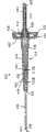
本发明的各种实施例表示在图1-7中。参照图1,这个实施例涉及一种针组件210,该针组件210具有壳体212,该壳体212具有流体进口端部214、流体出口端部216以及在各端部之间延伸的平截头体形外部壁218。外部壁218限定壳体内部220。壳体212还包括圆筒形内部壁224,该圆筒形内部壁224在壳体内部220中,从流体进口端部214大体与圆筒形外部壁218同心地延伸到通气塞900。圆筒形内部壁224和通气塞900限定闪流腔室226。Various embodiments of the invention are shown in Figures 1-7. Referring to FIG. 1, this embodiment relates to a
针组件210还包括流体进口套管236,该流体进口套管236具有外部端部和内部端部244,该外部端部限定尖锐斜面,该内部端部244固定地安装在壳体212的流体进口端部214中。流体进口套管236的特征还在于,大体圆筒形孔腔在各端部之间延伸,并且与壳体212的内部相连通。
针组件210还包括流体出口套管252。出口套管252包括钝头内部端部254、限定尖锐斜面的外部端部以及在各端部之间延伸的大体圆筒形孔腔。在各端部之间的出口套管252的部分牢固地固定在壳体212的出口端部216中。出口套管252安装成,内部端部254大体同轴地通到内部壁224中,并且出口套管252的内部端部254大体与进口套管236的内部端部244同轴地对准。另外,出口套管252的内部端部254与进口套管236的内部端部244仅间隔开一个小的距离。在出口套管252的内部端部254与进口套管236的内部端部244之间的小于0.5mm的轴向间隙可能导致不一致的闪流。
圆筒形内部壁224相对于出口套管252定尺寸,以实现血液穿过组件210的希望流动和实现有效闪流指示。具体地说,圆筒形内部壁224的尺寸优选地设定成,绕出口套管252提供约0.2mm的径向间隙,如在图1中由尺寸“c”指示的那样。这个间隙实现在闪流腔室226内的基本为层流的血液流动,并且防止血液溶血。另外,在圆筒形内部壁224与出口套管252之间的小的径向间隙能够使一滴血液薄薄地跨过径向间隙在闪流腔室226中扩展,以用非常小容积的血液提供放大的闪流指示。因而,在来自进口套管236的内部端部244的血液的最初出现时,迅速地实现容易看见的闪流指示。The cylindrical
针组件210还包括可密封套筒261,该可密封套筒261安装到壳体212的流体出口端部216上,并且当可密封套筒261在非偏压状态下时,覆盖出口套管252的外部端部258。然而,可密封套筒261可响应由抽空试管的塞子施加的压力而溃缩,用来将出口套管252的外部端部260推过可密封套筒261和抽空试管的塞子,如在现有技术中已知的那样。
以上实施例是以通气塞为例子加以描述的。然而,任何通气机构都是适合的。通气机构可以是例如由典型地疏水的母体或载体材料形成的多孔通气塞,该多孔通气塞涂有、浸渍有、或以其它方式包含亲水材料,该亲水材料在与水性的或含水的物质接触时膨胀。疏水载体材料也可以是但不限于,高密度聚乙烯、聚四氟乙烯、超高分子量聚乙烯、尼龙6、聚丙烯、聚偏氟乙烯以及聚醚砜。亲水材料的可膨胀性质由此在与血液接触时提供在通气元件中的密封功能。也可以使用一种多孔通气塞,该多孔通气塞使用生物现象在与血液接触时被密封,例如,通过堵塞通气元件的凝块和/或细胞凝集作用而被密封;通过在与水性流体接触时膨胀以密封通气元件的超级吸收材料;或单向阀(例如,诸如覆盖通气元件的塑料膜之类的薄折片、诸如橡胶或塑料鸭嘴阀之类的可变形密封、或在通气元件上的可变形包封件)。应该注意,这些各种机构的任意组合也是可能的。The above embodiments have been described taking the vent plug as an example. However, any venting mechanism is suitable. The vent mechanism may be, for example, a porous vent plug formed from a typically hydrophobic matrix or carrier material that is coated, impregnated with, or otherwise contains a hydrophilic material in combination with an aqueous or water-containing Substances expand on contact. Hydrophobic carrier materials can also be, but are not limited to, high density polyethylene, polytetrafluoroethylene, ultrahigh molecular weight polyethylene, nylon 6, polypropylene, polyvinylidene fluoride, and polyethersulfone. The expandable nature of the hydrophilic material thus provides a sealing function in the venting element when in contact with blood. A porous vent that seals upon contact with blood using biological phenomena, for example, by clots and/or cell agglutination that plug the vent element; by Superabsorbent material that swells to seal the vent; or a one-way valve (e.g., a thin flap such as a plastic film covering the vent, a deformable seal such as a rubber or plastic duckbill valve, or on the vent deformable envelope). It should be noted that any combination of these various mechanisms is also possible.
图2-4表示关于各种不同的通气塞的实施例。图2表示通气塞900a,该通气塞900a布置在圆筒形内部壁224a的端部处,并且配合到在壳体内部非病人壁300中的凹口301中。图3表示在与图2的位置相类似的位置中的通气塞,然而,通气塞900b具有肩部901b。图4表示通气塞900c,该通气塞900c布置在圆筒形内部壁224c和壳体内部非病人壁300中的凹口301二者中,并且具有肩部901c。在这些实施例的每一个中的通气塞位置都使得没有空气能够不通过通气机构(900a、b、c)而流出闪流腔室226并进入壳体内部220中。Figures 2-4 show embodiments relating to various vent plugs. FIG. 2 shows a vent plug 900a disposed at the end of the cylindrical inner wall 224a and fitted into a
图5和6提供在常规静脉穿刺之前和之后图1的针组件210的示意表示,其中,针组件210连接到保持器(未示出)上,并且刺穿病人的皮肤以实现静脉进入。在静脉进入时,血液进入静脉内套管236中,并且向闪流腔室226流动。血液从进口套管236流入在进口与出口套管之间的空间中,从而血液既流入出口套管252中,又流入闪流腔室226中。在这时,闪流腔室226指示成功的静脉进入,并且减小在图6中表示的壳体212中存在的空气的容积。在静脉进入之前在静脉内套管248的孔腔、闪流腔室226、壳体内部220以及非病人套管262的孔腔内处于大气压力的空气,由于静脉压力的影响因而经历压缩,并因此强迫该空气穿过在图6中表示的静脉内套管236进入闪流腔室226中,并且穿过通气塞进入腔室220中。由通气塞900防止血液流动进入壳体内部220中,该通气塞900允许加压空气流过它,但在与血液接触时实际上密封,有时完全密封,由此将压缩空气(在静脉压力下)拘限在壳体内部220中。一旦在腔室226内的压力和静脉压力相等,在整个针组件中的血液流动就停止。5 and 6 provide schematic representations of the
一旦在以上段落中叙述的步骤发生,并且静脉进入由静脉采血医师目视地确认,然后就将抽空容器(未示出)插入到保持器中,从而第二套管252的外部端部260穿透容器的塞子,如在现有技术中已知的那样。在塞子由第二套管252穿透时,负压梯度传递到腔室226,使血液从腔室226流到容器中。Once the steps recited in the preceding paragraphs have taken place, and venous entry is visually confirmed by the phlebotomist, an evacuated container (not shown) is then inserted into the holder so that the
以上描述的针组件为了方便使用优选地应该很小,但应该建造成保证可靠的和快速的闪流。在以上描述和示出的针组件中闪流的发生按照理想气体定律操作。具体地说,在非常低密度下,所有气体和蒸汽都接近理想气体状态,并且严密地遵循由下式给出的Boyle和Charles的定律:The needle assembly described above should preferably be small for ease of use, but should be constructed to ensure reliable and rapid flashover. The occurrence of flashover in the needle assembly described and illustrated above operates according to the ideal gas law. Specifically, at very low densities, all gases and vapors approach the ideal gas state and closely follow Boyle and Charles' law given by:
P1V1=P2V2P1 V1 =P2 V2
其中:in:
P1指示在针插入之前在针组件内的空气压力;P1 indicates the air pressure within the needle assembly prior to needle insertion;
P2指示在静脉进入之后在针组件内的空气压力;P2 indicates the air pressure within the needle assembly after venous entry;
V1指示在静脉进入之前在针组件内的空气容积;及V1 indicates the volume of air within the needle assembly prior to venous entry; and
V2指示在静脉进入之后在针组件内的空气容积。V2 indicates the volume of air within the needle assembly after venous access.
设计参数应该将针组件保持得尽可能小以便容易使用,同时保证由以上公式规定的适当容积。图5和6为了描绘理想气体定律的应用的目的,提供图1的针组件210的示意表示。在这方面,A表示穿过进口套管236的孔腔248的容积。B指示壳体内部220、闪流腔室226、穿过出口套管252的孔腔242以及可密封套筒261的总容积。再参考以上公式,P1是在使用之前在针组件210内的压力,并且因此大体上等于大气压力。大气压力将随时间和地点的不同而稍有变化。然而,为了这种分析的目的,将假定大气压力P1是760mm Hg。在以上公式中的P2是在静脉进入之后在针组件210中的静空间的容积。更具体地说,在静脉进入之后,血液将填充进口套管236的孔腔248,由此减小由在针组件210的剩余部分中由气体占据的容积,并因此增大在针组件210的剩余部分中的空气压力。具有近似如图1所示尺寸的针组件在静脉压力下将具有约790mm Hg的压力P2(采用止血带)。在以上公式中的V1限定在使用之前在针组件210中的总静空间的容积,并因此将等于A+B,如图5所示。V2限定在静脉进入之后在装置中的静空间,同时进口套管236的孔腔248填充有血液。因此,在以上公式中的V2将等于B。这些输入参数可用来定义用于针组件210的相应元件的最小所需尺寸,如在理想气体定律公式的如下应用中表示的那样。Design parameters should keep the needle assembly as small as possible for ease of use, while ensuring the proper volume dictated by the above formula. 5 and 6 provide a schematic representation of the
P1V1=P2V2P1 V1 =P2 V2
P1/P2=V2/V1P1 /P2 =V2 /V1
760/790=B/(A+B)760/790=B/(A+B)
0.962=B/(A+B)0.962=B/(A+B)
0.962(A+B)=B0.962(A+B)=B
0.038B=0.962A0.038B=0.962A
B=25.3AB=25.3A
因此,在壳体212、出口套管252及套筒261中的静空间有利地是由穿过进口套管236的孔腔248限定的容积的至少25.3倍,并且最有利地是孔腔248的容积的约26倍。然而,其它构造是可能的,并且将起作用,如本文描述的那样。Accordingly, the dead space in
当抽空试管放置成与出口套管252连通时的立即响应是,将血液从静脉抽吸到试管(未示出)中。最高压力梯度始终保持在静脉与抽空试管之间。轴向对准的进口套管236和出口套管252此时为从静脉进入抽空试管中的血液流动提供无障碍路径。The immediate response when the evacuated tube is placed in communication with
当所需的试管填充有血液时,将针组件从静脉移除。通气塞900的密封性质禁止在壳体内部220内的加压空气在这时运动到闪流腔室226中和进口套管236中,否则空气的这种运动会促进血液从静脉内套管末端滴落。When the desired tube is filled with blood, the needle assembly is removed from the vein. The sealing nature of
前述实施例表示结构分隔开的进口和出口套管,这些进口和出口套管彼此轴向对准,并且按彼此接近的、端部对端部的关系而设置。然而,以上描述的本发明的原理也可用单个套管实现,该单个套管在闪流腔室内形成有横向槽口或孔。例如,图7示意地表示具有壳体312的针组件310,该壳体312大体上与以上描述和示出的壳体212相同。针组件310与针组件210的不同之处在于,针组件310设有单个的双端部针套管336,并且该针套管336完全穿过壳体312。更具体地说,针套管336包括静脉进入端部338、非病人端部340以及在它们之间延伸的孔腔342。在内部壁324内的套管336的部分包括槽口或孔344,以提供在孔腔342与在内部壁324内的闪流腔室336之间的连通。针组件310按与以上描述和示出的针组件210基本上相同的方式起作用。The foregoing embodiments represent structurally spaced inlet and outlet bushings that are axially aligned with each other and disposed in proximate, end-to-end relationship to each other. However, the principles of the invention described above can also be implemented with a single sleeve having transverse slots or holes formed in the flash chamber. For example, FIG. 7 schematically shows a
图8-11描绘在本发明的又一个实施例中的针组件。在关于图1-7描述的针组件的一些实施例中,壳体内部包括通气塞900,该通气塞900将闪流腔室226/326与壳体内部220/320隔离。在这些先前描述的实施例中,通气塞被描述成当血液流动到闪流腔室时密封,由此禁止在壳体腔室220/320内可能积累的任何加压空气(如在初始闪流过程期间在空气从闪流腔室226/326排出到壳体腔室220/320中而产生的)沿着相反方向向着进口套管运动。在图8-11的实施例中,多孔通气元件在壳体内的定位位置使得通气元件将壳体划分成两个腔室,这两个腔室具有对其建立预定容积的大小和尺寸。此外,多孔通气元件对于血液保持多孔性,并且在与血液接触时不密封。优选地,血液在初始闪流指示时不接触多孔通气元件,但这样的接触在以后时刻发生在组件的使用期间,如本文将更详细描述的那样。8-11 depict a needle assembly in yet another embodiment of the invention. In some embodiments of the needle assemblies described with respect to Figures 1-7, the housing interior includes a
例如,图8-11表示与以上联系图1-6描述的针组件相类似的针组件410。如图8-11所示,针组件410包括壳体412,该壳体412具有流体进口端部或第一端部414和流体出口端部或第二端部416。针组件410包括限定壳体内部的外部壁418。外部壁418大致在第一端部414处沿纵向延伸,形成具有第一直径的细长纵向第一部分419。在第二端部416处,外部壁418形成第二部分421,该第二部分421具有的第二直径总体上大于第一部分419的第一直径。相应地,壳体412可以形成具有大致T形横截面的结构。在第二端部416处的外部壁418可以是分立元件428,该分立元件428可连接到形成壳体412的主体部分430,由此有助于针组件410的制造和组装。第一部分419和第二部分421可以相对于彼此按各种排列布置,只要它们能够起到用于在它们之间传输空气的作用,如本文说明的那样。For example, FIGS. 8-11 show a
针组件410还包括流体进口套管436,该流体进口套管436从壳体412的第一端部414延伸。流体进口套管436包括外部端部-该外部端部在病人穿刺末端438处限定诸如尖锐斜面之类的第一穿刺末端,并在壳体412的第一端部414内在敞开端部429处延伸,且可以固定地安装在其中。流体进口套管436的特征还在于,大体圆筒形孔腔在各端部之间延伸,并且与壳体412的内部相连通。
针组件410还包括第二穿刺末端,如从壳体412的第二端部416延伸的非病人穿刺末端462。如在图10中看到的那样,这可以通过在针组件410上设置一个呈流体出口套管452的形式的第二套管而实现。具体地说,流体出口套管452的端部可以限定形成非病人穿刺末端462的尖锐斜面。流体出口套管452在壳体412的第二端部416内延伸,并且可以固定地安装在其中。流体出口套管452的特征还在于,大体圆筒形孔腔与壳体412的内部相连通。出口套管452安装在壳体412内,从而内部端部464大体在其中同轴地通过,从而出口套管452大体与进口套管436的内部端部同轴地对准。优选地,这通过将出口套管452安装在与壳体412的第二端部416相邻的位置处而实现,从而出口套管452的内部端部464在壳体412内延伸到与进口套管436的内部端部439相邻的位置。如在图11B中看到的那样,出口套管452的内部端部464与进口套管436的内部端部439仅间隔开一个小的距离,由此在它们之间形成轴向间隙,该轴向间隙用于让血液流动到围绕着出口套管452的闪流腔室426中。形成轴向间隙的、在出口套管452的内部端部464与进口套管436的内部端部439之间的距离足以在静脉穿刺之后基于病人的血压保证血液流入闪流腔室426中。在一些实施例中,小于0.5mm的轴向间隙可导致不一致的闪流。
如在图11B中看到的那样,流体进口套管436和流体出口套管452在壳体412内定位和定尺寸,以便实现血液穿过组件410的希望流动和实现有效闪流指示。具体地说,壳体412的壁418的尺寸设定成,绕出口套管452在围绕其内部端部464的区域处提供约0.2mm的径向间隙。这个间隙实现在闪流腔室426内的基本为层流的血液流动,并且防止血液溶血。另外,在围绕内部端部464的区域处在壁418的内表面与出口套管452之间的小的径向间隙能够使一滴血液薄薄地跨过径向间隙在闪流腔室426中扩展,以用非常小容积的血液提供放大的闪流指示。因而,在闪流腔室426内的血液的最初出现时,迅速地实现容易看见的闪流指示。预期到的是,出口套管452的内部端部464可以部分地被支承在壳体412内,只要能够实现使血液绕内部端部464流入闪流腔室426中即可。As seen in FIG. 11B ,
在一种可选择布置中,提供单个套管,类似于联系图7说明的那个实施例。这样一种布置描绘在图12A和12B的实施例中(与血液采集组件一道表示,如本文将更详细描述的那样)。在这样一种布置中,流体进口套管和流体出口套管代表一个单一套管470,该套管470具有病人穿刺末端438、非病人穿刺末端462以及穿过它延伸的孔腔442,并且使套管470的本体固定地附加到壳体412的一部分上,并且完全通过壳体412。延伸过壳体412的套管470的一部分包括一个或多个开口,如槽口或孔444,以提供在孔腔442与在壳体412内的闪流腔室436之间的连通。在图12A和12B中看到的实施例中,两个分开的孔在套管470的相对两侧上示出,尽管预期到的是,可包括用以保证使血液流入闪流腔室436中的任意数量的这样的开口。In an alternative arrangement, a single sleeve is provided, similar to the embodiment described in connection with FIG. 7 . Such an arrangement is depicted in the embodiment of Figures 12A and 12B (shown together with a blood collection assembly, as will be described in more detail herein). In such an arrangement, the fluid inlet sleeve and the fluid outlet sleeve represent a
返回图8-11的实施例,针组件410还包括安装到壳体412的流体出口端部416上的可密封套筒461。这可以通过在壳体412的第二端部416处(如在元件428上)提供安装突起429而实现,可密封套筒461呈现的是一种可摩擦地配合或以其它方式附加在突起429上的弹性体元件。当可密封套筒461在非偏压状态下时,可密封套筒461覆盖在出口套管452的外部端部处的非病人穿刺末端462。然而,可密封套筒461可响应由抽空试管的塞子施加的压力而溃缩,用来将出口套管452的外部端部460推过可密封套筒461和抽空试管的塞子,如在现有技术中已知的那样。Returning to the embodiment of FIGS. 8-11 , the
图8-11的实施例还包括多孔通气元件910,该多孔通气元件910定位在壳体412的内部中。多孔通气元件910定位在壳体412内以将壳体412划分成两个不同的腔室,即由闪流腔室426代表的第一腔室和由副腔室427代表的第二腔室。多孔通气元件910可以由以上关于通气塞900描述的适当材料建造,虽然没有在接触时膨胀的亲水材料。按这种方式,多孔通气元件910适于穿过它而排出空气,并且呈现为一种包括多个微孔的多孔结构,这些微孔允许血液穿过微孔自身而通过,而在与血液接触时不堵塞穿过它的流体流动,如在现有技术中关于包括亲水材料的通气塞已知的那样。如本文更详细说明的那样,在针组件410的使用期间,在多孔通气元件910内的内部微孔由于在副腔室427内建立的负压,至少部分地用血液填充。与在副腔室427内的负压相结合的这样的被填充的微孔,防止在副腔室427与闪流腔室426之间的空气流动,并且保证穿过多孔通气元件910的血液流动的流体阻力,如将进一步详细描述的那样。The embodiment of FIGS. 8-11 also includes a
优选地,多孔通气元件910定位在壳体412的内部中的在第一部分419与第二部分421之间的位置。按这种方式,壳体412的第一部分419基本上限定闪流腔室426,并且壳体412的第二部分421基本上限定副腔室427。可选择地,多孔通气元件910可以定位在壳体412的内部中,在跨过在第一部分419的第一直径与第二部分421的第二直径之间的过渡区的位置处,如在图12A和12B的实施例中表示的那样。在任何情况下,多孔通气元件910都是大致圆筒形的部件,在其中具有轴向环绕着套管(具体是流体出口套管452)的一部分的中心开口。Preferably, the
壳体412的内部容积由闪流腔室426和副腔室427的容积以及由多孔通气元件910的微孔代表的容积的总和所限定。这样的内部容积构造成能够保证对于针组件410的一定属性,特别是在其使用期间当抽空试管施加到针组件410上时,关于副腔室427至少部分地抽空其中空气的一部分以在其中建立负压的能力。在副腔室427内的这样的负压,基于血液何时接触多孔通气元件910和部分地填充其微孔,穿过多孔通气元件910的微孔抽吸血液。在本发明的一个具体实施例中,壳体412的整个内部容积可以为约300mm3至约400mm3。这样一种容积对用于常规静脉穿刺的针组件410的预期使用特别有用,以便使用具有用于静脉穿刺的常规标尺的针套管从病人抽吸血液样品,如在现有技术中已知的那样。这样一种容积也能够使针组件对于具有比较低的血压的病人特别有用,因为壳体412的内部容积是足够的,以防止在初始静脉穿刺期间在内部容积空间中积累显著量的正压力。The internal volume of
多孔通气元件910优选地定位在壳体内部中以便将闪流腔室426限定成具有一个容积,该容积占壳体412的全部总容积的约百分之5至约百分之20,优选地占壳体412的全部总容积的约百分之7至约百分之12,该总容积包括副腔室427的容积和在多孔通气元件910内的微孔的容积。按这种方式,壳体412的剩余内部容积-由定位在多孔通气元件910与闪流腔室426之间的界面下游的内部容积限定,包括多孔通气元件910的内部微孔和副腔室427的容积,代表壳体412的内部容积的显著部分。闪流腔室426与壳体412的全部总容积的这样一种比值能够保证闪流腔室426具有足够的容积以适当地使初始闪流可见,优选地同时基于由强迫血液进入闪流腔室426中的静脉压力引起的在副腔室427内的初始压力积累来防止血液在初始静脉穿刺时完全地接触多孔通气元件910。这样的容积比值对于预期用途是有效的,如在本文中进一步详细描述的那样,其中在初始静脉穿刺时流入闪流腔室426中的血液并非完全地接触多孔通气元件910,并且优选地不接触多孔通气元件910,并且其中,空气的至少一部分基于抽空血液采集试管对于针组件410的施加而从副腔室427抽出。按这种方式,当病人穿刺末端438从病人移除和暴露于外部环境时,副腔室427可有效地从闪流腔室426内和从流体进口套管426内向着副腔室427抽吸血液,如抽入和抽过多孔通气元件910的微孔。在一个具体实施例中,壳体412的总内部容积是约380mm3,闪流腔室426具有约30mm3的容积,副腔室427具有约300mm3的容积,而多孔通气元件910的微孔呈现约50mm3的容积。
针组件410可以按如下方式组装。流体进口套管436穿过壳体412的第一端部414定位,从而敞开的内部端部439在第一部分419处定位在壳体412的内部部分中,并且病人穿刺末端438延伸到第一端部414的外部。流体出口套管452穿过相对端部定位在壳体412内,从而敞开的内部端部464在与流体进口套管436的内部端部439相邻的第一部分419处定位在壳体412的内部部分中,在它们之间留有些微间隙,并且非病人穿刺末端延伸到第二端部416的外部。流体进口套管436和流体出口套管452可以按任何已知方式附加在其中,优选地通过医学级粘合剂进行附加。
在仅包括单一套管470的一个可选择实施例中,这样的套管470附加在壳体412内,使得开口472在第一部分419处定位在壳体412的内部中,病人穿刺末端438延伸到第一端部414的外部,并且非病人穿刺末端462延伸到第二端部416的外部。In an alternative embodiment comprising only a
多孔通气元件910然后被插入在壳体412内,并且定位在流体出口套管454上(或在单一套管470上),并且此后将元件428附加到第二端部416上,以封闭壳体412的内部。然后将可密封套筒461附加在突起429上。这样,壳体412的内部与外部环境隔开,使得用于在壳体412的内部与外部环境之间的流体连通的唯一路径是通过病人穿刺末端438。The
这样组装的针组件410可与血液采集试管保持器800结合使用,如在图12中表示的实施例中描绘的那样。这样的组装件可以穿过血液采集试管保持器800后部敞开端部实现,从而整个针组件410插入到一部分,在该处至少病人穿刺末端438和进口套管436的至少一部分穿过血液采集试管保持器800的前端部延伸出。在针组件410的第二部分421沿径向大于第一部分419的实施例中,这样一种插入和布置使副腔室427能够完全包含在采集试管保持器800内的内部空间内,并且使闪流腔室426从其前端部延伸出。The
在使用中,针组件410可以设有连结到其上的采集试管保持器800。病人穿刺末端438穿过病人的皮肤插入并且插入到病人的血管系统中,优选地插入到静脉中。在静脉穿刺时,在壳体412内实现封闭环境,因为壳体412是一种完全封闭的结构,并且因为可密封套筒461封闭着壳体412的唯一出口(即,流体出口套管452)。病人的血压使血液流过病人穿刺末端438,流入流体进口套管436中,并流出内部端部439(或在图12的实施中流过开口472),流入围绕着出口套管452的内部端部464的闪流腔室426中。壳体412的透明或半透明性质使得在闪流腔室426内的血液是可见的,以提供静脉穿刺业已实现的指示。In use, the
由于壳体412的内部是封闭环境,所以进入闪流腔室426中的血液流动使空气被拘限在壳体内部中,包括在闪流腔室426、多孔通气元件910以及副腔室427内,以及在流体出口套管452内,使这样的被拘限的空气在其中被轻微地加压。闪流腔室426和副腔室427通过它们的大小和尺寸构造成使得其容积允许血液在这种初始静脉穿刺时流入闪流腔室426中,但在多孔通气元件910的微孔内和在副腔室427内空气压力的累积防止血液完全地接触多孔通气元件910,并且合意地防止在初始静脉穿刺时血液甚至部分地接触多孔通气元件910。Since the interior of
在这样的初始静脉穿刺和闪流可见之后,在其中具有负压的样品采集容器,如在现有技术中通常已知的抽空血液采集试管(未示出),被插入在试管保持器800内。这样的抽空容器的塞子(未示出)接触和移动可密封套筒461,使非病人穿刺末端462刺穿可密封套筒461并且刺穿抽空容器的塞子。在这时,在非病人穿刺末端462与抽空采集容器的内部之间建立流体连通。在抽空采集容器内的负压,将已经采集在闪流腔室426内的血液抽吸到流体出口套管452中,并且抽吸到抽空采集容器中。与在闪流腔室426内的血液一起,在抽空采集容器内的负压也将空气的至少一部分抽出闪流腔室426并通过多孔通气元件910的微孔抽出副腔室427,向着抽空采集容器抽吸并且抽吸到抽空采集容器中。另外,流体出口套管452和流体进口套管426的密切接近和对准,在空气从闪流腔室426和副腔室427被抽吸的同时,使血液从流体进口套管436和从病人处被抽吸。After such an initial venipuncture and visible flash, a sample collection container with negative pressure therein, such as an evacuated blood collection tube (not shown), as is generally known in the art, is inserted into the
这样的空气抽吸减小了在闪流腔室426和副腔室427内的压力,在其中相对于病人的血液流和相对于外部环境建立负压。在壳体412的内部中并且具体地说在闪流腔室426和副腔室427内已经建立的这种负压,从流体进口套管436内和从病人处将另外的血液抽吸到闪流腔室426中,使血液接触多孔通气元件910。关于填充闪流腔室426的这样的血液,血液完全地接触多孔通气元件910的表面-该表面在闪流腔室426内延伸,并且开始填充多孔通气元件910的微孔。直接在多孔通气元件910和闪流腔室426的界面处的多孔通气元件910的微孔的这样的填充,封锁了多孔通气元件以免于使空气流穿过它,但不是完全起密封的使用,因为血液不使多孔通气元件的材料膨胀或封锁空气流动,而是代之以仅仅物理地填充在多孔通气元件内的空隙。此外,由于在副腔室427内的空气的一部分已经从副腔室427抽出,所以副腔室427呈现为一个在其中相对于外部环境具有负压的封闭腔室。由于副腔室427的容积占了壳体412的整个内部容积的显著部分,所以在多孔通气元件910和闪流腔室426的界面处在被填充的微孔下游的壳体412的内部容积的显著部分,相对于内部容积的其余部分保持在负压下。因此,对于在多孔通气元件910的微孔内和在闪流腔室426内的血液而言,副腔室427将继续具有穿过多孔通气元件910的微孔向副腔室427抽吸的作用,而由于在闪流腔室426的界面处多孔通气元件910的微孔填充有血液,不会从副腔室427沿相反方向释放任何空气,由此,被填充的微孔有效地防止了穿过多孔通气元件910的空气流动。在副腔室427内由负压产生的抽吸,基于填充多孔通气元件910的微孔的血液和基于由多孔通气元件910的微孔产生的曲折路径,具有流体阻力,并因此是具有减弱的流体运动的逐渐抽吸。Such air suction reduces the pressure within the
在这时,抽空采集容器和副腔室427二者相对于外部环境(并且相对于病人的血液流)都处于负压之下,并因此都对从流体进口套管436的抽吸起作用。这种相互抽吸作用可以基本上在闪流腔室426内建立平衡,从而在闪流腔室426内包含的血液既不会穿过多孔通气元件910的微孔抽向或抽吸到副腔室427中,也不会穿过流体进口套管436抽吸到抽空采集容器中,而是在闪流腔室426内基本上保持在稳定状态下。抽空采集容器的负压,由于流体出口套管452和流体进口套管426的密切接近和对准,以及由于在闪流腔室426内建立的平衡(基于在抽空采集容器与抽空副腔室427之间的相对的抽吸力),通过流体进口套管436直接从病人抽吸血液。血液被连续地抽吸进入抽空采集容器中,使在采集容器内的压力逐渐增大。At this point, both the evacuated collection container and the
一旦抽空采集容器填充有所需数量的血液,就将容器从非病人穿刺末端462移除,由此解除在非病人穿刺末端462与抽空采集容器之间的流体连通,然后可密封套筒461覆盖并封锁非病人穿刺末端462。缺少来自抽空采集容器的负压的这种抽吸,在副腔室427内的负压实现穿过多孔通气元件910的微孔对于在闪流腔室426内的血液的轻微抽吸。然而,这样的抽吸,由于穿过多孔通气元件910的微孔的血液流动的曲折路径,是缓慢和逐渐的。Once the evacuated collection container is filled with the desired amount of blood, the container is removed from the non-patient piercing
如已说明的那样,此后,通过将第二抽空采集容器放置在保持器800内,并且通过刺穿塞子而在非病人穿刺末端462与该抽空采集容器的内部之间建立流体连通,可以将另外的抽空采集容器插入到试管保持器800中,并且用于穿过非病人穿刺末端462的样品采集,如以上描述的那样。在这种进一步取样时,抽空采集容器和副腔室427二者都在负压下,并因此都起作用以流体进口套管抽吸。如上述那样,这种作用基本上在闪流腔室426内建立平衡,由此防止在闪流腔室426内包含的血液向副腔室427抽吸或抽吸到其中(穿过多孔通气元件910)。由于流体出口套管452和流体进口套管426的密切接近和对准,抽空采集容器的负压穿过流体进口套管436直接从病人处抽吸血液,如上文中说明的那样。一旦任何这样的另外抽空采集容器填充有所需数量的血液,就将容器从非病人穿刺末端462移除,由此解除在非病人穿刺末端462与抽空采集容器之间的流体连通,然后可密封套筒461覆盖并封锁非病人穿刺末端462。As already explained, thereafter, by placing a second evacuated collection container within the
一旦所有的所需血液样品都已经按这种方式被抽吸,就从病人的血管系统(即从血液流)移除病人穿刺末端438,由此将病人穿刺末端438的开口暴露于外部环境。由于在壳体内部与外部环境之间的唯一连通路径是通过病人穿刺末端438,所以在副腔室427内相对于外部环境建立的负压将起到的作用是:使得在闪流腔室426内和在流体进口套管436内所包含的血液向着并穿过多孔通气元件910被逐渐地抽吸。这种抽吸作用将使得在流体进口套管436内所包含的任何血液远离病人穿刺末端438向着副腔室427移动和运动,由此防止了任何血液从病人穿刺末端438漏出流体进口套管436。在从病人体内移除病人穿刺末端438之后的较长时间段内,在副腔室427内的这种负压将继续具有穿过多孔通气元件910逐渐抽吸的作用,并且可以穿过多孔通气元件910抽吸在流体进口套管436和闪流腔室426内所包含的全部剩余血液,并且/或者将这些血液抽吸到副腔室427中。然后,可按已知方式适当地处置针组件410。Once all of the desired blood sample has been drawn in this manner,
图13A、13B以及13C描绘针组件的又一个实施例。在图13A-13C中表示的针组件类似于以上联系图8-11描述的实施例,虽然副腔室还包括多个内部区域,这些内部区域彼此流体连通,并且优选地气体通气地流体连通,以限定副腔室的内部容积。13A, 13B and 13C depict yet another embodiment of a needle assembly. The needle assembly shown in FIGS. 13A-13C is similar to the embodiment described above in connection with FIGS. 8-11 , although the subchamber also includes a plurality of interior regions that are in fluid communication with each other, and preferably in gaseous fluid communication, to define the internal volume of the secondary chamber.
具体地说,如在图13A中描绘的那样,针组件510包括壳体512,该壳体512具有流体进口端部或第一端部514和流体出口端部或第二端部516。针组件510还包括从壳体512的第一端部514延伸的流体进口套管536。流体进口套管536在外部端部与内部敞开端部529之间延伸,该外部端部限定第一穿刺末端,如在病人穿刺末端538处的尖锐斜面,该内部敞开端部529在壳体512的第一端部514内延伸,并且可以固定地安装其中。流体进口套管536的特征还在于,大体圆筒形孔腔在各端部之间延伸,并且与壳体512的内部相连通。Specifically, as depicted in FIG. 13A ,
针组件510还包括第二穿刺末端,如非病人穿刺末端,该第二穿刺末端从壳体512的第二端部516延伸,例如呈穿过流体出口套管552形式的第二套管。具体地说,流体出口套管552的端部可以限定形成非病人穿刺末端562的尖锐斜面。流体出口套管552在壳体512的第二端部516内延伸,并且可以固定地安装其中。流体出口套管552的特征还在于,大体圆筒形孔腔与壳体512的内部相连通。出口套管552安装在壳体512内,从而内部端部564大体同轴地在其中通过,从而出口套管552按联系在以上描述的图8-11中描绘的实施例所说明的类似方式,大体与进口套管536的内部端部轴向对准。例如,出口套管552的内部端部564可以与进口套管536的内部端部539仅间隔开一个小的距离,由此在它们之间形成用于使血液流入围绕着出口套管552的闪流腔室526中的轴向间隙,如在图13C中表示的那样,或者可以是单个套管,该单个套管在其中具有开口,如联系图12A-12B的实施例描述的那样。
如图13A-13C所示,针组件510在第一端部514处包括大致细长形的纵向部分,该细长纵向部分总体上包括内部壁515和外部壁517。内部壁515在壳体512内大致沿纵向延伸,具有限定呈闪流腔室526形式的内部腔室的第一直径。第二端部516限定第二部分,该第二部分具有的第二直径总体上大于内部壁515的第一直径。内部壁515的尺寸设定成,绕出口套管552在围绕其内部端部564的区域处提供约0.2mm的径向间隙,由此在闪流腔室526内实现基本为层流的血液流动,如以上说明的那样。出口套管552的内部端部564可以被支承在壳体512内,如在以上说明的实施例中那样。针组件510还可以包括可密封套筒561,该可密封套筒561安装到壳体512的流体出口端部516上,如通过安装突起529来安装,如以上说明的那样。As shown in FIGS. 13A-13C ,
如在图8-11的实施例中那样,针组件510还包括定位在壳体512的内部中的多孔通气元件910a。多孔通气元件910a是大致圆筒形的部件,在其中具有与套管(具体地流体出口套管452)的一部分轴向间隔开并且环绕该部分的中心开口。多孔通气元件910a可以由任何适当材料建造,如以上联系图8-11的实施例描述的那样。多孔通气元件910a定位在壳体512内的方式使得壳体512被划分成至少两个不同的腔室,即由闪流腔室526代表的第一腔室、和代表定位在多孔通气元件910a下游的壳体512的总内部容积的第二腔室。术语“下游”在这里用来表示相对于血液穿过针组件510的壳体512的预期流动的位置,所述预期流动也就是血液穿过壳体512从在流体进口套管536处的病人穿刺末端538、穿过敞开端部539、进入闪流腔室526、进入多孔通气元件910a以及向副腔室的流动。As in the embodiment of FIGS. 8-11 ,
多孔通气元件910a可以定位在壳体512的内部中,在跨过在第一端部514与第二端部516之间的过渡区的位置处。壳体512的内部容积由闪流腔室和副腔室的容积以及由多孔通气元件910a的微孔代表的容积之和限定。这样的内部容积构造成能够保证对于针组件510的一定属性,特别是当抽空试管施加到针组件510上时在其使用期间,关于副腔室至少部分地抽空其中空气的一部分以在其中建立负压的能力,如联系以上叙述的实施例描述的那样。在副腔室内的这样的负压,基于血液何时在多孔通气元件910a与闪流腔室526之间的界面处接触多孔通气元件910a和部分地填充其微孔,将血液抽吸到多孔通气元件910a的微孔中。
在图13A-13C的实施例中,副腔室包括多个不同的内部区域,如第一内部区域527a和第二内部区域527b。具体地说,在图8-11的实施例中,副腔室427代表在壳体412的第二端部416处的径向放大部分,该放大部分容纳适当尺寸的多孔通气元件910和对于副腔室427要求的适当内部容积,以按预期方式起作用(即,代表壳体512的总内部容积的大部分容积,以便在使用期间在其中能够建立负压,如以上描述的那样)。当与传统血液采集套具结合使用时,期望组件能够保持小的轮廓。这可以通过使副腔室具有减小的整体轮廓(具体地说具有减小的整体直径)而实现。In the embodiment of Figures 13A-13C, the secondary chamber includes a plurality of distinct interior regions, such as a first
为了对于预期用途保持副腔室的适当容积,副腔室可以沿壳体510纵向延伸。然而,重要的是,为了保证在副腔室与多孔通气元件910a的微孔之间存在足够的表面面积,以便副腔室在其预期用途中被抽空能够保证足够的抽吸作用。相应地,副腔室可以被划分成多个区域,如在图13A-13C的实施例中那样,其中,副腔室包括第一内部区域527a和第二内部区域527b,第一和第二内部区域527a、527b通过多孔通气元件910a彼此流体连通,并且也在闪流腔室526的下游相对于闪流腔室526流体连通。按这种方式,在闪流腔室下游的副腔室的总容积-该副腔室由多孔通气元件分隔出的多个内部区域组成,通过将副腔室保持为针壳体的总容积的显著量,足以实现本发明所描述的装置的预期使用。In order to maintain an appropriate volume for the intended use of the sub-chamber, the sub-chamber may extend longitudinally along the
尽管本实施例描绘两个内部区域527a和527b,但预期到,内部区域的数量可以是任何数量,只要副腔室的总内部容积(由定位在多孔通气元件910a下游的组合的内部区域的总容积代表),限定下游副腔室容积,该下游副腔室容积与以上关于图8-11的实施例描述的容积和比值相对应。Although this embodiment depicts two
副腔室的第一内部区域527a总体上可以布置成与壳体512的第二端部516相邻,而副腔室的第二内部区域527b总体上可以定位成同心地围绕着闪流腔室526的一部分。这可以通过将壳体512设置成两部分壳体而实现,第一端部514代表壳体的主体部分530,并且第二端部516代表壳体的分立体部分528,该分立体部分528能够连接到主体部分530,以形成壳体512。例如,壳体的主体部分530可以包括内部壁515和外部壁517,该内部壁515限定闪流腔室526,该外部壁517限定第二内部区域527b。主体部分520大致沿限定针组件510的轴线延伸,以限定细长纵向部分,内部壁515限定用于闪流腔室526的第一直径,并且外部壁517限定用于第二内部区域527b的第二直径。在壳体512的第二端部516处的分立体部分528的外部壁总体上限定第一内部区域527a,并且壳体512的主体部分530的外部壁517总体上限定第二内部区域527b。按这种方式,第二内部区域527b沿纵向从多孔通气元件910向远侧延伸,并且环形地围绕闪流腔室526的一部分。优选地,内部壁515和外部壁517都是透明的或半透明的,从而闪流腔室526的内容(如其中的血液流动)通过第二内部区域527b和/或通过第一内部区域527a是可见的。The first
壳体512的外部壁517一般可以从较大直径到较小直径向第一端部514锥缩。在图13B中的部分517p处所表示的外部壁517的一部分可以包括大体恒定的直径,用来在其中按紧密密封方式布置容纳多孔通气元件910a。可选择地,多孔通气元件910a可以包括沿锥缩外部壁517锥缩以与内部壁表面相重合的尺寸。The
图14-16描绘另一个实施例,在该实施例中,针组件510表示成与安全血液采集套具结合使用,该安全血液采集套具包括试管保持器810和枢转安全护套812,该试管保持器810用来在标准血液采集过程期间按已知方式容纳抽空血液采集试管(未示出),该枢转安全护套812用来在血液采集套具的使用之后保护针。14-16 depict another embodiment in which a
在使用中,针组件510按与以上联系图8-12描述的针组件410基本上相同的方式工作,第一和第二内部区域527a、527b按与在以前实施例中描述的副腔室427相同的方式起作用。具体地说,针组件510与试管保持器(如试管保持器810)相组合地提供。在流体进口套管536对于病人静脉穿刺时,血液基于病人的血压流入流体进口套管536中,并且流出其敞开端部539到闪流腔室526中,以便使血液流动可见,但并未完全地接触多孔通气元件910a的微孔。在观察到闪流之后,将抽空血液采集容器插入到试管保持器810中,以便由流体出口套管552的非病人穿刺末端562刺穿,该流体出口套管552将血液从闪流腔室526中抽出,并且将空气从第一和第二内部区域527a、527b中抽出,由此按以上描述的方式,减小在闪流腔室526和第一和第二内部区域527a、527b内的压力。此后,在闪流腔室526和第一和第二内部区域527a、527b内的负压通过流体进口套管536从病人抽吸血液,在多孔通气元件910a与闪流腔室526之间的界面处完全接触多孔通气元件910a的表面,以填充其微孔。由于在第一和第二内部区域527a、527b内的内部容积已经抽空,所以第一和第二内部区域527a、527b呈现为其中具有负压的封闭环境,并因此对于在多孔通气元件910a的被填充的微孔内和在闪流腔室526内的血液继续具有抽吸作用,如以上说明的那样。一旦全部试管被填充和移除,由于多孔通气元件910a的被填充的微孔相对于外部环境将第一和第二内部区域527a、527b密封,负压被保持在第一和第二内部区域527a、527b内,并且在第一和第二内部区域527a、527b内的这种负压继续影响对在多孔通气元件910a的微孔内和闪流腔室526内以及在流体进口套管536内所包含的血液的逐渐抽吸以使之远离病人穿刺末端538,由此防止任何血液从病人穿刺末端538泄漏。这样的继续抽吸可以使血液完全流过多孔通气元件910a的微孔,并且进入第一和第二内部区域527a、527b之一或两者中。In use, the
相对尺寸计算、容积及压力应用于本发明的示出的和未示出的实施例。相应地,由所附权利要求书所限定的范围不限于具体示出的实施例。本领域的技术人员可以在该范围中实现各种其它变更和修改而不脱离本发明的范围或精神,落在本发明范围中的所有的这样的变更和修改均应受到保护。Relative size calculations, volumes and pressures apply to both shown and non-shown embodiments of the invention. Accordingly, it is intended that the scope defined by the appended claims not be limited to the specific illustrated embodiments. Those skilled in the art can make various other changes and modifications within the scope without departing from the scope or spirit of the present invention, and all such changes and modifications falling within the scope of the present invention should be protected.
Claims (42)
Priority Applications (1)
| Application Number | Priority Date | Filing Date | Title |
|---|---|---|---|
| CN201510181907.7ACN104905801B (en) | 2008-03-07 | 2008-09-09 | Flashback blood collection needle |
Applications Claiming Priority (5)
| Application Number | Priority Date | Filing Date | Title |
|---|---|---|---|
| US12/044,354US7766879B2 (en) | 2008-03-07 | 2008-03-07 | Flashback blood collection needle |
| US12/044,354 | 2008-03-07 | ||
| US12/206,273US8795198B2 (en) | 2008-03-07 | 2008-09-08 | Flashback blood collection needle |
| US12/206,273 | 2008-09-08 | ||
| PCT/US2008/075716WO2009110922A1 (en) | 2008-03-07 | 2008-09-09 | Flashback blood collection needle |
Related Child Applications (2)
| Application Number | Title | Priority Date | Filing Date |
|---|---|---|---|
| CN201510181907.7ADivisionCN104905801B (en) | 2008-03-07 | 2008-09-09 | Flashback blood collection needle |
| CN201310294506.3ADivisionCN103356202B (en) | 2008-03-07 | 2008-09-09 | Flashback blood collection needle |
Publications (2)
| Publication Number | Publication Date |
|---|---|
| CN102014750Atrue CN102014750A (en) | 2011-04-13 |
| CN102014750B CN102014750B (en) | 2013-08-14 |
Family
ID=40029263
Family Applications (3)
| Application Number | Title | Priority Date | Filing Date |
|---|---|---|---|
| CN2008801287783AActiveCN102014750B (en) | 2008-03-07 | 2008-09-09 | flash flow blood collection needle |
| CN201510181907.7AActiveCN104905801B (en) | 2008-03-07 | 2008-09-09 | Flashback blood collection needle |
| CN201310294506.3AActiveCN103356202B (en) | 2008-03-07 | 2008-09-09 | Flashback blood collection needle |
Family Applications After (2)
| Application Number | Title | Priority Date | Filing Date |
|---|---|---|---|
| CN201510181907.7AActiveCN104905801B (en) | 2008-03-07 | 2008-09-09 | Flashback blood collection needle |
| CN201310294506.3AActiveCN103356202B (en) | 2008-03-07 | 2008-09-09 | Flashback blood collection needle |
Country Status (10)
| Country | Link |
|---|---|
| US (1) | US8795198B2 (en) |
| EP (2) | EP2285277B1 (en) |
| JP (3) | JP5502763B2 (en) |
| CN (3) | CN102014750B (en) |
| AU (1) | AU2008351992B2 (en) |
| BR (1) | BRPI0822380B8 (en) |
| CA (1) | CA2717855C (en) |
| ES (2) | ES2613584T3 (en) |
| MX (2) | MX345787B (en) |
| WO (1) | WO2009110922A1 (en) |
Families Citing this family (36)
| Publication number | Priority date | Publication date | Assignee | Title |
|---|---|---|---|---|
| RU2267800C1 (en)* | 2004-08-26 | 2006-01-10 | Государственное унитарное предприятие города Москвы-объединенный эколого-технологический и научно-исследовательский центр по обезвреживанию РАО и охране окружающей среды (ГУП МосНПО "Радон") | Alpha-emitting radionuclide identification method |
| EP3108812B1 (en) | 2007-03-07 | 2020-04-29 | Becton, Dickinson and Company | Safety blood collection assembly with indicator |
| US8888713B2 (en) | 2007-03-07 | 2014-11-18 | Becton, Dickinson And Company | Safety blood collection assembly with indicator |
| USD651308S1 (en) | 2008-03-07 | 2011-12-27 | Becton, Dickinson And Company | Safety blood collection assembly |
| US8795198B2 (en) | 2008-03-07 | 2014-08-05 | Becton, Dickinson And Company | Flashback blood collection needle |
| US7766879B2 (en) | 2008-03-07 | 2010-08-03 | Becton, Dickinson And Company | Flashback blood collection needle |
| US8603009B2 (en)* | 2008-03-07 | 2013-12-10 | Becton, Dickinson And Company | Flashback blood collection needle |
| US8323249B2 (en) | 2009-08-14 | 2012-12-04 | The Regents Of The University Of Michigan | Integrated vascular delivery system |
| PL2490592T3 (en)* | 2009-10-22 | 2014-11-28 | Medigard Ltd | Blood flash needle |
| WO2011146769A2 (en) | 2010-05-19 | 2011-11-24 | Tangent Medical Technologies Llc | Integrated vascular delivery system |
| US8814833B2 (en) | 2010-05-19 | 2014-08-26 | Tangent Medical Technologies Llc | Safety needle system operable with a medical device |
| AU2015203668B2 (en)* | 2011-02-01 | 2017-02-09 | Becton, Dickinson And Company | Flashback blood collection needle |
| US9022950B2 (en) | 2012-05-30 | 2015-05-05 | Magnolia Medical Technologies, Inc. | Fluid diversion mechanism for bodily-fluid sampling |
| US9060724B2 (en) | 2012-05-30 | 2015-06-23 | Magnolia Medical Technologies, Inc. | Fluid diversion mechanism for bodily-fluid sampling |
| US9204864B2 (en) | 2012-08-01 | 2015-12-08 | Magnolia Medical Technologies, Inc. | Fluid diversion mechanism for bodily-fluid sampling |
| EP2906269B1 (en)* | 2012-10-11 | 2018-01-03 | Magnolia Medical Technologies, Inc. | System for delivering a fluid to a patient with reduced contamination |
| CN109171766A (en) | 2012-11-30 | 2019-01-11 | 木兰医药技术股份有限公司 | Body fluid barrier means and the method for completely cutting off body fluid using body fluid barrier means |
| CA3183294A1 (en) | 2012-12-04 | 2014-06-12 | Magnolia Medical Technologies, Inc. | Sterile bodily-fluid collection device and methods |
| US10772548B2 (en) | 2012-12-04 | 2020-09-15 | Magnolia Medical Technologies, Inc. | Sterile bodily-fluid collection device and methods |
| CA2937744C (en) | 2014-02-04 | 2022-08-09 | Icu Medical, Inc. | Self-priming systems and methods |
| EP3721854B1 (en) | 2014-03-03 | 2023-04-05 | Magnolia Medical Technologies, Inc. | Apparatus and methods for disinfection of a specimen container |
| WO2016201406A1 (en) | 2015-06-12 | 2016-12-15 | Bullington Gregory J | Devices and methods for syringe-based fluid transfer for bodily-fluid sampling |
| EP4249119A3 (en) | 2015-09-03 | 2023-11-29 | Magnolia Medical Technologies, Inc. | System for maintaining sterility of a specimen container |
| USD806862S1 (en) | 2016-06-06 | 2018-01-02 | Medsource International Llc | Safety I.V. catheter |
| EP4218574A3 (en)* | 2016-11-18 | 2023-09-06 | Magnolia Medical Technologies, Inc. | Systems and methods for sample collection with reduced hemolysis |
| BR112020000944A2 (en)* | 2017-07-17 | 2020-07-14 | Becton, Dickinson And Company | device for trapping an initial blood flow |
| EP4555929A3 (en) | 2017-09-12 | 2025-06-25 | Magnolia Medical Technologies, Inc. | Fluid control device |
| JP7229267B2 (en) | 2017-12-07 | 2023-02-27 | マグノリア メディカル テクノロジーズ,インコーポレイテッド | Fluid control device and method of use |
| US10869993B2 (en)* | 2018-04-05 | 2020-12-22 | Becton, Dickinson And Company | Introducer needle with notches for improved flashback |
| BR112021004090A2 (en)* | 2018-09-06 | 2021-05-25 | Becton, Dickinson And Company | arterial blood gas collection system |
| WO2020163744A1 (en) | 2019-02-08 | 2020-08-13 | Magnolia Medical Technologies, Inc. | Devices and methods for bodily fluid collection and distribution |
| CN113784793B (en) | 2019-03-11 | 2023-09-19 | 木兰医药技术股份有限公司 | Fluid control device and method of using the same |
| CA3169051A1 (en) | 2019-09-10 | 2021-03-18 | Medsource International Llc | An intravenous catheter device |
| JP7664926B2 (en) | 2019-12-11 | 2025-04-18 | マグノリア メディカル テクノロジーズ,インコーポレイテッド | Fluid transfer device with integrated flow-based assay and method of using same - Patents.com |
| US12337123B2 (en) | 2021-05-06 | 2025-06-24 | Medsource Labs, Llc | Safety intravenous cannula |
| US12186497B2 (en) | 2022-01-14 | 2025-01-07 | Medsource International Llc | Intravenous cannula |
Citations (4)
| Publication number | Priority date | Publication date | Assignee | Title |
|---|---|---|---|---|
| US4207870A (en)* | 1978-06-15 | 1980-06-17 | Becton, Dickinson And Company | Blood sampling assembly having porous vent means vein entry indicator |
| US4305406A (en)* | 1980-06-13 | 1981-12-15 | Becton, Dickinson And Company | Needle assemblies with anti-backflow features |
| US20030229315A1 (en)* | 2002-06-11 | 2003-12-11 | Bd Medical Products, Pte. Ltd. | Flashback blood collection needle with needle shield |
| WO2006022716A1 (en)* | 2004-08-16 | 2006-03-02 | Becton, Dickinson And Company | Flashback blood collection needle |
Family Cites Families (160)
| Publication number | Priority date | Publication date | Assignee | Title |
|---|---|---|---|---|
| US6003A (en)* | 1849-01-09 | Method of bending shelf from which iron tubes abe made | ||
| US4106497A (en) | 1977-02-04 | 1978-08-15 | Becton, Dickinson And Company | Multiple sample needle assembly with indicator means |
| US4340068A (en)* | 1980-06-18 | 1982-07-20 | Becton, Dickinson And Company | Multiple sample needle with vein entry indicator |
| US4312362A (en)* | 1980-10-02 | 1982-01-26 | Becton, Dickinson And Company | Single sample needle with vein entry indicator |
| AU7969682A (en) | 1981-03-16 | 1982-09-23 | Becton Dickinson & Company | I.v. needle with vein entry indicator |
| US4572210A (en) | 1981-07-01 | 1986-02-25 | Marquest Medical Products, Inc. | Syringe with means for allowing passage of air while preventing the passage of blood to obtain a gas-free blood sample |
| US4573976A (en) | 1984-05-24 | 1986-03-04 | Dolores A. Smith | Shielded needle |
| US4641663A (en) | 1985-05-17 | 1987-02-10 | Juhn Steven K | Apparatus for collecting specimens |
| US4795443A (en) | 1987-04-16 | 1989-01-03 | Peachtree Medical, Inc. | Syringe sealing device and method |
| US4900307A (en) | 1987-04-29 | 1990-02-13 | Kulli John C | Safety retracting needle for use with syringe |
| US4813426A (en) | 1987-11-09 | 1989-03-21 | Habley Medical Technology Corporation | Shielded safety syringe having a retractable needle |
| US4887998A (en) | 1987-12-14 | 1989-12-19 | Martin Catherine L | Hypodermic needle guard |
| US4840619A (en) | 1988-05-26 | 1989-06-20 | Hughes Elaine L | Syringe |
| US5015241A (en) | 1988-06-20 | 1991-05-14 | Feimer Michael P | Safety system for hypodermic syringe and needle |
| US4894055A (en) | 1988-12-28 | 1990-01-16 | Sudnak Paul J | Needle guard assembly for use with hypodermic syringes and the like |
| US4994046A (en) | 1988-12-30 | 1991-02-19 | Vann T. Wesson | Needle guard for syringe |
| US4923447A (en) | 1989-02-17 | 1990-05-08 | Morgan Michael W | Syringe assembly |
| US5256153A (en) | 1989-03-02 | 1993-10-26 | Hake Lawrence W | Hypodermic needle guard and method to prevent needle stick injuries |
| US5120311A (en) | 1989-11-01 | 1992-06-09 | Medical Safety Products, Inc. | Blood collection tube holder |
| US5356392A (en) | 1990-05-09 | 1994-10-18 | Safety Syringes, Inc. | Shielded blood collection tube holder |
| US5195985A (en) | 1990-05-25 | 1993-03-23 | Hall John E | Syringe having a retractable needle |
| US5070885A (en) | 1990-06-11 | 1991-12-10 | Care Medical Devices, Inc. | Disposable blood collection device |
| US5222502A (en) | 1990-09-26 | 1993-06-29 | Terumo Kabushiki Kaisha | Blood collecting needle |
| US5215534A (en) | 1991-12-02 | 1993-06-01 | Lawrence De Harde | Safety syringe system |
| US5242417A (en) | 1992-01-13 | 1993-09-07 | Paudler Gary M | Self closing hinged syringe guard |
| US5318547A (en) | 1992-01-15 | 1994-06-07 | Altschuler Bruce R | Sheathed hypodermic needle |
| US5246428A (en) | 1992-07-30 | 1993-09-21 | Falknor Donald W | Needle safety mechanism |
| US5295975A (en) | 1992-10-28 | 1994-03-22 | Lockwood Jr Hanford N | Hypodermic needle safety device with sliding outer cover |
| US5295970A (en)* | 1993-02-05 | 1994-03-22 | Becton, Dickinson And Company | Apparatus and method for vascular guide wire insertion with blood flashback containment features |
| US5921964A (en) | 1993-02-08 | 1999-07-13 | Martin; Robin | Safety blood collecting device |
| US5984899A (en) | 1993-02-11 | 1999-11-16 | Beech Medical Products, Inc. | Needle protector device having a lockable protective cover which is unlockable during actuation |
| US5795336A (en) | 1993-02-11 | 1998-08-18 | Beech Medical Products, Inc. | Automatic needle protector having features for facilitating assembly |
| US5389085A (en) | 1993-02-11 | 1995-02-14 | International Medical Consultants, Inc. | Automatic needle protector |
| US5336199A (en) | 1993-11-12 | 1994-08-09 | Castillo Leo S | Medical needle and needle sheath assembly |
| US5348544A (en) | 1993-11-24 | 1994-09-20 | Becton, Dickinson And Company | Single-handedly actuatable safety shield for needles |
| EP0698372B1 (en) | 1994-08-18 | 2002-05-02 | Becton, Dickinson and Company | Pre-assembled safety needle holder |
| US5439449A (en) | 1994-04-22 | 1995-08-08 | E-Z-Em, Inc. | Flow visualization needle system |
| US5466223A (en) | 1994-06-20 | 1995-11-14 | Becton, Dickinson And Company | Needle assembly having single-handedly activatable needle barrier |
| US5411492A (en) | 1994-07-05 | 1995-05-02 | Sturman; Martin | Hypodermic needle protector |
| CA2157999C (en) | 1994-09-23 | 1999-08-03 | Robert B. Odell | Manually pivoted barrier assembly for a piercing element |
| US5501675A (en) | 1994-12-27 | 1996-03-26 | Becton, Dickinson And Company | Safety catheter assembly having safety stop push button |
| US5595566A (en) | 1995-01-31 | 1997-01-21 | Unique Management Enterprises, Inc. | Apparatus for shielding a syringe needle |
| US5599313A (en) | 1995-02-03 | 1997-02-04 | Becton, Dickinson And Company | Needle shield assembly having safety indication features |
| CA2168615A1 (en) | 1995-03-07 | 1996-09-08 | Timothy J. Erskine | Catheter-advancement actuated needle retraction system |
| WO1996029107A1 (en) | 1995-03-17 | 1996-09-26 | Radiometer Medical A/S | Shielding means |
| US5702369A (en) | 1995-06-06 | 1997-12-30 | Mercereau; Steven Frank | Extendable device for enclosing cutting surfaces of surgical instruments |
| US5549558A (en) | 1995-06-09 | 1996-08-27 | Martin; Robin P. | Self sheathing safety needle |
| US5687740A (en) | 1995-06-29 | 1997-11-18 | Becton, Dickinson And Company | Needle holder assembly including sleeve of thermoplastic elastomer |
| US5542932A (en) | 1995-07-20 | 1996-08-06 | Daugherty; Charles W. | Bloodless flashback vent |
| EP0763369B1 (en) | 1995-09-18 | 2002-01-09 | Becton, Dickinson and Company | Needle shield with collapsible cover |
| JP3398531B2 (en) | 1995-10-03 | 2003-04-21 | セイコーインスツルメンツ株式会社 | Recording paper take-up mechanism |
| ATE481124T1 (en) | 1996-02-27 | 2010-10-15 | Braun Melsungen Ag | NEEDLE TIP PROTECTION FOR SUBCUTANEOUS INJECTIONS |
| US6629959B2 (en) | 1996-02-27 | 2003-10-07 | Injectimed, Inc. | Needle tip guard for percutaneous entry needles |
| US5879337A (en) | 1997-02-27 | 1999-03-09 | Injectimed, Inc. | Needle tip guard for hypodermic needles |
| US5688241A (en) | 1996-04-15 | 1997-11-18 | Asbaghi; Hooman Ali | Automatic non-reusable needle guard |
| US5704920A (en) | 1996-05-17 | 1998-01-06 | Becton, Dickinson And Company | Manually driven needle shield assembly |
| US5893845A (en) | 1996-06-21 | 1999-04-13 | Becton Dickinson & Company | Telescoping needle shield |
| US5665075A (en) | 1996-07-03 | 1997-09-09 | Becton, Dickinson And Company | Method of making a needle shield assembly |
| US5672161A (en) | 1996-09-20 | 1997-09-30 | Becton, Dickinson And Company | Needle assembly having single-handedly activated needle barrier |
| US5733265A (en) | 1996-09-25 | 1998-03-31 | Becton Dickinson And Company | Shielded needle assembly |
| US5738665A (en) | 1996-09-26 | 1998-04-14 | Becton, Dickinson And Company | Shield and actuator for needles |
| US6159184A (en) | 1997-03-10 | 2000-12-12 | Safety Syringes, Inc. | Disposable self-shielding unit dose syringe guard |
| US6648856B1 (en) | 1997-05-27 | 2003-11-18 | Jorge Luis Argento | Needle for medical and/or veterinary use that includes an extensible telescopic system that covers the needle avoiding its future use |
| FR2767469B1 (en) | 1997-08-25 | 2000-06-16 | Raphael Mosseri | PROTECTION DEVICE FOR A CUTTING AND / OR PERFORATING TOOL |
| EP1030597B1 (en) | 1997-11-12 | 2007-02-28 | MDC Investment Holdings, Inc. | Fluid collection device with captured rectractable needle |
| IT1304761B1 (en) | 1998-01-20 | 2001-03-29 | Nardino Righi | DISPOSABLE SAFETY SYRINGE. |
| FR2774294B1 (en) | 1998-02-04 | 2000-04-14 | Marc Brunel | DEVICE FOR AUTOMATICALLY INJECTING A DOSE OF MEDICINAL PRODUCT |
| US5957892A (en) | 1998-03-12 | 1999-09-28 | Specialized Health Products, Inc. | Safety catheter insertion apparatus and methods |
| US6749588B1 (en) | 1998-04-09 | 2004-06-15 | Becton Dickinson And Company | Catheter and introducer needle assembly with needle shield |
| US7223258B2 (en) | 1998-08-28 | 2007-05-29 | Becton Dickinson And Company | Safety shield assembly |
| US6436086B1 (en) | 1998-08-28 | 2002-08-20 | Becton Dickinson And Company | Method of using a safety shield assembly and related combinations thereof |
| US6298541B1 (en) | 1998-08-28 | 2001-10-09 | Becton, Dickinson And Company | Method for making a safety shield assembly and related combinations thereof |
| USD442280S1 (en) | 1998-08-28 | 2001-05-15 | Becton Dickinson And Company | Needle shield |
| US6440104B1 (en) | 1998-08-28 | 2002-08-27 | Becton, Dickinson And Company | Safety shield assembly |
| FR2782627B1 (en) | 1998-09-01 | 2001-02-09 | Vygon | ARTERIAL PUNCTURE NEEDLE |
| WO2000023130A1 (en) | 1998-10-16 | 2000-04-27 | Bio-Plexus, Inc. | Releasable locking needle assembly with optional release accessory therefor |
| US6149629A (en) | 1999-05-14 | 2000-11-21 | Specialized Health Products, Inc. | Medical needle safety apparatus and methods |
| US6648855B2 (en) | 1999-08-23 | 2003-11-18 | Becton, Dickinson And Company | Safety needle assembly |
| US6699217B2 (en) | 1999-08-23 | 2004-03-02 | Becton, Dickinson And Company | Safety needle assembly |
| US6780169B2 (en) | 1999-08-23 | 2004-08-24 | Becton, Dickinson And Company | Safety shield assembly |
| US6837877B2 (en) | 1999-08-23 | 2005-01-04 | Becton, Dickinson And Company | Safety shield assembly |
| US6254575B1 (en) | 1999-11-04 | 2001-07-03 | Specialized Health Products | Reaccessible medical needle safety devices and methods |
| US7198618B2 (en) | 1999-11-04 | 2007-04-03 | Tyco Healthcare Group Lp | Safety shield for medical needles |
| US6592556B1 (en) | 2000-07-19 | 2003-07-15 | Tyco Healthcare Group Lp | Medical needle safety apparatus and methods |
| US8226617B2 (en) | 1999-11-04 | 2012-07-24 | Tyco Healthcare Group Lp | Safety shield apparatus and mounting structure for use with medical needle devices |
| PT1607115E (en) | 1999-11-18 | 2009-11-30 | Tyco Healthcare | Safety needle autosheath |
| US6171284B1 (en) | 2000-03-15 | 2001-01-09 | Wang-Hsiang Kao | Syringe needle cover structure |
| DE60104466T2 (en) | 2000-04-04 | 2005-08-04 | Nipro Corp. | Indwelling needle assembly |
| US6471677B2 (en) | 2000-04-06 | 2002-10-29 | Gem Plastics, Inc. | Fluid collection device with protective shield |
| US6972002B2 (en) | 2000-04-28 | 2005-12-06 | Specialized Health Products, Inc. | Passively activated safety shield for a catheter insertion needle |
| US6533760B2 (en) | 2000-05-02 | 2003-03-18 | Becton, Dickinson And Company | Flashback blood collection needle |
| US6613022B1 (en) | 2000-05-05 | 2003-09-02 | Safety Syringes, Inc. | Passive needle guard for syringes |
| US6391004B1 (en) | 2000-07-21 | 2002-05-21 | Retrax Safety Systems, Inc. | Fluid collector assembly |
| DE10044383C2 (en) | 2000-09-08 | 2003-02-06 | Disetronic Licensing Ag | Needle protector |
| JP4013239B2 (en) | 2000-10-23 | 2007-11-28 | ニプロ株式会社 | Indwelling needle assembly |
| US6524277B1 (en) | 2000-12-29 | 2003-02-25 | Ethicon, Inc. | Method and apparatus for an intravascular device showing flashback |
| US6659983B2 (en) | 2001-01-05 | 2003-12-09 | Becton Dickinson And Company | Needle assembly |
| US6773419B2 (en) | 2001-01-05 | 2004-08-10 | Jamieson William Maclean Crawford | Blood collection set |
| US6485469B1 (en) | 2001-01-10 | 2002-11-26 | Sherwood Services Ag | Shielded dental safety needle |
| US6811545B2 (en) | 2001-01-31 | 2004-11-02 | Vincent L. Vaillancourt | Safety needle |
| US6595931B2 (en) | 2001-02-05 | 2003-07-22 | Sherwood Services Ag | Fluid collection holder |
| WO2002070056A1 (en) | 2001-03-02 | 2002-09-12 | Sherwood Services Ag | Passive safety shield |
| US6554807B2 (en) | 2001-04-12 | 2003-04-29 | Peter Gollobin | Protective sheath for winged needles |
| US6712792B2 (en)* | 2001-05-02 | 2004-03-30 | Becton, Dickinson And Company | Flashback blood collection needle |
| AU3708902A (en) | 2001-05-04 | 2002-11-07 | Becton Dickinson & Company | Passively activated safely needle |
| AU2002354638B2 (en) | 2001-07-09 | 2009-01-22 | Becton, Dickinson And Company | Needle shield assembly having hinged needle shield and flexible cannula lock |
| US6716199B2 (en) | 2001-07-18 | 2004-04-06 | Deharde Lawrence G. | Safety syringe system |
| US6860872B2 (en) | 2001-08-20 | 2005-03-01 | Joseph Von Teichert | Safety syringe/catheter |
| US20030050608A1 (en) | 2001-09-12 | 2003-03-13 | Robert Brown | Passive fluid collection device |
| US20030055385A1 (en) | 2001-09-18 | 2003-03-20 | Paul Schooler | Displaceable syringe guard |
| US6695819B2 (en) | 2001-10-19 | 2004-02-24 | Terumo Medical Corporation | Safety needle assembly |
| US6805689B2 (en) | 2001-10-23 | 2004-10-19 | Wei Chen | Safety blood collector device |
| US6984223B2 (en) | 2001-11-13 | 2006-01-10 | Becton, Dickinson And Company | Needle safety device |
| EP1555037B1 (en) | 2001-11-13 | 2012-02-29 | Becton, Dickinson and Company | Shieldable needle assembly |
| US8066678B2 (en) | 2001-12-17 | 2011-11-29 | Bard Access Systems, Inc. | Safety needle with collapsible sheath |
| US6974423B2 (en) | 2002-03-11 | 2005-12-13 | Becton, Dickinson And Company | Needle assembly |
| US6623461B1 (en) | 2002-03-15 | 2003-09-23 | Becton, Dickinson And Company | Forward shielding safety device |
| FR2837107B1 (en) | 2002-03-18 | 2005-02-25 | Sedat | NEEDLE PROTECTION DEVICE FOR SYRINGE, AND INJECTION DEVICE COMPRISING SYRINGE AND PROTECTIVE DEVICE |
| US6918891B2 (en) | 2002-03-21 | 2005-07-19 | Becton Dickinson Co | Safety device |
| US6976976B2 (en) | 2002-03-27 | 2005-12-20 | Safety Syringes, Inc. | Syringe with needle guard injection device |
| CA2419232A1 (en) | 2002-04-04 | 2003-10-04 | Becton, Dickinson And Company | Medical device |
| US7001363B2 (en) | 2002-04-05 | 2006-02-21 | F. Mark Ferguson | Safety shield for medical needles |
| US6835190B2 (en) | 2002-04-17 | 2004-12-28 | Smiths Medical Asd, Inc. | Retractable safety infusion needle |
| US6761704B2 (en) | 2002-05-02 | 2004-07-13 | Becton, Dickinson And Company | Safety blood collection needle assembly |
| EP1362608B1 (en) | 2002-05-15 | 2006-02-01 | Becton Dickinson and Company | Shieldable needle device |
| US6997913B2 (en) | 2002-06-07 | 2006-02-14 | Becton, Dickinson And Company | Needle safety device |
| US7083600B2 (en) | 2002-08-08 | 2006-08-01 | Advanced Medical Sharps, Inc. | Safety needle and shield |
| US6869415B2 (en) | 2002-11-05 | 2005-03-22 | Vacumate, Llc | Safety device for blood collection |
| US8231583B2 (en) | 2002-12-04 | 2012-07-31 | Becton, Dickinson And Company | Safety needle assembly with passive pivoting shield |
| CN100364481C (en) | 2002-12-16 | 2008-01-30 | 贝克顿·迪金森公司 | Safety needle assembly |
| US6846302B2 (en) | 2002-12-31 | 2005-01-25 | Teva Medical Ltd. | Needle protector device |
| EP1605992B1 (en) | 2003-01-30 | 2018-11-21 | Becton, Dickinson and Company | Holder with safety shield for a drug delivery device |
| US7524308B2 (en) | 2003-04-16 | 2009-04-28 | Becton, Dickinson And Company | Safety shielding needle assembly with passive shielding |
| US7037292B2 (en) | 2003-06-27 | 2006-05-02 | Sherwood Services Ag | Safety needle shield apparatus |
| US8251961B2 (en) | 2003-09-22 | 2012-08-28 | Smiths Medical Asd, Inc. | Safety needle assembly and method for making the same |
| JP2005176928A (en) | 2003-12-16 | 2005-07-07 | Bd Medical Products Pte Ltd | Flashback blood collection needle having needle shield |
| EP1703929B1 (en) | 2003-12-18 | 2009-10-21 | Tecpharma Licensing AG | Releasable injection device |
| US6958054B2 (en) | 2004-01-28 | 2005-10-25 | P. Rowan Smith | Intravenous catheter device |
| US7211065B2 (en) | 2004-02-19 | 2007-05-01 | Miller Stuart H | Enveloping needle stick protection device |
| US8226576B2 (en) | 2004-02-25 | 2012-07-24 | Becton, Dickinson And Company | Safety blood collection holder |
| US20050228345A1 (en) | 2004-04-12 | 2005-10-13 | Chang-Ming Yang | Single-use safety injector structure |
| US20080086085A1 (en) | 2004-05-03 | 2008-04-10 | Leroy Brown | Blood drawing device with flash detection |
| US7530967B2 (en) | 2004-05-03 | 2009-05-12 | Clearview Patient Safety Technologies, Llc | Porous multiple sample sleeve and blood drawing device for flash detection |
| US7226432B2 (en) | 2004-05-03 | 2007-06-05 | Clear View Patient Safety Products, Llc | Blood drawing device |
| US7396343B2 (en) | 2004-05-03 | 2008-07-08 | Clear View Patient Safty Products, Llc | Blood drawing device with flash detection |
| EP1602328A1 (en) | 2004-06-02 | 2005-12-07 | Becton, Dickinson and Company | Flashback Blood Collection Needle |
| US7294119B2 (en) | 2004-06-10 | 2007-11-13 | Safety Syringes, Inc. | Passive delivery system diluents mixing and delivery |
| US7201740B2 (en) | 2004-07-01 | 2007-04-10 | Becton, Dickinson And Company | Forward-shielding blood collection set |
| US8500690B2 (en) | 2004-07-01 | 2013-08-06 | Becton, Dickinson And Company | Passively shielding needle device |
| FR2874505B1 (en) | 2004-08-27 | 2007-06-08 | Sedat Sa | INJECTION DEVICE COMPRISING A SYRINGE |
| US20060129064A1 (en) | 2004-11-29 | 2006-06-15 | Becton, Dickinson And Company | Blood collection set with an expanded internal volume |
| US7648480B2 (en) | 2005-03-31 | 2010-01-19 | Terumo Medical Corporation | Safety needle assembly |
| GB0517699D0 (en) | 2005-09-01 | 2005-10-05 | Owen Mumford Ltd | Needle shroud assembly |
| US20070100296A1 (en) | 2005-10-31 | 2007-05-03 | Becton, Dickinson And Company | Single-handedly actuatable shield for needles |
| JP5007793B2 (en) | 2006-09-21 | 2012-08-22 | ニプロ株式会社 | Indwelling needle |
| US7727190B2 (en) | 2007-01-04 | 2010-06-01 | Miller Stuart H | Enveloping needle stick protection device |
| DE102007009340A1 (en) | 2007-02-27 | 2008-08-28 | Tecpharma Licensing Ag | Needle protection device for injection unit, has needle support, which has needle protective sleeve and integrated needle support removal device for removing needle support of injection unit |
| US8795198B2 (en) | 2008-03-07 | 2014-08-05 | Becton, Dickinson And Company | Flashback blood collection needle |
| US7766879B2 (en) | 2008-03-07 | 2010-08-03 | Becton, Dickinson And Company | Flashback blood collection needle |
| US8439870B2 (en) | 2008-09-10 | 2013-05-14 | B. Braun Medical Inc. | Safety needle assembly and methods |
- 2008
- 2008-09-08USUS12/206,273patent/US8795198B2/enactiveActive
- 2008-09-09JPJP2010549628Apatent/JP5502763B2/enactiveActive
- 2008-09-09EPEP08873192.2Apatent/EP2285277B1/enactiveActive
- 2008-09-09BRBRPI0822380Apatent/BRPI0822380B8/enactiveIP Right Grant
- 2008-09-09ESES08873192.2Tpatent/ES2613584T3/enactiveActive
- 2008-09-09MXMX2014007721Apatent/MX345787B/enunknown
- 2008-09-09CACA2717855Apatent/CA2717855C/enactiveActive
- 2008-09-09CNCN2008801287783Apatent/CN102014750B/enactiveActive
- 2008-09-09EPEP16187765.9Apatent/EP3138494B1/enactiveActive
- 2008-09-09CNCN201510181907.7Apatent/CN104905801B/enactiveActive
- 2008-09-09WOPCT/US2008/075716patent/WO2009110922A1/enactiveApplication Filing
- 2008-09-09MXMX2010009785Apatent/MX2010009785A/enactiveIP Right Grant
- 2008-09-09AUAU2008351992Apatent/AU2008351992B2/enactiveActive
- 2008-09-09ESES16187765Tpatent/ES2754375T3/enactiveActive
- 2008-09-09CNCN201310294506.3Apatent/CN103356202B/enactiveActive
- 2013
- 2013-11-21JPJP2013241295Apatent/JP2014061426A/ennot_activeWithdrawn
- 2013-11-21JPJP2013241296Apatent/JP5665949B2/enactiveActive
Patent Citations (4)
| Publication number | Priority date | Publication date | Assignee | Title |
|---|---|---|---|---|
| US4207870A (en)* | 1978-06-15 | 1980-06-17 | Becton, Dickinson And Company | Blood sampling assembly having porous vent means vein entry indicator |
| US4305406A (en)* | 1980-06-13 | 1981-12-15 | Becton, Dickinson And Company | Needle assemblies with anti-backflow features |
| US20030229315A1 (en)* | 2002-06-11 | 2003-12-11 | Bd Medical Products, Pte. Ltd. | Flashback blood collection needle with needle shield |
| WO2006022716A1 (en)* | 2004-08-16 | 2006-03-02 | Becton, Dickinson And Company | Flashback blood collection needle |
Also Published As
| Publication number | Publication date |
|---|---|
| AU2008351992B2 (en) | 2013-01-10 |
| CN103356202B (en) | 2015-05-20 |
| EP2285277A1 (en) | 2011-02-23 |
| US20090227896A1 (en) | 2009-09-10 |
| ES2754375T3 (en) | 2020-04-17 |
| CN103356202A (en) | 2013-10-23 |
| EP3138494A1 (en) | 2017-03-08 |
| JP2011528237A (en) | 2011-11-17 |
| EP3138494B1 (en) | 2019-08-07 |
| BRPI0822380B8 (en) | 2021-06-22 |
| JP5502763B2 (en) | 2014-05-28 |
| CN102014750B (en) | 2013-08-14 |
| JP2014061426A (en) | 2014-04-10 |
| CA2717855C (en) | 2016-11-15 |
| US8795198B2 (en) | 2014-08-05 |
| CA2717855A1 (en) | 2009-09-11 |
| MX345787B (en) | 2017-02-15 |
| AU2008351992A1 (en) | 2009-09-11 |
| CN104905801A (en) | 2015-09-16 |
| CN104905801B (en) | 2018-02-06 |
| BRPI0822380B1 (en) | 2020-01-21 |
| ES2613584T3 (en) | 2017-05-24 |
| JP2014030773A (en) | 2014-02-20 |
| WO2009110922A1 (en) | 2009-09-11 |
| BRPI0822380A2 (en) | 2017-05-09 |
| MX2010009785A (en) | 2010-09-28 |
| JP5665949B2 (en) | 2015-02-04 |
| EP2285277B1 (en) | 2016-11-02 |
Similar Documents
| Publication | Publication Date | Title |
|---|---|---|
| CN102014750A (en) | flash flow blood collection needle | |
| CN103402429B (en) | flash flow blood collection needle | |
| CN102014749A (en) | flash flow blood collection needle | |
| US8282605B2 (en) | Flashback blood collection needle | |
| JP5620541B2 (en) | Actuating method of needle assembly | |
| AU2012211447B2 (en) | Flashback blood collection needle | |
| AU2013202972B2 (en) | Flashback blood collection needle | |
| JP5905932B2 (en) | Needle assembly | |
| AU2014202181B2 (en) | Flashback blood collection needle |
Legal Events
| Date | Code | Title | Description |
|---|---|---|---|
| C06 | Publication | ||
| PB01 | Publication | ||
| C10 | Entry into substantive examination | ||
| SE01 | Entry into force of request for substantive examination | ||
| C14 | Grant of patent or utility model | ||
| GR01 | Patent grant |