CN102013848A - Solar power generation device provided with parabolic cylindrical surface for gathering light and plane for lighting - Google Patents
Solar power generation device provided with parabolic cylindrical surface for gathering light and plane for lightingDownload PDFInfo
- Publication number
- CN102013848A CN102013848ACN2010105240060ACN201010524006ACN102013848ACN 102013848 ACN102013848 ACN 102013848ACN 2010105240060 ACN2010105240060 ACN 2010105240060ACN 201010524006 ACN201010524006 ACN 201010524006ACN 102013848 ACN102013848 ACN 102013848A
- Authority
- CN
- China
- Prior art keywords
- receiving mechanism
- plane
- solar
- luminous energy
- gathering receiving
- Prior art date
- Legal status (The legal status is an assumption and is not a legal conclusion. Google has not performed a legal analysis and makes no representation as to the accuracy of the status listed.)
- Pending
Links
- 238000010248power generationMethods0.000titleabstractdescription3
- 230000007246mechanismEffects0.000claimsdescription48
- 238000006243chemical reactionMethods0.000claimsdescription5
- 230000005622photoelectricityEffects0.000claims1
- 238000011084recoveryMethods0.000claims1
- 238000010586diagramMethods0.000description5
- 230000000694effectsEffects0.000description3
- 238000005516engineering processMethods0.000description3
- 230000009286beneficial effectEffects0.000description1
- 230000007812deficiencyEffects0.000description1
- 238000003912environmental pollutionMethods0.000description1
- 239000011159matrix materialSubstances0.000description1
- 238000000034methodMethods0.000description1
- XLYOFNOQVPJJNP-UHFFFAOYSA-NwaterSubstancesOXLYOFNOQVPJJNP-UHFFFAOYSA-N0.000description1
Images


Classifications
- Y—GENERAL TAGGING OF NEW TECHNOLOGICAL DEVELOPMENTS; GENERAL TAGGING OF CROSS-SECTIONAL TECHNOLOGIES SPANNING OVER SEVERAL SECTIONS OF THE IPC; TECHNICAL SUBJECTS COVERED BY FORMER USPC CROSS-REFERENCE ART COLLECTIONS [XRACs] AND DIGESTS
- Y02—TECHNOLOGIES OR APPLICATIONS FOR MITIGATION OR ADAPTATION AGAINST CLIMATE CHANGE
- Y02E—REDUCTION OF GREENHOUSE GAS [GHG] EMISSIONS, RELATED TO ENERGY GENERATION, TRANSMISSION OR DISTRIBUTION
- Y02E10/00—Energy generation through renewable energy sources
- Y02E10/50—Photovoltaic [PV] energy
Landscapes
- Photovoltaic Devices (AREA)
Abstract
Description
Translated fromChinese所属技术领域:Technical field:
本发明涉及一种太阳能应用技术,特别是一种利用抛物柱面聚光原理接收太阳能的抛物柱面聚光平面采光太阳能发电装置,该装置通过反光面的反光聚焦作用接收太阳能,可大幅提高太阳能的接收效率。The invention relates to a solar energy application technology, in particular to a parabolic cylindrical surface concentrating planar lighting solar power generation device which utilizes the principle of parabolic cylindrical surface concentrating to receive solar energy. receiving efficiency.
背景技术:Background technique:
太阳能是一种清洁能源,取之不尽、用之不竭,也不会造成环境污染,如今,无论在沿海城市,还是在内陆城市,太阳能产品正越来越多地进入人们的视野,太阳能路灯、太阳能草坪灯、太阳能庭院灯、太阳能楼道灯、公交站台灯、交通信号灯等等,各种太阳能热水器也已经走近千家万户。但这些太阳能产品大多数都没有聚光功能,造成太阳能利用率低下。太阳能接收元件表面的光强提高一倍,太阳能接收元件的接收效率将提高一倍,目前太阳能产业技术竞争的焦点主要是太阳能接收效率之争,可见提高接收效率对整个行业重要程度,因此能否有效的提高太阳能接收元件的光照强度,就成为人们利用太阳能时最为关注的问题。Solar energy is a kind of clean energy, inexhaustible and inexhaustible, and will not cause environmental pollution. Nowadays, whether in coastal cities or inland cities, solar energy products are increasingly entering people's field of vision. Solar street lights, solar lawn lights, solar garden lights, solar corridor lights, bus station lights, traffic lights, etc., all kinds of solar water heaters have also approached thousands of households. But most of these solar products do not have light concentrating function, resulting in low utilization rate of solar energy. If the light intensity on the surface of the solar receiving element is doubled, the receiving efficiency of the solar receiving element will be doubled. At present, the focus of technological competition in the solar industry is mainly the competition for solar receiving efficiency. It can be seen that improving the receiving efficiency is important to the entire industry. Therefore, whether Effectively improving the light intensity of solar receiving elements has become the most concerned issue when people utilize solar energy.
近些年,国外在一些太阳能电站的光伏矩阵中实现了太阳能聚光接收,国内也有类似的试验装置,但这些装置结构复杂、体积庞大、造价高难以在太阳能家用产品上得到推广。In recent years, foreign countries have achieved concentrated solar energy reception in the photovoltaic matrix of some solar power plants, and there are similar test devices in China, but these devices are complex in structure, bulky and expensive, and it is difficult to promote them in solar household products.
发明内容:Invention content:
为了克服现有的聚光装置机械结构复杂、体积庞大、造价高等缺点.本发明针对现有技术存在的不足,对现有技术进行了改进,提出了一种体积小、结构简单可靠、成本低的太阳能聚光接收装置、它可实现太阳能的聚光接收。In order to overcome the shortcomings of the existing concentrating device, such as complex mechanical structure, bulky volume, and high cost, the present invention aims at the deficiencies of the existing technology, improves the existing technology, and proposes a small volume, simple and reliable structure, and low cost The solar concentrated light receiving device, which can realize the concentrated light reception of solar energy.
本发明解决其技术问题所采用的技术方案是:在一个长方形箱体内安装了多个太阳能聚光接收机构,各太阳能聚光接收机构都由一块抛物柱面反光镜和一个光能接收器构成,各太阳能聚光接收机构整齐排列在长方形箱体内,在长方形箱体的上面盖有一块平面透明盖板,平面透明盖板将各太阳能聚光接收机构封闭在长方形箱体内,各太阳能聚光接收机构的抛物柱面反光镜的开口正对平面透明盖板,各个太阳能聚光接收机构的抛物柱面反光镜的焦线相互平行,各个太阳能聚光接收机构的抛物柱面反光镜的焦线位于同一个与平面透明盖板平行的平面上,各个太阳能聚光接收机构的光能接收器安装在该太阳能聚光接收机构的抛物柱面反光镜的焦线上,The technical solution adopted by the present invention to solve its technical problems is: a plurality of solar energy concentrating receiving mechanisms are installed in a rectangular box, and each solar concentrating receiving mechanism is made of a parabolic reflector and a light energy receiver. The solar concentrating receiving mechanisms are neatly arranged in a rectangular box, and a flat transparent cover is covered on the rectangular box. The flat transparent cover seals each solar concentrating receiving mechanism in the rectangular box, and each solar concentrating receiving mechanism The opening of the parabolic reflector is facing the plane transparent cover, the focal lines of the parabolic reflectors of each solar concentrating receiving mechanism are parallel to each other, and the focal lines of the parabolic reflectors of each solar concentrating receiving mechanism are located at the same On a plane parallel to the plane transparent cover plate, the light energy receivers of each solar concentrating receiving mechanism are installed on the focal line of the parabolic reflector of the solar concentrating receiving mechanism,
本发明的实施例一:各太阳能聚光接收机构的光能接收器都由一块长直的平面太阳能电池板构成,
各太阳能聚光接收机构光能接收器的平面太阳能电池板与该太阳能聚光接收机构的抛物柱面反光镜的对称面相互垂直,各太阳能聚光接收机构光能接收器的平面太阳能电池板对称的位于该太阳能聚光接收机构的抛物柱面反光镜的对称面的两侧,各太阳能聚光接收机构光能接收器的平面太阳能电池板位于该太阳能聚光接收机构抛物柱面反光镜的反射面和焦线之间,The planar solar panels of the light energy receivers of each solar concentrating receiving mechanism are perpendicular to the symmetry planes of the parabolic reflectors of the solar concentrating receiving mechanism, and the planar solar panels of the light energy receivers of each solar concentrating receiving mechanism are symmetrical. On both sides of the symmetry plane of the parabolic reflector of the solar concentrating receiving mechanism, the planar solar panels of the light energy receivers of each solar concentrating receiving mechanism are located on the reflection of the parabolic reflective mirror of the solar concentrating receiving mechanism between the surface and the focal line,
当太阳光垂直于平面透明盖板入射时,入射光线通过各太阳能聚光接收机构的抛物柱面反光镜的反射聚焦后都能照射在各光能接收器的平面太阳能电池板上,照射在各光能接收器的平面太阳能电池板上的光能通过各光能接收器的平面太阳能电池板转换为电能,通过各太阳能聚光接收机构的抛物柱面反光镜的反光聚焦作用大幅提高了照射在各光能接收器的平面太阳能电池板上的太阳光的强度,因而大幅提高了各光能接收器的光电转换率。When sunlight is incident perpendicular to the plane transparent cover plate, the incident light can be irradiated on the plane solar panels of each light energy receiver after being reflected and focused by the parabolic reflectors of each solar concentrating receiving mechanism, and irradiated on each The light energy on the planar solar panel of the light energy receiver is converted into electrical energy through the planar solar panel of each light energy receiver, and the reflective focusing effect of the parabolic reflector of each solar concentrating receiving mechanism greatly improves the irradiation in the The intensity of sunlight on the planar solar panel of each light energy receiver greatly improves the photoelectric conversion rate of each light energy receiver.
本发明的实施例二:为了减小长方形箱体的厚度,各太阳能聚光接收机构光能接收器的平面太阳能电池板位于该太阳能聚光接收机构的抛物柱面反光镜的焦线和平面透明盖板之间。Embodiment 2 of the present invention: In order to reduce the thickness of the rectangular box, the plane solar panels of the light energy receivers of each solar concentrating receiving mechanism are positioned at the focal line and the plane of the parabolic reflector of the solar concentrating receiving mechanism. between the covers.
本发明的有益效果是:通过各抛物柱面反光镜的反光聚焦作用大幅提高了照射在光能接收器上的太阳光的强度,因而大幅提高了光能接收器的光电转换率,实现了在强光和弱光的环境下都有较高的光电转换率。The beneficial effects of the present invention are: the intensity of sunlight irradiated on the light energy receiver is greatly improved through the reflective focusing effect of each parabolic reflector, thereby greatly improving the photoelectric conversion rate of the light energy receiver, and realizing It has a high photoelectric conversion rate under both strong light and low light environments.
附图说明:Description of drawings:
下面结合附图和实施例对本发明进一步说明。The present invention will be further described below in conjunction with the accompanying drawings and embodiments.
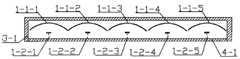
图1是本发明的整体结构图。Fig. 1 is the overall structure diagram of the present invention.
图2是本发明实施例一的整体结构图的A-A剖视图。Fig. 2 is an A-A sectional view of the overall structure diagram of
图3是本发明实施例一的太阳能聚光接收机构剖视图的放大图。Fig. 3 is an enlarged view of the sectional view of the solar concentrating receiving mechanism according to the first embodiment of the present invention.
图4是本发明实施例二的整体结构图的A-A剖视图。Fig. 4 is an A-A sectional view of the overall structure diagram of Embodiment 2 of the present invention.
图5是本发明实施例二的太阳能聚光接收机构剖视图的放大图。Fig. 5 is an enlarged view of the sectional view of the solar concentrating receiving mechanism according to the second embodiment of the present invention.
图6是抛物柱面的示意图。Fig. 6 is a schematic diagram of a parabolic cylinder.
在图6的抛物柱面构成图中:抛物线L,准线L1,顶点O,焦点f,对称轴L2,抛物柱面S,准平面S1,对称面S2,焦线L3。In the composition diagram of the parabolic cylinder in Fig. 6: parabola L, directrix L1, vertex O, focal point f, symmetry axis L2, parabolic cylinder S, quasi-plane S1, symmetry plane S2, focal line L3.
具体实施方式:Detailed ways:
在图1和图2中,在长方形箱体3-1内安装了由抛物柱面反光镜1-1-1和光能接收器1-2-1构成的太阳能聚光接收机构一、由抛物柱面反光镜1-1-2和光能接收器1-2-2构成的太阳能聚光接收机构二、由抛物柱面反光镜1-1-3和光能接收器1-2-3构成的太阳能聚光接收机构三、由抛物柱面反光镜1-1-4和光能接收器1-2-4构成的太阳能聚光接收机构四、由抛物柱面反光镜1-1-5和光能接收器1-2-5构成的太阳能聚光接收机构五,五个太阳能聚光接收机构的整齐排列在长方形箱体3-1内,五个太阳能聚光接收机构的结构和各项尺寸相同,五个太阳能聚光接收机构的光能接收器的结构和各项尺寸相同,在长方形箱体3-1的上面盖有一块平面透明盖板4-1,平面透明盖板4-1将五个太阳能聚光接收机构的封闭在长方形箱体3-1内,In Fig. 1 and Fig. 2, the solar concentrating receiving mechanism that is made of parabolic reflector 1-1-1 and light energy receiver 1-2-1 is installed in rectangular box 3-1. The solar concentrating receiving mechanism two that surface reflector 1-1-2 and light energy receiver 1-2-2 constitute, the solar concentrating mechanism that is made of parabolic reflector 1-1-3 and light energy receiver 1-2-3 Light receiving mechanism three, the solar energy concentrating receiving mechanism that is formed by parabolic reflector 1-1-4 and light energy receiver 1-2-4 Four, by parabolic reflector 1-1-5 and
五个太阳能聚光接收机构的抛物柱面反光镜的开口正对平面透明盖板,五个太阳能聚光接收机构的抛物柱面反光镜的焦线相互平行,五个太阳能聚光接收机构的抛物柱面反光镜的焦线位于同一个与平面透明盖板平行的平面上,各个太阳能聚光接收机构的光能接收器安装在该太阳能聚光接收机构的抛物柱面反光镜的焦线上,The openings of the parabolic reflectors of the five solar concentrating receiving mechanisms face the plane transparent cover, the focal lines of the parabolic reflectors of the five solar concentrating receiving mechanisms are parallel to each other, and the parabolic reflectors of the five solar concentrating receiving mechanisms The focal line of the cylindrical reflector is located on the same plane parallel to the plane transparent cover, and the light energy receivers of each solar concentrating receiving mechanism are installed on the focal line of the parabolic reflector of the solar concentrating receiving mechanism,
本发明的实施例一:图3中给出了第一太阳能聚光接收机构的结构,在图3中第一太阳能聚光接收机构由抛物柱面反光镜1-1-1和光能接收器1-2-1构成,光能接收器1-2-1由平面太阳能电池板10-5构成,Embodiment one of the present invention: the structure of the first solar energy concentrating receiving mechanism is provided in Fig. 3, and in Fig. 3 the first solar concentrating receiving mechanism is made up of parabolic reflector 1-1-1 and light energy receiver 1 -2-1 composition, the light energy receiver 1-2-1 is composed of a planar solar panel 10-5,
平面太阳能电池板10-5与抛物柱面反光镜1-1-1的对称面相互垂直,平面太阳能电池板10-5对称的位于抛物柱面反光镜1-1-1的对称面的两侧,平面太阳能电池板10-5位于抛物柱面反光镜1-1-1的反射面和焦线之间,The plane of symmetry of the planar solar cell panel 10-5 and the parabolic reflector 1-1-1 is perpendicular to each other, and the planar solar cell panel 10-5 is symmetrically located on both sides of the symmetry plane of the parabolic reflector 1-1-1 , the planar solar panel 10-5 is located between the reflective surface of the parabolic reflector 1-1-1 and the focal line,
当太阳光垂直于平面透明盖板4-1入射时,入射光线通过抛物柱面反光镜1-1-1的反射聚焦后都能垂直照射在平面太阳能电池板10-5上,照射在平面太阳能电池板10-5上的光能通过平面太阳能电池板10-5转换为电能,通过抛物柱面反光镜1-1-1的反光聚焦作用大幅提高了照射在平面太阳能电池板10-5上的太阳光的强度,因而大幅提高了光能接收器1-2-1的光电转换率。When sunlight is incident perpendicular to the plane transparent cover plate 4-1, the incident light can be vertically irradiated on the plane solar cell panel 10-5 after being reflected and focused by the parabolic reflector 1-1-1, and irradiated on the plane solar panel 10-5. The light energy on the battery panel 10-5 is converted into electrical energy through the planar solar panel 10-5, and the reflective focusing effect of the parabolic reflector 1-1-1 greatly improves the light energy irradiated on the planar solar panel 10-5. The intensity of sunlight thus greatly increases the photoelectric conversion rate of the light energy receiver 1-2-1.
本发明的实施例二:在图4和图5中,为了减少长方形箱体3-1厚度,平面太阳能电池板10-4位于抛物柱面反光镜1-1-1的焦线和平面透明盖板4-1之间。Embodiment 2 of the present invention: in Fig. 4 and Fig. 5, in order to reduce the thickness of the rectangular box 3-1, the planar solar cell panel 10-4 is positioned at the focal line of the parabolic reflector 1-1-1 and the planar transparent cover between plates 4-1.
Claims (1)
Priority Applications (1)
| Application Number | Priority Date | Filing Date | Title |
|---|---|---|---|
| CN2010105240060ACN102013848A (en) | 2010-10-25 | 2010-10-25 | Solar power generation device provided with parabolic cylindrical surface for gathering light and plane for lighting |
Applications Claiming Priority (1)
| Application Number | Priority Date | Filing Date | Title |
|---|---|---|---|
| CN2010105240060ACN102013848A (en) | 2010-10-25 | 2010-10-25 | Solar power generation device provided with parabolic cylindrical surface for gathering light and plane for lighting |
Publications (1)
| Publication Number | Publication Date |
|---|---|
| CN102013848Atrue CN102013848A (en) | 2011-04-13 |
Family
ID=43843900
Family Applications (1)
| Application Number | Title | Priority Date | Filing Date |
|---|---|---|---|
| CN2010105240060APendingCN102013848A (en) | 2010-10-25 | 2010-10-25 | Solar power generation device provided with parabolic cylindrical surface for gathering light and plane for lighting |
Country Status (1)
| Country | Link |
|---|---|
| CN (1) | CN102013848A (en) |
Citations (7)
| Publication number | Priority date | Publication date | Assignee | Title |
|---|---|---|---|---|
| US4024852A (en)* | 1976-02-05 | 1977-05-24 | Esperance Paul M L | Solar energy reflector-collector |
| CN1160441A (en)* | 1994-10-05 | 1997-09-24 | 泉久雄 | Wavelength separating and light condensing type generating and heating apparatus |
| CN1773190A (en)* | 2004-11-12 | 2006-05-17 | 中国科学院电工研究所 | A solar heat and power cogeneration system |
| CN101017859A (en)* | 2007-03-05 | 2007-08-15 | 云南师范大学 | Slot light collection solar thermal power united supply compound system |
| WO2009002281A2 (en)* | 2007-06-26 | 2008-12-31 | Goldensun Slovakia, S.R.O. | Parabolic concentrating photovoltaic converter |
| CN101748390A (en)* | 2008-12-18 | 2010-06-23 | 北京北方微电子基地设备工艺研究中心有限责任公司 | Heating device and semiconductor processing device |
| CN101795100A (en)* | 2010-03-24 | 2010-08-04 | 武汉大学 | Solar photovoltaic generation system |
- 2010
- 2010-10-25CNCN2010105240060Apatent/CN102013848A/enactivePending
Patent Citations (7)
| Publication number | Priority date | Publication date | Assignee | Title |
|---|---|---|---|---|
| US4024852A (en)* | 1976-02-05 | 1977-05-24 | Esperance Paul M L | Solar energy reflector-collector |
| CN1160441A (en)* | 1994-10-05 | 1997-09-24 | 泉久雄 | Wavelength separating and light condensing type generating and heating apparatus |
| CN1773190A (en)* | 2004-11-12 | 2006-05-17 | 中国科学院电工研究所 | A solar heat and power cogeneration system |
| CN101017859A (en)* | 2007-03-05 | 2007-08-15 | 云南师范大学 | Slot light collection solar thermal power united supply compound system |
| WO2009002281A2 (en)* | 2007-06-26 | 2008-12-31 | Goldensun Slovakia, S.R.O. | Parabolic concentrating photovoltaic converter |
| CN101748390A (en)* | 2008-12-18 | 2010-06-23 | 北京北方微电子基地设备工艺研究中心有限责任公司 | Heating device and semiconductor processing device |
| CN101795100A (en)* | 2010-03-24 | 2010-08-04 | 武汉大学 | Solar photovoltaic generation system |
Similar Documents
| Publication | Publication Date | Title |
|---|---|---|
| CN201846274U (en) | Parabolic cylinder lighting solar generating device | |
| CN201846278U (en) | Solar generating set through parabolic cylinder spotlight and half-cylinder lighting | |
| CN201846271U (en) | Parabolic cylinder condensation concave closed cavity lighting solar generating set | |
| CN201846279U (en) | Solar power generation device using parabolic cylinder surface for light focusing and plane surface for light collecting | |
| CN201846270U (en) | Solar electrical energy generation device utilizing reflecting and focusing of parallel rays through double parabolic cylinder | |
| CN201854215U (en) | Hemispherical daylighting and concentrating multiplication solar power generation device | |
| CN201846275U (en) | Solar power generation device capable of lighting through secondary reflection parabolic cylinder light gathering plane | |
| CN201846277U (en) | Parabolic cylinder focusing semi-cylindrical surface closed cavity lighting solar generating device | |
| CN201878047U (en) | Solar power generation device capable of lighting through parabolic cylindrical surface and condensation cylindrical surface | |
| CN202135080U (en) | Parabolic cylindrical surface concentrating cylindrical surface closed cavity daylighting solar power generation device | |
| CN101976980A (en) | Solar power generation device using parabolic light-gathering cylindrical surface for light-collecting | |
| CN201846272U (en) | Solar power generating device capable of lighting through secondary reflection plane | |
| CN202076958U (en) | Secondary reflection hemispherical lighting solar power generation device | |
| CN201846262U (en) | Secondary reflection paraboloid of revolution light collecting solar electrical energy generation device | |
| CN202135078U (en) | Parabolic Cylindrical Concentrating Parabolic Cylindrical Closed Cavity Daylighting Solar Power Generation Device | |
| CN101964614B (en) | Parabolic cylinder light-gathering parabolic cylinder closed cavity daylighting solar generating set | |
| CN102013848A (en) | Solar power generation device provided with parabolic cylindrical surface for gathering light and plane for lighting | |
| CN101951203B (en) | Twice-reflected hemispherical-light collecting solar generating device | |
| CN201846269U (en) | Solar power generation device capable of lighting through secondary reflection light gathering plane | |
| CN101964612B (en) | Secondary reflection spherical closed cavity light-collecting solar generating device | |
| CN202135079U (en) | Secondary reflection parabolic cylindrical surface concentrating semi-cylindrical surface daylighting solar power generation device | |
| CN101976974A (en) | Solar energy generation device multiplying concentration and adopting spherical surface for lighting | |
| CN101976983A (en) | Secondary reflection solar power generating device with parabolic cylinder for collecting light and triangular closed cavity for daylighting | |
| CN201846276U (en) | Lighting solar generating device with parabolic-cylinder closing cavity capable of condensing light on secondary reflection parabolic cylinder | |
| CN201994876U (en) | Secondary reflection closed cavity body lighting solar generating device with parabolic cylinder surface and light focusing cylindrical surface |
Legal Events
| Date | Code | Title | Description |
|---|---|---|---|
| C06 | Publication | ||
| PB01 | Publication | ||
| C10 | Entry into substantive examination | ||
| SE01 | Entry into force of request for substantive examination | ||
| C02 | Deemed withdrawal of patent application after publication (patent law 2001) | ||
| WD01 | Invention patent application deemed withdrawn after publication | Open date:20110413 |