CN102012061B - Electric warmer - Google Patents
Electric warmerDownload PDFInfo
- Publication number
- CN102012061B CN102012061BCN2009101901752ACN200910190175ACN102012061BCN 102012061 BCN102012061 BCN 102012061BCN 2009101901752 ACN2009101901752 ACN 2009101901752ACN 200910190175 ACN200910190175 ACN 200910190175ACN 102012061 BCN102012061 BCN 102012061B
- Authority
- CN
- China
- Prior art keywords
- heating element
- space heater
- heater
- carbon nanotube
- electric heater
- Prior art date
- Legal status (The legal status is an assumption and is not a legal conclusion. Google has not performed a legal analysis and makes no representation as to the accuracy of the status listed.)
- Expired - Fee Related
Links
Images


Classifications
- H—ELECTRICITY
- H05—ELECTRIC TECHNIQUES NOT OTHERWISE PROVIDED FOR
- H05B—ELECTRIC HEATING; ELECTRIC LIGHT SOURCES NOT OTHERWISE PROVIDED FOR; CIRCUIT ARRANGEMENTS FOR ELECTRIC LIGHT SOURCES, IN GENERAL
- H05B3/00—Ohmic-resistance heating
- H05B3/10—Heating elements characterised by the composition or nature of the materials or by the arrangement of the conductor
- H05B3/12—Heating elements characterised by the composition or nature of the materials or by the arrangement of the conductor characterised by the composition or nature of the conductive material
- H05B3/14—Heating elements characterised by the composition or nature of the materials or by the arrangement of the conductor characterised by the composition or nature of the conductive material the material being non-metallic
- H05B3/145—Carbon only, e.g. carbon black, graphite
- H—ELECTRICITY
- H05—ELECTRIC TECHNIQUES NOT OTHERWISE PROVIDED FOR
- H05B—ELECTRIC HEATING; ELECTRIC LIGHT SOURCES NOT OTHERWISE PROVIDED FOR; CIRCUIT ARRANGEMENTS FOR ELECTRIC LIGHT SOURCES, IN GENERAL
- H05B3/00—Ohmic-resistance heating
- H05B3/20—Heating elements having extended surface area substantially in a two-dimensional plane, e.g. plate-heater
- H05B3/22—Heating elements having extended surface area substantially in a two-dimensional plane, e.g. plate-heater non-flexible
- H05B3/26—Heating elements having extended surface area substantially in a two-dimensional plane, e.g. plate-heater non-flexible heating conductor mounted on insulating base
- H05B3/262—Heating elements having extended surface area substantially in a two-dimensional plane, e.g. plate-heater non-flexible heating conductor mounted on insulating base the insulating base being an insulated metal plate
- H—ELECTRICITY
- H05—ELECTRIC TECHNIQUES NOT OTHERWISE PROVIDED FOR
- H05B—ELECTRIC HEATING; ELECTRIC LIGHT SOURCES NOT OTHERWISE PROVIDED FOR; CIRCUIT ARRANGEMENTS FOR ELECTRIC LIGHT SOURCES, IN GENERAL
- H05B3/00—Ohmic-resistance heating
- H05B3/20—Heating elements having extended surface area substantially in a two-dimensional plane, e.g. plate-heater
- H05B3/22—Heating elements having extended surface area substantially in a two-dimensional plane, e.g. plate-heater non-flexible
- H05B3/26—Heating elements having extended surface area substantially in a two-dimensional plane, e.g. plate-heater non-flexible heating conductor mounted on insulating base
- H05B3/265—Heating elements having extended surface area substantially in a two-dimensional plane, e.g. plate-heater non-flexible heating conductor mounted on insulating base the insulating base being an inorganic material, e.g. ceramic
- H—ELECTRICITY
- H05—ELECTRIC TECHNIQUES NOT OTHERWISE PROVIDED FOR
- H05B—ELECTRIC HEATING; ELECTRIC LIGHT SOURCES NOT OTHERWISE PROVIDED FOR; CIRCUIT ARRANGEMENTS FOR ELECTRIC LIGHT SOURCES, IN GENERAL
- H05B3/00—Ohmic-resistance heating
- H05B3/20—Heating elements having extended surface area substantially in a two-dimensional plane, e.g. plate-heater
- H05B3/22—Heating elements having extended surface area substantially in a two-dimensional plane, e.g. plate-heater non-flexible
- H05B3/26—Heating elements having extended surface area substantially in a two-dimensional plane, e.g. plate-heater non-flexible heating conductor mounted on insulating base
- H05B3/267—Heating elements having extended surface area substantially in a two-dimensional plane, e.g. plate-heater non-flexible heating conductor mounted on insulating base the insulating base being an organic material, e.g. plastic
- B—PERFORMING OPERATIONS; TRANSPORTING
- B82—NANOTECHNOLOGY
- B82Y—SPECIFIC USES OR APPLICATIONS OF NANOSTRUCTURES; MEASUREMENT OR ANALYSIS OF NANOSTRUCTURES; MANUFACTURE OR TREATMENT OF NANOSTRUCTURES
- B82Y99/00—Subject matter not provided for in other groups of this subclass
- H—ELECTRICITY
- H05—ELECTRIC TECHNIQUES NOT OTHERWISE PROVIDED FOR
- H05B—ELECTRIC HEATING; ELECTRIC LIGHT SOURCES NOT OTHERWISE PROVIDED FOR; CIRCUIT ARRANGEMENTS FOR ELECTRIC LIGHT SOURCES, IN GENERAL
- H05B2214/00—Aspects relating to resistive heating, induction heating and heating using microwaves, covered by groups H05B3/00, H05B6/00
- H05B2214/04—Heating means manufactured by using nanotechnology
- Y—GENERAL TAGGING OF NEW TECHNOLOGICAL DEVELOPMENTS; GENERAL TAGGING OF CROSS-SECTIONAL TECHNOLOGIES SPANNING OVER SEVERAL SECTIONS OF THE IPC; TECHNICAL SUBJECTS COVERED BY FORMER USPC CROSS-REFERENCE ART COLLECTIONS [XRACs] AND DIGESTS
- Y10—TECHNICAL SUBJECTS COVERED BY FORMER USPC
- Y10S—TECHNICAL SUBJECTS COVERED BY FORMER USPC CROSS-REFERENCE ART COLLECTIONS [XRACs] AND DIGESTS
- Y10S977/00—Nanotechnology
- Y10S977/902—Specified use of nanostructure
- Y10S977/932—Specified use of nanostructure for electronic or optoelectronic application
- Y10S977/949—Radiation emitter using nanostructure
- Y10S977/95—Electromagnetic energy
Landscapes
- Chemical & Material Sciences (AREA)
- Engineering & Computer Science (AREA)
- Ceramic Engineering (AREA)
- Resistance Heating (AREA)
- Central Heating Systems (AREA)
Abstract
Translated fromChinese
Description
Translated fromChinese技术领域technical field
本发明涉及一种电取暖器。The invention relates to an electric heater.
背景技术Background technique
电取暖器是将电能转换成热能,从而使周围环境升温达到加热周围环境的效果。电取暖器中起到加热作用的元件为加热元件,通过在该加热元件上施加一定的电压,使加热元件中有电流流过,电能便由该加热元件转换成焦耳热,从而使周围环境升温。An electric heater converts electrical energy into thermal energy, thereby heating the surrounding environment to achieve the effect of heating the surrounding environment. The element that plays a heating role in the electric heater is a heating element. By applying a certain voltage to the heating element, a current flows through the heating element, and the electric energy is converted into Joule heat by the heating element, thereby heating up the surrounding environment. .
现有的电取暖器的加热元件通常采用金属丝,如铬镍合金丝、铜丝、钼丝或钨丝等通过铺设于一基体上或缠绕于一支撑体上的方式形成。然而,采用金属丝作为加热元件的电取暖器具有以下缺点:其一,金属丝密度较大,重量大,因此,该电取暖器重量较大,墙壁承重较大,容易对墙壁造成损害。其二,采用金属丝做加热元件时,金属丝的直径较小,不易制备面积较大的电取暖器,因此电取暖器的加热面积有限。The heating elements of existing electric heaters are usually formed by metal wires, such as chromium-nickel alloy wires, copper wires, molybdenum wires or tungsten wires, which are laid on a substrate or wound on a support. However, electric heaters using metal wires as heating elements have the following disadvantages: first, the metal wires are dense and heavy, so the electric heater has a large weight and a large load-bearing wall, which is easy to cause damage to the walls. Its two, when adopting metal wire as heating element, the diameter of metal wire is less, it is difficult to prepare the larger electric heater of area, so the heating area of electric heater is limited.
发明内容Contents of the invention
有鉴于此,有必要提供一种质量较轻且加热面积较大的电取暖器。In view of this, it is necessary to provide an electric heater with lighter weight and larger heating area.
一种电取暖器,其包括一底座,一支架及一机头。该支架固定于该底座。所述机头与该支架活动连接。所述机头包括一支撑结构,一加热模组及一保护结构。该加热模组设置于该支撑结构上,且位于该支撑结构与该保护结构之间。所述加热模组包括一加热元件和至少两个电极,该至少两个电极分别与该加热元件电连接。所述加热元件包括一碳纳米管层状结构,该碳纳米管层状结构包括多个碳纳米管。An electric heater includes a base, a support and a machine head. The bracket is fixed on the base. The machine head is flexibly connected with the bracket. The machine head includes a support structure, a heating module and a protection structure. The heating module is arranged on the support structure and is located between the support structure and the protection structure. The heating module includes a heating element and at least two electrodes, and the at least two electrodes are respectively electrically connected to the heating element. The heating element includes a carbon nanotube layered structure including a plurality of carbon nanotubes.
与现有技术相比较,本发明所提供的电取暖器采用碳纳米管层结构作为加热元件,具有以下优点:其一,所述碳纳米管的密度较小,因此加热元件质量较轻,故该电取暖器质量较轻,使用方便;其二,该加热元件为一碳纳米管层状结构,该碳纳米管层状结构可具有较大的面积,因此,该电取暖器的加热面积较大。Compared with the prior art, the electric heater provided by the present invention adopts the carbon nanotube layer structure as the heating element, which has the following advantages: First, the density of the carbon nanotube is small, so the heating element is lighter in weight, so The electric heater is light in weight and easy to use; secondly, the heating element is a carbon nanotube layered structure, and the carbon nanotube layered structure can have a larger area, so the heating area of the electric heater is relatively large. big.
附图说明Description of drawings
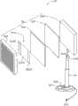
图1是本发明第一实施例提供的电取暖器的分解结构示意图。Fig. 1 is a schematic diagram of the exploded structure of the electric heater provided by the first embodiment of the present invention.
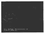
图2是本发明第一实施例提供的电取暖器中加热元件采用的碳纳米管拉膜的扫描电镜照片。Fig. 2 is a scanning electron micrograph of the carbon nanotube drawn film used in the heating element of the electric heater provided by the first embodiment of the present invention.
图3是本发明第一实施例提供的电取暖器中加热元件采用的碳纳米管絮化膜的扫描电镜照片。Fig. 3 is a scanning electron micrograph of the carbon nanotube flocculation film used in the heating element of the electric heater provided by the first embodiment of the present invention.
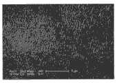
图4是本发明第一实施例提供的电取暖器中加热元件采用的碳纳米管碾压膜的扫描电镜照片。Fig. 4 is a scanning electron micrograph of the carbon nanotube laminated film used in the heating element of the electric heater provided by the first embodiment of the present invention.
图5是本发明第二实施例提供的电取暖器的分解结构示意图。Fig. 5 is a schematic diagram of an exploded structure of the electric heater provided by the second embodiment of the present invention.
图6是本发明第三实施例提供的电取暖器的分解结构示意图。Fig. 6 is a schematic diagram of an exploded structure of the electric heater provided by the third embodiment of the present invention.
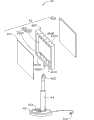
图7是本发明第四实施例提供的电取暖器的分解结构示意图。Fig. 7 is a schematic diagram of an exploded structure of the electric heater provided by the fourth embodiment of the present invention.
图8是本发明第五实施例提供的电取暖器的分解结构示意图。Fig. 8 is a schematic diagram of an exploded structure of the electric heater provided by the fifth embodiment of the present invention.
具体实施方式Detailed ways
以下将结合附图详细说明本发明实施例的电取暖器。The electric heater according to the embodiment of the present invention will be described in detail below with reference to the accompanying drawings.
请参见图1,为本发明第一实施例提供的一种电取暖器10。该电取暖器10包括一底座12,一支架14及安装于支架14上的机头16。Please refer to FIG. 1 , which shows an
所述底座12包括电源插头122和控制开关124。电源插头122用于电性连接外部电源,使整个电取暖器10处于通电状态。控制开关124用于控制电取暖器10的工作状态,包括电取暖器10的工作温度,工作时间及机头16的加热方向等。The
所述支架14用于支撑机头16以及连接该机头16和底座12。该支架14的一端设置有活动装置142。该活动装置142可控制机头16在水平方向上360度转动。该支架14的内部设置有电路系统(图未示),负责控制整个电取暖器10的工作。本实施例中,该支架14为一套管型支架,可通过调节该支架14的高度使机头16在竖直方向上移动。The
所述机头16包括一支撑结构160,一加热模组162,一保护结构164。所述支撑结构160包括一连接部1602,该连接部1602与支架14一端的活动装置142活动连接。该支撑结构160用于支撑和固定该加热模组162。该加热模组162位于保护结构164与支撑结构160之间。The
所述支撑结构160的形状不限,可以为无孔板状结构、多孔板状结构、或框状结构。所述支撑结构160的材料为绝缘材料,包括玻璃、陶瓷、塑料或木质材料。所述支撑结构160还可以为表面涂覆有绝缘材料的导电材料,如不锈钢、金属等。本实施例中,所述支撑结构160为一无孔板状结构。该支撑结构160的厚度不限,优选为1毫米~1厘米。当电取暖器10为一超薄结构时,该支撑结构160的厚度为1微米~1毫米。所述支撑结构160的大小不限,可根据加热空间的大小进行定制。The shape of the supporting
所述加热模组162设置于支撑结构160上,被支撑结构160支撑。所述加热模组162包括一加热元件1620及至少两个电极1622。所述加热元件162固定于支撑结构160的表面。加热元件162可通过粘结剂粘附于支撑结构160的表面,也可以通过机械固定方式如螺栓等固定于支撑结构160的表面。本实施例中,加热元件162通过粘结剂(图未示)粘附于支撑结构160的表面。所述至少两个电极1622与该加热元件1620电连接。所述至少两个电极1622可设置于加热元件160的同一表面或不同表面。本实施例中,至少两个电极1622位于加热元件160的同一表面,通过导电粘结剂固定,并通过电极引线(图未示)与支架14内部的电路系统电连接。The
所述加热元件1620包括一碳纳米管层状结构,该碳纳米管层状结构包括至少一层碳纳米管膜。当碳纳米管层状结构包括至少两层碳纳米管膜时,该至少两层碳纳米管膜层叠设置或并排设置。所述碳纳米管膜包括均匀分布的碳纳米管,碳纳米管之间通过范德华力紧密结合。该碳纳米管膜中的碳纳米管为无序或有序排列。这里的无序排列指碳纳米管的排列方向无规律,这里的有序排列指至少多数碳纳米管的排列方向具有一定规律。具体地,当碳纳米管膜包括无序排列的碳纳米管时,碳纳米管相互缠绕或者各向同性排列;当碳纳米管层状结构包括有序排列的碳纳米管时,碳纳米管沿一个方向或者多个方向择优取向排列。当该碳纳米管层状结构中碳纳米管有序排列时,该碳纳米管的排列方向可垂直于电极1622的排列方向。本实施例中,优选地,所述碳纳米管层状结构包括多个层叠设置的碳纳米管膜,且该碳纳米管层状结构的厚度优选为0.5纳米~1毫米。所述碳纳米管层状结构的单位面积热容小于2×10⁻⁴焦耳每平方厘米开尔文。优选地,所述碳纳米管层状结构的单位面积热容可以小于等于1.7×10⁻⁶焦耳每平方厘米开尔文。可以理解,碳纳米管层状结构的热响应速度与其厚度有关。在相同面积的情况下,碳纳米管层状结构的厚度越大,热响应速度越慢;反之,碳纳米管层状结构的厚度越小,热响应速度越快。The
所述碳纳米管膜可以为从一碳纳米管阵列中拉取所获得的碳纳米管拉膜。请参见图2,碳纳米管拉膜包括多个沿同一方向择优取向且平行于碳纳米管拉膜表面排列的碳纳米管。所述碳纳米管之间通过范德华力首尾相连。碳纳米管拉膜包括多个连续且定向排列的碳纳米管片段。该多个碳纳米管片段通过范德华力首尾相连。每一碳纳米管片段包括多个相互平行的碳纳米管,该多个相互平行的碳纳米管通过范德华力紧密连接。所述碳纳米管拉膜的厚度为0.5纳米~100微米,宽度与拉取该碳纳米管拉膜的碳纳米管阵列的尺寸有关,长度不限。可以理解的是,当该碳纳米管层状结构由碳纳米管拉膜组成,且该碳纳米管层状结构的厚度比较小时,例如小于10微米,该碳纳米管层状结构有很好的透明度,其透光率可以达到90%。当该电取暖器100的基板102和保温板104均采用透明材料时,采用透明的碳纳米管层状结构可以得到一透明的电取暖器,美观大方。该碳纳米管拉膜的面积不限,由拉出膜的碳纳米管阵列的大小决定。当碳纳米管阵列的尺寸较大时,可以拉出较大面积的碳纳米管拉膜,因此,可以制得面积较大的电取暖器,从而使该电取暖器具有较大的加热面积。The carbon nanotube film may be a carbon nanotube film drawn from a carbon nanotube array. Please refer to FIG. 2 , the drawn carbon nanotube film includes a plurality of carbon nanotubes preferentially oriented in the same direction and arranged parallel to the surface of the drawn carbon nanotube film. The carbon nanotubes are connected end to end by van der Waals force. The carbon nanotube stretched film includes a plurality of continuous and aligned carbon nanotube segments. The plurality of carbon nanotube segments are connected end to end by van der Waals force. Each carbon nanotube segment includes a plurality of parallel carbon nanotubes, and the plurality of parallel carbon nanotubes are closely connected by van der Waals force. The thickness of the drawn carbon nanotube film is 0.5 nanometers to 100 microns, the width is related to the size of the carbon nanotube array from which the drawn carbon nanotube film is drawn, and the length is not limited. It can be understood that when the carbon nanotube layered structure is composed of a carbon nanotube layered film, and the thickness of the carbon nanotube layered structure is relatively small, such as less than 10 microns, the carbon nanotube layered structure has a good Transparency, its light transmittance can reach 90%. When both the base plate 102 and the insulation board 104 of the electric heater 100 are made of transparent materials, a transparent electric heater can be obtained by using a transparent carbon nanotube layer structure, which is beautiful and elegant. The area of the carbon nanotube drawn film is not limited, and is determined by the size of the carbon nanotube array drawn from the film. When the size of the carbon nanotube array is large, a larger area of the carbon nanotube film can be drawn, so an electric heater with a larger area can be produced, so that the electric heater has a larger heating area.
所述碳纳米管絮化膜为通过一絮化方法形成的碳纳米管膜。请参见图3,该碳纳米管絮化膜包括相互缠绕且均匀分布的碳纳米管。所述碳纳米管之间通过范德华力相互吸引、缠绕,形成网络状结构。所述碳纳米管絮化膜各向同性。所述碳纳米管絮化膜的长度和宽度不限。由于在碳纳米管絮化膜中,碳纳米管相互缠绕,因此该碳纳米管絮化膜具有很好的柔韧性,且为一自支撑结构,可以弯曲折叠成任意形状而不破裂。所述碳纳米管絮化膜的面积及厚度均不限,厚度为1微米~1毫米,优选为100微米。The carbon nanotube flocculation film is a carbon nanotube film formed by a flocculation method. Please refer to FIG. 3 , the carbon nanotube flocculated film includes intertwined and evenly distributed carbon nanotubes. The carbon nanotubes attract and entangle with each other through van der Waals force to form a network structure. The carbon nanotube flocculation film is isotropic. The length and width of the carbon nanotube flocculated film are not limited. Since carbon nanotubes are intertwined in the carbon nanotube flocculated film, the carbon nanotube flocculated film has good flexibility and is a self-supporting structure that can be bent and folded into any shape without breaking. The area and thickness of the carbon nanotube flocculated film are not limited, and the thickness is 1 micron to 1 mm, preferably 100 microns.
所述碳纳米管膜还可以为通过碾压一碳纳米管阵列形成的碳纳米管碾压膜。该碳纳米管碾压膜包括均匀分布的碳纳米管,碳纳米管沿同一方向或不同方向择优取向排列。碳纳米管也可以是各向同性的。所述碳纳米管碾压膜中的碳纳米管相互部分交叠,并通过范德华力相互吸引,紧密结合。所述碳纳米管碾压膜中的碳纳米管与形成碳纳米管阵列的生长基底的表面形成一夹角β,其中,β大于等于0度且小于等于15度(0≤β≤15°)。依据碾压的方式不同,该碳纳米管碾压膜中的碳纳米管具有不同的排列形式。请参阅图4,当沿同一方向碾压时,碳纳米管沿一固定方向择优取向排列。可以理解,当沿不同方向碾压时,碳纳米管可沿多个方向择优取向排列。该碳纳米管碾压膜厚度不限,优选为为1微米~1毫米。该碳纳米管碾压膜的面积不限,由碾压出膜的碳纳米管阵列的大小决定。当碳纳米管阵列的尺寸较大时,可以碾压制得较大面积的碳纳米管碾压膜,因此,可以制得面积较大的电取暖器,从而使该电取暖器具有较大的加热面积。The carbon nanotube film can also be a carbon nanotube rolled film formed by rolling a carbon nanotube array. The carbon nanotube rolling film includes uniformly distributed carbon nanotubes, and the carbon nanotubes are preferentially oriented in the same direction or in different directions. Carbon nanotubes can also be isotropic. The carbon nanotubes in the carbon nanotube rolling film partially overlap each other, and are attracted to each other by van der Waals force, and are closely combined. The carbon nanotubes in the carbon nanotube rolling film form an angle β with the surface of the growth substrate forming the carbon nanotube array, where β is greater than or equal to 0 degrees and less than or equal to 15 degrees (0≤β≤15°) . According to different rolling methods, the carbon nanotubes in the carbon nanotube rolling film have different arrangement forms. Please refer to FIG. 4 , when rolled in the same direction, the carbon nanotubes are preferentially aligned along a fixed direction. It is understood that carbon nanotubes can be preferentially aligned in multiple directions when rolled in different directions. The thickness of the rolled carbon nanotube film is not limited, preferably 1 micron to 1 mm. The area of the carbon nanotube rolling film is not limited, and is determined by the size of the carbon nanotube array rolled out of the film. When the size of the carbon nanotube array is large, the carbon nanotube rolling film with a larger area can be rolled and pressed, so an electric heater with a larger area can be produced, so that the electric heater has a larger heating area.
所述至少两个电极1622设置于加热元件1620的表面。所述的至少两个电极1622可通过一导电粘结剂(图未示)设置于该加热元件1620的表面,导电粘结剂在实现电极1622更好地固定于加热元件1620的表面同时,还可以使电极1622与加热元件1620之间保持良好的电接触。该导电粘结剂可以为银胶。所述至少两个电极1622由导电材料制成,其形状不限,可为导电膜、金属片或者金属引线。优选地,该至少两个电极1622分别为一层导电膜。当电取暖器100为超薄的结构时,该导电膜的厚度为0.5纳米~100微米。该导电膜的材料可以为金属、合金、铟锡氧化物(ITO)、锑锡氧化物(ATO)、导电银胶、导电聚合物或导电性碳纳米管等。该金属或合金材料可以为铝、铜、钨、钼、金、钛、钕、钯、铯或其任意组合的合金。本实施例中,所述电极108的材料为金属钯膜,厚度为5微米。所述金属钯与碳纳米管具有较好的润湿效果,有利于所述电极1622与所述加热元件1620之间形成良好的电接触,减少欧姆接触电阻。所述至少两个电极1622分别通过电极引线(图未示)与支架14中的电路电连接。The at least two
所述电取暖器10可以包括多个电极与所述加热元件1620电连接,其数量不限,以通过控制不同的电极从而实现加热元件1620有选择的加热。该多个电极中任意两个电极可分别与外部电路电连接,使电连接于该两个电极之间的加热元件1620工作。优选地,该多个电极中的任意两个相邻的电极通过电极引线分别与外部电源电连接,即交替间隔设置的电极同时接正极或负极,使每两个相邻的电极之间的加热元件相互并联,从而可以减小加热元件的方块电阻。The
所述保护结构164用于保护加热元件1620,防止加热元件1620因外界污染遭受损坏,或者防止该电取暖器100在使用时造成触电伤害。所述保护结构164的材料不限,可以为绝缘材料也可以为导电材料,只需满足其具有较好的耐热性能即可。所述保护结构164的材料可选择为导电材料,如金属,也可为绝缘材料,如塑胶、塑料等。所述金属包括不锈钢、碳钢、铜、镍、钛、锌及铝等中的一种或多种。可以理解的是,当保护结构164的材料为绝缘材料时,其可与加热元件1620和至少两个电极1622直接接触。当保护结构1620的材料为导电材料时,应确保保护结构164与加热元件1620间隔绝缘设置。所述保护结构164可为一多孔结构,如栅网,也可为一无孔结构,如玻璃板等。本实施例中,所述保护结构164为一具有栅网结构的凹槽。保护结构164的四周固定于支撑结构160的四周。所述保护结构164与支撑结构160之间形成一空间,所述加热模组162设置于该空间内部,加热模组162与保护结构162之间间隔设置。所述保护结构164的固定方式不限,可通过螺栓、粘结、铆接等方式固定,本实施例中,保护结构通过四个螺孔(图未示)固定于支撑结构160上。由于该保护结构164与加热元件1620间隔一定空间设置,所以,该保护结构164的材料可以为导电材料。可以理解的是,导电材料一般具有较好的导热性,当保护结构164的材料为导电材料时,该电取暖器10具有较好的散热效果和较高的加热效率。The
本实施例提供的电取暖器10,由于加热元件1620中采用碳纳米管层状结构,具有以下优点:其一,该碳纳米管层状结构包括多个碳纳米管,碳纳米管的密度较小,因此该电取暖器10质量较小,便于应用。其二,且由于该碳纳米管层状结构包括至少一层碳纳米管膜,该碳纳米管膜的厚度最小可以达到0.5纳米,因此,该电取暖器10可做成超薄的结构,应用时占用的空间较小,特别适合在空间较小的房间使用且较为美观。其三,碳纳米管层状结构由碳纳米管膜构成,由于可以较为简单的获得面积较大的碳纳米管膜,因此,该碳纳米管层状结构可以具有较大的面积,可以以简单的工艺获得加热面积较大的电取暖器10。其四,该碳纳米管层状结构具有黑体结构,其热量以热辐射电磁波的形式传递,能发出红外线电磁波。The
请参见图5,本发明第二实施例提供一种电取暖器20。该电取暖器20包括一底座22,一支架24及安装于支架24上的机头26。所述底座22包括电源插头222和控制开关224。所述支架24用于支撑机头26。该支架24的一端设置有活动装置242。该活动装置242可控制机头26在水平方向上360度转动。该支架24的内部设置有电路系统(图未示),负责控制整个电取暖器20的工作。该支架24的高度可调,因此,机头26可在竖直方向的移动。所述机头26包括一支撑结构260,一加热模组262,一保护结构264。所述支撑结构260包括一连接部2602,该连接部2602与支架204一端的活动装置242活动连接。该加热模组262位于支撑结构260与保护结构264之间。该加热模组262包括一加热元件2620及两个电极2622。该加热元件2620包括一碳纳米管层状结构。Referring to FIG. 5 , the second embodiment of the present invention provides an
本实施例所提供的电取暖器20与第一实施例提供的电取暖器100的结构基本相同,其区别在于,本实施例所提供的电取暖器200包括一反射层212及一绝缘层214设置于支撑结构260与加热模组262之间。所述反射层212设置于支撑结构260的表面,所述绝缘层214设置于反射层212的表面,所述加热模组262设置于绝缘层214的表面。即,支撑结构260、反射层212,绝缘层214和加热模组262依次设置,形成一多层结构。The structure of the
所述热反射层212用于反射加热元件2620所发出的热量,使其热量有效地朝远离支撑结构260的一侧发散,实现电取暖器20单面加热。热反射层212的材料可为白色绝缘材料,如:金属氧化物、金属盐、或陶瓷等。热反射层212也可为导电材料,如金属,包括银、铝、铝、金或合金等。热反射层212的厚度不限,优选为1微米~1毫米。本实施例中,热反射层212的材料为铝箔,其厚度为0.1毫米。The
所述绝缘层214用于使热反射层212和加热元件2620绝缘设置。可以理解,当热反射层212的材料为绝缘材料时,无需设置绝缘层214于热反射层212和加热元件2620之间。所述绝缘层的材料为绝缘材料,如陶瓷、塑料、玻璃等。绝缘层214的厚度不限,优选为1微米~1毫米。本实施例中,绝缘层214的材料为陶瓷,其厚度为10微米。所述绝缘层214靠近加热元件2620的表面可进一步包括由至少一个凹部或凸部组成的图形化结构,所述加热元件2620在该凹部或凸部对应的位置至少部分悬空设置。The insulating
本实施例所提供的电取暖器20在支撑结构260与加热元件2620之间设置一热反射层212,使加热元件206产生的热量朝远支撑结构260的一侧发散。加热元件2620包括一碳纳米管层状结构,该碳纳米管层状结构包括多个碳纳米管,可以理解,碳纳米管产生的热量主要以电磁波的形式传播,对于以电磁波形式传播的热量,热反射层212可以有效的将热量反射至另一方向,提高了该电取暖器20的单面加热的效率,同时可以保护所述支撑结构260,防止当碳纳米管层状结构所产生的温度较高时损坏支撑结构260。In the
请参见图6,本发明第三实施例提供一种电取暖器30。该电取暖器30包括一底座32,一支架34及安装于支架34上的机头36。所述底座32包括电源插头322和控制开关324。所述支架34用于支撑机头36。该支架34的一端设置有活动装置342。该活动装置342可控制机头36在水平方向上360度转动。该支架314的高度可调,也可以使机头36在竖直方向上移动。该支架34的内部设置有电路系统(图未示),负责控制整个电取暖器30的工作。Referring to FIG. 6 , the third embodiment of the present invention provides an
所述机头36包括一支撑结构360,一第一加热模组362,一第一保护结构364。所述支撑结构360包括一连接部3602,该连接部3602与支架304一端的活动装置3042活动连接。该支撑结构360包括一第一表面3604和与该第一表面3604相对的第二表面3606。该第一加热模组362设置于支撑结构360的第一表面3604,位于第一表面3604与第一保护结构364之间。该第一加热模组362包括一第一加热元件3620及两个第一电极3622。该第一加热元件3620包括一碳纳米管层状结构。The
本实施例所提供的电取暖器30与第一实施例提供的电取暖器10的结构基本相同,其区别在于,本实施例所提供的电取暖器30进一步包括一第二加热模组366及一第二保护结构368。该第二加热模组366及一第二保护结构保护结构368皆设置于所述机头36上。所述第二加热模组366设置于支撑结构360的第二表面3606,位于第二表面3606与第二保护结构368之间。所述第二加热模组366包括一第二加热元件3620及两个第二电极3622。第二加热元件3620包括一碳纳米管层状结构。第二加热模组366的结构与第一加热模组362的结构相同。所述第二保护结构368的结构与第一保护结构364的结构相同。The structure of the
本实施例所提供的电取暖器30,通过设置第二加热模组366可以使该电取暖器30实现较高效率的双面加热,具有较大的有效加热范围,适合在办公室、酒店大堂或者会议室等场所应用。The
请参见图7,本发明第四实施例提供一种电取暖器40。该电取暖器40包括一底座42,一支架44及安装于支架44上的机头46。所述底座42包括电源插头422和控制开关424。所述支架44用于支撑机头46。该支架44的一端设置有活动装置442。该活动装置442可控制机头46在水平方向上360度转动。该支架44的内部设置有电路系统(图未示),负责控制整个电取暖器40的工作。所述机头46包括一支撑结构460,一加热模组462,一第一保护结构464及以第二保护结构468。所述支撑结构460包括一连接部4602,该连接部4602与支架404一端的活动装置4042活动连接。该加热模组462设置于支撑结构460上。该加热模组462包括一加热元件4620及四个电极4622。该加热元件4620包括一碳纳米管层状结构,该碳纳米管层状结构的厚度小于10微米。Referring to FIG. 7 , the fourth embodiment of the present invention provides an
本实施例所提供的电取暖器40与第一实施例所提供的电取暖器10的结构基本相同,其区别在于支撑结构460的形状、加热模组462与支撑结构460的位置关系以及电极4622的数量与第一实施例所提供的电取暖器10不同。The structure of the
本实施例中,所述支撑结构460为一框架结构,其包括一第一侧板4604及与该第一侧板4604相对的第二侧板4606。所述第一侧板4604和第二侧板4606上包括若干数目相同的孔4608,4610,且第一侧板4604上的孔4608和第二侧板4610上的孔一一对应。第一侧板4604上的孔4608和第二侧板4610上的孔的数量与加热模组462中电极4622的数量相等。第一侧板4604上的相邻的孔4608之间的距离相等,第二侧板4606上的相邻的孔4610之间的距离相等。本实施例中,电极4622的数量为四个,因此,第一侧板4604上的孔4608和第二侧板4606上的孔4610的数量分别为四个。In this embodiment, the supporting
加热模组462的四个电极4622均为金属丝,每个电极4622的两端分别固定于第一侧板4604上的孔4608和与该孔对应的第二侧板4606上的孔4610。该四个电极4622之间的距离相等且相互平行。所述加热元件4620设置于电极4622上,电极4622位于加热元件4620的表面。本实施例中电极4622支撑该加热元件4620,使加热元件4620悬空设置。该四个电极4622通过电极引线分别与支架44内部的电路系统电连接。The four
所述支撑结构460设置于所述第一保护结构464和所述第二保护结构468之间。所述第一保护结构464和第二保护结构468分别为透明玻璃板。由于支撑结构460为一框架结构,第一保护结构464、第二保护结构468与支撑结构460形成一空间,所述加热模组462位于该空间内部。The
本实施例所提供的电取暖器40加热元件4620通过电极4622悬空设置,由于加热元件4622为一碳纳米管层状结构,该碳纳米管层状结构的厚度小于10微米,具有很好的透明度,其透光率可以达到90%,第一/第二保护结构464,468分别为透明玻璃板,因此,电取暖器40为一透明电取暖器,应用时不会阻挡视线且美观大方。且,由于加热元件4620悬空设置,加热元件4620可以朝两个方向有效的散发热量,该电取暖器40的加热效率较高。The
请参见图8,本发明第五实施例提供一种电取暖器50。该电取暖器50包括一底座52,一支架54及安装于支架54上的机头56。所述底座52包括电源插头522和控制开关524。所述支架54用于支撑机头56。该支架54的一端设置有活动装置542。该活动装置542可控制机头56在水平方向上360度转动。该支架54的内部设置有电路系统(图未示),负责控制整个电取暖器50的工作。所述机头56包括一支撑结构560,一加热模组562,一保护结构564。所述支撑结构560包括一连接部5602,该连接部5602与支架504一端的活动装置5042活动连接。该加热模组562位于支撑结构560与保护结构564之间。该加热模组562包括一加热元件5620及两个电极5622。所述加热元件5620位于支撑结构560的表面。该加热元件5620包括一碳纳米管层状结构。Referring to FIG. 8 , the fifth embodiment of the present invention provides an
本实施例所提供的电取暖器50与第一实施例提供的电取暖器100的结构基本相同,其区别在于,本实施例所提供的电取暖器500中的支撑结构560靠近加热元件5620的表面进一步图形化,包括至少一个朝向加热元件5620开口的凹部或者至少一个朝向加热元件凸起的凸部,使该加热元件5620通过该至少一个凹部或凸部至少部分悬空设置。凹部或凸部的形状不限。所述凹部的最大深度小于或等于支撑结构560的厚度,当凹部的最大深度等于支撑结构560的厚度时,该凹部为一通槽。当凹部的最大深度小于支撑结构560的厚度时,该凹部为一盲槽。所述凸部与支撑结构560可以一体成型,也可以非一体成型。该支撑结构560靠近加热元件5620的表面可包括多个凹部或凸部组成的图形化的结构,该图形化结构的形状不限,优选地,该图形化的结构包括多个间隔设置点状结构或多个线状结构,即使支撑结构560与加热元件5620之间为点接触或线接触。进一步地,该多个线状结构可相互平行设置。该点状结构可为面积较小的圆形、方形、三角形或其他不规则形状。该线状结构可为宽度较小的带状、条状。该多个凹部或凸部可均匀分布或者随机分布,因此,该点状结构或线状结构可均匀分布或者随机分布。本实施例中,支撑结构560包括多个圆柱状的凹部5604,该圆柱状的凹部5604的深度等于支撑结构560的厚度,即该凹部5604为通孔结构。The structure of the
本实施例所提供的电取暖器500通过在支撑结构560的表面设置至少一个朝向加热元件5620开口的凹部或者至少一个朝向加热元件凸起的凸部,可以使加热元件5602对应凹部或凸部的位置至少部分悬空设置,由于加热元件5602包括一碳纳米管层状结构,该碳纳米管层状结构产生的热量以热辐射电磁波的形式传递,当碳纳米管层状结构悬空设置时,加热元件5602具有较高的加热效率。The electric heater 500 provided in this embodiment can make the
另外,本领域技术人员还可在本发明精神内做其他变化,当然,这些依据本发明精神所做的变化,都应包含在本发明所要求保护的范围之内。In addition, those skilled in the art can also make other changes within the spirit of the present invention. Of course, these changes made according to the spirit of the present invention should be included within the scope of protection claimed by the present invention.
Claims (17)
Priority Applications (3)
| Application Number | Priority Date | Filing Date | Title |
|---|---|---|---|
| CN2009101901752ACN102012061B (en) | 2009-09-08 | 2009-09-08 | Electric warmer |
| US12/769,805US20110056929A1 (en) | 2009-09-08 | 2010-04-29 | Electric heater |
| US14/297,626US9468044B2 (en) | 2009-09-08 | 2014-06-06 | Carbon nanotube based electric heater with supporter having blind holes or protrusions |
Applications Claiming Priority (1)
| Application Number | Priority Date | Filing Date | Title |
|---|---|---|---|
| CN2009101901752ACN102012061B (en) | 2009-09-08 | 2009-09-08 | Electric warmer |
Publications (2)
| Publication Number | Publication Date |
|---|---|
| CN102012061A CN102012061A (en) | 2011-04-13 |
| CN102012061Btrue CN102012061B (en) | 2012-11-21 |
Family
ID=43646894
Family Applications (1)
| Application Number | Title | Priority Date | Filing Date |
|---|---|---|---|
| CN2009101901752AExpired - Fee RelatedCN102012061B (en) | 2009-09-08 | 2009-09-08 | Electric warmer |
Country Status (2)
| Country | Link |
|---|---|
| US (2) | US20110056929A1 (en) |
| CN (1) | CN102012061B (en) |
Families Citing this family (10)
| Publication number | Priority date | Publication date | Assignee | Title |
|---|---|---|---|---|
| DE102007004953A1 (en)* | 2007-01-26 | 2008-07-31 | Tesa Ag | heating element |
| CN101880035A (en) | 2010-06-29 | 2010-11-10 | 清华大学 | carbon nanotube structure |
| CN103379681B (en)* | 2012-04-28 | 2016-03-30 | 清华大学 | Heating resistance pad |
| CN103697525A (en)* | 2013-12-30 | 2014-04-02 | 吴江菀坪隆华机电制造有限公司 | Heater with adjustable heat dissipation angle |
| CA2955361A1 (en) | 2014-07-18 | 2016-01-21 | Kim Edward ELVERUD | Resistive heater |
| CA3002539A1 (en)* | 2015-10-23 | 2017-04-27 | Nanocomp Technologies, Inc. | Directed infrared radiator article |
| GB2551250B (en)* | 2016-04-15 | 2022-02-09 | Levidian Nanosystems Ltd | Heater elements, heat exchangers and heater element arrays |
| CN109392199A (en)* | 2017-08-14 | 2019-02-26 | 有几园生物科技股份有限公司 | Plane far infrared ray irradiator |
| ES2703973B2 (en)* | 2017-09-13 | 2019-12-18 | Fundacion Para La Promocion De La Innovacion Investig Y Desarrollo Tecnologico En La Industria De Au | Radiant heating device and manufacturing procedure |
| US11930565B1 (en)* | 2021-02-05 | 2024-03-12 | Mainstream Engineering Corporation | Carbon nanotube heater composite tooling apparatus and method of use |
Citations (5)
| Publication number | Priority date | Publication date | Assignee | Title |
|---|---|---|---|---|
| CN2143743Y (en)* | 1992-09-30 | 1993-10-13 | 倪梓明 | Mushroom shape double radiation surface infra red eletric heating device |
| CN2213303Y (en)* | 1994-12-23 | 1995-11-22 | 吴踪良 | Automatic limiting and control temp. electrothermal board |
| CN2469650Y (en)* | 2001-01-19 | 2002-01-02 | 内蒙古鑫桥建筑工程有限公司第一分公司 | Temp. controlled electric heating plate |
| WO2004082333A1 (en)* | 2003-03-14 | 2004-09-23 | Nanotech Co., Ltd. | Seat-like heating units with porous plate-shaped electrode |
| CN2694150Y (en)* | 2003-12-17 | 2005-04-20 | 张和君 | Heating device and electric heating device using the same |
Family Cites Families (8)
| Publication number | Priority date | Publication date | Assignee | Title |
|---|---|---|---|---|
| US1710512A (en)* | 1927-07-15 | 1929-04-23 | Anderson Pitt Corp | Heating element |
| US6683783B1 (en)* | 1997-03-07 | 2004-01-27 | William Marsh Rice University | Carbon fibers formed from single-wall carbon nanotubes |
| JP3794116B2 (en)* | 1997-08-06 | 2006-07-05 | 株式会社デンソー | Heat exchanger for heating |
| CN1183805C (en)* | 1999-12-10 | 2005-01-05 | 热离子体系国际公司 | Thermoplastic laminate fabric heater and methods for making same |
| US7158716B2 (en)* | 2002-12-18 | 2007-01-02 | Lasko Holdings, Inc. | Portable pedestal electric heater |
| KR100749886B1 (en)* | 2006-02-03 | 2007-08-21 | (주) 나노텍 | Heating element using carbon nanotube |
| US7576305B2 (en)* | 2006-09-22 | 2009-08-18 | Catem Gmbh & Co. Kg | Heat-generating element of a heating device |
| KR20090033138A (en)* | 2007-09-28 | 2009-04-01 | 칭화 유니버시티 | Cotton heating source |
- 2009
- 2009-09-08CNCN2009101901752Apatent/CN102012061B/ennot_activeExpired - Fee Related
- 2010
- 2010-04-29USUS12/769,805patent/US20110056929A1/ennot_activeAbandoned
- 2014
- 2014-06-06USUS14/297,626patent/US9468044B2/enactiveActive
Patent Citations (5)
| Publication number | Priority date | Publication date | Assignee | Title |
|---|---|---|---|---|
| CN2143743Y (en)* | 1992-09-30 | 1993-10-13 | 倪梓明 | Mushroom shape double radiation surface infra red eletric heating device |
| CN2213303Y (en)* | 1994-12-23 | 1995-11-22 | 吴踪良 | Automatic limiting and control temp. electrothermal board |
| CN2469650Y (en)* | 2001-01-19 | 2002-01-02 | 内蒙古鑫桥建筑工程有限公司第一分公司 | Temp. controlled electric heating plate |
| WO2004082333A1 (en)* | 2003-03-14 | 2004-09-23 | Nanotech Co., Ltd. | Seat-like heating units with porous plate-shaped electrode |
| CN2694150Y (en)* | 2003-12-17 | 2005-04-20 | 张和君 | Heating device and electric heating device using the same |
Also Published As
| Publication number | Publication date |
|---|---|
| US20140284319A1 (en) | 2014-09-25 |
| US20110056929A1 (en) | 2011-03-10 |
| CN102012061A (en) | 2011-04-13 |
| US9468044B2 (en) | 2016-10-11 |
Similar Documents
| Publication | Publication Date | Title |
|---|---|---|
| CN102012061B (en) | Electric warmer | |
| CN102012060B (en) | Wall type electric warmer | |
| CN102162294B (en) | Heating floor tile and heating floor using the same | |
| CN102006542B (en) | Sound generating device | |
| CN101848564B (en) | Heating element | |
| CN101894903B (en) | photoelectric conversion device | |
| CN101616513A (en) | line heat source | |
| CN101636001A (en) | Cubic heat source | |
| TWI395913B (en) | Wall-mounted electric heater | |
| TWI487427B (en) | Electric heater | |
| TWI487426B (en) | Electric heater | |
| CN101636007B (en) | Plane heat source | |
| CN101636004A (en) | Plane heat source | |
| TWI462630B (en) | Surface heat source | |
| CN101636011B (en) | Hollow heat source | |
| CN101636008A (en) | Plane heat source | |
| CN101616512B (en) | Line heat source | |
| TWI500842B (en) | Heating the floor tile and the heated floor using the heated floor tile | |
| TW201240485A (en) | Thermal acoustic device and electric device | |
| CN2779783Y (en) | Electric heating membrane | |
| CN102026079B (en) | Sound-producing device | |
| CN101636002B (en) | Three-dimensional heat source | |
| TW201240484A (en) | Thermal acoustic device and electric device | |
| TWI386363B (en) | Linear heater | |
| TWI465145B (en) | Hollow heat source |
Legal Events
| Date | Code | Title | Description |
|---|---|---|---|
| C06 | Publication | ||
| PB01 | Publication | ||
| C10 | Entry into substantive examination | ||
| SE01 | Entry into force of request for substantive examination | ||
| CI01 | Publication of corrected invention patent application | Correction item:Applicant|Address|Co-applicant Correct:Tsinghua University|100084. Haidian District 1, Tsinghua Yuan, Beijing, Tsinghua University, Room 401, research center of Tsinghua Foxconn nanometer science and technology|Hung Fujin Precision Industrial (Shenzhen) Co., Ltd. False:Hongfujin Precision Industry (Shenzhen) Co., Ltd.|518109 Guangdong city of Shenzhen province Baoan District Longhua Town Industrial Zone tabulaeformis tenth East Ring Road No. 2 two Number:15 Volume:27 | |
| CI02 | Correction of invention patent application | Correction item:Applicant|Address|Co-applicant Correct:Tsinghua University|100084. Haidian District 1, Tsinghua Yuan, Beijing, Tsinghua University, Room 401, research center of Tsinghua Foxconn nanometer science and technology|Hung Fujin Precision Industrial (Shenzhen) Co., Ltd. False:Hongfujin Precision Industry (Shenzhen) Co., Ltd.|518109 Guangdong city of Shenzhen province Baoan District Longhua Town Industrial Zone tabulaeformis tenth East Ring Road No. 2 two Number:15 Page:The title page Volume:27 | |
| ERR | Gazette correction | Free format text:CORRECT: APPLICANT; ADDRESS; CO-APPLICANT; FROM: HONGFUJIN PRECISION INDUSTRY (SHENZHEN) CO., LTD.;518109 NO. 2, DONGHUAN 2ND ROAD, YOUSONG INDUSTRIAL ZONE 10, LONGHUA TOWN, BAO'AN DISTRICT, SHENZHEN CITY, GUANGDONG PROVINCE TO: TSINGHUA UNIVERSITY;100084 ROOM 401, TSINGHUA-FOXCONN NANOTECHNOLOGY RESEARCH CENTER, TSINGHUA UNIVERSITY, NO. 1, TSINGHUA PARK, HAIDIAN DISTRICT, BEIJING; HONGFUJIN PRECISION INDUSTRY (SHENZHEN) CO., LTD. | |
| C14 | Grant of patent or utility model | ||
| GR01 | Patent grant | ||
| CF01 | Termination of patent right due to non-payment of annual fee | ||
| CF01 | Termination of patent right due to non-payment of annual fee | Granted publication date:20121121 |