CN102006820A - Support device for sensors and/or actuators that can be part of a wireless network of sensors/actuators - Google Patents
Support device for sensors and/or actuators that can be part of a wireless network of sensors/actuatorsDownload PDFInfo
- Publication number
- CN102006820A CN102006820ACN2009801132575ACN200980113257ACN102006820ACN 102006820 ACN102006820 ACN 102006820ACN 2009801132575 ACN2009801132575 ACN 2009801132575ACN 200980113257 ACN200980113257 ACN 200980113257ACN 102006820 ACN102006820 ACN 102006820A
- Authority
- CN
- China
- Prior art keywords
- sensor
- base body
- sensors
- actuators
- connection
- Prior art date
- Legal status (The legal status is an assumption and is not a legal conclusion. Google has not performed a legal analysis and makes no representation as to the accuracy of the status listed.)
- Granted
Links
Images


Classifications
- G—PHYSICS
- G01—MEASURING; TESTING
- G01D—MEASURING NOT SPECIALLY ADAPTED FOR A SPECIFIC VARIABLE; ARRANGEMENTS FOR MEASURING TWO OR MORE VARIABLES NOT COVERED IN A SINGLE OTHER SUBCLASS; TARIFF METERING APPARATUS; MEASURING OR TESTING NOT OTHERWISE PROVIDED FOR
- G01D11/00—Component parts of measuring arrangements not specially adapted for a specific variable
- G01D11/30—Supports specially adapted for an instrument; Supports specially adapted for a set of instruments
- A—HUMAN NECESSITIES
- A61—MEDICAL OR VETERINARY SCIENCE; HYGIENE
- A61B—DIAGNOSIS; SURGERY; IDENTIFICATION
- A61B5/00—Measuring for diagnostic purposes; Identification of persons
- A61B5/0002—Remote monitoring of patients using telemetry, e.g. transmission of vital signals via a communication network
- A—HUMAN NECESSITIES
- A61—MEDICAL OR VETERINARY SCIENCE; HYGIENE
- A61B—DIAGNOSIS; SURGERY; IDENTIFICATION
- A61B5/00—Measuring for diagnostic purposes; Identification of persons
- A61B5/68—Arrangements of detecting, measuring or recording means, e.g. sensors, in relation to patient
- A61B5/6801—Arrangements of detecting, measuring or recording means, e.g. sensors, in relation to patient specially adapted to be attached to or worn on the body surface
- A61B5/6802—Sensor mounted on worn items
- A61B5/681—Wristwatch-type devices
- A—HUMAN NECESSITIES
- A61—MEDICAL OR VETERINARY SCIENCE; HYGIENE
- A61B—DIAGNOSIS; SURGERY; IDENTIFICATION
- A61B5/00—Measuring for diagnostic purposes; Identification of persons
- A61B5/68—Arrangements of detecting, measuring or recording means, e.g. sensors, in relation to patient
- A61B5/6801—Arrangements of detecting, measuring or recording means, e.g. sensors, in relation to patient specially adapted to be attached to or worn on the body surface
- A61B5/683—Means for maintaining contact with the body
- A61B5/6831—Straps, bands or harnesses
- A—HUMAN NECESSITIES
- A61—MEDICAL OR VETERINARY SCIENCE; HYGIENE
- A61B—DIAGNOSIS; SURGERY; IDENTIFICATION
- A61B2560/00—Constructional details of operational features of apparatus; Accessories for medical measuring apparatus
- A61B2560/04—Constructional details of apparatus
- A61B2560/0443—Modular apparatus
- A61B2560/045—Modular apparatus with a separable interface unit, e.g. for communication
- A—HUMAN NECESSITIES
- A61—MEDICAL OR VETERINARY SCIENCE; HYGIENE
- A61B—DIAGNOSIS; SURGERY; IDENTIFICATION
- A61B2560/00—Constructional details of operational features of apparatus; Accessories for medical measuring apparatus
- A61B2560/04—Constructional details of apparatus
- A61B2560/0475—Special features of memory means, e.g. removable memory cards
- A—HUMAN NECESSITIES
- A61—MEDICAL OR VETERINARY SCIENCE; HYGIENE
- A61B—DIAGNOSIS; SURGERY; IDENTIFICATION
- A61B2562/00—Details of sensors; Constructional details of sensor housings or probes; Accessories for sensors
- A61B2562/08—Sensors provided with means for identification, e.g. barcodes or memory chips
Landscapes
- Health & Medical Sciences (AREA)
- Life Sciences & Earth Sciences (AREA)
- Engineering & Computer Science (AREA)
- Physics & Mathematics (AREA)
- General Health & Medical Sciences (AREA)
- Pathology (AREA)
- Biomedical Technology (AREA)
- Heart & Thoracic Surgery (AREA)
- Medical Informatics (AREA)
- Molecular Biology (AREA)
- Surgery (AREA)
- Animal Behavior & Ethology (AREA)
- Biophysics (AREA)
- Public Health (AREA)
- Veterinary Medicine (AREA)
- Computer Networks & Wireless Communication (AREA)
- General Physics & Mathematics (AREA)
- Measuring And Recording Apparatus For Diagnosis (AREA)
- Arrangements For Transmission Of Measured Signals (AREA)
- Selective Calling Equipment (AREA)
- Control Or Security For Electrophotography (AREA)
- Accessory Devices And Overall Control Thereof (AREA)
- Facsimiles In General (AREA)
- Retarders (AREA)
- Control And Safety Of Cranes (AREA)
Abstract
Translated fromChinese
Description
Translated fromChinese技术领域technical field
本发明涉及监视和控制传感器和/或致动器的无线网络的装置。具体地,该装置可应用在涉及无线体域网(WBAN)或无线体传感器网(WBSN)的生物医学领域中,以通过病人可佩带的传感器和/或致动器监视生理参数。The invention relates to a device for monitoring and controlling a wireless network of sensors and/or actuators. In particular, the device can be applied in the field of biomedicine involving wireless body area network (WBAN) or wireless body sensor network (WBSN) to monitor physiological parameters through patient wearable sensors and/or actuators.
背景技术Background technique
在针对病人的传统监视仪器中,已知为分别的专用装置提供每个记录的参数的是巨大且昂贵的系统。为此原因,可仅由医院或健康中心执行监视或传感过程。In conventional monitoring instruments for patients, it is known that a separate dedicated device for each recorded parameter is a bulky and expensive system. For this reason, monitoring or sensing procedures may only be performed by hospitals or health centers.
在这种类型的监视仪器中,适合存储和传输数据的便携装置与适合检测生理参数的传感器之间的连接通常是有线连接。特别是,由于线缆限制病人的移动,因此与病人皮肤接触的这样的传感器妨碍了病人。In this type of monitoring instrumentation, the connection between a portable device suitable for storing and transmitting data and a sensor suitable for detecting a physiological parameter is usually a wired connection. In particular, such sensors in contact with the patient's skin hinder the patient since the cable restricts the patient's movement.
已知通过使用无线通信和通过低功耗电技术移除有线连接。特别地,已知网络具有传感结点,每个传感结点都具有自己的电池元件,并且每个都在病人身体上安置,传感结点能够传感不同生理参数,从而存储所述参数,和/或用无线方式将所述参数传给更强功效的装置,该更强功效装置能记录这些参数和/或将这些参数向远程的中央操作单元传送。It is known to remove wired connections by using wireless communication and by low power consumption electrical techniques. In particular, known networks have sensor nodes, each with its own battery element, and each placed on the patient's body, the sensor nodes are capable of sensing different physiological parameters, thereby storing said parameters, and/or wirelessly transmit said parameters to a more powerful device capable of recording and/or transmitting these parameters to a remote central operating unit.
具体地,在借助通常称为“无线传感器网”(WSN)的系统监视生理参数时使用这样的装置。In particular, such devices are used in monitoring physiological parameters by means of systems commonly referred to as "Wireless Sensor Networks" (WSN).
无线传感器网(WSN)是包含小结点的网络,小结点能够容纳传感器、在每个结点上执行一些计算步骤,并能通过合适的网络协议互相通信。这样的传感器网络为通常针对结点检测的数据的性质的应用开发。在生物医学领域,例如,测量若干数据,如温度、压力、ECG信号、移动、位置、血压等等。由于适合各类应用的多个特性,WSN平台是引人关注的。这些网络的主要特性是以下内容:A wireless sensor network (WSN) is a network consisting of small nodes that can house sensors, perform some computational steps on each node, and communicate with each other through a suitable network protocol. Such sensor networks are often developed for applications of the nature of the data detected by the nodes. In the biomedical field, for example, several data are measured, such as temperature, pressure, ECG signal, movement, position, blood pressure, etc. The WSN platform is attractive due to several features suitable for various applications. The main characteristics of these networks are the following:
-构成网络的结点的稳定性:根据特定的应用,结点具有减小的尺寸,该尺寸允许简单的安放;- Stability of the nodes constituting the network: according to the specific application, the nodes have a reduced size which allows easy placement;
-创建网络而不需要具有专用基础设施;- Create a network without having a dedicated infrastructure;
-低能量,是以可使用必须持续几年的电池的方式运转网络必需的;- low energy, necessary to run the network in a way that can use batteries that must last several years;
-结点和连接器的异质性;- Heterogeneity of nodes and connectors;
-单独结点的低计算能力和通信。- Low computing power and communication of individual nodes.
此外,该类网络是动态的,因为即使一些结点损坏,或如果结点的数量改变,或在缺少电池的情况下,或如果结点被置换,也没有和网络相关的问题。Furthermore, this type of network is dynamic because even if some nodes are damaged, or if the number of nodes changes, or in case of lack of battery, or if nodes are replaced, there are no problems associated with the network.
“无线体域网”(WBAN)或“无线体传感器网”(WBSN)的标准体系结构提供不同的传感器化且小型化结点,每个都称为“体传感器单元”(BSU),也称为终端装置,结点以无线方式连接到中心单元,该中心单元可由病人佩带或设置在病人附近,称为体中心单元(BCU)。The standard architecture of "Wireless Body Area Network" (WBAN) or "Wireless Body Sensor Network" (WBSN) provides different sensorized and miniaturized nodes, each called "Body Sensor Unit" (BSU), also known as As an end device, the nodes are wirelessly connected to a central unit that can be worn by or placed near the patient, called a body-centric unit (BCU).
特殊地,终端装置是网络的终端结点,这些终端结点与病人的身体接触,或设置在周围环境中,而且配备合适的传感器和/或致动器,从而执行监视功能和/或主动与病人交互的功能。In particular, terminal devices are the terminal nodes of the network which are in contact with the patient's body or which are placed in the surrounding environment and which are equipped with suitable sensors and/or actuators so as to perform monitoring functions and/or actively communicate with Patient interaction features.
许多BSU获得的数据通过BCU和互联网环境之间的连接可在线访问,该连接可通过不同技术获得,例如WLAN、GPRS、UMTS等等。Much of the data obtained by the BSU is accessible online through the connection between the BCU and the Internet environment, which is available through different technologies such as WLAN, GPRS, UMTS, etc.
这样,WBAN监视的病人可由医生或医院工作人员持续远程观察,以便防止可能的并发症。数据可周期性存储在专用服务器中,并且医生可在任何希望的时刻执行完全检查。在紧急情况下,由于可通过病人激活的警报,以及由于响应生理参数的任何无规律性的监视系统,可在短时间内进行适当测量。In this way, patients monitored by the WBAN can be continuously observed remotely by doctors or hospital staff in order to prevent possible complications. Data can be periodically stored in a dedicated server, and a doctor can perform a full examination at any desired moment. In an emergency situation, due to the alarm that can be activated by the patient, and due to the monitoring system responding to any irregularities in the physiological parameters, appropriate measurements can be made within a short time.
终端装置的限制/问题,以及市场上目前可获得的生物医学WBAN产品的通常限制/问题,可以是以下内容:Limitations/problems of end devices, and generally of biomedical WBAN products currently available in the market, can be the following:
-“关闭”的系统目前可用,其中用户,例如医生、护士或病人同样不能改变系统结构;- "closed" systems are currently available, where users, such as doctors, nurses or patients, cannot change the system structure as well;
-根据功能性设计和制造终端装置,该功能性不可由用户改变,除非生产商/提供商/供应商或高素质操作员帮助;- the terminal device is designed and manufactured according to a functionality which cannot be changed by the user, except with the assistance of the manufacturer/provider/supplier or a highly qualified operator;
-终端装置用取决于它安装的特殊传感器/致动器的单个功能定义和设计,没有增加或改变特别的测量和/或操作功能性的可能性(例如测量的参数的类型);- the terminal device is defined and designed with a single function depending on the particular sensor/actuator it is installed, without the possibility of adding or changing specific measurement and/or operational functionality (e.g. the type of parameter measured);
-传感器/致动器,和/或电池,是可或多或少由用户容易替换的唯一区块,但仅用非常相似的装置,即具有相同功能的装置替换。- The sensor/actuator, and/or the battery, are the only blocks that are more or less easily replaceable by the user, but only with very similar devices, ie with the same functionality.
由于制造用于测量确定的生理参数的终端装置不可由用户改变以便测量另一参数,因此这些问题包括限制和灵活性。这同样导致装置的不良利用,因为一旦系统完成它的功能,或参数不再被关注,那么整个装置完全释放它的效用并且不可经修改来执行不同功能。These problems include limitations and flexibility since an end device manufactured to measure a certain physiological parameter cannot be changed by the user in order to measure another parameter. This also leads to poor utilization of the device, because once the system completes its function, or parameters are no longer of interest, the entire device completely releases its utility and cannot be modified to perform a different function.
发明内容Contents of the invention
因此,本发明的特性是为传感器和/或致动器提供支持装置,所述传感器和/或致动器可以是传感器和/或致动器的无线网络的一部分,并提供在单结点中集成多个传感和/或致动组件的可能性。It is therefore characteristic of the present invention to provide support means for sensors and/or actuators which may be part of a wireless network of sensors and/or actuators and provided in a single node Possibility to integrate multiple sensing and/or actuating components.
本发明的另一特性是为传感器和/或致动器提供这样的支持装置,以便依靠病人可佩带的传感器和/或致动器监视生理参数,支持装置适合支持多个传感器和/或致动器,并且同时可通过粘合工具或其它连接系统容易地固定到人体,所述传感器和/或致动器可以是无线体域网(WBAN)或无线体传感器网(WBSN)的环境的一部分。Another feature of the present invention is to provide such support means for sensors and/or actuators to monitor physiological parameters by means of sensors and/or actuators wearable by the patient, the support means being adapted to support multiple sensors and/or actuators Sensors, and at the same time can be easily fixed to the human body by adhesive tools or other connection systems, the sensors and/or actuators can be part of the environment of Wireless Body Area Network (WBAN) or Wireless Body Sensor Network (WBSN).
本发明的特性也是为传感器和/或致动器提供支持装置,所述传感器和/或致动器可以是传感器和/或致动器的无线网络的一部分,该无线网络提供在单个点中集成可用于家庭自动化(domotic)或工业环境中的多个传感器和/或致动器的可能性。It is also a feature of the invention to provide support means for sensors and/or actuators which may be part of a wireless network of sensors and/or actuators which provides integration in a single point Multiple sensor and/or actuator possibilities that can be used in a domotic or industrial environment.
本发明的进一步的特性是为传感器和/或致动器提供支持装置,所述传感器和/或致动器可以是传感器和/或致动器的无线网络的一部分,其中无经验的用户可根据定制的需要选择和装配该装置的传感和/或致动器组件,该需要源自病人的情况,或源自对病人的先前检测或控制的结果。A further characteristic of the invention is to provide support means for sensors and/or actuators which may be part of a wireless network of sensors and/or actuators, wherein an inexperienced user may Customization requires the selection and assembly of the sensing and/or actuator components of the device, derived from the patient's condition, or from the results of previous testing or control of the patient.
本发明的另一特性是为传感器和/或致动器提供支持装置,所述传感器和/或致动器可以是传感器和/或致动器的无线网络的一部分,其中仅开发该装置的传感组件,以便该装置用容易且简单的连接最低限度侵入病人,并能够以用户友好的方式接合。Another characteristic of the invention is to provide support means for sensors and/or actuators, which may be part of a wireless network of sensors and/or actuators, wherein only the transmission of the means is developed. Sensitive components so that the device is minimally invasive to the patient with easy and simple connections and can be engaged in a user-friendly manner.
本发明的特性也是为传感器和/或致动器提供支持装置,所述传感器和/或致动器可以是传感器和/或致动器的无线网络的一部分,其中所述装置的长期成本低,以使终端用户可在不同时间购买替代每个佩带的和/或没有使用的区块以及通过引入其它区块而增加新功能性必需的传感组件,维持相同主构架。It is also a feature of the invention to provide support means for sensors and/or actuators, which may be part of a wireless network of sensors and/or actuators, wherein the long-term cost of the means is low, The same main architecture is maintained so that end users can purchase at different times the sensing components necessary to replace each worn and/or unused block and to add new functionality by introducing other blocks.
这些和其它目标通过针对传感和/或致动结点网络的结点元件的传感器和/或致动器的支持装置实现,所述支持装置包含:These and other objectives are achieved by support means for sensors and/or actuators of the nodal elements of the sensing and/or actuating nodal network, said support means comprising:
-具有多个面的基体,至少一个传感器和/或致动器以及供电区块可应用于所述基体;- a base body with a plurality of faces, to which base body at least one sensor and/or actuator and a power supply block can be applied;
-将所述基体固定到支持表面的固定工具;- fixing means for fixing said substrate to a supporting surface;
-在所述基体中,包含微处理器或微控制器的控制单元;- in said base body, a control unit comprising a microprocessor or microcontroller;
-在所述基体中的存储单元,所述存储单元与所述控制单元通信,并适合存储多个配置参数、固件和数据;- a memory unit in said base body, said memory unit being in communication with said control unit and adapted to store a plurality of configuration parameters, firmware and data;
-适合产生无线传感器网络的无线通信工具,该无线传感器网络使所述微处理器与远程单元通信,所述远程单元包含具有各自的传感器和/或致动器以及适合与所述基体交换数据的至少一个数据控制单元的其它基体,- a wireless communication means suitable for creating a wireless sensor network enabling said microprocessor to communicate with a remote unit comprising a device with respective sensors and/or actuators and suitable for exchanging data with said substrate other substrates of at least one data control unit,
所述装置的主要特性是The main characteristics of the device are
所述基体的至少两面是各传感器和/或致动器的连接面,以及at least two sides of the base body are connection surfaces for sensors and/or actuators, and
所述基体包含:The matrix includes:
-强制啮合工具,用于在所述传感器和/或致动器之间用所述基体的所述连接面构成强制啮合;- positive engagement means for forming a positive engagement between said sensors and/or actuators with said connecting surface of said base body;
-在所述强制啮合工具处的接口工具,用于构成所述传感器和/或致动器与所述控制单元之间的接口;- interface means at said positive engagement means for constituting an interface between said sensors and/or actuators and said control unit;
-识别工具,用于识别通过所述强制啮合工具与接口工具连接到所述基体的确定的传感器和/或致动器。- Identification means for identifying certain sensors and/or actuators connected to said base body via said positive engagement means and interface means.
具体地,所述无线通信工具设置在所述基体内。Specifically, the wireless communication tool is arranged in the base.
优选地,所述传感和/或致动结点的网络的所述结点元件具有在厘米范围中的减少的尺寸。然而,它的可伸缩体系结构允许它可能进一步小型化。Preferably, said junction elements of said network of sensing and/or actuation junctions have reduced dimensions in the centimeter range. However, its scalable architecture allows for possible further miniaturization.
有利地,所述基体具有平坦形状,具体是具有四个基本矩形的延长的连接面的平行六面体,其中构成所述传感器和/或致动器之间强制啮合的所述强制啮合工具中的至少一个处于所述矩形的连接面。Advantageously, said basic body has a flat shape, in particular a parallelepiped with four substantially rectangular elongated connecting faces, wherein at least one of said positive engagement means constituting said sensor and/or actuator One is on the connection side of the rectangle.
有利地,提供适配器元件,或“前端”元件,该元件可固定在所述连接面上,所述前端元件提供与至少一个对应传感器和/或致动器的强制啮合连接,其中所述适配器元件包含下面元件中的一个或其组合:Advantageously, an adapter element, or "front end" element is provided, which is fixable on said connection face, said front end element providing a positively engaged connection with at least one corresponding sensor and/or actuator, wherein said adapter element Contains one or a combination of the following elements:
-包含微处理器或微控制器的控制单元;- control units containing microprocessors or microcontrollers;
-信号调整仪器;- signal conditioning instruments;
-模/数和/或数/模转换器;- analog/digital and/or digital/analog converters;
-与所述基体的接口;- an interface with said substrate;
-识别装置;- identification means;
-与所述传感器和/或致动器的接口。- Interface with said sensors and/or actuators.
优选地,提供分别连接至少两个基体的桥接口元件,其中所述桥接口元件包含下面元件中的一个或其组合:Preferably, bridging interface elements respectively connecting at least two substrates are provided, wherein the bridging interface elements comprise one or a combination of the following elements:
-包含微处理器或微控制器的控制单元;- control units containing microprocessors or microcontrollers;
-与第一基体的第一接口;- a first interface with the first substrate;
-识别装置;- identification means;
-与第二基体的第二接口。- a second interface with the second substrate.
这样,通过桥接口元件,可能增加连接面的数量,并因此增加可连接的传感器和/或致动器的数量。此外,可能增加网络结点元件的功率和/或功能性。In this way, by means of the bridging interface element, it is possible to increase the number of connection surfaces and thus the number of connectable sensors and/or actuators. Furthermore, it is possible to increase the power and/or functionality of network node elements.
优选地,所述基体包含至少一个硬件输入端口,该端口适于辅助外部装置的连接,辅助外部装置例如是显示所述传感器已经测量的参数的显示器或存储器扩展装置等等。这样,通过该显示器例如显示数值,例如压力、温度等等,但同样可显示图像。相反,存储器扩展装置,可以是提高基体的存储或计算能力必需的,以及存储长期数据必需的,例如24/48小时的病人数据,以便在监视步骤结束时最后上载它们。Preferably, said base body comprises at least one hardware input port suitable for the connection of an auxiliary external device, such as a display or a memory expansion device or the like for displaying the parameters already measured by said sensor. In this way, for example, numerical values such as pressure, temperature, etc. are displayed via the display, but images can also be displayed. Memory expansion means, on the contrary, may be necessary to increase the storage or computing power of the substrate, and to store long-term data, such as 24/48 hour patient data, to upload them eventually at the end of the monitoring procedure.
有利地,在所述基体上提供至少一个电池元件,该至少一个电池元件与所述连接面中的一个可啮合,所述电池元件适合向具有各自传感器和/或致动器的所述基体供电、向任何前端元件供电、向任何桥接口元件供电,以及向任何辅助外部装置供电。Advantageously, at least one battery element is provided on said base body, engageable with one of said connection surfaces, said battery element being adapted to supply power to said base body with respective sensors and/or actuators , powering any front-end components, powering any bridge interface components, and powering any auxiliary external devices.
具体地,所述硬件输入端口设置在所述基体的顶面或较低面。Specifically, the hardware input port is arranged on the top surface or the lower surface of the base body.
有利地,为使所述电池元件在所述基体的所述顶面和/或所述较低面上啮合提供工具。Advantageously, means are provided for engaging said battery element on said top face and/or said lower face of said base body.
具体地,所述强制啮合工具具有特殊几何形状,以便阻止用户错误啮合。In particular, said positive engagement means have a special geometry in order to prevent wrong engagement by the user.
有利地,所述识别工具从以下工具构成的集合中选择:Advantageously, said recognition tool is selected from the group consisting of:
-能够测量物理量的模拟识别工具;- Analog identification tools capable of measuring physical quantities;
-数字识别工具(或基于数字数据交换)。- Digital recognition tools (or based on digital data exchange).
有利地,所述识别工具在所述控制单元中提供起动工具,从而识别从集合中选择的装置是否已经插入所述基体以及开始确定的模拟和/或数字对话过程,该集合由以下元件构成:所述传感器和/或致动器、所述前端元件、所述桥接口元件、辅助外部装置。Advantageously, said identification means provide starting means in said control unit to identify whether a device selected from a set has been inserted into said base body and start a defined analogue and/or digital dialogue process, the set consisting of the following elements: The sensors and/or actuators, the front end element, the bridge interface element, auxiliary external devices.
具体地,所述模拟识别工具测量电容器的预定容量,或被动电路元件的其它物理特性,以便不含糊地(univocally)识别连接到所述基体的所述传感器和/或致动器,或所述适配器元件或所述桥接口元件,将预定值与所述容量或所述其它物理参数比较。Specifically, the analog identification tool measures a predetermined capacity of a capacitor, or other physical characteristic of a passive circuit element, in order to univocally identify the sensor and/or actuator connected to the substrate, or the The adapter element, or said bridge interface element, compares a predetermined value with said capacity or said other physical parameter.
有利地,所述远程单元从以下装置构成的集合中选择:移动电话、个人数字助理、计算机、家庭自动化系统或服务器计算机。Advantageously, said remote unit is selected from the group consisting of: a mobile phone, a personal digital assistant, a computer, a home automation system or a server computer.
优选地,将所述基体固定到支持表面的所述固定工具可集成在所述基体上,或集成在所述传感器和/或致动器中,或集成在所述适配器元件中,或集成在所述桥接口元件中。Preferably, said fixing means for fixing said base body to a support surface can be integrated on said base body, or in said sensor and/or actuator, or in said adapter element, or in in the bridge interface element.
具体地,在医疗领域中,所述固定工具从以下工具构成的集合中选择:Specifically, in the medical field, the fixation tool is selected from the group consisting of:
-手镯,尤其可在手腕固定到病人手臂;- bracelets, especially at the wrist for fixation to the patient's arm;
-带状物,尤其可固定到病人躯体;- straps, especially fixable to the patient's body;
其中所述手镯和/或所述带状物的一部分通过所述强制啮合工具在一个或更多连接面连接到所述基体。例如,手镯或带状物可在垂直于它们的平面的方向上具有到连接面的连接部分,或具有两个末端,该两个末端具有到两个相反连接面的连接末端部分。Wherein said bracelet and/or a portion of said strap is connected to said base body at one or more connection surfaces by said positive engagement means. For example, bracelets or straps may have connection portions to connection faces in a direction perpendicular to their planes, or have two ends with connection end portions to two opposite connection faces.
有利地,所述带状物具有传感器的功能,并包含连接部分,该连接部分具有与所述基体的多个连接面之一强制啮合的形状。这样,手镯又是基体通过其连接端口表面中的一个连接的监视传感器;为此目的,手镯可包含一个或更多强制啮合部分,例如插头/插座配对啮合部分,用于与所述基体的各连接端口表面的连接。Advantageously, said strip has the function of a sensor and comprises a connection portion having a shape for positive engagement with one of the connection faces of said base body. In this way, the bracelet is in turn a monitoring sensor to which the base body is connected via one of its connection port surfaces; Connect the connection of the port surface.
具体地,所述手镯包含适于检测病人的“心跳”,或更通常地检测血压的音调传感器。具体地,所述传感器包含从手镯形连接部分开始延伸的检测表面。In particular, the bracelet contains a tone sensor adapted to detect the patient's "heartbeat", or more generally blood pressure. In particular, the sensor comprises a detection surface extending from the bracelet-shaped connecting portion.
相似地,所述带状物具有传感器的功能,并包含与所述基体连接的连接部分。具体地,所述带状物包含至少一对检测电极,该对检测电极从所述连接部分开始延伸,以便测量病人身体的阻抗。Similarly, the ribbon has the function of a sensor and includes a connecting portion connected to the base. In particular, said belt comprises at least one pair of detection electrodes extending from said connecting portion in order to measure the impedance of the patient's body.
有利地,所述带状物和所述手镯在长度上可调节,并可通过耦合部分与在所述连接部分上制作的外壳连接,所述连接部分除了将带状物/手镯紧固于病人之外,激活集成传感器的操作。Advantageously, said strap and said bracelet are adjustable in length and can be connected by means of a coupling portion with a housing made on said connecting portion, said connecting portion besides fastening the strap/bracelet to the patient In addition, activate the operation of the integrated sensor.
可替换地,所述手镯和/或所述带状物包含两部分,该两部分依靠快速可释放紧固工具互相连接。这样,手镯和/或带状物可容易且快速地进行调节并应用,而不阻碍病人的运动。Alternatively, said bracelet and/or said strap comprises two parts which are connected to each other by means of quick releasable fastening means. In this way, the bracelet and/or strap can be easily and quickly adjusted and applied without impeding the patient's movement.
附图说明Description of drawings
参考附图,本发明通过下面示范性但不是限制性的其示范实施例的描述更清楚,其中:The invention will become clearer by the following description of its exemplary embodiments, which are illustrative but not limiting, with reference to the accompanying drawings, in which:
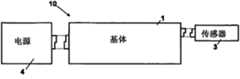
-图1示出根据该发明的传感和/或致动结点或终端装置的网络的结点元件的基础配置,其包含传感器的支持装置;- Figure 1 shows the basic configuration of the node elements of the network of sensing and/or actuating nodes or terminal devices according to the invention, which contains the supporting means of the sensors;
-图1A示出根据该发明的图1的传感和/或致动结点或终端装置的网络的结点元件的基体;- FIG. 1A shows the base body of the node elements of the network of sensing and/or actuating nodes or end devices of FIG. 1 according to the invention;
-图2示出基体中存在的必要组件的框图;- Figure 2 shows a block diagram of the necessary components present in the base body;
-图3示出应用于病人以便监视例如生理参数的结点元件的网络,全部元件具有图1的基础配置;- Figure 3 shows a network of nodal elements applied to a patient in order to monitor eg a physiological parameter, all elements having the basic configuration of Figure 1;
-图4和5和各自的放大局部图4B、4C和5A根据该发明示出适合连接传感器和/或致动器的强制啮合工具,并且图4A的放大图根据该发明示出用于连接另外的扩展馈电模块的硬件类型连接;- Figures 4 and 5 and their enlarged partial figures 4B, 4C and 5A show according to the invention a positive engagement tool suitable for connecting sensors and/or actuators, and the enlarged view of Figure 4A shows according to the invention for connecting another The hardware type connection of the expansion feed module;
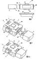
-图6示出终端装置的前视图,该终端装置包含侧面安装的支持装置、传感器和/或致动器以及应用于该终端装置较低部分的电池元件;- Figure 6 shows a front view of a terminal device comprising side mounted support means, sensors and/or actuators and battery elements applied to the lower part of the terminal device;
-图7示出图6的装置的分解透视图,然而其中供电电池不可见;- Figure 7 shows an exploded perspective view of the device of Figure 6, however in which the power supply battery is not visible;
-图7A示出图7的装置在装配配置中的透视图;- Figure 7A shows a perspective view of the device of Figure 7 in an assembled configuration;
-图8示出概略简化图,相对于图1的概略简化图,该图包含设置在传感器和基体之间的适配器元件或前端元件;- FIG. 8 shows a schematically simplified diagram, with respect to that of FIG. 1 , comprising an adapter element or a front element arranged between the sensor and the base body;
-图9示出图8的装置的前视图,其中示出供电电池;- Figure 9 shows a front view of the device of Figure 8, showing the power supply battery;
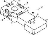
-图10示出图8和9的装置的透视分解图,其中不同的是供电电池没有示出;- Figure 10 shows a perspective exploded view of the device of Figures 8 and 9, with the difference that the power supply battery is not shown;
-图11示出图10的装置的装配图;- Figure 11 shows an assembled view of the device of Figure 10;
-图12示出集成的支持装置,其相对于图9中示出的装置具有进一步的扩展元件;- Figure 12 shows an integrated support device with further expansion elements relative to the device shown in Figure 9;
-图13示出在使用时位于基体和传感器和/或致动器之间的适配器或前端元件的必要组件的框图;- Figure 13 shows a block diagram of the necessary components of the adapter or front element located in use between the base body and the sensor and/or actuator;
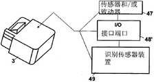
-图14和14A示出传感器和/或致动器内部结构部分的框图;- Figures 14 and 14A show block diagrams of internal structural parts of sensors and/or actuators;
-图15示出在使用时位于两个相应的基体之间的桥接口元件的必要组件的框图;- Figure 15 shows a block diagram of the necessary components of a bridging interface element located in use between two corresponding substrates;
-图16和16A分别示出根据该发明的两个相应基体之间的连接桥的装配图和分解图,而图16B示出根据该发明的层叠形式的连接桥;- Figures 16 and 16A show respectively an assembled and an exploded view of a connecting bridge between two corresponding substrates according to the invention, while Figure 16B shows a connecting bridge according to the invention in laminated form;
-图17示出通过图16的连接桥集成的两个基体的可能配置的框图;- Figure 17 shows a block diagram of a possible configuration of two substrates integrated via the connecting bridge of Figure 16;
-图18示出开启时基体的自配置步骤的框图;- Figure 18 shows a block diagram of the self-configuration steps of the substrate when switched on;
-图19示出基体怎样识别模块的连接的操作概略图;- Figure 19 shows an operational overview of how the base recognizes the connections of the modules;
-图20示出模拟型识别工具的示范实施例的电路图,该识别工具设置在基体和模块之间,该模块从以下元件构成的集合中选择:传感器和/或致动器、接口元件或桥连接元件;- Fig. 20 shows a circuit diagram of an exemplary embodiment of an identification means of the analog type, arranged between a base body and a module selected from the group consisting of: sensors and/or actuators, interface elements or bridges connecting elements;
-图21示出图19的示范实施例,该示范实施例扩展到其中模块的存在的连接的识别包括接口适配器元件或前端元件的情况,该接口适配器元件或前端元件设置在基体和传感器和/或致动器之间;- Fig. 21 shows the exemplary embodiment of Fig. 19 extended to the case where the identification of the existing connection of the module comprises an interface adapter element or a front element arranged between the base body and the sensor and/or or between actuators;
-图22示出描述模拟识别工具遵循的逻辑步骤序列的流程图;- Figure 22 shows a flowchart describing the logical sequence of steps followed by the simulation identification tool;
-图23示出数字识别工具遵循的逻辑步骤序列的相应流程图;- Figure 23 shows a corresponding flowchart of the sequence of logical steps followed by the digit recognition tool;
-图24示出图23的流程图的方框中一个的所谓握手过程的概略简化图;- Figure 24 shows a schematic simplified diagram of the so-called handshake process in one of the blocks of the flowchart of Figure 23;
-图25示出包括两个相应的基体之间的连接桥的进一步配置例子;- Figure 25 shows an example of a further configuration comprising a connecting bridge between two corresponding substrates;
-图26示出图25的图的方框中一个的所谓握手过程的概略简化图,该握手过程在连接桥的情况下实现;- Figure 26 shows a schematic simplified diagram of a so-called handshake process in one of the blocks of the diagram of Figure 25, which is implemented in the case of a connection bridge;
-图27示出在连接面上配备的支持装置,其中相应的传感器和/或致动器具有或没有接口元件;- Figure 27 shows the supporting means equipped on the connection surface, where the corresponding sensors and/or actuators have or do not have interface elements;
-图28和28A示出测量血压的传感器化的手镯,该手镯可固定到病人手腕,具体地,两张图示出与基体的连接;- Figures 28 and 28A show a sensorized bracelet for measuring blood pressure, which can be fixed to the patient's wrist, in particular, both figures show the connection to the base body;
-图29示出图28的手镯的测量病人“心跳”的可能应用;- Figure 29 shows a possible application of the bracelet of Figure 28 for measuring the "heartbeat" of a patient;
-图30示出基体和相对的电极传感器的支持带状物;- Figure 30 shows the substrate and the supporting strip of the opposite electrode sensor;
-图31示出图30的特定视图,其中示出到基体的连接;- Figure 31 shows a particular view of Figure 30 showing the connection to the base;
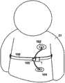
-图32示出图30的带状物的可能应用,其应用于病人的躯体用以阻抗检测。- Figure 32 shows a possible application of the ribbon of Figure 30, applied to the body of a patient for impedance detection.
具体实施方式Detailed ways
参考图1和1A,示出传感器和/或致动器的支持装置,在可能的实施例中,所述传感器和/或致动器作为传感器和/或致动器的无线网络20(在图3中可见)的结点元件或终端装置10。具体地,终端装置10的结构构造具有包含基体或基础模块1的独特特性,如图1A中详细示出,该基体或基础模块1具有多个面2,传感器和/或致动器区块/模块3和供电区块/模块4安装到所述多个面2。基体1的主要特性是通过添加如图中所示进一步的传感器和/或致动器3和其它供电模块4或扩展模块来集成结点元件10的可能性。Referring to Figures 1 and 1A, a support arrangement for sensors and/or actuators is shown, in a possible embodiment, as a
图1A示出优选平行六面体平坦形状的基体1,该基体1具有四个基本矩形的延长的连接面2,连接面2在每个矩形连接面2提供传感器和/或致动器3之间的强制啮合表面。FIG. 1A shows a
此外,提供辅助模块,例如设置在传感器和/或致动器3与基体1之间的适配器元件40或前端模块,并提供扩展模块50(在图12中可见),例如显示器、LED元件、存储器扩展等等,以及提供能够将两个基体1连接在一起的桥接口元件或桥模块60(在图15中可见)。Furthermore, auxiliary modules are provided, such as
此外,基体1在提供连接表面的任何面2包含强制啮合工具54,该强制啮合工具54适合接收相应的传感器和/或致动器3或适配器元件40或桥接口元件60。在优选示范实施例中,强制啮合工具54确保许多区块之间的机电连接,并且此外制作强制啮合工具54以便允许针对用户的直观且容易的可达性。下面是详细描述。Furthermore, the
另外,每个单独的传感器和/或致动器模块或区块3具有容易使用且简洁的外观,因此终端用户可无困难地装配它而获得具有要求的特性和功能性的最终装置。In addition, each individual sensor and/or actuator module or
此外,例如,可提供整个装置10的可能盖子,以便完全密封装置10,因此它可以仅在传感器和/或致动器模块3接触病人21的身体(图3中可见)。Furthermore, for example, a possible cover of the
参考图2,示出对于终端装置10的功能性和坚固性必需的,而且可以是基体1的部分的内部元件。具体地,这样的元件包含含有微处理器(未示出)的控制单元5,存储单元6,该存储单元6与控制单元5通信,并存储多个配置参数、固件、数据,并且这样的元件包含无线通信工具7,该无线通信工具7适合构成使微处理器与远程单元通信的无线传感器网络(在图3中示出)。Referring to FIG. 2 , internal elements necessary for the functionality and robustness of the
此外,提供接口端口表面2、11,其分别允许与传感器和/或致动器3或适配器元件40的连接工具54的强制啮合,但同样允许与具有扩展元件50(在图12中示出)的桥接口元件60和硬件连接11的连接工具54的强制啮合。Furthermore, an
参考无线传感器网络20,图3中示出的远程单元包含其它基体1,其它的基体1具有相应传感器和/或致动器3和相对供电区块4,以及适合与基体1交换信号的至少一个数据控制单元30。With reference to the
具体地,基体1提供固定工具(未示出),用于将它固定到支持表面,例如其生理参数被监视的病人21(在图3中可见),或在家庭自动化领域中固定到家用表面,以便测量温度、压力等等。In particular, the
图3示出在卫生保健或家庭自动化领域适合测量生理参数或其它参数的结点元件的网络20的例子。具体地,网络20包含基础配置中的多个装置10,所述装置10根据一个或更多病人21确定的监视点安置。Figure 3 shows an example of a
根据图1的概略图,然后每个终端装置10包含安装在基体上的供电区块4和至少一个传感器和/或致动器3,依靠传感器和/或致动器检测的对应参数,例如温度、压力、心跳、呼吸等等。压力检测的特定情况参考图28、28A和29描述。According to the schematic diagram of FIG. 1 , each
可配置基体1的可能方式允许获得结点元件,该结点元件非常灵活而且可实施到许多应用,尤其在监视生理参数领域。实际上,关于基体1的替换具有不同功能的传感器和/或致动器3或与其集成的特性,以及多个基体1互相连接的可能性允许发展宽领域的解决方案。The possible ways in which the
此外,每个基体1都用无线方式连接到同样可由病人21佩带的数据控制单元或BCU 30,作为便携装置30’。In addition, each
数据控制单元30可用无线方式同样连接到其它控制单元,例如便携装置30’,获得数据交换网络31。The data control
仅关于BCU 30,它可包含基体1的相同组件,并通常可具有有线或无线类型的连接36,从而连接到更强大的电子装置,例如个人数字助理33、移动电话32或个人计算机34,或通过连接37直接连接远程服务器35。通常,BCU 30可具有大于基体1的尺寸,以便容纳更强大的供电模块4,除非提供更传统的电缆供电。Concerning only the
根据网络20的每个单独基体1的操作,基体1与它物理连接的其它基体1或数据控制单元30通信可能的优先级指数,该可能的优先级指数对网络的每个单独结点元件必须传输的数据的相关性敏感。Depending on the operation of each
例如,在医疗领域,基体1可包含优先级高于具有温度传感器的基体的ECG传感器,该优先级可明显取决于监视的病状。For example, in the medical field, the
反之亦然,缺少通信模块表示基体1存在问题,或简单表示传感器和/或致动器3的移除。在此情况下,数据控制单元30被信号通知以从读取的数据的列表移除该基体1,直到同样由基体1可能发送信号通知状态改变,并且开始新的初始化步骤。Vice versa, the absence of a communication module indicates a problem with the
参考图4和5,根据透视图从上面和从下面分别示出基体1的视图。Referring to FIGS. 4 and 5 , views of the
参考图4A,示出硬件连接11,该硬件连接11适合将基础区块1与扩展区块50(在图12中示出)集成,或用于将基础区块1与另一基础区块1连接,如图16B中表示。具体地,该硬件连接11设置在基体1的顶面上,并且在扩展模块50(在图12中图解可见)或在另一基体1(在图5中可见)上具有对应端口14。这样,啮合部分11’和相应的协作部分14’(在图5中示出)不含糊地识别连接。此外,在基体1较低部分的端口14具有供电触点16,用于连接一个或更多供电区块4。Referring to FIG. 4A , there is shown a
图4B、4C和5A描绘在基体1的面2上安排的确定的连接区域的放大图,示出用来帮助模块的装配步骤,并且用于避免安装错误的强制啮合工具54。Figures 4B, 4C and 5A depict enlarged views of the defined connection areas arranged on the
具体地,强制啮合工具54提供在图4B中示出的凹口12,该凹口12与相应的紧固齿8(在图7中可见)啮合。这样,用户逐渐按压紧固齿8从而移除先前插入基体1的传感器和/或致动器3。该示范实施例也用于在传感器和/或致动器3’和前端40(在图10中可见)之间的连接,或在基体1和前端40之间连接,或用于将桥元件60与两个基体1(在图16中可见)连接。In particular, the
此外,强制啮合工具54提供凹槽12’,如放大图4C中所示,该凹槽12’使连接独特,并帮助用户安装传感器和/或致动器3。In addition, the
图5A示出另外的元件12”,该元件12”使传感器和/或致动器3或适配器元件40或桥模块60到基体1的连接独特。具体地,元件之间的区别是,在基体1的拐角,距对必须连接的模块的类型敏感的接口端口2的边缘依次产生不同距离。FIG. 5A shows a
更确切地,基体1可具有适合啮合某些传感器和/或致动器,而且然后啮合具有预定宽度的端口的类型,并且其它基体可具有适合啮合其它类型传感器和/或致动器,啮合具有不同宽度的接口的类型。因此,假设独特连接,前面的基体类型的传感器和/或致动器不能适配其它基体类型。Rather, the
强制啮合工具54可分别为模块/区块的供电、为自动识别并为数字和/或模拟类型的双向数据通信提供许多连接针脚。The positive engagement means 54 can provide a number of connection pins for the power supply of the modules/blocks, for automatic identification and for bi-directional data communication of digital and/or analog type, respectively.
同样,硬件输入端口11包含分别针对模块的供电的许多连接针脚,从而使优选同步串行类型的数字通信成为可能,并从而允许基体1自动识别连接的区块,以及从而通过专用通信协议实施数据的双向通信。Likewise, the
图6示出如图1中概略示出的装置的前视图,包含电池元件4和传感器和/或致动器3分别连接的基体1。FIG. 6 shows a front view of the device as schematically shown in FIG. 1 , comprising a
图7和7A分别描绘装置的分解和装配的对应透视图,没有示出供电模块4。在该配置中,传感器和/或致动器3具有配合存在于基体1的面2上的强制啮合工具54的啮合部分48。此外,传感器和/或致动器3具有紧固齿8。这样,连接对于用户非常容易且直观,因此连接不会错误发生,因为如果传感器和/或致动器3’连接适配器元件40,如图10所示,相应强制啮合工具54和啮合部分48不互相配合。7 and 7A depict respective exploded and assembled perspective views of the device, without the
图8示出配备适配器元件40或前端模块的终端装置10’的概略图。具体地,如图9和10的分解图所示,终端装置10’分别提供基体1、前端模块40、传感器和/或致动器3’以及供电区块4。Fig. 8 shows a schematic diagram of a terminal device 10' equipped with an
图9在前视图中示出在图8中概略示出的装置的示范实施例。具体地,由于借助相应供电触点针脚16’在基体1下施加供电区块4,因此供电区块4在这里可见,而在图10的透视图中,示出基体1、适配器元件40和传感器和/或致动器3’。在该示范实施例中,传感器和/或致动器3’具有可啮合前端模块40的插头啮合部分46的插座啮合部分48。FIG. 9 shows an exemplary embodiment of the device schematically shown in FIG. 8 in front view. In particular, the
这样,无经验的用户不能在不需要接口元件40的情况下将传感器和/或致动器3’错误地直接连接到基体1。In this way, an inexperienced user cannot mistakenly connect the sensor and/or actuator 3' directly to the
图11示出装配到单独的终端装置10’的上面描述的装置,终端装置10’是图3的监视网络20的结点元件的进一步配置。在图10和11中,没有示出供电区块4。Figure 11 shows the above-described device fitted to a single terminal device 10', which is a further configuration of the nodal element of the
图12描绘终端装置10”的前视图,除图9的部件之外,端装置10”包含通过硬件连接器11和对应端口14(在图5中详细可见)连接的扩展模块50。具体地,扩展模块50可从以下模块组成的集合中选择:显示器、计时器、计数器模块、串行通信模块、电池状态监视块、存储器扩展块等等。Figure 12 depicts a front view of an
图13示出可在传感器和/或致动器3’和基体1之间的强制啮合工具54处固定到基体1的适配器工具40或前端模块。Figure 13 shows an
在前端模块40中,至少必须存在下面的硬件组件:微控制器41、信号调整区块42、模/数和/或数/模转换器(ADC和/或DAC)43、前端元件的识别工具45、与基体1接合的输入/输出(I/O)接口端口44,以及与传感器和/或致动器模块3’接合的至少一个接口端口46或输入/输出啮合部分。In the front-
具体地,识别工具45从以下工具构成的集合中选择:能够测量物理量的模拟工具,或数字工具,例如用专用通信协议操作的数字工具。In particular, the identification means 45 are selected from the group consisting of: analog tools capable of measuring physical quantities, or digital tools, for example operating with a dedicated communication protocol.
这样,微控制器41能够驱动来自可能的传感器和/或致动器模块3’的信号,或指向可能的传感器和/或致动器模块3’的信号,该传感器和/或致动器模块3’连接适配器元件40。此外,微控制器41驱动模块识别部分和与基体1的通信。In this way, the
信号调整区块42适合调节来自连接前端40的可能的传感器和/或致动器模块3’的信号。这样的模块可包含例如放大器、多路复用器、开关、数字电位计电路器具等等。The
关于前端模块40的识别机构45,希望它在模块中,因此基体1不含糊地识别它通过接口端口44连接的任何适配器元件40。With regard to the
通过传感器和/或致动器3’的前端40执行相同过程,以识别它可连接哪个元件。The same process is carried out by the
图14和14A分别示出传感器和/或致动器模块3’与传感器和/或致动器模块3,具体地,它们包含传感器和/或致动器47、输入/输出接口端口48或48’,端口48或48’是分别将传感器和/或致动器模块3’和前端模块40连接,以及将传感器和/或致动器模块3和基体1直接连接的机电部分,并且与前面的情况相似,传感器和/或致动器模块3’和传感器和/或致动器模块3包含识别机构49,以便为传感器和/或致动器模块3’识别,以使模块可用独特方式识别在接口端口48连接的传感器和/或致动器3’的类型。具体地,取决于前端模块40是否必需,接口48和48’的连接端口表面相互不同。在使用中的结构区别在图7和10中示出。Figures 14 and 14A show respectively a sensor and/or actuator module 3' and a sensor and/or
图15示出桥接口元件或桥模块60的硬件组件,这些硬件组件是以下组件:微控制器81、桥模块的识别工具85和与两个基体1接合的输入/输出接口84的两个对应连接端口表面。如在图16和16A中可见,连接的进一步的可能性提供通过相应接口84分别连接两个基体1的桥接口元件60(在图15中可见)。这样,可能增加连接面2的数量,并因此增加可连接的传感器和/或致动器3的数量。此外,可能增加网络20的每个单独结点元件的能力和/或功能性。FIG. 15 shows the hardware components of the bridge interface element or
桥模块60和前端模块40之间的主要区别,一方面在于如图13和15描述的不同组件,并且另一方面在于它们的结构方面,因为在前端40相同侧上的相应部分13’,如图10所示,设置在桥接口60的相反侧,以便允许两个基体1的连接。可替换地,如图16B所示,两个基体1之间的连接可使用硬件连接11产生,具体地,将啮合到在基体1较低部分上制作的端口11到端口14组合(在图5中可见)。The main difference between the
图17示出在两个基体1之间通过桥元件60的可能的连接配置的框图。FIG. 17 shows a block diagram of a possible connection arrangement between two
具体地,每个终端装置10都通常由在框图中示出的以下模块组成:Specifically, each
-基础模块1;-
-可以具有或不具有用于调节信号的适配器元件40的传感器和/或致动器模块3或3’;- a sensor and/or
-调节信号的前端模块或适配器元件40;- a front-end module or
-供电模块4(在图中它称为电源);- power supply module 4 (in the figure it is called power supply);
-能够连接两个基体1的桥模块60;- a
-能够向基体1添加功能(存储器、显示器等等的扩展)的可能扩展模块50。- A
制作上面描述的区块之间的连接和机电连接器54(在图4和5中示出),以便为用户确保“即插即用”的直观过程和容易的可达性。The connections between the blocks described above and the electromechanical connectors 54 (shown in Figures 4 and 5) are made so as to ensure a "plug and play" intuitive process and easy accessibility for the user.
具体地,许多模块到基体1的连接通过首先连接至少一个供电模块4,并然后在没有特殊顺序的情况下连接其它模块实现。独特的连接通过允许在许多种连接的传感器和/或致动器中进行区分的键锁型机械接口(在图4和5中详细示出)来确保。在该连接,系统可由小型键开关开启,或在第一电池插入时自动开启。In particular, the connection of a number of modules to the
图18示出描述在开启后基体1遵循的逻辑步骤的流程图。Figure 18 shows a flow chart describing the logical steps followed by the
具体地,对存在于基体1中的微控制器5用确保终端用户非常容易的使用和整个系统的完全可配置性的代码(固件)编程,该整个系统既是单独结点10也是由许多单独结点组成的整个网络20(在图3中可见)。特殊地,提供无线网络中的单独基体1的自配置系统,其在前者开启时触发,并且提供连接到基体1的区块的自配置系统。In particular, the
程序的流程图,如图18中概略示出,提供以下步骤:The flowchart of the program, schematically shown in Figure 18, provides the following steps:
1.开启,即,连接第一电源模块4,或转换位于基体1上的开关;1. Turn on, that is, connect the
2.控制无线网络的存在,并可能连接它;2. Control the existence of a wireless network and possibly connect to it;
3.遵循以下描述的过程,控制其它连接到基体1的模块的存在;3. Follow the procedure described below to control the presence of other modules connected to the
4.将(网络和连接的模块的)状态传送到网络协调器;4. Transfer the state (of the network and connected modules) to the network coordinator;
5.等待源自协调器的命令;5. Waiting for commands from the coordinator;
6.如果接收命令,就执行命令;6. If the command is received, execute the command;
7.开始睡眠模式,即,低功耗模式,并在某个时间后返回到步骤25。7. Start sleep mode, ie low power consumption mode, and return to step 25 after some time.
连接到基体的模块的网络状态和配置状态的变化包括专用中断子例程,并且它从上面描述清单的点2或3触发程序的重启动。Changes in network state and configuration state of modules connected to the base include a dedicated interrupt subroutine, and it triggers a restart of the program from
在开启系统时,基体1在基体1识别连接的单独模块和它们的功能期间开始起动过程。When switching on the system, the
由于它只是定义在板上提供的控制器的基础参数,因此这样的起动过程可看作微处理器系统的标准。然后遵循一步骤,该步骤专用来起动基于确定的专用协议的无线电参数。Such a start-up procedure can be considered standard for microprocessor systems since it only defines the basic parameters of the controller provided on the board. A step is then followed which is dedicated to starting the radio parameters based on the determined protocol-specific.
无线网络上的数据更新步骤在起动步骤结束提供;在该阶段期间,网络20的每个单独基体1与其它基体1或数据控制单元30通信,告它连接的模块以及根据网络的每个单独结点都必须传输的数据类型的优先级的可能指数。The data update step on the wireless network is provided at the end of the start-up step; during this phase, each
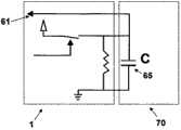
图19示出优选机构,根据该优选机构,基体1获知先验的未知类型的模块存在于接口的面2或11或14上的。该事件对应图22的示图的步骤26。具体地,部分64表示源自基体1边缘的两个连接针脚64’和64”,而部分63表示两个短路针脚63’和63”,该两个短路针脚存在于传感器和/或致动器模块3上,或存在于前端模块40上,或存在于桥模块60上,以通过端口2连接基体1,或存在于扩展模块50上以通过端口11或14连接基体1。更准确地,端口64是接口端口2、11和14的子系统,而63是接口44或48的连接端口表面的子系统,或是桥模块60的接口端口44的子系统,或是扩展模块50的接口端口14的子系统。连接70由底侧上的连接器的部分64限定,因为针脚64’通过另一侧上的连接器63短路接地。然后,根据需要模拟型连接识别70的模块和需要数字型连接识别70’的模块之间的区别,提供两个不同的识别过程。具体地,该区别通过电容器65的容量估计,或通过连接端口表面11或14而不是端口2估计。FIG. 19 shows a preferred mechanism according to which the
在连接端口表面2连接的全部模块执行第一模拟识别步骤,如图22和25描述的,该第一模拟识别步骤基于电容器65的容量的不同值。更复杂的模块,例如在图23和24中描述的需要数字识别机构的扩展模块50可仅在端口11或14连接,并且然后不需要电容器65,以便基体1的微处理器5(在图2中可见)获知要执行的模拟或数字识别过程。All modules connected at the
图23示出模块的模拟识别步骤70,因为该步骤70在连接成功时通过电容器65的由基础模块1的针脚激活的自动充电和自动放电的处理执行。在电容器65上的电压必需降低到低于某阈值时,通过基础模块1的输入针脚61检测和测量放电、处理。在属于同种连接70的两个不同模块之间区分的容量,通过安装在不同模块上时的电容器65的不同容量值实现。FIG. 23 shows the
图21示出存在于基础区块1中的微控制器5和存在于前端模块40中的微控制器41可怎样使用最小数量的电气连接,同时实现出现通过接口46和48的传感器和/或致动器3’和前端模块40之间的“连接状态”。一旦被识别,那么微控制器41驱动相似于图20中示出的过程,然而其中电容器65在此情况下处于连接前端模块40的传感器模块3’上,并且电容器65的充电和放电由存在于前端模块40中的微控制器41操作。一旦实现识别,那么微控制器41向微控制器5数字地通信传达连接的传感器和/或致动器3’的性质。在此情况下,通过经基体1的针脚64操作的电容器(未示出)的充电,基础模块1发信号通知前端模块40开始配置步骤,该配置步骤由在前端模块40上插入的微控制器41操作。一旦识别配置开始信号(电容器被充电),那么微控制器41进展到开始关于连接的传感器和/或致动器的相似充电和放电过程。FIG. 21 shows how the
缺少连接前端模块40的传感器和/或致动器3’表示错误状况,通过如图21中所示配置的合适数字线路向基体1发送信号告知该错误状况;该线路的状态改变向基体1发送信号告知已经解决错误状况。The absence of sensors and/or actuators 3' connected to the front-
图22示出许多传感器和/或致动器3与前端模块40的模拟识别过程采用的逻辑步骤的序列流程图,如上所述。Figure 22 shows a sequence flow diagram of the logical steps taken by the process of analog identification of a number of sensors and/or
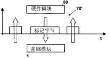
图23示出数字识别过程由扩展模块60的基体1操作,或由在所述基体1的连接端口表面11和/或14连接的其它基体1操作时采用的逻辑步骤的序列流程图。上面描述的流程图中图解的解决方案提供在单线上执行的所谓握手步骤,该单线专用于两个模块之间的数字识别。具体地,基体1激活针脚,该针脚配置为输出,连接到配置为“硬件”模块或扩展模块50的输入的针脚,在用识别连接的模块的类型的一位连续(a bit succession)响应之前,该“硬件”模块或扩展模块50将在其上已经接收信号的针脚转变为输出针脚。相似地,基体1在确定时间后将它的输出针脚转变为输入针脚,用于接收消息。针脚的接下来的转变允许基体1用进一步脉冲的确认正确收到消息。整个通信处理通过基体1生成的时钟信号同步,而且由标识符专用于在接口端口11或14上连接的模块50的针脚发送。FIG. 23 shows a sequence flow diagram of the logical steps employed when the digit recognition process is operated by the
图24概略图解上面描述的所谓握手步骤的数据流,如图23中表示的,该握手步骤识别与基体1的连接端口表面11或14啮合的扩展模块50或其它基体1。在此情况下,与前面情况相同,模拟识别是不充分的,因为它们是许多不同种类的装置,例如显示器、外部存储器、多种接口元件,等等,这些不同种类的装置可能需要复杂的通信协议,以便与基体1通信。FIG. 24 schematically illustrates the data flow of the above-described so-called handshaking step, which identifies the
参考图25,示出表示桥区块/模块60的识别步骤的流程图。Referring to FIG. 25 , a flowchart representing the identification steps of the bridge block/
图26详细示出所谓握手步骤期间的数字数据流,如图25的流程图中表示的。在此情况下,桥模块60通过同样在图16中示出的接口2的相应连接端口表面连接两个基体1。如图25中表示的,一旦桥区块60由它连接的两个基体1识别,那么握手过程开始,其中由桥区块60给予两个基体1作为主机72的功能,即,经无线电获得和传输全部数据,以及作为从机71的功能,即,通过桥60从主机72获得数据和向主机72传输数据。FIG. 26 details the flow of digital data during the so-called handshaking step, as represented in the flowchart of FIG. 25 . In this case, the
图27示出基体1,在全部连接面2上的相应传感器和/或致动器3’和3在具有或没有前端40帮助的情况下分别连接该基体1。该解决方案具有若干优点,例如用连接基体1的具有不同功能的其它模块替代传感器和/或致动器3的可能性,以及为医疗和/或家庭自动化领域中的任何监视和/或操作功能提供许多其它配置的可能性。Figure 27 shows the
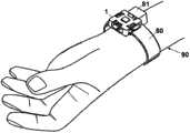
具体地,在医疗领域中,选择固定工具,例如可固定到病人的手腕90(图29)的手镯80(图28和28A),或可固定到病人21的躯干(图32)的带状物100(图30和31)。In particular, in the medical field, a fixation tool of choice, such as a bracelet 80 ( FIGS. 28 and 28A ) fixable to the patient's wrist 90 ( FIG. 29 ), or a belt fixable to the torso of the patient 21 ( FIG. 32 ) 100 (Figures 30 and 31).
两种类型的固定工具都用来监视/测量病人的生理参数。Both types of fixation tools are used to monitor/measure physiological parameters of the patient.
在图28和28A的例子中,手镯80具有适合检测病人的“心跳”,或更普遍地检测血压的传感器的功能。那么在结构上,手镯包含内部监视传感器84和连接部分81,基体1通过连接端口54中的一个连接连接部分81(图28A)。更准确地,用于与基体1连接的强制啮合连接部分81具有与基体1的连接端口54啮合的紧固齿8。In the example of Figures 28 and 28A, the
更详细地,传感器84包含检测平面84’(没有详细示出),该检测平面84’从连接部分81伸出,并且在使用中接触病人的桡动脉(radialartery)。这样,对传感器1和其它可能的传感器和/或致动器的基体1的应用容易且有效,并允许按要求修改装置。除模块化之外,进一步的优点是尺寸与已知装置相比更紧凑,以使病人可容易携带手镯甚至更长时间。In more detail, the
相似地,如图30所示,带状物100包含用于检测生理参数的传感器,并且与手镯80的情况相同,包含与基体1连接的连接部分105,如图31中详细示出,该连接部分105适合将传感器电气连接到基体。具体地,传感器是一对检测电极102和104,依靠相应线缆101和103有线连接到连接部分105,用于测量病人21的病人身体的阻抗,如在图32中可见的。Similarly, as shown in FIG. 30 , the
在可能的实施例中,带状物100和手镯80可以在长度上可调,并且与外壳(未示出)的相互耦合可在相应连接部分80和105上提供,该连接部分80和105如果存在,则除将带状物/手镯紧固到病人之外,还操作传感器。In a possible embodiment, the
在进一步的示范实施例中,手镯80和带状物100可由借助快速可释放紧固工具互相连接的两部分构成。这样,可调节它们以便容易且快速适合和病人21的手腕90或躯干,而不妨碍或阻碍病人的运动。In a further exemplary embodiment, the
根据概念上的观点,特殊实施例的前面的描述如此完全展现该发明,因此通过应用当前知识,其它人能够为各种应用修改这样的实施例和/或使这样的实施例适合各种应用,而无需进一步研究且不背离该发明,并且因此要理解的是,必须认为这样的调整与修改是特殊实施例的等效物。实现在此描述的不同功能的工具和材料可具有不同性质而不因为此原因背离该发明的领域。要理解的是在此采用的措辞或术语为描述目的而不是为了限制。The foregoing description of particular embodiments so fully reveals the invention from a conceptual point of view that, by applying current knowledge, others can modify and/or adapt such embodiments for various applications, without further study and without departing from the invention, and it is therefore to be understood that such adaptations and modifications must be considered equivalents of the particular embodiments. The means and materials to perform the different functions described herein may be of different nature without departing from the scope of the invention for this reason. It is to be understood that the phraseology or terminology employed herein is for the purpose of description and not limitation.
Claims (15)
Translated fromChineseApplications Claiming Priority (3)
| Application Number | Priority Date | Filing Date | Title |
|---|---|---|---|
| IT000032AITPI20080032A1 (en) | 2008-04-18 | 2008-04-18 | SUPPORT DEVICE FOR SENSORS AND / OR ACTUATORS MADE AS A NETWORK OF MEASUREMENT AND / OR IMPLEMENTATION KNOTS |
| ITPI2008A000032 | 2008-04-18 | ||
| PCT/IB2009/005264WO2009127954A2 (en) | 2008-04-18 | 2009-04-16 | Support device for sensors and/or actuators that can be part of a wireless network of sensors/actuators |
Publications (2)
| Publication Number | Publication Date |
|---|---|
| CN102006820Atrue CN102006820A (en) | 2011-04-06 |
| CN102006820B CN102006820B (en) | 2013-11-27 |
Family
ID=40297159
Family Applications (1)
| Application Number | Title | Priority Date | Filing Date |
|---|---|---|---|
| CN2009801132575AExpired - Fee RelatedCN102006820B (en) | 2008-04-18 | 2009-04-16 | Support device for sensors and/or actuators which may be part of a wireless network of sensors and/or actuators |
Country Status (15)
| Country | Link |
|---|---|
| US (1) | US9612140B2 (en) |
| EP (1) | EP2276395B1 (en) |
| JP (1) | JP5637517B2 (en) |
| KR (1) | KR101589232B1 (en) |
| CN (1) | CN102006820B (en) |
| BR (1) | BRPI0911797B8 (en) |
| CY (1) | CY1115737T1 (en) |
| DK (1) | DK2276395T3 (en) |
| ES (1) | ES2523493T3 (en) |
| HR (1) | HRP20141079T1 (en) |
| IT (1) | ITPI20080032A1 (en) |
| PL (1) | PL2276395T3 (en) |
| PT (1) | PT2276395E (en) |
| SI (1) | SI2276395T1 (en) |
| WO (1) | WO2009127954A2 (en) |
Cited By (10)
| Publication number | Priority date | Publication date | Assignee | Title |
|---|---|---|---|---|
| CN105323997A (en)* | 2014-05-27 | 2016-02-10 | 横河电机株式会社 | Receptacle for connecting modular electronic instruments |
| CN106170318A (en)* | 2014-02-17 | 2016-11-30 | 温麦迪科责任有限公司 | Equipment for measuring multiple parameters of patients undergoing radiopharmaceutical therapy |
| CN106458116A (en)* | 2014-06-18 | 2017-02-22 | 罗伯特·博世有限公司 | System for transmitting information to a subunit |
| CN106999066A (en)* | 2016-11-15 | 2017-08-01 | 深圳达闼科技控股有限公司 | Multifunctinoal health detection means |
| CN107106052A (en)* | 2014-12-30 | 2017-08-29 | 通用电气公司 | Universal display unit for a variety of wireless medical sensors |
| CN107198514A (en)* | 2017-04-24 | 2017-09-26 | 深圳恩启科技有限公司 | A kind of home medical device based on building blocks connecting method |
| CN107421587A (en)* | 2017-08-22 | 2017-12-01 | 山东东润仪表科技股份有限公司 | A kind of combined sensor |
| WO2019023055A1 (en)* | 2017-07-28 | 2019-01-31 | Lifelens Technologies, Llc | Physiologic monitoring kits |
| CN110520680A (en)* | 2017-02-22 | 2019-11-29 | 江森自控科技公司 | Integrated-type intelligent actuator devices |
| CN116149499A (en)* | 2023-04-18 | 2023-05-23 | 深圳雷柏科技股份有限公司 | Multi-mode switching control circuit and switching control method for mouse |
Families Citing this family (54)
| Publication number | Priority date | Publication date | Assignee | Title |
|---|---|---|---|---|
| US6850788B2 (en) | 2002-03-25 | 2005-02-01 | Masimo Corporation | Physiological measurement communications adapter |
| US9161696B2 (en)* | 2006-09-22 | 2015-10-20 | Masimo Corporation | Modular patient monitor |
| US8840549B2 (en) | 2006-09-22 | 2014-09-23 | Masimo Corporation | Modular patient monitor |
| US9153112B1 (en) | 2009-12-21 | 2015-10-06 | Masimo Corporation | Modular patient monitor |
| US20110178375A1 (en)* | 2010-01-19 | 2011-07-21 | Avery Dennison Corporation | Remote physiological monitoring |
| US20110208013A1 (en)* | 2010-02-24 | 2011-08-25 | Edwards Lifesciences Corporation | Body Parameter Sensor and Monitor Interface |
| US9339242B2 (en) | 2010-04-21 | 2016-05-17 | Pacific Place Enterprises, Llc | Systems, methods, components, and software for monitoring and notification of vital sign changes |
| US10603208B2 (en)* | 2011-01-21 | 2020-03-31 | Carewave Medical, Inc. | Modular stimulus applicator system and method |
| US8793522B2 (en)* | 2011-06-11 | 2014-07-29 | Aliphcom | Power management in a data-capable strapband |
| US9069380B2 (en) | 2011-06-10 | 2015-06-30 | Aliphcom | Media device, application, and content management using sensory input |
| US9271864B2 (en) | 2011-10-04 | 2016-03-01 | Feinstein Patents Llc | Orthosis for range of motion, muscular and neurologic rehabilitation of the lower extremities |
| WO2013056160A2 (en) | 2011-10-13 | 2013-04-18 | Masimo Corporation | Medical monitoring hub |
| US9943269B2 (en) | 2011-10-13 | 2018-04-17 | Masimo Corporation | System for displaying medical monitoring data |
| JP6214561B2 (en) | 2012-01-19 | 2017-10-18 | ボルケーノ コーポレイション | Interface device, system and method for use with an intravascular pressure monitoring device |
| US9186071B2 (en)* | 2012-01-27 | 2015-11-17 | Qualcomm Incorporated | Unlocking a body area network |
| US10149616B2 (en) | 2012-02-09 | 2018-12-11 | Masimo Corporation | Wireless patient monitoring device |
| US10307111B2 (en) | 2012-02-09 | 2019-06-04 | Masimo Corporation | Patient position detection system |
| US9749232B2 (en) | 2012-09-20 | 2017-08-29 | Masimo Corporation | Intelligent medical network edge router |
| JP2014112819A (en) | 2012-10-30 | 2014-06-19 | Yokogawa Electric Corp | Radio equipment, input/output unit, radio unit and radio equipment setup method |
| JP6393275B2 (en) | 2012-12-21 | 2018-09-19 | ボルケーノ コーポレイション | Wireless interface device, system, and method for use with an intravascular pressure monitoring device |
| JP6532857B2 (en) | 2013-03-15 | 2019-06-19 | ボルケーノ コーポレイション | Interface device, system and method for use with an intravascular pressure monitoring device |
| KR101456591B1 (en)* | 2013-03-26 | 2014-10-31 | 경북대학교 산학협력단 | Bio-signal measuring watch and method for measuring bio-signal |
| JP5898642B2 (en) | 2013-05-20 | 2016-04-06 | 横河電機株式会社 | Wireless equipment |
| FR3008602A1 (en)* | 2013-07-19 | 2015-01-23 | Lape Medical | PATCH MONITORING DEVICE |
| US10832818B2 (en) | 2013-10-11 | 2020-11-10 | Masimo Corporation | Alarm notification system |
| TWI651621B (en)* | 2013-12-18 | 2019-02-21 | 財團法人國家實驗研究院 | Sensing system with re-modularized sensing device and initialization method using the same |
| EP2901921A3 (en)* | 2014-02-01 | 2015-11-04 | Pacific Place Enterprises, LLC | Systems for monitoring and notification of vital sign changes |
| ES2732556T3 (en)* | 2014-02-12 | 2019-11-25 | Alcatel Lucent | Modular sensor system, method, sensor module and software product |
| FR3027387B1 (en)* | 2014-10-16 | 2018-02-16 | Senstronic | SENSOR DEVICE WITH MODULAR CONSTITUTION AND INDUSTRIAL EQUIPMENT COMPRISING SAME |
| KR101645443B1 (en)* | 2014-11-18 | 2016-08-04 | (주)프로차일드 | Sensor expansion type smart band and method |
| US9945701B2 (en)* | 2015-07-17 | 2018-04-17 | Fisher Controls International Llc | Actuator bracket having a sensor |
| KR102612874B1 (en) | 2015-08-31 | 2023-12-12 | 마시모 코오퍼레이션 | Wireless patient monitoring systems and methods |
| US9848280B2 (en)* | 2015-09-03 | 2017-12-19 | Civionics, Inc. | Wireless sensor module |
| US10463253B2 (en) | 2016-05-13 | 2019-11-05 | General Electric Company | Interface for two-part wearable patient monitoring device |
| US10617302B2 (en) | 2016-07-07 | 2020-04-14 | Masimo Corporation | Wearable pulse oximeter and respiration monitor |
| IT201600091313A1 (en)* | 2016-09-09 | 2018-03-09 | Medicaltech S R L | CONNECTOR FOR ELECTROMEDICAL EQUIPMENT |
| JP7197473B2 (en) | 2016-10-13 | 2022-12-27 | マシモ・コーポレイション | System and method for patient fall detection |
| EP3311735A1 (en)* | 2016-10-19 | 2018-04-25 | King's Metal Fiber Technologies Co., Ltd. | Flexible apparatus |
| KR101898589B1 (en)* | 2017-01-02 | 2018-09-13 | 엘지전자 주식회사 | Hub apparatus for network, Sub apparatus for motion and Comunication robot using the same |
| JP2021517024A (en) | 2018-03-07 | 2021-07-15 | ソーヴ ラボズ インコーポレイテッド | Systems and methods for improved pain relief from heat fiber stimulation |
| WO2021252732A1 (en)* | 2020-06-10 | 2021-12-16 | Northwestern University | Hydration sensor for monitoring and diagnosis of skin diseases in any environment and application of same |
| WO2019191703A1 (en)* | 2018-03-30 | 2019-10-03 | Northwestern University | Wireless skin sensor with methods and uses |
| WO2019204368A1 (en) | 2018-04-19 | 2019-10-24 | Masimo Corporation | Mobile patient alarm display |
| PT3654115T (en)* | 2018-05-16 | 2022-07-20 | Robot S A | Building automation device |
| US11272839B2 (en) | 2018-10-12 | 2022-03-15 | Ma Simo Corporation | System for transmission of sensor data using dual communication protocol |
| JP7350882B2 (en)* | 2019-04-30 | 2023-09-26 | ムラタ バイオス インコーポレイテッド | Patient-worn sensor containing flexible printed circuit assembly |
| US12390114B2 (en) | 2020-03-20 | 2025-08-19 | Masimo Corporation | Wearable device for monitoring health status |
| WO2021232150A1 (en)* | 2020-05-19 | 2021-11-25 | National Research Council Of Canada | A multi-channel and agnostic hardware-software interface and database architecture for predictive and prescriptive materials discovery |
| USD980091S1 (en) | 2020-07-27 | 2023-03-07 | Masimo Corporation | Wearable temperature measurement device |
| USD974193S1 (en) | 2020-07-27 | 2023-01-03 | Masimo Corporation | Wearable temperature measurement device |
| USD1072837S1 (en) | 2020-10-27 | 2025-04-29 | Masimo Corporation | Display screen or portion thereof with graphical user interface |
| USD1000975S1 (en) | 2021-09-22 | 2023-10-10 | Masimo Corporation | Wearable temperature measurement device |
| KR102482274B1 (en)* | 2022-04-28 | 2022-12-27 | 장석규 | Sensor assembly and modular unit using the same |
| USD1048908S1 (en) | 2022-10-04 | 2024-10-29 | Masimo Corporation | Wearable sensor |
Citations (4)
| Publication number | Priority date | Publication date | Assignee | Title |
|---|---|---|---|---|
| US20020084904A1 (en)* | 1996-12-20 | 2002-07-04 | Carlos De La Huerga | Electronic identification apparatus |
| US20050265269A1 (en)* | 2004-05-31 | 2005-12-01 | Yokogawa Electric Corporation | Signal transmission apparatus |
| US20060122466A1 (en)* | 2002-08-15 | 2006-06-08 | Trong-Nghia Nguyen-Dobinsky | Telemedicine system comprising a modular universal adapter |
| US20080081676A1 (en)* | 2006-09-29 | 2008-04-03 | Rosemount, Inc. | Power management system for a field device on a wireless network |
Family Cites Families (13)
| Publication number | Priority date | Publication date | Assignee | Title |
|---|---|---|---|---|
| US4141351A (en)* | 1977-09-12 | 1979-02-27 | Motorola, Inc. | ECG electrode impedance checking system as for emergency medical service |
| JP2000125442A (en)* | 1998-10-14 | 2000-04-28 | Akuton Technology Kk | Hub system of computer |
| US6678535B1 (en)* | 2000-06-30 | 2004-01-13 | International Business Machines Corporation | Pervasive dock and router with communication protocol converter |
| EP1303213A4 (en)* | 2000-07-18 | 2008-04-02 | Motorola Inc | Wireless electrocardiograph system and method |
| US20040127802A1 (en)* | 2001-07-17 | 2004-07-01 | Gmp Companies, Inc. | Wireless ECG system |
| US7509494B2 (en)* | 2002-03-01 | 2009-03-24 | Masimo Corporation | Interface cable |
| JP2004024551A (en)* | 2002-06-26 | 2004-01-29 | Renesas Technology Corp | Semiconductor device for sensor system |
| US20060009697A1 (en) | 2004-04-07 | 2006-01-12 | Triage Wireless, Inc. | Wireless, internet-based system for measuring vital signs from a plurality of patients in a hospital or medical clinic |
| CN100471445C (en)* | 2005-08-01 | 2009-03-25 | 周常安 | Patch type physiological monitoring device |
| JP2007296266A (en)* | 2006-05-08 | 2007-11-15 | Physio Trace Kk | Biosensor device |
| US20070282208A1 (en)* | 2006-06-06 | 2007-12-06 | Bob Jacobs | Mobile computing device with integrated medical devices |
| US8180425B2 (en)* | 2006-12-05 | 2012-05-15 | Tyco Healthcare Group Lp | ECG lead wire organizer and dispenser |
| US20080319327A1 (en)* | 2007-06-25 | 2008-12-25 | Triage Wireless, Inc. | Body-worn sensor featuring a low-power processor and multi-sensor array for measuring blood pressure |
- 2008
- 2008-04-18ITIT000032Apatent/ITPI20080032A1/enunknown
- 2009
- 2009-04-16ESES09733311.6Tpatent/ES2523493T3/enactiveActive
- 2009-04-16USUS12/921,275patent/US9612140B2/ennot_activeExpired - Fee Related
- 2009-04-16PLPL09733311Tpatent/PL2276395T3/enunknown
- 2009-04-16KRKR1020107023023Apatent/KR101589232B1/enactiveActive
- 2009-04-16CNCN2009801132575Apatent/CN102006820B/ennot_activeExpired - Fee Related
- 2009-04-16WOPCT/IB2009/005264patent/WO2009127954A2/enactiveApplication Filing
- 2009-04-16PTPT97333116Tpatent/PT2276395E/enunknown
- 2009-04-16JPJP2011504561Apatent/JP5637517B2/ennot_activeExpired - Fee Related
- 2009-04-16DKDK09733311.6Tpatent/DK2276395T3/enactive
- 2009-04-16HRHRP20141079ATpatent/HRP20141079T1/enunknown
- 2009-04-16BRBRPI0911797Apatent/BRPI0911797B8/ennot_activeIP Right Cessation
- 2009-04-16EPEP09733311.6Apatent/EP2276395B1/enactiveActive
- 2009-04-16SISI200931059Tpatent/SI2276395T1/enunknown
- 2014
- 2014-11-12CYCY20141100942Tpatent/CY1115737T1/enunknown
Patent Citations (4)
| Publication number | Priority date | Publication date | Assignee | Title |
|---|---|---|---|---|
| US20020084904A1 (en)* | 1996-12-20 | 2002-07-04 | Carlos De La Huerga | Electronic identification apparatus |
| US20060122466A1 (en)* | 2002-08-15 | 2006-06-08 | Trong-Nghia Nguyen-Dobinsky | Telemedicine system comprising a modular universal adapter |
| US20050265269A1 (en)* | 2004-05-31 | 2005-12-01 | Yokogawa Electric Corporation | Signal transmission apparatus |
| US20080081676A1 (en)* | 2006-09-29 | 2008-04-03 | Rosemount, Inc. | Power management system for a field device on a wireless network |
Cited By (15)
| Publication number | Priority date | Publication date | Assignee | Title |
|---|---|---|---|---|
| CN106170318A (en)* | 2014-02-17 | 2016-11-30 | 温麦迪科责任有限公司 | Equipment for measuring multiple parameters of patients undergoing radiopharmaceutical therapy |
| CN105323997A (en)* | 2014-05-27 | 2016-02-10 | 横河电机株式会社 | Receptacle for connecting modular electronic instruments |
| CN105323997B (en)* | 2014-05-27 | 2019-07-12 | 横河电机株式会社 | Socket for link block electronic instrument |
| CN106458116B (en)* | 2014-06-18 | 2019-04-23 | 罗伯特·博世有限公司 | System for passing information to subunits |
| CN106458116A (en)* | 2014-06-18 | 2017-02-22 | 罗伯特·博世有限公司 | System for transmitting information to a subunit |
| CN107106052A (en)* | 2014-12-30 | 2017-08-29 | 通用电气公司 | Universal display unit for a variety of wireless medical sensors |
| CN106999066A (en)* | 2016-11-15 | 2017-08-01 | 深圳达闼科技控股有限公司 | Multifunctinoal health detection means |
| CN106999066B (en)* | 2016-11-15 | 2021-03-26 | 深圳达闼科技控股有限公司 | Multifunctional health detection device |
| CN110520680A (en)* | 2017-02-22 | 2019-11-29 | 江森自控科技公司 | Integrated-type intelligent actuator devices |
| US11042171B2 (en) | 2017-02-22 | 2021-06-22 | Johnson Controls Technology Company | Integrated smart actuator device |
| CN107198514A (en)* | 2017-04-24 | 2017-09-26 | 深圳恩启科技有限公司 | A kind of home medical device based on building blocks connecting method |
| WO2019023055A1 (en)* | 2017-07-28 | 2019-01-31 | Lifelens Technologies, Llc | Physiologic monitoring kits |
| CN107421587A (en)* | 2017-08-22 | 2017-12-01 | 山东东润仪表科技股份有限公司 | A kind of combined sensor |
| CN116149499A (en)* | 2023-04-18 | 2023-05-23 | 深圳雷柏科技股份有限公司 | Multi-mode switching control circuit and switching control method for mouse |
| CN116149499B (en)* | 2023-04-18 | 2023-08-11 | 深圳雷柏科技股份有限公司 | Multi-mode switching control circuit and switching control method for mouse |
Also Published As
| Publication number | Publication date |
|---|---|
| DK2276395T3 (en) | 2014-11-17 |
| ES2523493T3 (en) | 2014-11-26 |
| BRPI0911797B8 (en) | 2021-06-22 |
| KR101589232B1 (en) | 2016-01-27 |
| US9612140B2 (en) | 2017-04-04 |
| JP5637517B2 (en) | 2014-12-10 |
| BRPI0911797B1 (en) | 2020-09-15 |
| JP2011519588A (en) | 2011-07-14 |
| CN102006820B (en) | 2013-11-27 |
| EP2276395B1 (en) | 2014-08-13 |
| ITPI20080032A1 (en) | 2009-10-19 |
| PL2276395T3 (en) | 2015-03-31 |
| PT2276395E (en) | 2014-11-11 |
| WO2009127954A2 (en) | 2009-10-22 |
| BRPI0911797A2 (en) | 2015-10-06 |
| KR20100139024A (en) | 2010-12-31 |
| US20110021930A1 (en) | 2011-01-27 |
| SI2276395T1 (en) | 2015-01-30 |
| HRP20141079T1 (en) | 2015-01-30 |
| EP2276395A2 (en) | 2011-01-26 |
| CY1115737T1 (en) | 2017-01-25 |
| WO2009127954A3 (en) | 2010-03-25 |
Similar Documents
| Publication | Publication Date | Title |
|---|---|---|
| CN102006820B (en) | Support device for sensors and/or actuators which may be part of a wireless network of sensors and/or actuators | |
| US6524240B1 (en) | Docking station for portable medical devices | |
| US11031130B2 (en) | Patient support apparatus having data collection and communication capability | |
| US8262995B2 (en) | System with a pluggable data transfer module which transfers data from an analytical system to a data processing unit | |
| US9486138B2 (en) | Portable handheld medical diagnostic device having a mezzanine circuit board with a universal connection interface | |
| EP1815371B1 (en) | Method for automatic association of medical devices to a patient and concurrent creation of a patient record | |
| JP2009031264A (en) | Multi-configuration electronic thermometer | |
| US20060122466A1 (en) | Telemedicine system comprising a modular universal adapter | |
| CN108366740B (en) | Portable composite sensor device for measuring multiple biological information and measuring method | |
| WO2004104964A1 (en) | Device for transmitting data via the internet | |
| JP2004536636A (en) | Interface for portable point-of-care patient diagnostic equipment | |
| CN219250149U (en) | Monitoring processing device, bedside monitoring equipment, acquisition device and central monitoring system | |
| KR101466690B1 (en) | Glucosuria Data Gathering Module attachable to Mobile Device and Glucosuria Data Gathering Method thereof | |
| JP7050213B2 (en) | Biosensors, biosensor systems and motion control methods for biosensors | |
| TW201140364A (en) | Electronic health record storage device, system, and method | |
| CN205584189U (en) | A comprehensive equipment for connecting a plurality of portable autodiagnosis instruments | |
| CN209996312U (en) | Blood pressure measuring device | |
| JP4453866B2 (en) | Transmission system | |
| LINBO et al. | AN INQUIRY INTO THE DESIGN AND DEVELOPMENT OF VERY COST-EFFECTIVE ELECTRONIC COMPONENTS FOR HUMAN WAVE MONITORING SYSTEMS | |
| KR20050042964A (en) | Apparatus and system for complex somatometry | |
| CN117980854A (en) | Data storage from sensor arrays | |
| CN114206203A (en) | Patient monitoring method, equipment and central monitoring system | |
| JP2004080085A (en) | Control apparatus | |
| Shahin | Wireless communication and RFID based handheld database and medical diagnostic system | |
| TW201740342A (en) | Medical test system and medical test device setting with detachable streaming module thereof |
Legal Events
| Date | Code | Title | Description |
|---|---|---|---|
| C06 | Publication | ||
| PB01 | Publication | ||
| C10 | Entry into substantive examination | ||
| SE01 | Entry into force of request for substantive examination | ||
| C53 | Correction of patent of invention or patent application | ||
| CB02 | Change of applicant information | Address after:Italy pizza Applicant after:WINMEDICAL S.R.L. Address before:Italy pizza Applicant before:W.I.N.-WIRELESS INTEGRATED NETWORK S.R.L. | |
| COR | Change of bibliographic data | Free format text:CORRECT: APPLICANT; FROM: W. I. N. WIRELESS INTEGRATED NETWORK S. R. L. TO: WENMAIDIKE CO., LTD. | |
| C14 | Grant of patent or utility model | ||
| GR01 | Patent grant | ||
| CP01 | Change in the name or title of a patent holder | Address after:Italy pizza Patentee after:Wireless Integrated Network Co. Address before:Italy pizza Patentee before:WINMEDICAL S.R.L. | |
| CP01 | Change in the name or title of a patent holder | ||
| TR01 | Transfer of patent right | Effective date of registration:20181224 Address after:Italy pizza Patentee after:Winmedico Co. Address before:Italy pizza Patentee before:Wireless Integrated Network Co. | |
| TR01 | Transfer of patent right | ||
| TR01 | Transfer of patent right | Effective date of registration:20210305 Address after:Milan Italy Patentee after:AB MEDICA S.P.A. Address before:Italy pizza Patentee before:Winmedico Co. | |
| TR01 | Transfer of patent right | ||
| CF01 | Termination of patent right due to non-payment of annual fee | ||
| CF01 | Termination of patent right due to non-payment of annual fee | Granted publication date:20131127 |