CN102004407A - Image forming apparatus - Google Patents
Image forming apparatusDownload PDFInfo
- Publication number
- CN102004407A CN102004407ACN2010102639914ACN201010263991ACN102004407ACN 102004407 ACN102004407 ACN 102004407ACN 2010102639914 ACN2010102639914 ACN 2010102639914ACN 201010263991 ACN201010263991 ACN 201010263991ACN 102004407 ACN102004407 ACN 102004407A
- Authority
- CN
- China
- Prior art keywords
- post
- light source
- processing device
- image forming
- light
- Prior art date
- Legal status (The legal status is an assumption and is not a legal conclusion. Google has not performed a legal analysis and makes no representation as to the accuracy of the status listed.)
- Granted
Links
Images


Classifications
- G—PHYSICS
- G03—PHOTOGRAPHY; CINEMATOGRAPHY; ANALOGOUS TECHNIQUES USING WAVES OTHER THAN OPTICAL WAVES; ELECTROGRAPHY; HOLOGRAPHY
- G03G—ELECTROGRAPHY; ELECTROPHOTOGRAPHY; MAGNETOGRAPHY
- G03G15/00—Apparatus for electrographic processes using a charge pattern
- G03G15/65—Apparatus which relate to the handling of copy material
- G03G15/6552—Means for discharging uncollated sheet copy material, e.g. discharging rollers, exit trays
Landscapes
- Physics & Mathematics (AREA)
- General Physics & Mathematics (AREA)
- Folding Of Thin Sheet-Like Materials, Special Discharging Devices, And Others (AREA)
- Electrophotography Configuration And Component (AREA)
- Control Or Security For Electrophotography (AREA)
- Pile Receivers (AREA)
Abstract
Description
Translated fromChinese技术领域technical field
本发明涉及一种成像设备,该成像设备包括后处理装置,该后处理装置被设置为在体内纸张排出部处能够在其缩回位置和突出位置之间自由地移位,该体内纸张排出部分别被图像读取部和图像形成部夹在上侧和下侧之间。The present invention relates to an image forming apparatus comprising a post-processing device arranged to be freely displaceable between its retracted position and a protruded position at an internal paper discharge portion, the internal paper discharge portion It is sandwiched between the upper side and the lower side by the image reading section and the image forming section, respectively.
背景技术Background technique
近几年,随着对小型化的成像设备的需求的增长,已经使用了所谓的体内纸张排出型的成像设备,其中已经经过成像处理的记录介质被排出到纸张排出部,该纸张排出部被设置在本体内部且分别被图像读取部和图像形成部夹在上侧和下侧之间。在这样的体内纸张排出型的成像设备之中,其包括在体内纸张排出部处的后处理装置并将后处理(例如装订处理和/或打孔处理)应用到已经经过成像处理的记录介质上。In recent years, as the demand for miniaturized image forming apparatuses has increased, image forming apparatuses of a so-called internal paper discharge type have been used in which recording media that have undergone image processing are discharged to a paper discharge portion that is It is provided inside the main body and sandwiched between the upper side and the lower side by the image reading part and the image forming part, respectively. In such an image forming apparatus of the internal paper discharge type, it includes a post-processing device at the internal paper discharge portion and applies post-processing (such as stapling processing and/or punching processing) to a recording medium that has undergone image forming processing .
因为体内纸张排出部的顶面和下表面被图像读取部和图像形成部包围且其侧面中的一部分也被支撑图像读取部和图像形成部的支撑构件包围,因此体内纸张排出部与外部相比较昏暗。由此,存在与处理任务相关的问题,该任务例如为取回在体内纸张排出部处的记录介质,和/或对后处理装置的维护任务等。Since the top surface and the lower surface of the internal paper discharge part are surrounded by the image reading part and the image forming part, and a part of its sides are also surrounded by the support member that supports the image reading part and the image forming part, the internal paper discharge part is separated from the outside. Relatively dim. Thereby, there are problems associated with handling tasks such as retrieval of the recording medium at the in-body paper discharge, and/or maintenance tasks on post-processing devices, and the like.
所以,例如在日本未审专利公开No.1-294155中所描述的那样,已经提出了一种包括光源的成像设备,所述光源用于照亮被排出到体内纸张排出部的记录介质。Therefore, for example, as described in Japanese Unexamined Patent Publication No. 1-294155, there has been proposed an image forming apparatus including a light source for illuminating a recording medium discharged to a paper discharge portion inside the body.
然而,如在该专利文献中所提到的,在传统的成像设备中,由于光源被设置在体内纸张排出部的里部,使得从那里发射的直射光照亮体内纸张排出部的较宽范围,因此对于用户来说很可能看到来自光源的直射光。这种直射光可能使用户眼花,且然后很可能妨碍用户的工作能力。However, as mentioned in this patent document, in the conventional image forming apparatus, since the light source is provided inside the paper discharge part in the body, direct light emitted therefrom illuminates a wide range of the paper discharge part in the body , so it is likely for the user to see direct light from the light source. Such direct light may dazzle the user, and then likely impede the user's ability to work.
发明内容Contents of the invention
本发明致力于提供一种成像设备,所述成像设备能够在体内纸张排出部处通过用光源照亮体内纸张排出部而提供改进的可操作性,同时防止光源的直射光进入用户的视域内。The present invention seeks to provide an image forming apparatus capable of providing improved operability at an internal paper discharge portion by illuminating the internal paper discharge portion with a light source while preventing direct light of the light source from entering the user's field of vision.
成像设备包括主体、后处理装置、对象作业部、光源和遮光构件。主体包括体内纸张排出部,所述体内纸张排出部被设置在分别被图像读取部和图像形成部在上侧和下侧之间所夹的空间中,所述图像读取部用于读取文档的图像并产生一组图像数据,所述图像形成部用于基于该组图像数据对记录介质执行成像处理;且已经经过成像处理的记录介质被排出到体内纸张排出部。后处理装置被设置为能够在缩回位置和突出位置之间自由地移位,在所述缩回位置处后处理装置被接纳到体内纸张排出部内,在所述突出位置处后处理装置被拉向一个侧面侧;且在缩回位置处后处理装置对已经经过成像处理的记录介质实施处理。对象作业部沿后处理装置的拉出方向被设置于后处理装置的上游侧面;且对象作业部在突出位置中接受维护任务。光源被设置于后处理装置的上游侧面,并在突出位置处执行照亮对象作业部的功能。遮光构件被设置于后处理装置的上游侧面且位于光源的前面侧,并且阻挡光源的到达前面侧的直射光。An imaging device includes a main body, a post-processing device, an object handling section, a light source, and a light shielding member. The main body includes an internal paper discharge part provided in a space sandwiched between an upper side and a lower side by an image reading part and an image forming part respectively, the image reading part for reading An image of a document is generated and a set of image data is generated, and the image forming section performs imaging processing on a recording medium based on the set of image data; and the recording medium that has undergone the imaging processing is discharged to an internal paper discharge section. The post-processing device is configured to be freely displaceable between a retracted position, where the post-processing device is received into the internal paper discharge portion, and a protruding position, where the post-processing device is pulled to one side; and at the retracted position, the post-processing device performs processing on the recording medium that has undergone imaging processing. The target working part is provided on the upstream side of the post-processing device in the pull-out direction of the post-processing device; and the target working part accepts maintenance tasks in a protruding position. The light source is provided on the upstream side of the post-processing device, and performs a function of illuminating the subject working part at a protruding position. The light shielding member is provided on the upstream side of the post-processing device and on the front side of the light source, and blocks direct light from the light source reaching the front side.
因为对象作业部是在体内纸张排出部中被光源照亮,所以增加了对象作业部的亮度,提高了可见度,从而提高了对于对象作业部的可操作性。另一方面,因为遮光构件被设置于光源的前面侧,所以阻挡了光源的到达前面侧的直射光。Since the target working part is illuminated by the light source in the internal paper discharge part, the brightness of the target working part is increased, and the visibility is improved, thereby improving the operability for the target working part. On the other hand, since the light shielding member is provided on the front side of the light source, direct light from the light source reaching the front side is blocked.
附图说明Description of drawings
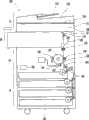
图1是根据本发明的实施例的成像设备的示意性前剖视图。FIG. 1 is a schematic front sectional view of an image forming apparatus according to an embodiment of the present invention.
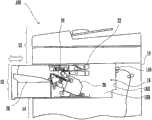
图2是后处理装置的示意性前剖视图。Fig. 2 is a schematic front sectional view of the aftertreatment device.
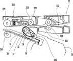
图3是示出纸张输送部、处理托盘、后处理部和堆叠托盘的前剖视图。3 is a front sectional view showing a sheet conveying section, a processing tray, a post-processing section, and a stacking tray.
图4是处理托盘的透视图。Figure 4 is a perspective view of a processing tray.
图5是后处理装置的透视图。FIG. 5 is a perspective view of an aftertreatment device.
图6是后处理装置的另一透视图。6 is another perspective view of the aftertreatment device.
图7是示出了光源和遮光构件的透视图。Fig. 7 is a perspective view showing a light source and a light shielding member.
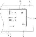
图8是示出了成像设备的轮廓构造的平面剖视图。FIG. 8 is a plan sectional view showing the outline configuration of the imaging device.
图9是示出了根据另一实施例的成像设备的轮廓构造的平面剖视图。FIG. 9 is a plan sectional view showing an outline configuration of an imaging apparatus according to another embodiment.
具体实施方式Detailed ways
下面基于附图说明本发明的实施例。Embodiments of the present invention will be described below based on the drawings.
如图1所示,成像设备100包括:主体19,所述主体19包括图像读取部12、图像形成部14和纸张供应部18,所述图像读取部12用于读取文档的图像并产生一组图像数据,所述图像形成部14用于在纸张上执行成像处理,所述纸张供应部18用于向图像形成部14顺序地供应纸张;和后处理装置20,所述后处理装置20用于在作为记录介质的例子的纸张上执行后处理,所述记录介质已经在图像形成部14处被实施了成像处理。成像设备100主要由控制部190控制。As shown in FIG. 1, the
体内纸张排出部16被设置于分别被图像读取部12和图像形成部14在上侧和下侧之间所夹的空间中。The internal
图像读取部12包括光学系统单元128和自动文档输送单元124,所述光学系统单元128被构造成读取在文档台126上的文档的图像,所述自动文档输送单元124用于将在文档承载台122上的文档顺序地输送到文档台126的文档读取位置。The
图像形成部14被设置在图像读取部12的下方。图像形成部14包括作为图像携载体的光导鼓142,该光导鼓142设置为邻接纸张输送路径186。在光导鼓142的周围设置静电充电装置143、曝光装置144、显影装置146、转印装置148和清洁单元150。静电充电装置143使光导鼓142均匀地充电到预定的静电电压。曝光装置144通过使光导鼓142曝光而在光导鼓142上形成静电潜像。显影装置146通过将显影剂供应到光导鼓142上使在光导鼓142上的静电潜像显影成显影剂图像。转印装置148将在光导鼓142上的显影剂图像转印到纸张上。清洁单元150收集残留在光导鼓142上的显影剂等。The
图像形成部14还包括定影装置152,所述定影装置152在纸张输送路径186中安装在光导鼓142的下游侧。定影装置152通过热和压力将已经转印到纸张上的显影剂图像固定到纸张上。在纸张输送路径186中的定影装置152的下游侧安装有引导辊154,所述引导辊154将已经经历成像处理的纸张引导到后处理装置20内。引导辊154被设置在体内纸张排出部16的右侧面16A上。The
纸张供应部18包括用于接纳纸张的多个纸张容纳盒182。每个纸张容纳盒182均安装有用于将纸张一张一张地送出到纸张输送路径186的送出机构。纸张供应部18还包括用于调整向图像形成部14供应纸张的时间的一对对准辊184。The
如图2所示,体内纸张排出部16在其顶面和下表面处分别被图像读取部12和图像形成部14包围,且在其后面16B和右侧面16A处被图像形成部14的一部分包围。也就是说,体内纸张排出部16仅在主体19的前面侧和左侧面侧是敞开的。As shown in FIG. 2 , the internal
后处理装置20被构造成能够在缩回位置和突出位置之间自由地移位,在所述缩回位置处其被接纳到体内纸张排出部16内,在所述突出位置处其相对于主体19被拉向左侧面侧。图1和图2中描述的是后处理装置20被从主体19中拉出的状态。在缩回位置处的后处理装置20在已经经过成像处理的纸张上执行后处理。The
后处理装置20包括纸张输送部22、处理托盘25、后处理部26和堆叠托盘28。纸张输送部22将已经通过引导辊154引入到后处理装置20中的纸张引导到处理托盘24中。当在后处理装置20被设置在缩回位置处的状态时,纸张输送部22被结合到纸张输送路径186。处理托盘24被构造成临时容纳将由后处理部26处理的一叠纸张。后处理部26被构造成在被放置到处理托盘24上的纸张上执行装订处理例如订书钉处理和/或打孔处理。堆叠托盘28被构造成容纳在已经由后处理部26后处理过之后排出的纸张。The
如图3所示,输送路径222被形成在纸张输送部22内使得将已经被从图像形成部14发送的纸张输送到水平方向。沿着输送路径222设置有一对输送辊224和另一对输送辊34。在输送路径222中的输送辊224的下游侧安装有传感器226,所述传感器226被构造成检测正被输送的纸张的引导边和尾端。输送辊34被构造成将待后处理的纸张排出到处理托盘24上。As shown in FIG. 3 , a
在输送路径222中的输送辊34的下游侧安装有纸张排出辊229和另一纸张排出辊244。纸张排出辊229被能绕轴旋转地支撑在纸张排出机构225的端部处,所述纸张排出机构225被以这样的方式支撑使得能够绕驱动辊228的辊轴227摆动。A
能够绕输送辊34的旋转轴38摆动的支撑臂32被连接到输送辊34上。滑轮30被能绕轴旋转地支撑在支撑臂32的一端处。履带31横跨过支撑臂32和滑轮30。履带31将在处理托盘24上的纸张引导到预定的对齐位置。确切地说,履带31被构造成向纸张传动输送力,直到引入到处理托盘24中的纸张的边缘与定位构件242形成接触。定位构件242被构造成在对齐位置处紧靠纸张的引导边缘。A
处理托盘24被构造成向上朝着排出方向倾斜。已经被引入到处理托盘24上的纸张由其自身的重量和履带31的输送力引导到处理托盘24的底边侧。用于将纸张输送到处理托盘24上的方法不限于此;所以,它可能包括另外的输送辊,该另外的输送辊被以此种方式构造使得与履带31协作以将纸张引导到对齐位置。The
如图4所示,以在处理托盘24的宽度方向上(垂直于纸张排出方向的方向)可移动的方式支撑的第一对齐板245和第二对齐板246被安装到处理托盘24上。通过安装在处理托盘24内部的齿条齿轮传动机构以及具有用于向齿轮传动装置供应驱动力的马达的第一激励器,第一对齐板245和第二对齐板246被构造成沿处理托盘24的宽度方向移动。然而,用于驱动第一对齐板245和第二对齐板246的方法不限于在该实施例中所描述的方法。因此,尽管在该实施例中后处理部26被构造成能沿处理托盘24的宽度方向移动,但是在实现本发明时沿处理托盘24的宽度方向移动后处理部26不是必须的要求,而是可选的要求。As shown in FIG. 4 , a
如图5和图6所示,后处理装置20被构造成能沿在体内纸张排出部16的下表面处安装的导轨161在缩回位置和突出位置之间移位。此外,被构造成能够在关闭位置和打开位置之间自由地摆动的开闭构件162被安装到体内纸张排出部16,在关闭位置处后处理装置20的前面41被覆盖,在打开位置处前面41被打开。开闭构件162通过体内纸张排出部16的下表面的前面的边缘部绕轴以可旋转方式支撑。此外,图5示出了开闭构件162处于关闭位置的状态,而图6示出了开闭构件162被移除时的另一状态。As shown in FIGS. 5 and 6 , the
后处理装置20包括在前面41上的锁定杆42。转动锁定杆42导致锁定或解除后处理装置20在缩回位置和突出位置之间的移置。
后处理装置20包括位于拉出方向的上游侧面上、即在右侧面44上的订书钉盒43。订书钉盒43容纳待供应到后处理部26的订书钉。订书钉盒43被配置成能附接到后处理装置20的右侧面44且能从后处理装置20的右侧面44分离。订书钉盒43是对象作业部,定期或不定期地对该对象作业部执行例如重装填订书钉等的维护任务。The
为了使纸张输送部22在缩回位置处被连接到纸张输送路径186,后处理装置20的右侧面44邻近于主体19。另一方面,当执行维护任务时,后处理装置20被拉出到突出位置以便在右侧面44和主体19之间形成空间。In order for the
如图5-图8所示,后处理装置20包括位于右侧面44且位于订书钉盒43的前面41侧的光源45。例如,使用白光LED(发光二极管)作为光源45。光源45具有在突出位置处照亮订书钉盒43的功能。光源45可以例如用半透明盖构件覆盖。As shown in FIGS. 5-8 , the
后处理装置20还包括位于右侧面44且位于光源45的前面41侧的遮光构件46。The
遮光构件46在高度上的尺寸被构造成比光源45在高度上的尺寸大。在高度方向上,光源45被设置在遮光构件46的上端和下端之间。在高度方向上,优选的是,光源45被设置在遮光构件46的中心处。遮光构件46在右侧面44上比光源45突出更多。遮光构件46阻挡光源45的到达前面41侧的直射光。The
当执行维护任务时,为了能够使后处理装置20被拉出到突出位置,转动锁定杆42使得后处理装置20的锁定被解除,并因此光源45被点亮。因此当后处理装置20被拉出到突出位置时,订书钉盒43被在体内纸张排出部16的后处理装置20和主体19之间的光源45照亮。When performing maintenance tasks, in order to enable the
因此,在订书钉盒43周围的亮度增加了,且因而提高了在订书钉盒43处的可操作性。另一方面,因为遮光构件46被设置在光源45的前面41侧中,所以阻挡了光源45的到达前面41侧的直射光。因此,当体内纸张排出部16被用光源45照亮时,提高了在体内纸张排出部16中的可见度,从而提高了可操作性,且防止了光源45的直射光进入到用户的视域中。由于直射光不会进入到用户的视域中,所以用户不会眼花,且因此消除了对可操作性的妨碍。Therefore, the brightness around the
另外,通过使用发光二极管(LED)作为光源45,能够以低功率来照亮体内纸张排出部16。此外,通过使用白光LED作为光源45,提高了用户在体内纸张排出部16中的可见度,且从而进一步提高了可操作性。此外,通过安装覆盖光源45的半透明盖构件,能够进一步缓和从光源45发射的光。In addition, by using a light emitting diode (LED) as the
仍进一步的,当作为用光源45照亮的对象的对象作业部是订书钉盒43时,与当纸张被照亮时相比,需要用光源45照亮的区域可更窄。Still further, when the subject work unit that is the subject of illumination with the
因此,能够降低光源45的光量,然后通过遮光构件46更可靠地阻挡到达前面41侧的直射光。Therefore, the light quantity of the
如图8所示,成像设备100包括在体内纸张排出部16的内面的至少一部分中的用于反射从光源45发射的光的反射构件163、164。在该实施例中,成像设备100包括设置在体内纸张排出部16的后面16B上的反射构件163和设置在体内纸张排出部16的右侧面16A上的反射构件164。因为体内纸张排出部16由于从反射构件163、164反射的反射光变得更加明亮,所以提高了在体内纸张排出部16处的维护任务的可操作性。另外,反射构件163、164可以由白色的构件构造。通过由白色的构件构造的反射构件163、164,增大了反射构件163、164的反射率,从而更加提高可操作性。As shown in FIG. 8 , the
如图9所示,光源45可以被朝着后面47侧设置。由于光源45被朝着后面47侧引导,所以减少了从光源45发射到前面41侧的直射光的光量。因此,当用更大的光量照亮体内纸张排出部16的里部时,遮光构件46更可靠地阻挡了到达前面41侧的直射光。As shown in FIG. 9 , the
控制部190根据需要用于订书钉盒43的维护任务的详细情况控制光源45的点亮条件。The
作为例子,当订书钉发生阻塞时,控制部190使光源45闪烁,而当订书钉盒43缺少订书钉时,控制部190使光源45打开。作为维护任务,当订书钉发生阻塞时,将订书钉移除;且当订书钉盒43缺少订书钉时,向其中供应订书钉。As an example, the
作为另一例子,控制部190在正常设定状态下使光源45打开,所述正常设定状态是以预定条件将订书钉盒43附接到后处理装置20上。另一方面,在订书钉盒43在正常设定状态下没有附接到后处理装置20上的情况下,例如当订书钉盒43被设定在BAD状态中时,控制部190使光源45闪烁;也就是说,尽管订书钉盒43被插入到后处理装置20,但是其没有以预定条件附接。As another example, the
通过根据需要用于订书钉盒43的维护任务的详细情况而改变光源45的点亮模式,能够以简单又可靠的方式通知用户需要的维护任务的详细情况。另外,由于在订书钉盒43的附近通知用户维护任务的详细情况,所以他或她能够容易地知道需要的维护任务的详细情况而不用移动眼光。By changing the lighting pattern of the
而且,利用配备有多个光源45的后处理装置20,还能够通过多个光源45显示需要用于订书钉盒43的维护任务的详细情况。例如,可能的是,用第一个光源表示解决如上所述的订书钉的堵塞或其重新装填,而用第二个光源表示如上所述的订书钉盒43的安装情况。Furthermore, with the
此外,光源45可以不限于被设置在用于维护任务的对象作业部的前面41侧,而是可设置在它能照亮对象作业部的位置处。然而,遮光构件46被设置在光源45的前面41侧是必须的要求;且优选的是,遮光构件46被设置为邻接光源45。在遮光构件46被设置为邻接光源45的情况下,光源45的到达前面41侧的直射光被遮光构件46更可靠地阻挡。In addition, the
另外,用于维护任务的对象作业部不限于订书钉盒43;它可以是用于执行打孔的打孔器。在这种情况下,例如更换打孔器和/或处理打孔纸屑等的任务可以作为维护任务。In addition, the target work unit for the maintenance task is not limited to the
此外,用于维护任务的对象作业部可以是纸张输送部22。在这种情况下,移除导致在纸张输送部22中的输送失败的纸张的任务可以作为维护任务。In addition, the target operation unit for the maintenance task may be the
另外,后处理装置20不限于执行装订过程的装置,而是可以被构造为中转输送装置。In addition, the
另外,光源45不限于LED,而是可以使用荧光灯、白炽灯等作为光源45。In addition, the
另外,设置有反射构件163、164不是必须的要求,而是可选的要求。In addition, providing the
而且,尽管体内纸张排出部16被构造成向主体的后面侧以及前面侧和左侧面侧敞开,但是,通过用光源45照亮对象作业部,能够实现例如体内纸张排出部16的可操作性提高和防止光源45的直射光进入用户的视域内的效果。这是由于如下事实,即成像设备100最通常设置为使得其后面沿着建筑物的壁表面,使得体内纸张排出部16基本上不向后面侧敞开,且因此几乎不可能发生光从后面侧到达体内纸张排出部16。Also, although the internal
上述实施例的说明在任何方面都只不过是示意性的,也不应当认为是限制性的。本发明的范围由权利要求而不是上述实施例表示。此外,意图将与权利要求在意思上等同的所有改变和等同物的原理范围包括在本发明的范围内。The descriptions of the above embodiments are only illustrative in any respect and should not be considered restrictive. The scope of the present invention is indicated by the claims rather than the above-described embodiments. Furthermore, it is intended to include all changes equivalent in meaning to the claims and the principle range of equivalents to be included in the scope of the present invention.
Claims (7)
Translated fromChinesePriority Applications (1)
| Application Number | Priority Date | Filing Date | Title |
|---|---|---|---|
| CN201410235915.0ACN104035299B (en) | 2009-08-31 | 2010-08-25 | Image forming apparatus |
Applications Claiming Priority (2)
| Application Number | Priority Date | Filing Date | Title |
|---|---|---|---|
| JP2009-199922 | 2009-08-31 | ||
| JP2009199922AJP4815517B2 (en) | 2009-08-31 | 2009-08-31 | Image forming apparatus |
Related Child Applications (1)
| Application Number | Title | Priority Date | Filing Date |
|---|---|---|---|
| CN201410235915.0ADivisionCN104035299B (en) | 2009-08-31 | 2010-08-25 | Image forming apparatus |
Publications (2)
| Publication Number | Publication Date |
|---|---|
| CN102004407Atrue CN102004407A (en) | 2011-04-06 |
| CN102004407B CN102004407B (en) | 2014-07-02 |
Family
ID=43624492
Family Applications (2)
| Application Number | Title | Priority Date | Filing Date |
|---|---|---|---|
| CN201410235915.0AExpired - Fee RelatedCN104035299B (en) | 2009-08-31 | 2010-08-25 | Image forming apparatus |
| CN201010263991.4AExpired - Fee RelatedCN102004407B (en) | 2009-08-31 | 2010-08-25 | Image forming apparatus |
Family Applications Before (1)
| Application Number | Title | Priority Date | Filing Date |
|---|---|---|---|
| CN201410235915.0AExpired - Fee RelatedCN104035299B (en) | 2009-08-31 | 2010-08-25 | Image forming apparatus |
Country Status (3)
| Country | Link |
|---|---|
| US (1) | US8488137B2 (en) |
| JP (1) | JP4815517B2 (en) |
| CN (2) | CN104035299B (en) |
Cited By (3)
| Publication number | Priority date | Publication date | Assignee | Title |
|---|---|---|---|---|
| CN106559595A (en)* | 2015-09-28 | 2017-04-05 | 富士施乐株式会社 | Recording medium processing equipment |
| CN109388995A (en)* | 2018-09-29 | 2019-02-26 | 贵州省烟草公司贵阳市公司 | Tobacco laser code identifying system and its Portable tobacco laser code imaging equipment |
| CN109388994A (en)* | 2018-09-29 | 2019-02-26 | 贵州省烟草公司贵阳市公司 | Tobacco laser code image-taking device and equipment |
Families Citing this family (5)
| Publication number | Priority date | Publication date | Assignee | Title |
|---|---|---|---|---|
| JP5879313B2 (en)* | 2013-09-18 | 2016-03-08 | 京セラドキュメントソリューションズ株式会社 | Sheet processing device |
| JP6389095B2 (en) | 2014-10-08 | 2018-09-12 | 住友ゴム工業株式会社 | Rubber composition for tire and pneumatic tire |
| JP6739997B2 (en)* | 2016-05-18 | 2020-08-12 | キヤノン株式会社 | Image reading device, sheet stacking device, and image forming device |
| JP2018060116A (en)* | 2016-10-07 | 2018-04-12 | 京セラドキュメントソリューションズ株式会社 | Image forming apparatus |
| JP7031163B2 (en) | 2017-08-08 | 2022-03-08 | コニカミノルタ株式会社 | Image forming device |
Citations (9)
| Publication number | Priority date | Publication date | Assignee | Title |
|---|---|---|---|---|
| JPH01294155A (en)* | 1988-05-23 | 1989-11-28 | Matsushita Electric Ind Co Ltd | Printer device |
| JPH05139547A (en)* | 1991-11-21 | 1993-06-08 | Ricoh Co Ltd | Option paper feeding device |
| JPH08339107A (en)* | 1995-06-12 | 1996-12-24 | Ricoh Co Ltd | Image forming device |
| CN1349138A (en)* | 2000-10-16 | 2002-05-15 | 佳能株式会社 | Paper processing apparatus, method for installing said apparatus and imaging device |
| US20040228650A1 (en)* | 2003-05-09 | 2004-11-18 | Takashi Saito | Image forming apparatus |
| JP2006240779A (en)* | 2005-03-01 | 2006-09-14 | Sharp Corp | Paper post-processing apparatus and image forming apparatus |
| JP2007180667A (en)* | 2005-12-27 | 2007-07-12 | Sony Corp | Mobile information terminal and slide mechanism |
| US20080175640A1 (en)* | 2007-01-22 | 2008-07-24 | Kyocera Mita Corporation | Image forming apparatus |
| US20090074495A1 (en)* | 2007-09-14 | 2009-03-19 | Takamasa Shiraki | Compact image forming apparatus with post-processing |
Family Cites Families (9)
| Publication number | Priority date | Publication date | Assignee | Title |
|---|---|---|---|---|
| JPH02184867A (en)* | 1989-01-11 | 1990-07-19 | Nec Corp | Image forming device |
| JP4395951B2 (en)* | 2000-01-13 | 2010-01-13 | コニカミノルタホールディングス株式会社 | Image reading apparatus and image forming apparatus using the same |
| US6661995B2 (en)* | 2001-08-31 | 2003-12-09 | Canon Kabushiki Kaisha | Sheet processing apparatus and image forming apparatus provided with the same |
| US7385735B2 (en)* | 2001-12-21 | 2008-06-10 | Canon Kabushiki Kaisha | Sheet transport apparatus, image reading apparatus and image forming apparatus |
| JP4198118B2 (en)* | 2005-01-19 | 2008-12-17 | シャープ株式会社 | Image forming apparatus |
| JP2006287868A (en)* | 2005-04-05 | 2006-10-19 | Sharp Corp | Image forming apparatus |
| JP2008268785A (en)* | 2007-04-25 | 2008-11-06 | Kyocera Mita Corp | Image forming apparatus |
| JP4929107B2 (en)* | 2007-09-06 | 2012-05-09 | 株式会社リコー | Image forming apparatus |
| JP4497217B2 (en)* | 2008-03-06 | 2010-07-07 | 富士ゼロックス株式会社 | Recording material processing equipment |
- 2009
- 2009-08-31JPJP2009199922Apatent/JP4815517B2/enactiveActive
- 2010
- 2010-08-04USUS12/849,904patent/US8488137B2/ennot_activeCeased
- 2010-08-25CNCN201410235915.0Apatent/CN104035299B/ennot_activeExpired - Fee Related
- 2010-08-25CNCN201010263991.4Apatent/CN102004407B/ennot_activeExpired - Fee Related
Patent Citations (9)
| Publication number | Priority date | Publication date | Assignee | Title |
|---|---|---|---|---|
| JPH01294155A (en)* | 1988-05-23 | 1989-11-28 | Matsushita Electric Ind Co Ltd | Printer device |
| JPH05139547A (en)* | 1991-11-21 | 1993-06-08 | Ricoh Co Ltd | Option paper feeding device |
| JPH08339107A (en)* | 1995-06-12 | 1996-12-24 | Ricoh Co Ltd | Image forming device |
| CN1349138A (en)* | 2000-10-16 | 2002-05-15 | 佳能株式会社 | Paper processing apparatus, method for installing said apparatus and imaging device |
| US20040228650A1 (en)* | 2003-05-09 | 2004-11-18 | Takashi Saito | Image forming apparatus |
| JP2006240779A (en)* | 2005-03-01 | 2006-09-14 | Sharp Corp | Paper post-processing apparatus and image forming apparatus |
| JP2007180667A (en)* | 2005-12-27 | 2007-07-12 | Sony Corp | Mobile information terminal and slide mechanism |
| US20080175640A1 (en)* | 2007-01-22 | 2008-07-24 | Kyocera Mita Corporation | Image forming apparatus |
| US20090074495A1 (en)* | 2007-09-14 | 2009-03-19 | Takamasa Shiraki | Compact image forming apparatus with post-processing |
Cited By (3)
| Publication number | Priority date | Publication date | Assignee | Title |
|---|---|---|---|---|
| CN106559595A (en)* | 2015-09-28 | 2017-04-05 | 富士施乐株式会社 | Recording medium processing equipment |
| CN109388995A (en)* | 2018-09-29 | 2019-02-26 | 贵州省烟草公司贵阳市公司 | Tobacco laser code identifying system and its Portable tobacco laser code imaging equipment |
| CN109388994A (en)* | 2018-09-29 | 2019-02-26 | 贵州省烟草公司贵阳市公司 | Tobacco laser code image-taking device and equipment |
Also Published As
| Publication number | Publication date |
|---|---|
| CN102004407B (en) | 2014-07-02 |
| JP4815517B2 (en) | 2011-11-16 |
| CN104035299A (en) | 2014-09-10 |
| US8488137B2 (en) | 2013-07-16 |
| CN104035299B (en) | 2017-01-11 |
| JP2011053298A (en) | 2011-03-17 |
| US20110051167A1 (en) | 2011-03-03 |
Similar Documents
| Publication | Publication Date | Title |
|---|---|---|
| CN104035299B (en) | Image forming apparatus | |
| US9176462B2 (en) | Image forming apparatus having a drawer unit with a paper-feeding conveying path therein | |
| CN113805451B (en) | Image forming apparatus | |
| US5860645A (en) | Sheet supplying apparatus | |
| JP2008000851A (en) | Punch processing equipment | |
| US8116663B2 (en) | Image forming apparatus with a secondary-transfer-roller releasing mechanism | |
| CN101493660B (en) | Image forming apparatus and post-processing apparatus | |
| US7207559B2 (en) | Sheet treating apparatus | |
| EP0084309A2 (en) | Image forming apparatus | |
| JP4223521B2 (en) | Punch processing equipment | |
| JP2025089867A (en) | Image forming device | |
| US7212317B2 (en) | Original scanning apparatus | |
| JP7484462B2 (en) | Sheet post-processing device and image forming system | |
| USRE46846E1 (en) | Image forming apparatus provided with post-processing device | |
| JP4965417B2 (en) | Image forming apparatus | |
| JP3204830B2 (en) | Paper feeder double feed prevention mechanism | |
| JP7298261B2 (en) | Image reader | |
| JP3753884B2 (en) | Image forming apparatus | |
| JP2002160850A (en) | Paper detection sensor and image forming device | |
| JP2007017658A (en) | Image forming apparatus | |
| JP4630168B2 (en) | Document feeder and image reading apparatus | |
| JP2003263091A (en) | Image forming device | |
| JP2025149851A (en) | Image forming device | |
| JP2005263372A (en) | Paper feeder | |
| JP2025149852A (en) | Image forming device |
Legal Events
| Date | Code | Title | Description |
|---|---|---|---|
| C06 | Publication | ||
| PB01 | Publication | ||
| C10 | Entry into substantive examination | ||
| SE01 | Entry into force of request for substantive examination | ||
| C14 | Grant of patent or utility model | ||
| GR01 | Patent grant | ||
| CF01 | Termination of patent right due to non-payment of annual fee | ||
| CF01 | Termination of patent right due to non-payment of annual fee | Granted publication date:20140702 |