CN102003973B - Wireless passive measuring method and circuit - Google Patents
Wireless passive measuring method and circuitDownload PDFInfo
- Publication number
- CN102003973B CN102003973BCN 201010510366CN201010510366ACN102003973BCN 102003973 BCN102003973 BCN 102003973BCN 201010510366CN201010510366CN 201010510366CN 201010510366 ACN201010510366 ACN 201010510366ACN 102003973 BCN102003973 BCN 102003973B
- Authority
- CN
- China
- Prior art keywords
- circuit
- switch
- wireless passive
- sensor
- detection coil
- Prior art date
- Legal status (The legal status is an assumption and is not a legal conclusion. Google has not performed a legal analysis and makes no representation as to the accuracy of the status listed.)
- Expired - Fee Related
Links
- 238000000034methodMethods0.000titleclaimsdescription19
- 238000005259measurementMethods0.000claimsabstractdescription19
- 238000001514detection methodMethods0.000claimsabstractdescription18
- 239000003990capacitorSubstances0.000claimsabstractdescription7
- 238000006073displacement reactionMethods0.000claimsdescription18
- 230000005284excitationEffects0.000claimsdescription17
- 230000001939inductive effectEffects0.000claimsdescription8
- 230000010355oscillationEffects0.000claimsdescription3
- 230000008878couplingEffects0.000claims1
- 238000010168coupling processMethods0.000claims1
- 238000005859coupling reactionMethods0.000claims1
- 238000000691measurement methodMethods0.000abstractdescription3
- 230000007774longtermEffects0.000abstract1
- 230000035945sensitivityEffects0.000description4
- 238000010586diagramMethods0.000description3
- 238000009530blood pressure measurementMethods0.000description2
- 210000000056organAnatomy0.000description1
Images


Landscapes
- Measuring Fluid Pressure (AREA)
Abstract
Translated fromChinese
Description
Translated fromChinese技术领域technical field
本发明涉及一种测量压力、温度、位移等物理量的方法与电路,特别是涉及一种无线和无电源的物理量的方法与电路。The invention relates to a method and circuit for measuring physical quantities such as pressure, temperature and displacement, in particular to a method and circuit for wireless and powerless physical quantities.
背景技术Background technique
通常,需要测量容器内部、动物或人体内部某个脏器的压力、位移、温度时,可以采用有创的方法,即将压力、位移、温度传感器通过导线输出信号。也可以采用无线的方法。前一种方式通过有线传输信号往往受到限制;后一种方式需要给传感器和无线发射装置配置电子以供给电源,因而其体积、寿命、重量等等都受到电池的制约。Generally, when it is necessary to measure the pressure, displacement, and temperature of a certain organ inside a container, an animal, or a human body, an invasive method can be used, that is, the pressure, displacement, and temperature sensors output signals through wires. Wireless methods can also be used. The former method is often limited to transmit signals through wires; the latter method needs to configure electronics for sensors and wireless transmitters to supply power, so its size, life, weight, etc. are all restricted by batteries.
发明内容Contents of the invention
本发明所要解决的技术问题是,提供一种在空间具有一定距离时,不需要连线也不需要给压力传感器供电的压力、温度等物理量的测量方法与电路。The technical problem to be solved by the present invention is to provide a method and circuit for measuring physical quantities such as pressure and temperature without connecting wires or supplying power to pressure sensors when there is a certain distance in space.
本发明所采用的技术方案是:一种无线无源物理量测量电路,其特征在于:包括包括无线无源传感器部分和外部控制器部分,其中无线无源传感器部分由一电容传感器与一线圈构成并联谐振电路,或由一电容和电感传感器构成并联谐振电路;外部控制器包括,与上述线圈构成松耦合变压器的检测线圈,脉冲激励信号发生器,谐振信号周期测量电路,以及开关,其中该开关可使检测线圈在脉冲激励信号发生器以及谐振信号周期测量电路之间切换。一种无线无源物理量测量电路的测量方法,其包含如下步骤:a).开关处于第一闭合状态,使检测线圈与脉冲激励信号发生器构成闭合回路;b).脉冲激励信号发生器产生一个脉冲信号;c).通过松耦合变压器激励电容传感器与线圈构成并联谐振电路;d).将开关切换至第二闭合状态,使检测线圈与谐振信号周期测量电路构成闭合回路;e).谐振信号周期测量电路测量谐振电路的振荡信号周期;f).通过计算可以得到传感器所传感的被测量。The technical solution adopted in the present invention is: a wireless passive physical quantity measurement circuit, which is characterized in that it includes a wireless passive sensor part and an external controller part, wherein the wireless passive sensor part is composed of a capacitive sensor and a coil connected in parallel A resonant circuit, or a parallel resonant circuit composed of a capacitance and an inductance sensor; the external controller includes a detection coil that forms a loosely coupled transformer with the above-mentioned coil, a pulse excitation signal generator, a resonant signal period measurement circuit, and a switch, wherein the switch can be The detection coil is switched between the pulse excitation signal generator and the resonance signal period measurement circuit. A measurement method for a wireless passive physical quantity measurement circuit, which includes the following steps: a). The switch is in the first closed state, so that the detection coil and the pulse excitation signal generator form a closed loop; b). The pulse excitation signal generator generates a Pulse signal; c). Encourage the capacitive sensor and the coil to form a parallel resonant circuit through a loosely coupled transformer; d). Switch the switch to the second closed state, so that the detection coil and the resonant signal period measurement circuit form a closed loop; e). Resonant signal The cycle measurement circuit measures the cycle of the oscillation signal of the resonant circuit; f). The measured value sensed by the sensor can be obtained through calculation.
本发明的测量方法与电路,具有结构简单、成本低廉、体积小、无需调试等优点。The measuring method and circuit of the present invention have the advantages of simple structure, low cost, small volume, no debugging and the like.
附图说明Description of drawings
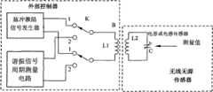
图1是本发明的无线无源测量电路的原理图。Fig. 1 is a schematic diagram of the wireless passive measurement circuit of the present invention.
图2是本发明的采用电容传感器的无线无源压力测量电路的原理图。Fig. 2 is a schematic diagram of a wireless passive pressure measurement circuit using a capacitive sensor of the present invention.
图3是本发明的采用电感传感器的无线无源位移测量电路的原理图。FIG. 3 is a schematic diagram of a wireless passive displacement measurement circuit using an inductance sensor according to the present invention.
具体实施方式Detailed ways
下面结合实施例和附图对本发明的无线无源物理量测量方法与电路做出详细说明。The wireless passive physical quantity measurement method and circuit of the present invention will be described in detail below in combination with the embodiments and the accompanying drawings.
实施例一:如图2所示,本发明的无线无源压力测量电路,电容压力传感器C与线圈L2构成并联谐振电路,而线圈L2与检测线圈L1又构成一个松耦合变压器B。测量时,先通过开关K将松耦合变压器B的检测线圈L1与脉冲激励信号发生器连接,外部电路由脉冲激励信号发生器产生一个脉冲信号,通过松耦合变压器B激励电容压力传感器C与线圈L2构成并联谐振电路,然后通过开关K将松耦合变压器B的检测线圈L1切换到谐振信号周期测量电路,测量谐振网络的振荡信号的周期,进而通过计算可以得到电容压力传感器所传感的压力值。Embodiment 1: As shown in FIG. 2, in the wireless passive pressure measurement circuit of the present invention, the capacitive pressure sensor C and the coil L2 form a parallel resonant circuit, and the coil L2 and the detection coil L1 form a loosely coupled transformer B. When measuring, first connect the detection coil L1 of the loosely coupled transformer B to the pulse excitation signal generator through the switch K, and the external circuit generates a pulse signal from the pulse excitation signal generator, and the loosely coupled transformer B excites the capacitive pressure sensor C and the coil L2 A parallel resonant circuit is formed, and then the detection coil L1 of the loosely coupled transformer B is switched to the resonant signal period measurement circuit through the switch K to measure the period of the oscillating signal of the resonant network, and then the pressure value sensed by the capacitive pressure sensor can be obtained by calculation.
计算过程为:The calculation process is:
电容传感器与线圈L2构成的并联谐振电路的谐振频率为:The resonant frequency of the parallel resonant circuit composed of capacitive sensor and coil L2 is:
或or
式中:L为线圈L2的电感值。即在L已知的条件下可以由检测到的f计算出C。而电容传感器的电容量:Where: L is the inductance value of the coil L2. That is, C can be calculated from the detected f under the condition that L is known. And the capacitance of the capacitive sensor:
C=F(P)C=F(P)
式中:P为被测压力值,F(P)是计算电容量C的函数。通常,可以选择线性较好的传感器,因而上式的函数关系又可以改写为In the formula: P is the measured pressure value, F(P) is the function of calculating the capacitance C. Usually, a sensor with better linearity can be selected, so the functional relationship of the above formula can be rewritten as
C=kP+C0C=kP+C0
式中:k为灵敏度系数,C0为电容传感器的0点值。或上式改写为In the formula: k is the sensitivity coefficient, andC0 is the 0-point value of the capacitance sensor. Or the above formula can be rewritten as
P=βC+P0P=βC+P0
式中:β=1/k为灵敏度系数,P0=-C0/k为电容传感器的0点值。最后可以计算出被测压力值P。In the formula: β=1/k is the sensitivity coefficient, P0 =-C0 /k is the 0-point value of the capacitive sensor. Finally, the measured pressure value P can be calculated.
实施例二:如图3所示,本发明的无线无源位移测量电路,电容C与电感位移传感器L2构成并联谐振电路,而电感位移传感器L2与检测线圈L1又构成一个松耦合变压器B。测量时,先通过开关K将松耦合变压器B的检测线圈L1与脉冲激励信号发生器连接,外部电路由脉冲激励信号发生器产生一个脉冲信号,通过松耦合变压器B激励电容C与电感位移传感器L2构成并联谐振电路,然后通过开关K将松耦合变压器B的线圈L1切换到谐振信号周期测量电路,测量谐振网络的振荡信号的周期,进而通过计算可以得到电感位移传感器所传感的位移值。Embodiment 2: As shown in FIG. 3 , in the wireless passive displacement measurement circuit of the present invention, the capacitor C and the inductive displacement sensor L2 form a parallel resonant circuit, and the inductive displacement sensor L2 and the detection coil L1 form a loosely coupled transformer B. When measuring, first connect the detection coil L1 of the loosely coupled transformer B to the pulse excitation signal generator through the switch K, and the external circuit generates a pulse signal from the pulse excitation signal generator, and the excitation capacitor C of the loosely coupled transformer B and the inductive displacement sensor L2 A parallel resonant circuit is formed, and then the coil L1 of the loosely coupled transformer B is switched to the resonant signal period measurement circuit through the switch K to measure the period of the oscillating signal of the resonant network, and then the displacement value sensed by the inductive displacement sensor can be obtained by calculation.
电容C与电感位移传感器L2构成的并联谐振电路的谐振频率为:The resonant frequency of the parallel resonant circuit composed of capacitor C and inductive displacement sensor L2 is:
或or
式中:即在C已知的条件下可以由检测到的f计算出L。而位移电感传感器L2的电感量:In the formula: That is, under the condition that C is known, L can be calculated from the detected f. And the inductance of the displacement inductance sensor L2:
L=F(X)L=F(X)
式中:X为被测位移值,F(X)是计算电感量L的函数。通常,可以选择线性较好的传感器,因而上式的函数关系又可以改写为Where: X is the measured displacement value, F(X) is the function of calculating the inductance L. Usually, a sensor with better linearity can be selected, so the functional relationship of the above formula can be rewritten as
L=kX+L0L=kX+L0
式中:k为灵敏度系数,L0为电感位移传感器的0点值。或上式改写为In the formula: k is the sensitivity coefficient, and L0 is the 0-point value of the inductive displacement sensor. Or the above formula can be rewritten as
X=βL+T0X=βL+T0
式中:β=1/k为灵敏度系数,X0=-L0/k为电感位移传感器的0点值。最后可以计算出被测位移值X。In the formula: β=1/k is the sensitivity coefficient, X0 =-L0 /k is the 0-point value of the inductive displacement sensor. Finally, the measured displacement value X can be calculated.
Claims (4)
Translated fromChinesePriority Applications (1)
| Application Number | Priority Date | Filing Date | Title |
|---|---|---|---|
| CN 201010510366CN102003973B (en) | 2010-10-19 | 2010-10-19 | Wireless passive measuring method and circuit |
Applications Claiming Priority (1)
| Application Number | Priority Date | Filing Date | Title |
|---|---|---|---|
| CN 201010510366CN102003973B (en) | 2010-10-19 | 2010-10-19 | Wireless passive measuring method and circuit |
Publications (2)
| Publication Number | Publication Date |
|---|---|
| CN102003973A CN102003973A (en) | 2011-04-06 |
| CN102003973Btrue CN102003973B (en) | 2013-01-23 |
Family
ID=43811529
Family Applications (1)
| Application Number | Title | Priority Date | Filing Date |
|---|---|---|---|
| CN 201010510366Expired - Fee RelatedCN102003973B (en) | 2010-10-19 | 2010-10-19 | Wireless passive measuring method and circuit |
Country Status (1)
| Country | Link |
|---|---|
| CN (1) | CN102003973B (en) |
Families Citing this family (15)
| Publication number | Priority date | Publication date | Assignee | Title |
|---|---|---|---|---|
| CN102507047A (en)* | 2011-09-30 | 2012-06-20 | 中北大学 | Non-contact passive sensor signal testing system |
| CN102944259B (en)* | 2012-10-25 | 2015-05-20 | 天津大学 | Wireless passive measuring device |
| CN103860160B (en)* | 2012-12-12 | 2016-06-15 | 中国科学院电子学研究所 | A kind of wireless and passive gastrointestinal stress detection system |
| CN103278181B (en)* | 2013-05-03 | 2016-03-16 | 东南大学 | A kind of wireless sensing circuit of passive LC resonator sensor |
| CN103575306A (en)* | 2013-11-18 | 2014-02-12 | 东南大学 | Passive wireless multi-parameter sensor system and multi-parameter measurement method thereof |
| CN103925944A (en)* | 2014-04-11 | 2014-07-16 | 东南大学 | Airtight spraying room environment monitoring system based on passive wireless sensing technology |
| WO2017025354A1 (en)* | 2015-08-11 | 2017-02-16 | Continental Teves Ag & Co. Ohg | Device for measuring a measurement variable |
| DE102015215331A1 (en) | 2015-08-11 | 2017-02-16 | Continental Teves Ag & Co. Ohg | Electronic control unit |
| WO2017041019A1 (en)* | 2015-09-02 | 2017-03-09 | Texas Instruments Incorporated | Inductive sensing with differential inductance readout based on sense/reference lc-ring oscillators with a shared capacitor |
| CN105702011A (en)* | 2016-01-19 | 2016-06-22 | 东南大学 | Passive wireless multiparameter sensing system switched by MEMS switch |
| DE102016202402A1 (en) | 2016-02-17 | 2017-08-17 | Continental Teves Ag & Co. Ohg | sensor |
| DE102016202403A1 (en) | 2016-02-17 | 2017-08-17 | Continental Teves Ag & Co. Ohg | sensor |
| CN105730600A (en)* | 2016-03-28 | 2016-07-06 | 苏州德佳物联科技有限公司 | Moment detecting system and motor control system |
| CN110332880B (en)* | 2019-07-24 | 2021-05-18 | 浙江矽瓷科技有限公司 | Wireless displacement sensor |
| CN111829559B (en)* | 2020-06-24 | 2022-07-08 | 东南大学 | A method for realizing multi-parameter measurement in a PT symmetrical LC passive wireless sensor system |
Citations (2)
| Publication number | Priority date | Publication date | Assignee | Title |
|---|---|---|---|---|
| CN2139695Y (en)* | 1992-12-30 | 1993-08-04 | 清华大学 | Contactless automatic speed temp. measuring device for rotating object |
| CN201964897U (en)* | 2010-10-19 | 2011-09-07 | 首都医科大学 | Wireless passive measuring circuit |
Family Cites Families (4)
| Publication number | Priority date | Publication date | Assignee | Title |
|---|---|---|---|---|
| US5433115A (en)* | 1993-06-14 | 1995-07-18 | Simmonds Precision Products, Inc. | Contactless interrogation of sensors for smart structures |
| CN1780581A (en)* | 2003-02-26 | 2006-05-31 | 马尔西奥·马克·奥雷利奥·马丁斯·阿布雷乌 | Apparatus and methods for measuring biological parameters |
| JP2009545356A (en)* | 2006-08-02 | 2009-12-24 | コーニンクレッカ フィリップス エレクトロニクス エヌ ヴィ | Sensor that detects the passage of pulse waves from the patient's arterial system |
| NL1033148C2 (en)* | 2006-12-29 | 2008-07-01 | Univ Delft Tech | Electric measuring device, method and computer program product. |
- 2010
- 2010-10-19CNCN 201010510366patent/CN102003973B/ennot_activeExpired - Fee Related
Patent Citations (2)
| Publication number | Priority date | Publication date | Assignee | Title |
|---|---|---|---|---|
| CN2139695Y (en)* | 1992-12-30 | 1993-08-04 | 清华大学 | Contactless automatic speed temp. measuring device for rotating object |
| CN201964897U (en)* | 2010-10-19 | 2011-09-07 | 首都医科大学 | Wireless passive measuring circuit |
Also Published As
| Publication number | Publication date |
|---|---|
| CN102003973A (en) | 2011-04-06 |
Similar Documents
| Publication | Publication Date | Title |
|---|---|---|
| CN102003973B (en) | Wireless passive measuring method and circuit | |
| CN103278181B (en) | A kind of wireless sensing circuit of passive LC resonator sensor | |
| Ye et al. | Studies of a high-sensitive surface acoustic wave sensor for passive wireless blood pressure measurement | |
| JP2020529893A5 (en) | ||
| WO2007079955A3 (en) | Analysis and compensation circuit for an inductive displacement sensor | |
| CN201964897U (en) | Wireless passive measuring circuit | |
| RU2004133897A (en) | TECHNOLOGICAL TRANSMITTER SENSOR WITH WIRELESS COMMUNICATION CHANNEL | |
| Cao et al. | A wireless strain sensor system for bladder volume monitoring | |
| CN106643826A (en) | Detection circuit and method of LC resonant transducer | |
| JP2012510631A (en) | Pressure measuring method and apparatus using magnetic characteristics | |
| Aldaoud et al. | Design of a miniaturized wireless blood pressure sensing interface using capacitive coupling | |
| WO2012021485A3 (en) | Method and apparatus for measuring fluid process variable in a well | |
| CN204514512U (en) | Based on the pressure unit of LC oscillatory circuit | |
| CN203231758U (en) | A Wireless Readout Circuit of Passive LC Resonant Sensor | |
| CN103512592B (en) | Wireless and passive LC resonant transducer testing circuit and corresponding information getting method | |
| CN102901440A (en) | Wireless sensory detection device and method for tunnel environment | |
| Zhang et al. | A self-powered instantaneous wireless sensing platform based on integrated triboelectric nanogenerator and negative resistance LC resonator | |
| CN102735152A (en) | Calibrating and measuring method of microwave absorbing coating thickness measuring instrument | |
| CN103925944A (en) | Airtight spraying room environment monitoring system based on passive wireless sensing technology | |
| CN104089720B (en) | Disconnect-type temperature measuring device | |
| CN103860160A (en) | Wireless passive gastrointestinal tract pressure detection system | |
| CN204422637U (en) | A kind of non-contact type high-voltage detecting device | |
| CN206002171U (en) | A kind of Ultrasonic Level Transmitter | |
| CN203443919U (en) | Weak magnetic inductor | |
| CN102334292B (en) | Voltage-frequency conversion circuit and blood pressure measurement apparatus provided with same |
Legal Events
| Date | Code | Title | Description |
|---|---|---|---|
| C06 | Publication | ||
| PB01 | Publication | ||
| C10 | Entry into substantive examination | ||
| SE01 | Entry into force of request for substantive examination | ||
| C14 | Grant of patent or utility model | ||
| GR01 | Patent grant | ||
| CF01 | Termination of patent right due to non-payment of annual fee | ||
| CF01 | Termination of patent right due to non-payment of annual fee | Granted publication date:20130123 |