CN101989763B - A power supply backup system, device and communication equipment - Google Patents
A power supply backup system, device and communication equipmentDownload PDFInfo
- Publication number
- CN101989763B CN101989763BCN2009101092885ACN200910109288ACN101989763BCN 101989763 BCN101989763 BCN 101989763BCN 2009101092885 ACN2009101092885 ACN 2009101092885ACN 200910109288 ACN200910109288 ACN 200910109288ACN 101989763 BCN101989763 BCN 101989763B
- Authority
- CN
- China
- Prior art keywords
- power supply
- power
- unit
- signal
- distribution board
- Prior art date
- Legal status (The legal status is an assumption and is not a legal conclusion. Google has not performed a legal analysis and makes no representation as to the accuracy of the status listed.)
- Active
Links
Images


Classifications
- Y—GENERAL TAGGING OF NEW TECHNOLOGICAL DEVELOPMENTS; GENERAL TAGGING OF CROSS-SECTIONAL TECHNOLOGIES SPANNING OVER SEVERAL SECTIONS OF THE IPC; TECHNICAL SUBJECTS COVERED BY FORMER USPC CROSS-REFERENCE ART COLLECTIONS [XRACs] AND DIGESTS
- Y02—TECHNOLOGIES OR APPLICATIONS FOR MITIGATION OR ADAPTATION AGAINST CLIMATE CHANGE
- Y02B—CLIMATE CHANGE MITIGATION TECHNOLOGIES RELATED TO BUILDINGS, e.g. HOUSING, HOUSE APPLIANCES OR RELATED END-USER APPLICATIONS
- Y02B70/00—Technologies for an efficient end-user side electric power management and consumption
- Y02B70/30—Systems integrating technologies related to power network operation and communication or information technologies for improving the carbon footprint of the management of residential or tertiary loads, i.e. smart grids as climate change mitigation technology in the buildings sector, including also the last stages of power distribution and the control, monitoring or operating management systems at local level
- Y—GENERAL TAGGING OF NEW TECHNOLOGICAL DEVELOPMENTS; GENERAL TAGGING OF CROSS-SECTIONAL TECHNOLOGIES SPANNING OVER SEVERAL SECTIONS OF THE IPC; TECHNICAL SUBJECTS COVERED BY FORMER USPC CROSS-REFERENCE ART COLLECTIONS [XRACs] AND DIGESTS
- Y04—INFORMATION OR COMMUNICATION TECHNOLOGIES HAVING AN IMPACT ON OTHER TECHNOLOGY AREAS
- Y04S—SYSTEMS INTEGRATING TECHNOLOGIES RELATED TO POWER NETWORK OPERATION, COMMUNICATION OR INFORMATION TECHNOLOGIES FOR IMPROVING THE ELECTRICAL POWER GENERATION, TRANSMISSION, DISTRIBUTION, MANAGEMENT OR USAGE, i.e. SMART GRIDS
- Y04S20/00—Management or operation of end-user stationary applications or the last stages of power distribution; Controlling, monitoring or operating thereof
- Y04S20/20—End-user application control systems
Landscapes
- Power Sources (AREA)
Abstract
Description
Translated fromChinese技术领域technical field
本发明涉及通信技术领域,尤其涉及一种供电备份系统、装置及通信设备。The invention relates to the technical field of communication, in particular to a power supply backup system, device and communication equipment.
背景技术Background technique
随着对各种通信设备的系统可靠性要求的提高,对设备的供电设计越来越被业界重视起来。以服务器设备为例,目前大多数服务器都采用多个电源来对服务器进行供电,当其中一个电源出现出现故障时,可以使用其他电源继续供电,以提高系统的可靠性。With the improvement of system reliability requirements for various communication devices, the power supply design for devices has been paid more and more attention by the industry. Taking server equipment as an example, most servers currently use multiple power supplies to supply power to the server. When one of the power supplies fails, other power supplies can be used to continue supplying power to improve system reliability.
参见图1,为现有技术采用1+1备份方式为服务器供电示意图。该供电方案中包括两个PSU(Power Supply Unit,电源供应单元)和一个PDB(PowerDistribution Board,配电板)。其中,PSU用于将输入的交流电源整流转换成直流电源,给服务器提供电源;PDB用于将多个PSU上的电源进行合路,同时,还可以完成电压转化、电源管理等功能。上述1+1备份方式表示使用1个PSU能满足系统需求(基本供电需求),同时有1个电源作备份使用。Referring to FIG. 1 , it is a schematic diagram of power supply for a server in a 1+1 backup mode in the prior art. The power supply scheme includes two PSU (Power Supply Unit, power supply unit) and a PDB (PowerDistribution Board, power distribution board). Among them, the PSU is used to rectify and convert the input AC power to DC power to provide power to the server; the PDB is used to combine the power on multiple PSUs, and at the same time, it can also complete functions such as voltage conversion and power management. The above 1+1 backup mode means that using 1 PSU can meet the system requirements (basic power supply requirements), and at the same time, there is 1 power supply for backup.
在采用该1+1备份方式时,两个PSU是同时工作的,在正常工作时,两个PSU都为服务器提供电源,当其中一个PSU出现故障不能提供电源时,启用另一个PSU为服务器提供电源。When using the 1+1 backup method, the two PSUs work simultaneously. During normal operation, both PSUs provide power to the server. When one of the PSUs fails and cannot provide power, the other PSU is activated to provide power supply.
发明人在实现本发明过程中发现现有技术至少存在如下缺点:The inventor finds that the prior art has at least the following shortcoming in the process of realizing the present invention:
由于采用备份方式给每个供电设备(如服务器)供电时至少需要两个PSU,因此,在实现对电源备份的同时相比单PSU供电方式增加了成本。Since at least two PSUs are required to supply power to each power supply device (such as a server) in the backup mode, the cost is increased compared with the single-PSU power supply mode while implementing power backup.
发明内容Contents of the invention
本发明实施例提供一种供电备份系统,包括:An embodiment of the present invention provides a power supply backup system, including:
第一电源模块,用于给第一设备供电,所述第一电源模块包括第一电源供应单元,第一配电板;The first power supply module is used to supply power to the first device, and the first power supply module includes a first power supply unit and a first distribution board;
第二电源模块,用于给第二设备供电,所述第二电源模块包括第二电源供应单元,第二配电板;The second power supply module is used to supply power to the second device, and the second power supply module includes a second power supply unit and a second distribution board;
所述第一配电板的电源信号与所述第二配电板的电源信号相连,使得所述第一电源供应单元和所述第二电源供应单元通过电源信号相连的所述第一配电板和所述第二配电板一起为所述第一设备和所述第二设备提供电源。The power signal of the first power distribution board is connected to the power signal of the second power distribution board, so that the first power distribution unit and the second power supply unit are connected through the power signal The board and the second power distribution board together provide power to the first device and the second device.
本发明实施例还提供了一种供电备份装置,用于给设备供电,包括:The embodiment of the present invention also provides a power supply backup device for supplying power to equipment, including:
电源供应单元,配电板;Power supply unit, distribution board;
所述配电板的电源信号与第二供电备份装置的第二配电板的电源信号相连;The power signal of the distribution board is connected with the power signal of the second distribution board of the second power supply backup device;
所述电源供应单元和所述第二供电备份装置的电源供应单元通过电源信号相连的所述第一配电板和所述第二配电板一起为所述设备和所述第二设备提供电源。The power supply unit and the power supply unit of the second power supply backup device are connected to the first distribution board and the second distribution board through a power signal to provide power for the device and the second device together .
以及,本发明实施例还提供了一种通信设备,包括本发明实施例提供的电备份系统,工作单元,通过所述供电备份系统为工作单元进行供电;And, the embodiment of the present invention also provides a communication device, including the power backup system provided by the embodiment of the present invention, and the working unit, which supplies power to the working unit through the power supply backup system;
所述通信设备为服务器,或者基站,或者网关。The communication device is a server, or a base station, or a gateway.
上述技术方案中具有如下的优点:The above technical solution has the following advantages:
通过将设备的配电板(PDB)之间的电源信号相连,可以使得每个设备只用一个电源供应单元(PSU)也能进行备份,与每个设备使用两个PSU的方案相比降低了成本。By connecting the power signals between the power distribution boards (PDBs) of the devices, it is possible to use only one power supply unit (PSU) for each device for backup, which is reduced compared with the solution of using two PSUs per device. cost.
附图说明Description of drawings
为了更清楚地说明本发明实施例中的技术方案,下面将对实施例或现有技术描述中所需要使用的附图作简单地介绍,显而易见地,下面描述中的附图仅仅是本发明的一些实施例,对于本领域普通技术人员来讲,在不付出创造性劳动的前提下,还可以根据这些附图获得其他的附图。In order to more clearly illustrate the technical solutions in the embodiments of the present invention, the following will briefly introduce the accompanying drawings that need to be used in the descriptions of the embodiments or the prior art. Obviously, the accompanying drawings in the following description are only of the present invention. For some embodiments, those of ordinary skill in the art can also obtain other drawings based on these drawings without any creative effort.
图1为现有技术通过两个电源供应单元进行供电的示意图;FIG. 1 is a schematic diagram of power supply through two power supply units in the prior art;
图2为本发明实施例供电备份系统结构示意图;Fig. 2 is a schematic structural diagram of a power supply backup system according to an embodiment of the present invention;
图3为本发明实施例直通单元结构示意图;FIG. 3 is a schematic structural diagram of a pass-through unit according to an embodiment of the present invention;
图4为本发明实施例金手指具体实现示意图;Fig. 4 is a schematic diagram of a specific implementation of a golden finger according to an embodiment of the present invention;
图5为本发明实施例供电备份系统中整合电源供应单元和直通单元时的结构示意图;FIG. 5 is a schematic structural diagram of integrating a power supply unit and a pass-through unit in a power supply backup system according to an embodiment of the present invention;
图6为本发明实施例通信设备结构示意图。FIG. 6 is a schematic structural diagram of a communication device according to an embodiment of the present invention.
具体实施方式Detailed ways
为使本发明的目的、技术方案及优点更加清楚明白,以下将通过具体实施例和相关附图,对本发明作进一步详细说明。In order to make the object, technical solution and advantages of the present invention clearer, the present invention will be further described in detail below through specific embodiments and related drawings.
实施例一Embodiment one
本发明实施例提供了一种供电备份系统,用于在实现供电备份时降低成本,包括:An embodiment of the present invention provides a power supply backup system for reducing costs when implementing power supply backup, including:
第一电源模块,用于给第一设备供电,所述第一电源模块包括第一电源供应单元,第一配电板;The first power supply module is used to supply power to the first device, and the first power supply module includes a first power supply unit and a first distribution board;
第二电源模块,用于给第二设备供电,所述第二电源模块包括第二电源供应单元,第二配电板;The second power supply module is used to supply power to the second device, and the second power supply module includes a second power supply unit and a second distribution board;
所述第一配电板的电源信号与所述第二配电板的电源信号相连,使得所述第一电源供应单元和所述第二电源供应单元通过电源信号相连的所述第一配电板和所述第二配电板一起为所述第一设备和所述第二设备提供电源。The power signal of the first power distribution board is connected to the power signal of the second power distribution board, so that the first power distribution unit and the second power supply unit are connected through the power signal The board and the second power distribution board together provide power to the first device and the second device.
所述第一配电板的控制信号和所述第二配电板的控制信号相连,所述控制信号为与控制总线相关的信号,如可以使用I2C总线、LPC总线或其他总线,各个总线控制信号并不相同,可以包括:The control signal of the first distribution board is connected with the control signal of the second distribution board, and the control signal is a signal related to the control bus, such as I2C bus, LPC bus or other bus can be used, each bus control Signals vary and can include:
总线时钟信号,或者总线数据信号,或者电压补偿信号,或者地远端补偿信号,或者均流信号中的一个或多个。One or more of a bus clock signal, or a bus data signal, or a voltage compensation signal, or a remote ground compensation signal, or a current sharing signal.
本发明实施例中,所述第一配电板的电源信号和控制信号与第一直通单元相连;In the embodiment of the present invention, the power signal and control signal of the first distribution board are connected to the first direct unit;
所述第二配电板的电源信号和控制信号与第二直通单元相连;The power signal and control signal of the second distribution board are connected to the second pass-through unit;
所述第一直通单元和所述第二直通单元通过电缆相连;The first through unit is connected to the second through unit through a cable;
第一和第二直通单元都包括配电板接口单元,电缆接口单元;Both the first and second pass-through units include a distribution board interface unit and a cable interface unit;
其中,所述配电板接口单元用于连接与直通单元对应的配电板;具体可以通过金手指或金牙齿进行连接;Wherein, the switchboard interface unit is used to connect the switchboard corresponding to the pass-through unit; specifically, the connection can be made through gold fingers or gold teeth;
所述电缆接口单元用于连接电缆,根据需要连接信号数据及电缆的接口类型,可以配置一个或多个接口与一根或多根电缆进行相连。The cable interface unit is used for connecting cables, and one or more interfaces can be configured to connect to one or more cables according to the interface type of signal data and cables required.
本发明实施例中,所述第一配电板的电源信号和控制信号与所述第二配电板的电源信号和控制信号也可以直接通过一直通单元相连,而不需要通过电缆进行相连,具体可通过直通单元中印刷电路板上的信号线将第一配电板的电源信号和控制信号与第二配电板的电源信号和控制信号相连。In the embodiment of the present invention, the power signal and control signal of the first power distribution board and the power signal and control signal of the second power distribution board may also be directly connected through a straight-through unit instead of a cable. Specifically, the power signal and control signal of the first distribution board may be connected with the power signal and control signal of the second distribution board through signal lines on the printed circuit board in the pass-through unit.
本发明实施例通过在设备的配电板(PDB)之间用直通单元相连,直通电源信号,可以使得每个设备只用一个电源供应单元(PSU)也能进行备份,与每个设备使用两个PSU的方案相比降低了成本。同时,每个设备与一个PSU相连还可以提升了PSU的输出效率,达到了节能减排的效果。In the embodiment of the present invention, by connecting the power distribution boards (PDBs) of the equipment with a through unit to pass through the power signal, each equipment can be backed up with only one power supply unit (PSU). Compared with the solution of a PSU, the cost is reduced. At the same time, each device connected to a PSU can also improve the output efficiency of the PSU, achieving the effect of energy saving and emission reduction.
系统实施例二System embodiment two
本发明系统实施例二提供了一种供电备份系统,用于在备份电源时降低成本。下面结合图2对本发明实施例作进一步说明。The second embodiment of the system of the present invention provides a power supply backup system, which is used to reduce the cost when backing up the power supply. The embodiment of the present invention will be further described below in conjunction with FIG. 2 .
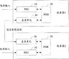
参见图2,为本发明实施例结构示意图,假设该供电备份系统用于为两个服务器进行供电,如图中服务器1和服务器2。每个服务器都包括PSU10(PowerSupply Unit,电源供应单元)、PDB20(Power Distribution Board,配电板),其中,PSU用于为供电设备(如图中的服务器)提供电源,例如,将交流电压转换成直流电压后通过PDB为服务器提供合适的电压;PDB的用于接收PSU的电源,将其输出送服务器,还可以完成电压的转换(如12V转5V、12V转3.3V等)、电源的控制管理等功能,在现有供电备份系统当中,每个供电设备中的PDB与两个PSU相连,以实现对电源的备份。Referring to FIG. 2 , which is a schematic structural diagram of an embodiment of the present invention, it is assumed that the power supply backup system is used to supply power to two servers, such as
本发明实施例中,将原有与PDB相连的两个PSU中的其中一个换成直通单元30,通过直通单元30将本服务器中的电源信号与另一服务器中的电源信号进行相连,此外,为了更好地对电源进行控制,本发明实施例还对一些控制信号进行直通;直通单元与直通单元之间通过电缆进行连接。In the embodiment of the present invention, one of the two PSUs originally connected to the PDB is replaced with a pass-through
直通单元在设计时可以是一块印刷电路板(这里指硬性印刷电路板)或柔性板(柔性印刷电路板),直通单元在印刷电路板或柔性板两者上的实现原理类似,本发明实施例以印刷电路板为例来对直通单元进行说明。The pass-through unit can be a printed circuit board (here referred to as a rigid printed circuit board) or a flexible board (flexible printed circuit board) when designing, and the realization principle of the pass-through unit on the printed circuit board or the flexible board is similar. The pass-through unit is described by taking the printed circuit board as an example.
参见图3,为直通单元的结构示意图,包括PDB接口单元和电缆接口单元。Referring to FIG. 3 , it is a schematic structural diagram of a pass-through unit, including a PDB interface unit and a cable interface unit.
其中,PDB接口单元可以通过金手指或金牙齿与PDB相连。由于PSU与PDB的接口在各个服务器供电系统中并没有固定统一的信号接口及实现形式,因此,可以针对不同的接口设计金手指或金牙齿的形状、内部各信号定义等。Wherein, the PDB interface unit can be connected to the PDB through gold fingers or gold teeth. Since the interface between the PSU and the PDB does not have a fixed and unified signal interface and implementation form in each server power supply system, the shape of the gold finger or gold tooth and the definition of internal signals can be designed for different interfaces.
本发明实施例中,直通单元与PDB连接的位置为原来PSU插槽(原先PSU与PDB连接的位置),当采用金手指或金牙齿与PDB相连时,可以使用原先插槽接口的所有信号,也可以只使用一部分需要使用的信号。In the embodiment of the present invention, the position where the pass-through unit is connected to the PDB is the original PSU slot (the original position where the PSU is connected to the PDB). When using gold fingers or gold teeth to connect to the PDB, all signals of the original slot interface can be used. It is also possible to use only a part of the signals that need to be used.
电缆接口单元用于使得两个服务器的直通单元之间通过电缆进行相连,电缆接口单元包括与电缆相连的接口,根据需要传送的信号的数量以及实际电缆接口的配置选择该接口的数量和类型。例如,如果需要传送3个信号,则可以只使用一根3PIN(3个引脚接口)电缆,与此对应,电缆接口只需要配置一个与3PIN电缆接口匹配的接口;如果需要传送7个信号,则可以配置一个与9PIN电缆接口匹配的接口(假设实际中没有与7PIN或8PIN电缆);如果需要传送12个信号,则可以使用一个与3PIN电缆接口匹配的接口和一个与9PIN电缆匹配的接口;也可以自定义一个12PIN或其他PIN数量的电缆并在电缆接口单元配置与该电缆匹配的接口。The cable interface unit is used to connect the straight-through units of two servers through cables. The cable interface unit includes interfaces connected to the cables. The number and type of the interfaces are selected according to the number of signals to be transmitted and the configuration of the actual cable interfaces. For example, if you need to transmit 3 signals, you can only use a 3PIN (3-pin interface) cable. Correspondingly, the cable interface only needs to be configured with an interface that matches the 3PIN cable interface; if you need to transmit 7 signals, Then you can configure an interface that matches the 9PIN cable interface (assuming that there is no 7PIN or 8PIN cable in practice); if you need to transmit 12 signals, you can use an interface that matches the 3PIN cable interface and an interface that matches the 9PIN cable; It is also possible to customize a 12PIN or other PIN cable and configure an interface matching the cable in the cable interface unit.
本发明实施例中,电缆接口单元使用3PIN和9PIN接口,其中3PIN接口用于传送电源信号,9PIN接口用于传送控制信号。In the embodiment of the present invention, the cable interface unit uses 3PIN and 9PIN interfaces, wherein the 3PIN interface is used to transmit power signals, and the 9PIN interface is used to transmit control signals.
通过直通单元直通的电源信号具体是指给服务器供电的的电源信号,包括工作电源、备用电源(Stand-by)、地等信号。其中,工作电源及备用电源的具体电压根据各服务器的要求会有所不同,如一些服务器要求工作电源12V、备用电源5V;另一些服务器要求工作电压48V、备用电源12V等。The power signal passed through through the pass-through unit specifically refers to a power signal for supplying power to the server, including signals such as working power, standby power (Stand-by), and ground. Among them, the specific voltage of the working power supply and backup power supply will vary according to the requirements of each server. For example, some servers require a working power supply of 12V and a backup power supply of 5V; other servers require a working voltage of 48V and a backup power supply of 12V.
通过直通单元直通的控制信号是PDB用于对电源进行管理而使用的信号。根据管理方式的不同,控制信号也会有所差别。本发明实施例当PDB采用I2C总线对电源进行管理时,控制信号包括I2C总线时钟信号(SMBus SCL)、I2C总线数据信号(SMBus SDA)等。当使用其他总线对接口对电源进行管理时,也可以针对该总线或接口对相应的信号进行直通。The control signal passed through by the pass-through unit is a signal used by the PDB to manage the power supply. Depending on the management method, the control signal will also be different. In the embodiment of the present invention, when the PDB adopts the I2C bus to manage the power supply, the control signal includes the I2C bus clock signal (SMBus SCL), the I2C bus data signal (SMBus SDA) and the like. When other buses are used to manage the power supply on the interface, the corresponding signals may also be passed through for the bus or the interface.
下面以PDB通过I2C总线对电源进行管理为例来对本发明实施例中的相关内容进行具体说明:The following takes PDB as an example to manage the power supply through the I2C bus to specifically describe the relevant content in the embodiment of the present invention:
当PDB通过I2C总线对电源进行管理时,本发明实施例可以对如下信号进行直通,具体参见表1:When the PDB manages the power supply through the I2C bus, the embodiment of the present invention can directly pass through the following signals, see Table 1 for details:
表1需要直通的信号及其功能和类型Table 1 Signals requiring pass-through and their functions and types

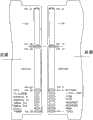
当对上述信号进行直通时,直通单元通过印刷电路板实现,直通单元的PDB接口采用金手指,参见图4,为金手指在电路板上的具体定义示意图,图4左侧部分表示电路板正面的金手指定义图,图4右侧部分表示电路板反面的金手指定义图,每个面上都设置有若干PIN(引脚),每个PIN对应于相应的信号,如PIN49-PIN62表示GROUND,PIN8表示RETURNS等。需要说明的是该金手指的形状以及其中信号的定义只是一个具体的实施例,在实际应用中可以根据具体接口的类型对PIN的数量和定义进行调整,如增加一些需要使用的信号或删除一些不需要使用的信号。When the above-mentioned signals are passed through, the pass-through unit is implemented through a printed circuit board, and the PDB interface of the pass-through unit uses a gold finger. See Figure 4, which is a schematic diagram of the specific definition of the gold finger on the circuit board. The left part of Figure 4 shows the front of the circuit board The right part of Figure 4 shows the gold finger definition diagram on the reverse side of the circuit board. There are several PINs (pins) on each surface, and each PIN corresponds to the corresponding signal. For example, PIN49-PIN62 means GROUND , PIN8 means RETURNS and so on. It should be noted that the shape of the gold finger and the definition of the signals therein are only a specific embodiment. In actual applications, the number and definition of PINs can be adjusted according to the type of specific interface, such as adding some signals that need to be used or deleting some Signals that do not need to be used.
为了节约成本,这里使用常用的具有3PIN端子的电缆和具有9PIN端子的电缆与电缆接口单元中的相应接口进行连接。In order to save cost, the commonly used cables with 3PIN terminals and cables with 9PIN terminals are used here to connect with corresponding interfaces in the cable interface unit.
参见图5,在另一实施例中,上述PSU、直通单元可以整合在一个设备中,如图中的电源备份单元中,此时,可以在该单元内部利用电路板上的信号线实现对信号的直通,省去用于连接两个直通单元的电缆。Referring to Fig. 5, in another embodiment, the above-mentioned PSU and the pass-through unit can be integrated into one device, such as the power backup unit in the figure, at this time, the signal line on the circuit board can be used to realize the signal connection inside the unit. pass-through, eliminating the need for cables to connect two pass-through units.
本发明实施例通过在设备的PDB之间用直通单元相连,直通电源信号,可以使得每个设备只用一个PSU也能进行备份,与每个设备使用两个PSU的方案相比降低了成本。同时,每个设备与一个PSU相连还可以提升了PSU的输出效率,达到了节能减排的效果。In the embodiment of the present invention, by connecting the PDBs of the equipment with a direct connection unit and passing through the power supply signal, each equipment can be backed up with only one PSU, which reduces the cost compared with the scheme of using two PSUs for each equipment. At the same time, each device connected to a PSU can also improve the output efficiency of the PSU, achieving the effect of energy saving and emission reduction.
实施例三Embodiment Three
本发明实施例三提供了一种供电备份装置,用于给设备供电,包括:Embodiment 3 of the present invention provides a power supply backup device for supplying power to equipment, including:
电源供应单元(PSU),配电板(PDB);Power Supply Unit (PSU), Power Distribution Board (PDB);
所述配电板的电源信号与第二供电备份装置的第二配电板的电源信号相连;The power signal of the distribution board is connected with the power signal of the second distribution board of the second power supply backup device;
所述电源供应单元和所述第二供电备份装置的电源供应单元通过有电源信号相连的所述第一配电板和所述第二配电板一起为所述设备和所述第二设备提供电源。The power supply unit of the power supply unit and the second power supply backup device provide power to the equipment and the second equipment through the first power distribution board and the second power distribution board connected with the power signal. power supply.
这里的电源信号根据设备需求而不同,如可以是12V、5Vsb和GROUDN等信号。The power signal here is different according to the requirements of the equipment, such as 12V, 5Vsb and GROUDN and other signals.
本发明实施例中,所述配电板的控制信号和所述第二配电板的控制信号相连,所述控制信号为与控制总线相关的信号,至少包括:In the embodiment of the present invention, the control signal of the distribution board is connected to the control signal of the second distribution board, and the control signal is a signal related to the control bus, at least including:
总线时钟信号,或者总线数据信号,或者电压补偿信号,或者地远端补偿信号,或者均流信号,当使用I2C总线进行通信时,可以包括12VLS、15Vcc(SB)、RETURNS、SMBUS SCL、SMBIS SDA、12VS等信号。Bus clock signal, or bus data signal, or voltage compensation signal, or remote ground compensation signal, or current sharing signal, when using I2C bus for communication, it can include 12VLS, 15Vcc (SB), RETURNS, SMBUS SCL, SMBIS SDA , 12VS and other signals.
具体地,所述配电板的电源信号和控制信号与第一直通单元相连;Specifically, the power supply signal and control signal of the distribution board are connected to the first direct unit;
所述第二配电板的电源信号和控制信号与第二直通单元相连;The power signal and control signal of the second distribution board are connected to the second pass-through unit;
所述第一直通单元和所述第二直通单元通过电缆相连;The first through unit is connected to the second through unit through a cable;
所述直通单元为印刷电路板,或者柔性板;这里的印刷电路板指的是一般硬性的印刷电路板,而柔性板指的是柔性印刷电路板。The pass-through unit is a printed circuit board or a flexible board; the printed circuit board here refers to a general rigid printed circuit board, and the flexible board refers to a flexible printed circuit board.
每个直通单元与配电板连接时可以通过金手指或金牙齿进行相连;Each pass-through unit can be connected to the distribution board through gold fingers or gold teeth;
优选地,直通单元与直通单元之间可以通过使用电缆进行灵活连接,电缆的接口可以根据实际信号线的数量选择具有合适PIN数量的电缆接口。Preferably, the through unit can be flexibly connected to the through unit by using a cable, and the interface of the cable can select a cable interface with a suitable number of PINs according to the actual number of signal lines.
本发明实施例通过将供电设备配电板(PDB)的电源信号与另一供电设备配电板的电源信号一起相连,使得两个供电设备的电源供应单元(PSU)通过有电源信号连接着的配电板一起为需要供电的设备提供电源,从而与为每个设备提供两个PSU进行供电的方案相比降低了成本。In the embodiment of the present invention, by connecting the power signal of the power distribution board (PDB) of the power supply device with the power signal of another power distribution board of the power supply device, the power supply units (PSU) of the two power supply devices are connected through the Together, the power distribution boards provide power to the devices that need power, reducing costs compared to providing power to each device with two PSUs.
实施例四Embodiment four
参见图6,本发明实施例四提供了一种通信设备60,包括供电备份系统61,工作单元62;其中,供电备份系统61采用实施例二所述的方式为工作单元62进行供电,该通信设备可以为服务器,或者基站,或者网关等。Referring to Fig. 6, Embodiment 4 of the present invention provides a
本发明实施例通信设备通过供电设备系统实行电源备份,可以使得每个需要供电的设备只需要用一个PSU也能备份,从而与每个设备使用两个PSU的方案相比降低了成本。同时,每个设备与一个PSU相连还可以提升了PSU的输出效率,达到了节能减排的效果。In the embodiment of the present invention, the communication device implements power backup through the power supply equipment system, so that each device that needs power supply can be backed up with only one PSU, thereby reducing the cost compared with the solution of using two PSUs for each device. At the same time, each device connected to a PSU can also improve the output efficiency of the PSU, achieving the effect of energy saving and emission reduction.
本领域普通技术人员可以理解实现上述实施例方法中的全部或部分流程,是可以通过计算机程序来指令相关的硬件来完成,所述的程序可存储于一计算机可读取存储介质中,该程序在执行时,可包括如上述各方法的实施例的流程。其中,所述的存储介质可为磁碟、光盘、只读存储记忆体(Read-Only Memory,ROM)或随机存储记忆体(Random Access Memory,RAM)等。Those of ordinary skill in the art can understand that all or part of the processes in the methods of the above embodiments can be implemented through computer programs to instruct related hardware, and the programs can be stored in a computer-readable storage medium. During execution, it may include the processes of the embodiments of the above-mentioned methods. Wherein, the storage medium may be a magnetic disk, an optical disk, a read-only memory (Read-Only Memory, ROM) or a random access memory (Random Access Memory, RAM), etc.
上列较佳实施例,对本发明的目的、技术方案和优点进行了进一步详细说明,所应理解的是,以上所述仅为本发明的较佳实施例而已,并不用以限制本发明,凡在本发明的精神和原则之内,所作的任何修改、等同替换、改进等,均应包含在本发明的保护范围之内。The above-listed preferred embodiments have further described the purpose, technical solutions and advantages of the present invention in detail. It should be understood that the above descriptions are only preferred embodiments of the present invention, and are not intended to limit the present invention. Within the spirit and principles of the present invention, any modifications, equivalent replacements, improvements, etc., shall be included within the protection scope of the present invention.
Claims (8)
Translated fromChinesePriority Applications (1)
| Application Number | Priority Date | Filing Date | Title |
|---|---|---|---|
| CN2009101092885ACN101989763B (en) | 2009-08-04 | 2009-08-04 | A power supply backup system, device and communication equipment |
Applications Claiming Priority (1)
| Application Number | Priority Date | Filing Date | Title |
|---|---|---|---|
| CN2009101092885ACN101989763B (en) | 2009-08-04 | 2009-08-04 | A power supply backup system, device and communication equipment |
Publications (2)
| Publication Number | Publication Date |
|---|---|
| CN101989763A CN101989763A (en) | 2011-03-23 |
| CN101989763Btrue CN101989763B (en) | 2013-10-09 |
Family
ID=43746167
Family Applications (1)
| Application Number | Title | Priority Date | Filing Date |
|---|---|---|---|
| CN2009101092885AActiveCN101989763B (en) | 2009-08-04 | 2009-08-04 | A power supply backup system, device and communication equipment |
Country Status (1)
| Country | Link |
|---|---|
| CN (1) | CN101989763B (en) |
Families Citing this family (11)
| Publication number | Priority date | Publication date | Assignee | Title |
|---|---|---|---|---|
| CN103312022A (en)* | 2012-03-06 | 2013-09-18 | 北京联动天翼科技有限公司 | Machine room distributed power supply system |
| CN103094896A (en)* | 2013-02-04 | 2013-05-08 | 南京丰泰通信技术股份有限公司 | Low-voltage direct current power pack used for communication equipment group and backup method thereof |
| CN105978128A (en)* | 2016-06-23 | 2016-09-28 | 浪潮电子信息产业股份有限公司 | Power supply module, power supply system and power supply method |
| CN107844185B (en)* | 2016-09-19 | 2020-01-31 | 华为数字技术(成都)有限公司 | power supply management method and device |
| CN106708236A (en)* | 2016-12-15 | 2017-05-24 | 郑州云海信息技术有限公司 | Redundant power source management system and control method |
| CN106774773B (en)* | 2017-03-27 | 2020-10-27 | 联想(北京)有限公司 | Power supply device of server |
| CN107222019A (en)* | 2017-06-09 | 2017-09-29 | 郑州云海信息技术有限公司 | A kind of electric power system and method for improving container data center Distribution level |
| CN109814697B (en)* | 2017-11-21 | 2023-02-10 | 佛山市顺德区顺达电脑厂有限公司 | Power supply method for computer system |
| CN108681387B (en)* | 2018-05-16 | 2021-06-29 | 郑州云海信息技术有限公司 | A power board timing method |
| TWI754941B (en)* | 2020-05-27 | 2022-02-11 | 宏正自動科技股份有限公司 | Electronic equipment and operation method thereof |
| CN112332641A (en)* | 2020-10-30 | 2021-02-05 | 苏州浪潮智能科技有限公司 | A power supply system, power supply method and electronic device |
Citations (4)
| Publication number | Priority date | Publication date | Assignee | Title |
|---|---|---|---|---|
| CN1481061A (en)* | 2002-09-06 | 2004-03-10 | 华为技术有限公司 | A power supply module for communication equipment |
| CN101068387A (en)* | 2007-05-19 | 2007-11-07 | 李峰 | Rural area middle and small size communication transmission base station power supply device and method thereof |
| CN101165988A (en)* | 2006-10-16 | 2008-04-23 | 康弗蒂姆有限公司 | Power distribution systems |
| US7423355B2 (en)* | 2004-12-20 | 2008-09-09 | Fujitsu Limited | Power controller, apparatus provided with backup power supply, program for controlling power, and method for controlling power |
- 2009
- 2009-08-04CNCN2009101092885Apatent/CN101989763B/enactiveActive
Patent Citations (4)
| Publication number | Priority date | Publication date | Assignee | Title |
|---|---|---|---|---|
| CN1481061A (en)* | 2002-09-06 | 2004-03-10 | 华为技术有限公司 | A power supply module for communication equipment |
| US7423355B2 (en)* | 2004-12-20 | 2008-09-09 | Fujitsu Limited | Power controller, apparatus provided with backup power supply, program for controlling power, and method for controlling power |
| CN101165988A (en)* | 2006-10-16 | 2008-04-23 | 康弗蒂姆有限公司 | Power distribution systems |
| CN101068387A (en)* | 2007-05-19 | 2007-11-07 | 李峰 | Rural area middle and small size communication transmission base station power supply device and method thereof |
Non-Patent Citations (1)
| Title |
|---|
| JP特开2005-261116A 2005.09.22 |
Also Published As
| Publication number | Publication date |
|---|---|
| CN101989763A (en) | 2011-03-23 |
Similar Documents
| Publication | Publication Date | Title |
|---|---|---|
| CN101989763B (en) | A power supply backup system, device and communication equipment | |
| US10409753B2 (en) | Adapters, systems and methods for adapting PCIe expansion cards to PCIe component bays | |
| CN106873725A (en) | Device bearing device, conversion board and method for refreshing cache memory | |
| CN209265383U (en) | A power adapter board for server | |
| CN107291201A (en) | A kind of server power panel | |
| CN104267782A (en) | Low-power-consumption 18-tube yunfile node device | |
| CN101930276A (en) | A method for realizing mainboard power supply through hot-swapping technology | |
| CN103885034A (en) | Digital signal processing device for radar | |
| CN108009115A (en) | A kind of binode server board with clock redundancy feature | |
| CN106502363A (en) | A kind of electric power system of multi-node server system | |
| CN102375521A (en) | Computer system | |
| CN207319223U (en) | Computing switching device based on PCIE X16-MXM | |
| CN107391332A (en) | A kind of storage system and debugging system | |
| CN201540505U (en) | Combined computer motherboard | |
| US20130120924A1 (en) | Power supply system for memory modules and adapter board thereof | |
| CN108182155A (en) | It is a kind of reduce cost manage M.2 back plate design method | |
| CN104679123A (en) | Mainboard and data burning method thereof | |
| CN113986809A (en) | Depth computation processor board card and interconnection system for depth computation processor board cards | |
| CN214256754U (en) | PCB connecting plate module for data synchronization of fault-tolerant computer | |
| CN206805526U (en) | A kind of PCIE BOX switching boards applied on the server | |
| CN205540464U (en) | High -end server striking machine case power bottom plate | |
| CN206235979U (en) | A kind of overall board applied in purley Platform Servers | |
| CN222125681U (en) | A transfer board | |
| CN111949586A (en) | Expansion board based on Nvidia Jetson Nano/Xavier NX core board | |
| CN205353855U (en) | Embedded computer main board |
Legal Events
| Date | Code | Title | Description |
|---|---|---|---|
| C06 | Publication | ||
| PB01 | Publication | ||
| C10 | Entry into substantive examination | ||
| SE01 | Entry into force of request for substantive examination | ||
| C14 | Grant of patent or utility model | ||
| GR01 | Patent grant |