CN101985327B - Hard open top container - Google Patents
Hard open top containerDownload PDFInfo
- Publication number
- CN101985327B CN101985327BCN2009100901454ACN200910090145ACN101985327BCN 101985327 BCN101985327 BCN 101985327BCN 2009100901454 ACN2009100901454 ACN 2009100901454ACN 200910090145 ACN200910090145 ACN 200910090145ACN 101985327 BCN101985327 BCN 101985327B
- Authority
- CN
- China
- Prior art keywords
- locking
- bar
- plate
- top cover
- hole
- Prior art date
- Legal status (The legal status is an assumption and is not a legal conclusion. Google has not performed a legal analysis and makes no representation as to the accuracy of the status listed.)
- Expired - Fee Related
Links
- 238000009434installationMethods0.000claims1
- 230000000903blocking effectEffects0.000abstractdescription12
- 238000007789sealingMethods0.000abstractdescription6
- 230000007306turnoverEffects0.000abstract1
- 238000000034methodMethods0.000description6
- 238000010586diagramMethods0.000description5
- 230000002441reversible effectEffects0.000description2
- 238000012986modificationMethods0.000description1
- 230000004048modificationEffects0.000description1
Images


Landscapes
- Closures For Containers (AREA)
Abstract
Description
Translated fromChinese技术领域technical field
本发明涉及一种硬开顶集装箱。The invention relates to a hard open top container.
背景技术Background technique
硬开顶集装箱是一种从顶部装卸货物的运输存储容器,其通常包括底架、分别固定在该底架四边的四个侧板、以及用于封闭该硬开顶集装箱顶部的顶盖。其中,所述四个侧板两两相对,并且每个侧板均可以设置为墙板的形式或者门板的形式。这样,底架、侧板和顶盖之间就限定了用于放置货物的容纳空间。通常,在硬开顶集装箱上还设有锁紧机构,当锁紧机构处于打开状态时,顶盖可以从侧板上移除以装/卸货物;当锁紧机构处于锁紧状态时,顶盖相对于侧板固定,从而保证了箱内货物的安全。A hard open top container is a transport storage container for loading and unloading goods from the top, which generally includes a bottom frame, four side panels respectively fixed on the four sides of the bottom frame, and a top cover for closing the top of the hard open top container. Wherein, the four side panels are opposite in pairs, and each side panel can be set in the form of a wall panel or a door panel. In this way, an accommodating space for placing goods is defined between the bottom frame, the side panels and the top cover. Usually, there is also a locking mechanism on the hard open top container. When the locking mechanism is in the open state, the top cover can be removed from the side plate to load/unload the goods; when the locking mechanism is in the locked state, the top cover The cover is fixed relative to the side panels, thus ensuring the safety of the contents of the box.
但是,目前普通硬开顶集装箱的锁紧机构通常仅可通过侧面锁紧,或仅可通过顶部锁紧。因此,其顶盖与侧板之间的锁定稳定性并不高,而且操作较为繁琐。However, the locking mechanism of the common hard open top container can only be locked by the side or only by the top at present. Therefore, the locking stability between the top cover and the side plate is not high, and the operation is relatively cumbersome.
发明内容Contents of the invention
本发明的所要解决的技术问题在于提供一种硬开顶集装箱,其具有侧部锁紧机构和顶部锁紧机构,能实现顶部和侧部都可进行锁紧与打开的操作,更好地解决硬开顶集装箱锁紧装置的操作性。The technical problem to be solved by the present invention is to provide a hard open top container, which has a side locking mechanism and a top locking mechanism, which can realize the locking and opening operations of both the top and the sides, and better solve the problem of Operability of locking devices for hard open top containers.
为了实现上述目的,本发明提供一种硬开顶集装箱,包括底架、分别设置在该底架四边的四个侧板、以及用于封闭该硬开顶集装箱顶部的顶盖,其特点在于,所述顶盖与至少一所述侧板之间设置有至少一锁紧装置,该锁紧装置包括:侧部锁紧机构,设置于至少一所述侧板外侧,其包含有侧锁杆,可上下移动并绕自身轴线转动地固定在该侧板上,且其顶端具有与之相垂直的侧挡杆,该侧挡杆在被转动至一第一位置时与该侧板平行,而在被转动至一第二位置时与该侧板垂直;顶部锁紧机构,设置于该顶盖顶部,其包含有顶锁杆,其通过一转动轴可转动地安装在该顶盖顶部上并可以该转动轴为轴上下翻转,该顶锁杆一端设置有锁紧凹部,该锁紧凹部在该侧挡杆位于该第一位置时与之配合锁紧而使该顶盖与该侧板锁紧连接,而在该侧挡杆位于该第二位置时与之脱离连接而使该顶盖与该侧板脱离连接。In order to achieve the above object, the present invention provides a hard open top container, comprising a bottom frame, four side panels respectively arranged on the four sides of the bottom frame, and a top cover for closing the top of the hard open top container, which is characterized in that, At least one locking device is provided between the top cover and at least one of the side plates, and the locking device includes: a side locking mechanism, disposed outside at least one of the side plates, which includes a side locking bar, It can move up and down and is fixed on the side plate so that it can rotate around its own axis, and its top end has a side bar that is perpendicular to it. The side bar is parallel to the side plate when it is rotated to a first position, and when When it is rotated to a second position, it is perpendicular to the side plate; the top locking mechanism is arranged on the top of the top cover, which includes a top lock lever, which is rotatably installed on the top of the top cover through a rotating shaft and can The rotating shaft is turned up and down, and one end of the top locking lever is provided with a locking concave part, and the locking concave part cooperates with it when the side bar is at the first position to lock the top cover and the side plate connected, and when the side bar is in the second position, it is disconnected so that the top cover is disconnected from the side panel.
在本发明一实施例中,该顶部锁紧机构还包括一用于在该顶盖与该侧板处于锁紧连接时固定该顶锁杆使该锁紧凹部不旋转脱离该侧挡杆的顶锁杆固定装置。In one embodiment of the present invention, the top locking mechanism further includes a top for fixing the top locking bar so that the locking recess does not rotate out of the side bar when the top cover is in locked connection with the side plate. Lock bar fixture.
较佳的,该顶锁杆固定装置包括:一穿孔,设置于该顶锁杆另一端的一预定位置上;一第一锁固板,对应于该穿孔固定在该顶盖上,且其上具有第一锁孔,该第一锁固板在该顶盖与该侧板处于锁紧连接时穿过该穿孔,且该第一锁孔位于该顶锁杆上方;一第二锁固板,其一端通过固定于该顶盖上的第一旋转轴可旋转地安装在该顶锁杆一侧,其另一端具有第二锁孔,该第二锁固板可以该第一旋转轴为轴在一固定位置和一脱开位置间转动,在该固定位置时,该第二锁固板在该顶锁杆上方被旋转至与该第一锁固板通过该第二锁孔与该第一锁孔的配合卡接,在该脱开位置时,该第二锁固板被旋转至该顶锁杆一侧与该第一锁固板脱离连接而暴露出该顶锁杆。Preferably, the locking rod fixing device includes: a through hole, which is arranged at a predetermined position at the other end of the locking rod; a first locking plate, which is fixed on the top cover corresponding to the through hole, and on which There is a first locking hole, the first locking plate passes through the through hole when the top cover and the side plate are in locked connection, and the first locking hole is located above the top locking rod; a second locking plate, Its one end is rotatably installed on one side of the top locking lever through the first rotating shaft fixed on the top cover, and its other end has a second locking hole, and the second locking plate can be pivoted on the first rotating shaft. Rotate between a fixed position and a disengagement position. In the fixed position, the second locking plate is rotated above the top lock bar to connect with the first locking plate through the second locking hole and the first lock. When the holes are snapped together, in the disengaged position, the second locking plate is rotated to one side of the top locking bar and is disconnected from the first locking plate to expose the top locking bar.
较佳的,该顶锁杆固定装置还包括:第一限位板,设置于该第二锁固板一端,且其上具有第一限位孔;第二限位板,其一端通过第二旋转轴可旋转的安装在该顶盖上,另一端则具有第二限位孔,在该第二锁固板处于该固定位置时,该第二限位板可被旋转至该第二限位孔与该第一限位孔对齐,并通过一销轴固定,限制该第二锁固板与该第一锁固板保持卡接。Preferably, the locking rod fixing device further includes: a first limiting plate, which is arranged at one end of the second locking plate, and has a first limiting hole; a second limiting plate, one end of which passes through the second The rotating shaft is rotatably mounted on the top cover, and the other end has a second limit hole. When the second locking plate is at the fixed position, the second limit plate can be rotated to the second limit The hole is aligned with the first limiting hole, and is fixed by a pin shaft, so as to limit the second locking plate and the first locking plate to maintain engagement.
在本发明一实施例中,该侧锁杆垂直连接于该侧挡杆的中部,将该侧挡杆分为分别位于该侧锁杆两侧的第一连接部和第二连接部。In one embodiment of the present invention, the side locking bar is vertically connected to the middle part of the side blocking bar, and the side blocking bar is divided into a first connecting part and a second connecting part respectively located on two sides of the side locking bar.
较佳的,该锁紧凹部由两个间隔一间隙相对设置的第一锁紧部和第二锁紧部构成,该第一锁紧部和第二锁紧部上分别形成有第一凹槽和第二凹槽,在该侧挡杆位于该第一位置时,该第一凹槽和第二凹槽分别与该第一连接部和第二连接部配合锁紧;在该侧挡杆位于该第二位置时,该侧挡杆位于该间隙内。Preferably, the locking recess is composed of two first locking parts and second locking parts oppositely arranged at a gap, and first grooves are respectively formed on the first locking parts and the second locking parts and the second groove, when the side bar is in the first position, the first groove and the second groove are locked with the first connecting part and the second connecting part respectively; when the side bar is in the In the second position, the side bar is located in the gap.
在本发明一实施例中,该侧板的顶梁对应于该侧锁杆的位置设置有用于安装该侧锁杆的安装孔。In an embodiment of the present invention, the top beam of the side plate is provided with a mounting hole for mounting the side locking rod at a position corresponding to the side locking rod.
在本发明一实施例中,该侧部锁紧机构还包括用于在该顶盖与该侧板处于锁紧连接时固定该侧锁杆的侧锁杆固定装置。In an embodiment of the present invention, the side locking mechanism further includes a side locking bar fixing device for fixing the side locking bar when the top cover and the side plate are in locking connection.
本发明通过侧部锁紧机构与顶部锁紧机构的配合,使硬开顶集装箱的锁紧装置的操作更简单、可靠,且能通过侧面及顶部任意一种锁紧方式进行锁紧操作。Through the cooperation of the side locking mechanism and the top locking mechanism, the invention makes the operation of the locking device of the hard open top container simpler and more reliable, and can perform locking operation through any locking method of the side and the top.
以下结合附图和具体实施例对本发明进行详细描述,但不作为对本发明的限定。The present invention will be described in detail below in conjunction with the accompanying drawings and specific embodiments, but not as a limitation of the present invention.
附图说明Description of drawings
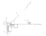
图1为本发明的硬开顶集装箱的顶盖与侧板之间的锁紧装置的结构示意图,其中顶部锁紧机构与侧部锁紧机构配合锁紧;Fig. 1 is a structural schematic diagram of the locking device between the top cover and the side plate of the hard open top container of the present invention, wherein the top locking mechanism and the side locking mechanism cooperate and lock;
图2为图1的锁紧装置的俯视示意图,其中侧部锁紧机构的侧锁杆顶端的侧挡杆与顶部锁紧机构的顶锁杆一端的锁紧凹部配合锁紧;Fig. 2 is a top view schematic diagram of the locking device of Fig. 1, wherein the side stop bar at the top of the side locking bar of the side locking mechanism cooperates and locks with the locking recess at one end of the top locking bar of the top locking mechanism;
图3为本发明锁紧装置的一较佳打开方式的示意图,其是在锁紧状态下,拉起顶锁杆,并将侧锁杆旋转90度,使顶锁杆与侧锁杆断开连接,进而使顶盖成打开状态;Fig. 3 is a schematic diagram of a preferred opening mode of the locking device of the present invention, which is to pull up the top lock lever in the locked state, and rotate the side lock lever 90 degrees, so that the top lock lever and the side lock lever are disconnected Connect, and then make the top cover open;
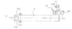
图4为图3的锁紧装置断开连接的状态示意图;Fig. 4 is a schematic diagram of a state in which the locking device of Fig. 3 is disconnected;
图5为本发明锁紧装置的另一较佳打开方式的示意图,其是在锁紧状态下,提起侧锁杆后旋转90度,使顶锁杆与侧锁杆断开连接,进而使顶盖成打开状态。Fig. 5 is a schematic diagram of another preferred opening mode of the locking device of the present invention, which is to lift the side lock lever and rotate it 90 degrees in the locked state, so that the top lock lever is disconnected from the side lock lever, and then the top lock lever is opened. Cover is left open.
具体实施方式Detailed ways
本发明的硬开顶集装箱通常包括底架、分别固定在该底架四边的四个侧板、以及用于封闭该硬开顶集装箱顶部的顶盖。其中,这四个侧板两两相对,并且每个侧板可以根据需要被设置为墙板的形式或者可开启的门板的形式。在该顶盖与任一侧板之间,还可以通过至少一锁紧装置进行锁紧。在以下的实施例中,仅以其中一侧板与该顶盖之间的一锁紧装置为例对该锁紧装置进行详细描述,但可以理解的是,本领域技术人员当可根据实际需要,对锁紧装置的设置数目和位置进行不同设计,以满足不同需要,这些并不作为对本发明的限制。The hard open top container of the present invention usually includes a bottom frame, four side panels respectively fixed on the four sides of the bottom frame, and a top cover for closing the top of the hard open top container. Wherein, the four side panels are opposite in pairs, and each side panel can be set in the form of a wall panel or an openable door panel as required. Between the top cover and any side plate, at least one locking device can also be used for locking. In the following embodiments, only a locking device between one side plate and the top cover is used as an example to describe the locking device in detail, but it can be understood that those skilled in the art can , different designs are made on the number and positions of the locking devices to meet different needs, which are not intended to limit the present invention.
如图1、2所示,在本发明一实施例中,本发明较特别的是,在侧板10与顶盖20之间设置有锁紧装置,该锁紧装置包括侧部锁紧机构30和顶部锁紧机构40,通过二者的配合可实现侧板10与顶盖20之间的锁紧或打开。As shown in Figures 1 and 2, in one embodiment of the present invention, the present invention is more particularly that a locking device is provided between the
在本发明一实施例中,该侧部锁紧机构30设置于该侧板10的外侧,其可包含有侧锁杆31,且该侧锁杆31的顶端具有与之相垂直的侧挡杆32。该侧锁杆31可上下移动并绕自身轴线I转动地固定在该侧板10上。当该侧锁杆31被转动至一第一位置时,其顶端的侧挡杆32与该侧板10平行(参考图1),当该侧锁杆31被转动至一第二位置时,其顶端的侧挡杆32与该侧板垂直(参考图3)。在本发明一实施例中,该侧锁杆31较佳的垂直连接于该侧挡杆32的中部,从而将该侧挡杆32分成分别为与该侧锁杆31两侧的第一连接部321和第二连接部322。在本发明一较佳实施例中,该侧板10的顶梁11对应于该侧锁杆31的位置设置有用于安装该侧锁杆31的安装孔13,以限制侧锁杆31垂直地上下移动。在本发明的另一较佳实施例中,该顶盖40的边梁21内还可设置密封件22,如密封胶条,用以在顶盖40盖合时与侧板10的顶梁11的内侧面紧密接触,从而实现箱体的密封。In one embodiment of the present invention, the
在本发明一实施例中,该顶部锁紧机构40设置于该顶盖20顶部,其可包含有顶锁杆41,该顶锁杆41通过一转动机构可上下翻转地安装在顶盖20上,该转动机构例如包括:设在该顶盖20靠近该侧锁杆31一侧的顶边梁21上的固定座51、穿过该固定座51上的安装孔(图中未标示)和对应设置于该顶锁杆41预定位置上的安装孔(图中未标示)的一转动轴54、以及在该顶锁杆41两侧与该转动轴54锁紧固定的螺母55等。通过该固定座51、转动轴54、螺母55配合,即可将顶锁杆41可转动地安装,使其可以该转动轴54为轴上下翻转。在该顶锁杆41一端还具有锁紧凹部43,其具有用于与该侧挡杆32配合锁紧的凹槽430,而该顶锁杆41的另一端可弯折形成一相对较高的把手47,以便于操作顶锁杆41。与该侧挡杆32的结构相对应的是,该锁紧凹部43可由两个间隔一间隙433相对设置的第一锁紧部431和第二锁紧部432构成,该第一锁紧部431、第二锁紧部432上分别设置有所述凹槽430(即第一凹槽、第二凹槽),用以分别与该侧挡杆32的第一连接部321、第二连接部322配合锁紧连接。In one embodiment of the present invention, the
如图1所示,当侧锁杆31被转动至其侧挡杆32与该侧板10平行的第一位置时,通过该顶锁杆41一端的锁紧凹部43与该侧挡杆32配合,具体的说是通过锁紧凹部43的第一连接部431、第二连接部432上的凹槽430分别与该侧挡杆32的第一连接部321、第二连接部322配合,使顶盖20与侧板10之间实现锁紧连接,此时顶锁杆41处于水平位置。锁紧后的顶盖20封闭了硬开顶集装箱的顶部。较佳的,还可以在顶盖20的四个顶边梁内设置密封结构,如密封片22以密封箱体。As shown in Figure 1, when the
当需要打开顶盖20时,如图3所示,首先,向上拉起顶锁杆41,使锁紧凹部43与侧挡杆32断开连接。然后,将侧锁杆31旋转90度,使其顶端的侧挡杆32转动90度,此时该侧档杆32位置是垂直于侧板10的位置,从而使侧挡杆32处于该锁紧凹部43的第一锁紧部431、第二锁紧部432之间的间隙433内,如图4所示,此时即可将顶盖20打开。When the
在本发明另一实施例中,该侧部锁紧机构30还可包括一侧锁杆固定装置(图中未示),用以在该侧板10与该顶盖20处于锁紧连接时固定该侧锁杆31,使其不会发生意外转动,确保其顶端的侧挡杆32保持与该侧板10平行。在本发明中,该侧锁杆固定装置可以是不同的固定结构,只要其可保证该侧锁杆31在锁紧状态下可被固定,而在打开该固定装置时可使得侧锁杆上下移动和绕自身轴线转动即可。In another embodiment of the present invention, the
而在本发明另一实施例中,该顶部锁紧机构40还可包括一顶锁杆固定装置60,用于在该顶盖20与该侧板10处于锁紧连接时固定该顶锁杆41,使该锁紧凹部43不旋转脱离该侧挡杆32。结合参考图1、2、4,该顶锁杆固定装置60可包括:一穿孔46,设置于该顶锁杆41另一端的一预定位置上;一第一锁固板61,对应于该穿孔46固定在该顶盖10上,且其上具有第一锁孔611;一第二锁固板62,其一端通过固定于该顶盖20上的第一旋转轴622可旋转地安装在该顶锁杆41一侧,其另一端具有第二锁孔621。该第二锁固板62可以该第一旋转轴622为轴在一固定位置(如图2所示)和一脱开位置(如图4所示)间转动。当顶盖20与侧板10之间处于锁紧连接状态时,该顶锁杆41处于水平位置,此时该第一锁固板61恰好穿过该顶锁杆41上的穿孔46,且其上的第一锁固孔611位于该顶锁杆41的上方,在该顶锁杆41上方将该第二锁固板62旋转至其上的第二锁固孔621与与该第一锁孔611配合卡接,从而可以固定该顶锁杆41处于锁紧连接状态,即该顶锁杆固定装置60处于固定位置。In another embodiment of the present invention, the
为了进一步确保该顶锁杆固定装置60的锁固可靠性,该顶锁杆固定装置60较佳的还可包括第一限位板63和第二限位板64。该第一限位板63设置于第二锁固板62一端,且其上还设置有第一限位孔631。该第二限位板64一端通过第二旋转轴642可旋转的安装在该顶盖20上,另一端则具有第二限位孔641。在该第二锁固板62处于该固定位置时,该第二限位板64可被旋转至该第二限位孔641与该第一限位孔641对齐,并通过一销轴(图中未示)固定,以限制该第二锁固板62与该第一锁固板61保持卡接。In order to further ensure the locking reliability of the jacking
当需要打开顶盖时,可以先打开该顶锁杆固定装置60,如图4所示,先断开第一限位板63和第二限位板64的连接,然后旋转第二锁固板62,使之被旋转至该顶锁杆41一侧并与该第一锁固板61脱离连接,从而暴露出该顶锁杆41,即处于脱开位置。然后继续如图3所示的拉起顶锁杆41的动作和旋转侧锁杆31的动作,如此即可打开顶盖20。When the top cover needs to be opened, the top lock
上述示出了本发明打开顶盖的一种操作方法,上述打开操作方法的相反步骤即可实现顶盖与侧板的锁紧操作,在此不再赘述。The above shows an operation method for opening the top cover of the present invention, and the reverse steps of the above opening operation method can realize the locking operation of the top cover and the side panels, which will not be repeated here.
本发明的另一种打开顶盖的操作方法是,在锁紧状态下,提起侧锁杆31,如图5所示,然后将其旋转90度,使侧挡杆32位于该顶锁杆41的第一锁紧部431和第二锁紧部432之间的间隙433内(可参考图4),此时即可将顶盖20打开。同样,上述打开顶盖的操作方法的反向动作即为锁紧操作,在此不再赘述。Another operation method for opening the top cover of the present invention is to lift the
因此,本发明通过该侧部锁紧机构和顶部锁紧机构的配合,将能使硬开顶集装箱的锁紧装置的操作更简单,可靠,且能通过侧面和顶部任意一种锁紧/打开方式进行锁紧/打开操作。Therefore, through the cooperation of the side locking mechanism and the top locking mechanism, the present invention can make the operation of the locking device of the hard open top container simpler and more reliable, and can be locked/opened by any one of the side and the top. lock/unlock operation.
当然,本发明还可有其他多种实施例,在不背离本发明精神及其实质的情况下,熟悉本领域的技术人员当可根据本发明作出各种相应的改变和变型,但这些相应的改变和变形都应属于本发明所附的权利要求的保护范围。Certainly, the present invention also can have other multiple embodiments, without departing from the spirit and essence of the present invention, those skilled in the art can make various corresponding changes and modifications according to the present invention, but these corresponding Changes and deformations should belong to the scope of protection of the appended claims of the present invention.
Claims (6)
Translated fromChinesePriority Applications (1)
| Application Number | Priority Date | Filing Date | Title |
|---|---|---|---|
| CN2009100901454ACN101985327B (en) | 2009-07-29 | 2009-07-29 | Hard open top container |
Applications Claiming Priority (1)
| Application Number | Priority Date | Filing Date | Title |
|---|---|---|---|
| CN2009100901454ACN101985327B (en) | 2009-07-29 | 2009-07-29 | Hard open top container |
Publications (2)
| Publication Number | Publication Date |
|---|---|
| CN101985327A CN101985327A (en) | 2011-03-16 |
| CN101985327Btrue CN101985327B (en) | 2012-04-25 |
Family
ID=43709737
Family Applications (1)
| Application Number | Title | Priority Date | Filing Date |
|---|---|---|---|
| CN2009100901454AExpired - Fee RelatedCN101985327B (en) | 2009-07-29 | 2009-07-29 | Hard open top container |
Country Status (1)
| Country | Link |
|---|---|
| CN (1) | CN101985327B (en) |
Families Citing this family (8)
| Publication number | Priority date | Publication date | Assignee | Title |
|---|---|---|---|---|
| CN103508128B (en)* | 2012-06-21 | 2016-03-02 | 中国国际海运集装箱(集团)股份有限公司 | The lintel hinge of open top container and there is the open top container of this lintel hinge |
| CN103910154B (en)* | 2012-12-31 | 2016-09-07 | 南通中集特种运输设备制造有限公司 | Lock, have container and the open method thereof of end lock at the bottom of container |
| CN104097878A (en)* | 2014-07-10 | 2014-10-15 | 嘉善新华昌集装箱有限公司 | Locking device at bottom of container door panel |
| CN105984672B (en)* | 2015-02-13 | 2021-04-09 | 南通中集特种运输设备制造有限公司 | Containers with side walls that can be automatically flipped up and opened |
| CN106697646B (en)* | 2017-01-25 | 2019-08-20 | 扬州润扬物流装备有限公司 | Container bottom lock and container with same |
| CN107782129A (en)* | 2017-12-10 | 2018-03-09 | 张学武 | A kind of continuous collection system of spray drying tower finished product |
| CN110304354B (en)* | 2018-03-20 | 2024-06-25 | 太仓中集特种物流装备有限公司 | Hard open top container |
| CN113978581B (en)* | 2020-11-17 | 2023-05-02 | 刘天舒 | But quick assembly disassembly's bicycle seat subassembly |
Citations (5)
| Publication number | Priority date | Publication date | Assignee | Title |
|---|---|---|---|---|
| US4151935A (en)* | 1978-01-09 | 1979-05-01 | Acf Industries, Incorporated | Sampling assembly for pneumatic outlet |
| CN2936968Y (en)* | 2006-06-27 | 2007-08-22 | 中国国际海运集装箱(集团)股份有限公司 | The locking mechanism of the movable top cover of the open top box |
| CN201010260Y (en)* | 2006-12-31 | 2008-01-23 | 中国国际海运集装箱(集团)股份有限公司 | a container |
| CN201224581Y (en)* | 2008-05-30 | 2009-04-22 | 广东顺安达太平货柜有限公司 | Hard top-openable container |
| CN101966898A (en)* | 2009-07-28 | 2011-02-09 | 南通中集特种运输设备制造有限公司 | Open-top container |
- 2009
- 2009-07-29CNCN2009100901454Apatent/CN101985327B/ennot_activeExpired - Fee Related
Patent Citations (5)
| Publication number | Priority date | Publication date | Assignee | Title |
|---|---|---|---|---|
| US4151935A (en)* | 1978-01-09 | 1979-05-01 | Acf Industries, Incorporated | Sampling assembly for pneumatic outlet |
| CN2936968Y (en)* | 2006-06-27 | 2007-08-22 | 中国国际海运集装箱(集团)股份有限公司 | The locking mechanism of the movable top cover of the open top box |
| CN201010260Y (en)* | 2006-12-31 | 2008-01-23 | 中国国际海运集装箱(集团)股份有限公司 | a container |
| CN201224581Y (en)* | 2008-05-30 | 2009-04-22 | 广东顺安达太平货柜有限公司 | Hard top-openable container |
| CN101966898A (en)* | 2009-07-28 | 2011-02-09 | 南通中集特种运输设备制造有限公司 | Open-top container |
Also Published As
| Publication number | Publication date |
|---|---|
| CN101985327A (en) | 2011-03-16 |
Similar Documents
| Publication | Publication Date | Title |
|---|---|---|
| CN101985327B (en) | Hard open top container | |
| TWI632280B (en) | Dual hinged door mechanism | |
| US7735261B2 (en) | Self-locking door assembly | |
| US9540138B2 (en) | Collapsible transport and storage container | |
| US9514971B2 (en) | Door for thin plate container | |
| KR20190112769A (en) | Fasteners and pallet boxes with same | |
| US7360801B2 (en) | Door latching system | |
| US20150170949A1 (en) | Lid-opening/closing device | |
| WO2013044665A1 (en) | Locking system applicable in large container | |
| WO2017084620A1 (en) | Frame and pallet coaming box | |
| CN101966898B (en) | Open-top container | |
| WO2010091599A1 (en) | Container | |
| US6588810B1 (en) | Closing device with selective locking | |
| CN107878947B (en) | Locking device, container door structure and container | |
| US20170306663A1 (en) | Radial end door locking rod, cam and keeper | |
| CN109306827A (en) | Door opening and closing error prevention mechanism | |
| CN104627474B (en) | pallet box | |
| CN201914556U (en) | Pallet carton | |
| CN204549053U (en) | The catch gear of open side container and there is its open side container | |
| US6422612B1 (en) | Latch mechanism for pad-mounted transformer cabinet | |
| CN101570255B (en) | A connection lock and pallet box with the connection lock | |
| JP3176013U (en) | Assembled container | |
| US20220371630A1 (en) | Door Assembly for Railcars | |
| CN102753454A (en) | Opener for extreme ultra violet lithography reticle pods | |
| CN202930366U (en) | Wafer cassette base |
Legal Events
| Date | Code | Title | Description |
|---|---|---|---|
| C06 | Publication | ||
| PB01 | Publication | ||
| C10 | Entry into substantive examination | ||
| SE01 | Entry into force of request for substantive examination | ||
| C14 | Grant of patent or utility model | ||
| GR01 | Patent grant | ||
| C41 | Transfer of patent application or patent right or utility model | ||
| TR01 | Transfer of patent right | Effective date of registration:20151127 Address after:531599 the Guangxi Zhuang Autonomous Region Baise Tiandong County Dongning road he Heng Xiang No. 253 Patentee after:Tiandong County Yonggao forest chicken Association Address before:226003 Nantong City, Jiangsu Province Port Road, No. 159 Patentee before:Nantong CIMC Special Transportation Equipment Manufacture Co., Ltd. Patentee before:Chinese International Marine Container (Group) Co., Ltd. | |
| CF01 | Termination of patent right due to non-payment of annual fee | Granted publication date:20120425 Termination date:20150729 | |
| EXPY | Termination of patent right or utility model |