CN101983140B - Active suspension system and control method thereof - Google Patents
Active suspension system and control method thereofDownload PDFInfo
- Publication number
- CN101983140B CN101983140BCN200980112213.0ACN200980112213ACN101983140BCN 101983140 BCN101983140 BCN 101983140BCN 200980112213 ACN200980112213 ACN 200980112213ACN 101983140 BCN101983140 BCN 101983140B
- Authority
- CN
- China
- Prior art keywords
- actuator
- energy
- load
- unload
- equipment
- Prior art date
- Legal status (The legal status is an assumption and is not a legal conclusion. Google has not performed a legal analysis and makes no representation as to the accuracy of the status listed.)
- Active
Links
Images


Classifications
- B—PERFORMING OPERATIONS; TRANSPORTING
- B60—VEHICLES IN GENERAL
- B60N—SEATS SPECIALLY ADAPTED FOR VEHICLES; VEHICLE PASSENGER ACCOMMODATION NOT OTHERWISE PROVIDED FOR
- B60N2/00—Seats specially adapted for vehicles; Arrangement or mounting of seats in vehicles
- B60N2/50—Seat suspension devices
- B60N2/501—Seat suspension devices actively controlled suspension, e.g. electronic control
- B—PERFORMING OPERATIONS; TRANSPORTING
- B60—VEHICLES IN GENERAL
- B60N—SEATS SPECIALLY ADAPTED FOR VEHICLES; VEHICLE PASSENGER ACCOMMODATION NOT OTHERWISE PROVIDED FOR
- B60N2/00—Seats specially adapted for vehicles; Arrangement or mounting of seats in vehicles
- B60N2/50—Seat suspension devices
- B60N2/502—Seat suspension devices attached to the base of the seat
- B—PERFORMING OPERATIONS; TRANSPORTING
- B60—VEHICLES IN GENERAL
- B60N—SEATS SPECIALLY ADAPTED FOR VEHICLES; VEHICLE PASSENGER ACCOMMODATION NOT OTHERWISE PROVIDED FOR
- B60N2/00—Seats specially adapted for vehicles; Arrangement or mounting of seats in vehicles
- B60N2/50—Seat suspension devices
- B60N2/505—Adjustable suspension including height adjustment
Landscapes
- Engineering & Computer Science (AREA)
- Aviation & Aerospace Engineering (AREA)
- Transportation (AREA)
- Mechanical Engineering (AREA)
- Vehicle Body Suspensions (AREA)
- Current-Collector Devices For Electrically Propelled Vehicles (AREA)
- Seats For Vehicles (AREA)
Abstract
Description
Translated fromChinese技术领域technical field
本发明涉及主动悬挂系统。The present invention relates to active suspension systems.
背景技术Background technique
如2004年10月29日提交的、名为“Active Suspending”的美国专利申请序列号10/978,105中所描述的,可以在交通工具(诸如,小汽车、卡车、小艇、船舶和航空器)中部署主动悬挂系统,以相对于交通工具的水平轴将设备(诸如,座位、平台和/或舱室)保持在大约同一垂直位置。As described in U.S. Patent Application Serial No. 10/978,105, filed October 29, 2004, entitled "Active Suspending," a Active suspension systems are deployed to maintain equipment, such as seats, platforms, and/or cabins, in approximately the same vertical position relative to the horizontal axis of the vehicle.
发明内容Contents of the invention
在一个方面中,一种主动悬挂系统,包括:相对慢速响应的力偏压消除器(诸如,气动致动器)和相对快速响应的致动器(诸如,电磁致动器),二者一起相对于平台悬挂设备。该系统可以包括加载-卸载检测器(其可以是物理的或虚拟的检测器),以检测设备的加载或卸载。在检测到这种加载或卸载时,该系统可以配置用于引起力偏压消除器快速做出响应(例如,尽可能地快),同时控制快速响应的致动器,以便在力偏压消除器可以做出响应之前保存用于操作致动器的可用能量(例如,以便避免快速响应的致动器消耗其可用的所有能量)。In one aspect, an active suspension system includes a relatively slow-response force bias canceller, such as a pneumatic actuator, and a relatively fast-response actuator, such as an electromagnetic actuator, both Together suspend the device relative to the platform. The system may include a load-unload detector (which may be a physical or virtual detector) to detect loading or unloading of a device. Upon detection of such loading or unloading, the system can be configured to cause the force bias canceller to respond quickly (e.g., as quickly as possible), while simultaneously controlling the fast-response actuator so that when the force bias canceller The energy available for operating the actuator can be conserved until the actuator can respond (eg, to avoid a fast-responding actuator consuming all the energy available to it).
在另一方面,一种主动悬挂系统,包括:力偏压消除器;和致动器,配置用于可操作地耦合至能量源。该系统还包括设备,其通过力偏压消除器和致动器连接至交通工具并相对于其进行悬挂,使得致动器和力偏压消除器联合地沿着基本垂直的轴相对于交通工具来悬挂设备。该系统还包括加载-卸载检测器,其检测设备的加载或卸载;以及控制系统,其可操作地耦合至加载-卸载检测器、力偏压消除器和致动器。控制系统配置用于响应于加载-卸载检测器检测到的设备的加载或卸载,进行以下动作:(i)引起力偏压消除器做出响应以抵消作为加载或卸载的结果而作用于设备的力;以及(ii)控制致动器在力偏压消除器做出响应以抵消力时保存来自能量源的可用能量。In another aspect, an active suspension system includes: a force bias eliminator; and an actuator configured to be operably coupled to an energy source. The system also includes a device connected to and suspended relative to the vehicle by the force bias eliminator and the actuator such that the actuator and the force bias eliminator are jointly relative to the vehicle along a substantially vertical axis to hang the device. The system also includes a load-unload detector that detects loading or unloading of the device; and a control system operatively coupled to the load-unload detector, the force bias eliminator, and the actuator. The control system is configured to, in response to the loading or unloading of the equipment detected by the load-unloading detector: (i) cause the force bias canceller to respond to counteract the force applied to the equipment as a result of the loading or unloading; force; and (ii) controlling the actuator to conserve available energy from the energy source when the force bias eliminator responds to counteract the force.
实现可以包括以下特征中的一个或多个。致动器可以是电磁致动器,力偏压消除器可以是通过控制用于增加或减少缸体中压缩空气量的一个或多个阀门而得以控制的可变容量气缸或可变容量液压缸。加载-卸载检测器可以是直接检测加载/卸载事件的物理检测器(诸如,压力开关),或间接检测加载/卸载事件的虚拟检测器。设备可以是交通工具的座位(诸如,卡车座位)、舱室或其他部件。Implementations can include one or more of the following features. The actuator may be an electromagnetic actuator and the force bias eliminator may be a variable capacity air cylinder or a variable capacity hydraulic cylinder controlled by controlling one or more valves that increase or decrease the amount of compressed air in the cylinder . The load-unload detector may be a physical detector, such as a pressure switch, that directly detects a load/unload event, or a virtual detector that indirectly detects a load/unload event. The equipment may be a seat (such as a truck seat), cabin, or other component of a vehicle.
控制器可以配置用于在从检测到设备的加载或卸载时起的时间内,减小向致动器供应的能量的放电速率。控制器可以配置用于减小能量的放电速率,以在力偏压消除器做出响应以抵消作为加载或卸载的结果而作用于设备的力之前,避免存储中的可用能量完全放电。The controller may be configured to reduce the rate of discharge of energy supplied to the actuator within a time period from when loading or unloading of the device is detected. The controller may be configured to reduce the discharge rate of energy to avoid a complete discharge of available energy in storage before the force bias eliminator responds to counteract the force acting on the device as a result of loading or unloading.
在另一方面中,一种用于控制主动悬挂系统的方法,该主动悬挂系统包括通过力偏压消除器和致动器连接至交通工具并相对于其进行悬挂的设备,该方法包括:从加载-卸载检测器接收信号,该信号指示发生了设备的加载或卸载;响应于此,引起力偏压消除器做出响应以抵消作为加载或卸载的结果而作用于设备的力,以及在力偏压消除器做出响应以抵消力时,控制致动器保存来自能量源的可用能量。In another aspect, a method for controlling an active suspension system including an apparatus coupled to and suspended relative to a vehicle by a force bias eliminator and an actuator, the method comprising: from The load-unload detector receives a signal indicating that loading or unloading of the device has occurred; While the bias canceller responds to counteract the force, the control actuator conserves available energy from the energy source.
实现可以包括以下特征中的一个或多个。控制致动器保存能量可以包括:在从检测到设备的加载或卸载时起的时间内,减小能量的放电速率。该方法还可以包括:估计设备的位置;将设备的估计位置与设备的实际位置进行比较,以确定预测误差;以及至少基于预测误差的大小来确定是否发生了设备的加载或卸载。Implementations can include one or more of the following features. Controlling the actuator to conserve energy may include reducing the rate at which energy is discharged during a time period from when loading or unloading of the device is detected. The method may also include estimating a location of the device; comparing the estimated location of the device to an actual location of the device to determine a prediction error; and determining whether loading or unloading of the device has occurred based at least on the magnitude of the prediction error.
其他功能和优势将通过描述和权利要求书而变得显然。Other functions and advantages will be apparent from the description and claims.
附图说明Description of drawings
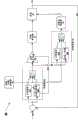
图1是主动悬挂系统的框图。Figure 1 is a block diagram of an active suspension system.
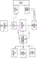
图2是用于主动悬挂系统的控制系统的框图。2 is a block diagram of a control system for an active suspension system.
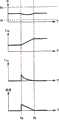
图3A和图3B描绘了作为对设备进行卸载和加载的结果的、位置、施加的力以及消耗的能量随时间的变化。3A and 3B depict changes in position, force applied, and energy expended over time as a result of unloading and loading the device.
图4是用于主动悬挂系统的控制系统的框图。4 is a block diagram of a control system for an active suspension system.
图5是虚拟加载-卸载检测器的框图。Figure 5 is a block diagram of a virtual load-unload detector.
具体实施方式Detailed ways
如图1所示,主动悬挂系统10包括电磁致动器12和力偏压消除器14,二者协作将设备16悬挂在平台(未示出)上。系统10还包括控制器20,其从各种感测器(包括加速度计22和24、位置感测器26和加载-卸载检测器28)接收信息,并控制致动器12和力偏压消除器14的操作,以相对于平台将设备16粗略地保持在同一平衡位置。在一个实现中,系统10在卡车驾驶室中使用,在该处,驾驶员的座位构成了设备,驾驶室的地面构成了平台。As shown in FIG. 1 , an
电磁致动器12经由控制器从电源30接收电功率。控制器20使用来自设备加速度计22、平台加速度计24和位置感测器的信息来生成控制信号40,该控制信号40用以调节放大器25向致动器供应的输出电流。The
电磁致动器能够非常快速地对平台垂直位置的突然、短暂改变做出响应。例如,如果系统10用于悬挂卡车座位,则致动器可以在卡车急剧颠簸地行驶时做出快速响应,以便将座位近似保持于其在驾驶室地面上的平衡位置。然而,归因于这一快速响应,致动器会在短时间内汲取较高的功率水平。由于系统的电源30(例如,卡车的交流发电机或电池)可能不能提供足够的功率,所以系统10提供有能量存储库32,诸如,电容组,以提供这种功率。Electromagnetic actuators are able to respond very quickly to sudden, brief changes in the platform's vertical position. For example, if the
力偏压消除器14是气动致动器,其连接至一个或多个流体渗出阀门21(其向力偏压消除器供应压缩的空气),并连接至一个或多个流体释放阀门23(其从力偏压消除器释放空气)。控制器20控制流体渗出阀门21和流体释放阀门23,以增大或减小力偏压消除器施加的向上的力。由于力偏压消除器是气动设备,其不会像电磁致动器那么快速地做出响应。由此,如在2004年10月29日提交的、名为“Active Suspending”的美国专利申请序列号10/978,105中所描述的(将其全部内容通过参考合并于此),力偏压消除器用于抵消设备的恒定负载(例如,坐在卡车座位上的驾驶员的重量和座位本身的重量)和平台的低频扰动(诸如,在卡车在较长起伏颠簸的地方行驶时引起的扰动),而电磁致动器对较高频扰动(诸如,卡车急剧颠簸地行驶)做出响应。The
归因于致动器(相对较快)和力偏压消除器(相对较慢)的不同响应时间,致动器将立即操作以抵消加载或卸载事件,直到力偏压消除器可以做出响应。例如,在卡车座位实现中,致动器会立即使用向上的力做出响应,以便补偿在驾驶员坐在其座位上时的驾驶员重量。致动器将继续施加这一向上的力,直到力偏压消除器可以做出响应并接手。类似地,当驾驶员从座位上起身时(这是卸载事件),致动器将施加向下的力来对抗力偏压消除器施加的向上的力。致动器将继续施加向下的力,直到力偏压消除器可以做出响应以便释放致动器。然而,致动器在施加这一向上或向下的力以抵消加载或卸载事件的影响时汲取了相当大的电流,使得其快速耗尽能量存储库(例如,图1中的能量存储库32)。如果致动器的能量存储库在力偏压消除器能够做出响应/接手之前便耗尽了,则致动器将失去功率,并且座位会突然下降(在加载事件时)或升高(在卸载事件时)。这产生了潜在的危险(或者至少是不舒服的)事件。Due to the different response times of the actuator (relatively fast) and the force bias eliminator (relatively slow), the actuator will operate immediately to counteract the loading or unloading event until the force bias eliminator can respond . For example, in a truck seat implementation, the actuator would respond instantly with an upward force in order to compensate for the driver's weight while the driver is sitting in his seat. The actuator will continue to apply this upward force until the force bias eliminator can respond and take over. Similarly, when the driver gets up from the seat (which is an unload event), the actuator will apply a downward force against the upward force exerted by the force bias eliminator. The actuator will continue to apply downward force until the force bias eliminator can respond to release the actuator. However, the actuator draws a considerable amount of current when applying this upward or downward force to counteract the effects of the loading or unloading event, causing it to quickly deplete the energy storage bank (e.g., energy storage bank 32 in FIG. 1 ). If the actuator's energy storage bank is depleted before the force bias eliminator can respond/take over, the actuator will lose power and the seat will suddenly drop (during a loading event) or raise (during when the event is unloaded). This creates a potentially dangerous (or at least uncomfortable) event.
为了缓解这一问题,系统10提供有加载-卸载检测器28,其向控制器20指示发生了加载或卸载事件。加载-卸载检测器可以实现为物理检测器,诸如,负载检测器、重量感测器或压力感测器,或者其可以用软件实现为虚拟检测器。在检测到加载或卸载事件时,控制器20将立即引起力偏压消除器14做出快速响应。另外,在包括图1中所示实现在内的一些实现中,控制器20还可以配置用于在加载事件或卸载事件期间减慢致动器的响应(与致动器正常响应时间相比)。由此,加载-卸载检测器28用作系统的“拉发线(trip-wire)”,其引起控制器立即做出响应,而不用等待其他感测器信号(例如,来自加速度计22或24或位置感测器26的信号)和/或控制器20可以从致动器和/或力偏压消除器接收的反馈控制信号(未示出)。To alleviate this problem, the
如果设备16的加载事件被加载-卸载检测器28检测到,则控制器20将立即完全打开所有流体渗出阀门,以引起流体(例如,压缩空气)快速填充力偏压消除器,直到其达到这样的点,在该处,其施加可抵消附加的负载所施加的向下的力的向上的力。另外,控制器20监测存储在能量存储库中的能量水平E,并随着能量存储库32逐渐耗尽而逐渐减小放电速率(例如,通过逐渐减小向致动器供应的电流量)。类似地,如果卸载事件被加载-卸载检测器28检测到,则控制器将完全打开所有的流体释放阀门,以将流体从力偏压消除器释放,以及由此消除在负载存在时其提供的向上的力。控制器20还可以随着能量存储库32逐渐耗尽而逐渐减小放电速率。If a loading event of the
在一些实现中,控制器可以并不直接测量存储在能量源中的能量。而是,控制器可以使用电源和/或能量存储库的特征模型来预测可用电能的水平和放电速率。应当注意,在一些实现中,力偏压消除器可以具有足够快的响应时间,使得不需要控制器减慢致动器的响应时间来保存能量。In some implementations, the controller may not directly measure the energy stored in the energy source. Instead, the controller can use a characteristic model of the power source and/or energy storage bank to predict the level of available electrical energy and the rate of discharge. It should be noted that in some implementations, the force bias eliminator may have a sufficiently fast response time such that the controller is not required to slow down the response time of the actuator to conserve energy.
流体渗出阀门和流体释放阀门优选地设计成使得它们允许在检测到加载或卸载事件时能够做出快速响应,而且能够被控制以准确地对在操作期间遇到的低频扰动做出响应。例如,在一些实现中,并行连接若干渗出阀门和/或释放阀门,其允许在加载或卸载事件期间的快速响应(例如,通过一次完全打开所有阀门),而且允许流体的精确注入或释放。备选地,使用单个渗出和/或释放阀门,其可以快速做出响应以传递大量流体,也可以被精确控制。The fluid seepage valve and fluid release valve are preferably designed such that they allow a quick response when a loading or unloading event is detected, yet can be controlled to respond accurately to low frequency disturbances encountered during operation. For example, in some implementations, several bleed valves and/or release valves are connected in parallel, which allows quick response during a loading or unloading event (eg, by fully opening all valves at once), but also allows precise injection or release of fluid. Alternatively, a single bleed and/or release valve is used, which can respond quickly to deliver large volumes of fluid, and can also be precisely controlled.
如图2所示,示出了用于控制电磁致动器50和力偏压消除器54的控制系统40。控制系统40包括控制致动器50操作的补偿器42和控制力偏压消除器54操作的控制逻辑44。补偿器42和控制逻辑44的每一个具有两个操作模式:正常操作模式55A、55B和加载/卸载操作模式56A、56B。加载/卸载检测器46将补偿器42和控制逻辑44在两个操作模式之间进行切换。如之前所示,加载/卸载检测器46可以实现为物理感测器或虚拟检测器(例如,图4和图5中所示虚拟加载/卸载检测器)。As shown in FIG. 2 , a
在正常操作中,补偿器42和控制逻辑44协作地悬挂设备16,使得可以符合第一预定系统性能标准。在一个实现中,补偿器42和控制逻辑44协作地悬挂设备16,以在将设备16经历的加速度最小化的同时维持预定平衡位置。预定平衡位置可以对应于致动器50的冲程的中点。2004年10月29日提交的、名为“Active Suspending”的美国专利申请序列号10/978,105中更详细地描述了在正常操作中对致动器和力偏压消除器的控制。In normal operation, compensator 42 and control logic 44 cooperatively suspend
在加载/卸载检测器检测到加载或卸载事件时,其引起补偿器42和控制逻辑44立即切换到加载/卸载模式56A、56B。在此模式中,补偿器接收信号(51),其指示能量存储中可用的电能,以及随着时间减小向致动器供应的电流水平,以便保存能量存储中的能量并延长致动器可以提供力的时间。同时,控制逻辑44引起力偏压消除器54快速地对加载/卸载事件做出响应,以释放致动器。一旦力偏压消除器做出响应以抵消加载/卸载事件(例如,在设备返回至其平衡位置附近并具有低于特定阈值的速率时),系统切换回其正常操作模式。When the load/unload detector detects a load or unload event, it causes the compensator 42 and control logic 44 to immediately switch to the load/unload
在一个实现中,当系统操作于加载/卸载模式中时,补偿器42和/或控制逻辑44悬挂设备16,使得可以符合第二预定系统性能标准。在一个示例中,PID控制器实现在加载/卸载模式中。In one implementation, when the system is operating in the load/unload mode, compensator 42 and/or control logic 44 suspends
图3A和图3B分别示出了在加载和卸载事件期间的系统(诸如图1和图2中所示)性能。如图3A的上部曲线图所示,当在时间Ta处发生加载事件时,设备16经历位置的些许变化(在向下方向)但未达到设备的垂直位移的下限(Pll)。如中间曲线图所示,控制器在时间Ta打开流体渗出阀门,以快速提升力偏压消除器的向上的弹簧力,使得其在时间Tb处已对加载事件做出完全响应。在此示例中,力偏压消除器的响应是线性的。随着力偏压消除器转变在时间Tb处抵消加载事件的向下的力,座位位置轻微抬高至位于其垂直位移的上限和下限(分别是pul和pll)之间的平衡位置。如第三曲线图所示,控制器控制致动器在时间Ta处利用向上的力做出快速响应,但是继而在力偏压消除器的响应时间上快速减小致动器施加的向上的力,使得致动器在时间Tb处恢复“休息”状态。控制器根据能量存储库(例如,图1的元件32)中可用的能量来减小致动器施加的向上的力。在此示例中,控制器监测可用的能量水平,并控制致动器使得致动器以这样的速率来线性地消耗能量,即,能量存储库将耗尽的时间与力偏压消除器做出响应(这在图3A的最下面曲线图中示出)的时间几乎同时。由此,随着电源的耗尽,致动器的力缓慢下降,而座位位置趋于平衡。在加载和卸载事件期间的致动器中的力不再是弹簧力与质量之间的区别,而是依赖于容量中能量(电压)的较小的区别。3A and 3B illustrate the performance of a system (such as that shown in FIGS. 1 and 2 ) during loading and unloading events, respectively. As shown in the upper graph of FIG. 3A , when a loading event occurs at time Ta,
类似地,如图3B最上面的曲线图所示,在时间TA处发生卸载事件时,设备经历位置的些许变化(在向上的方向)。与之前一样,这一位置变化并未接近设备垂直位移的上限(pul)。如中间曲线图所示,控制器在时间Ta处打开流体释放阀门,以便快速地减小力偏压消除器的向上的弹簧力,使得其在时间Tb处已对卸载事件做出完全响应。随着力偏压消除器转变在时间Tb处抵消卸载事件引起的向上的力,座位的位置轻微地下降至其垂直位移的上限和下限(分别是pul和pll)之间的平衡位置。如下面曲线图所示,控制器控制致动器利用向下的力在时间Ta处快速做出响应,但是继而在力偏压消除器的响应时间期间快速减小致动器施加的向下的力,使得致动器在时间Tb处恢复“休息”状态。与之前一样,控制器根据可用能量的量逐渐减小致动器施加的向下的力。如上所述,加载-卸载检测器可以实现为物理检测器,诸如设备表面上的压力开关,或者以软件实现为“虚拟”检测器。图4示出了虚拟加载-卸载检测器的示例。Similarly, as shown in the uppermost graph of Figure 3B, when an unload event occurs at time TA, the device experiences a slight change in position (in an upward direction). As before, this change in position does not approach the upper limit of vertical displacement of the device (pul ). As shown in the middle graph, the controller opens the fluid release valve at time Ta to rapidly reduce the upward spring force of the force bias eliminator so that it has fully responded to the unload event at time Tb. As the force bias eliminator transitions at time Tb to counteract the upward force induced by the unloading event, the position of the seat drops slightly to an equilibrium position between its upper and lower limits of vertical displacement (puul and pll , respectively). As shown in the graph below, the controller controls the actuator to respond rapidly at time Ta with a downward force, but then rapidly reduces the downward force applied by the actuator during the response time of the force bias eliminator. force, causing the actuator to return to the "rest" state at time Tb. As before, the controller gradually reduces the downward force applied by the actuator according to the amount of energy available. As mentioned above, the load-unload detector can be implemented as a physical detector, such as a pressure switch on the surface of the device, or in software as a "virtual" detector. Figure 4 shows an example of a virtual load-unload detector.
如图4所示,虚拟加载-卸载检测器60接收用以控制致动器的信号(信号73)和用以控制力偏压消除器的信号(信号71),信号中的一个或二者指示设备的当前位置(信号77)和加速度(信号79),以及在一些实现中,指示平台的加速度(信号81)。在一个实现中,虚拟加载-卸载检测器监测控制信号71、73以及设备68的当前位置77和加速度信号79中的一个或两个,以确定设备的当前垂直位置和/或任何当前垂直移动是否与设备模型预期的、响应于控制信号71、73的当前状态的垂直位置和/或垂直移动一致。换言之,虚拟加载-卸载检测器60例如查看设备68是未按照作为致动器66和力偏压消除器70正在操作的方式的结果所期待发生的那种方式垂直移动,还是处于垂直位置处。与鉴于致动器66和力偏压消除器70的当前操作的期待不一致的、设备68的垂直位置或垂直移动倾向于指示:除了致动器66和/或力偏压消除器70正通过控制信号71、73在设备66上施加的力之外的外力正作用于设备68上。As shown in Figure 4, virtual load-unload
这种不一致可能是由加载或卸载事件引起的或者不是由其引起的,并且虚拟加载-卸载检测器60尝试将由加载或卸载事件导致的引起这种不一致性的外力与出于其他原因引起的外力区分开。例如,在一些实施方式中,虚拟加载-卸载检测器60确定外力与座位移动具有相同方向还是相反方向。在看起来存在这种抵抗性的外力(例如,方向与座位移动相反,大小大于预定阈值)的情况下,虚拟加载-卸载检测器60可以假设发生了指示机械故障的摩擦力,而不是加载或卸载事件。在看起来存在与座位移动相同方向的外力(大小大于预定阈值)的情况下,虚拟加载-卸载检测器60可以推断发生了加载或卸载事件。This inconsistency may or may not be caused by a loading or unloading event, and the virtual load-unloading
当虚拟加载-卸载检测器60确定存在加载-卸载事件时,控制器将立即做出响应,以引起力偏压消除器抵消加载-卸载事件,并且在一些实施方式中,主动管理致动器汲取的功率,使得不会快速耗尽其能量源,从而允许致动器提供较长时段的力。When the virtual load-unload
在正常工作条件下,在致动器上作用的力扰动(例如,摩擦)在小范围内变化。然而,在加载/卸载的情况下,负载的改变表现出较大的力扰动,其方向涉及系统的移动方向。这一特征使得可以使用力扰动(其中位置信号作为事件标志)来非常快速地检测加载/卸载的发生。Under normal operating conditions, force disturbances (eg, friction) acting on the actuator vary within a small range. However, in the case of loading/unloading, the change of load exhibits a large force disturbance whose direction is related to the direction of movement of the system. This feature makes it possible to use force perturbations (where the position signal acts as an event marker) to detect the occurrence of loading/unloading very quickly.
如图5所示,虚拟加载/卸载检测器80的另一示例包括设备模型82和自适应估计算法86。设备模型82将命令化的力和地面加速度作为输入,以计算预测的悬挂位置。在本发明的上下文中,悬挂位置被定义为设备与地面之间的相对位置。这一预测悬挂位置继而与测量的悬挂位置进行比较以生成预测误差。预测误差继而与设备和马达加速度一起馈送给自适应估计算法86,以估计引起预测误差的力命令扰动。估计的力命令扰动与测量的悬挂位置和速度一起被传递给检测逻辑92,在该处,针对一套扰动隔离标准来检查信号的边界和符号。在一个实现中,检测逻辑92检测估计的力命令是否具有大于与测量的设备速度在同一方向的预定阈值的大小,检测逻辑92将指示发生了加载或卸载事件。Another example of a virtual load/unload
已经描述了本发明的多个实施方式。然而,应当理解,在不脱离本发明精神和范围的前提下,可以做出各种修改。例如,尽管上文示例主要使用与可变气垫一起使用的电磁致动器,但是系统可以利用具有不同响应时间的任何两种致动器来实现对较高频率事件做出快速响应的“快速”致动器和对DC或低频事件做出响应的“低速”致动器(或力偏压消除器)。类似地,尽管附图中将某些元件示出为单个框(例如,控制器),但是实际系统可以使用单独组件来实现这些元件。例如,图1中所示系统控制器可以实现为使用单独处理器的两个控制器(例如,一个控制致动器,第二个控制力偏压消除器)。最后,上述给出的示例很大程度上关注于作为卡车座位的设备。然而,其他形式的设备落入本公开的范围,诸如,客车的座位、载重卡车的地面、军用车辆的武器平台或者海船的整个房间。因此,其他实施方式也落入以下权利要求的范围内。A number of embodiments of the invention have been described. However, it should be understood that various modifications may be made without departing from the spirit and scope of the invention. For example, although the examples above primarily use electromagnetic actuators used with variable air cushions, the system could utilize any two actuators with different response times to achieve "fast" responses to higher frequency events. Actuators and "low speed" actuators (or force bias eliminators) that respond to DC or low frequency events. Similarly, although the figures show some elements as a single block (eg, a controller), an actual system may implement these elements using separate components. For example, the system controller shown in FIG. 1 could be implemented as two controllers using separate processors (eg, one controlling the actuator and the second controlling the force bias eliminator). Finally, the examples given above have largely focused on the device as a truck seat. However, other forms of equipment fall within the scope of this disclosure, such as seats in a passenger car, the floor of a truck, a weapons platform on a military vehicle, or an entire room on a marine vessel. Accordingly, other implementations are within the scope of the following claims.
Claims (12)
Applications Claiming Priority (3)
| Application Number | Priority Date | Filing Date | Title |
|---|---|---|---|
| US12/059,336 | 2008-03-31 | ||
| US12/059,336US8112198B2 (en) | 2008-03-31 | 2008-03-31 | Loading and unloading stabilization in an active suspension system |
| PCT/US2009/033654WO2009123792A1 (en) | 2008-03-31 | 2009-02-10 | Loading and unloading stabilization in an active suspension system |
Publications (2)
| Publication Number | Publication Date |
|---|---|
| CN101983140A CN101983140A (en) | 2011-03-02 |
| CN101983140Btrue CN101983140B (en) | 2013-03-20 |
Family
ID=40577755
Family Applications (1)
| Application Number | Title | Priority Date | Filing Date |
|---|---|---|---|
| CN200980112213.0AActiveCN101983140B (en) | 2008-03-31 | 2009-02-10 | Active suspension system and control method thereof |
Country Status (5)
| Country | Link |
|---|---|
| US (1) | US8112198B2 (en) |
| EP (1) | EP2274180B1 (en) |
| JP (1) | JP5341981B2 (en) |
| CN (1) | CN101983140B (en) |
| WO (1) | WO2009123792A1 (en) |
Families Citing this family (36)
| Publication number | Priority date | Publication date | Assignee | Title |
|---|---|---|---|---|
| US9241850B2 (en) | 2011-09-02 | 2016-01-26 | Ferno-Washington, Inc. | Litter support assembly for medical care units having a shock load absorber and methods of their use |
| US8725351B1 (en) | 2012-10-31 | 2014-05-13 | Bose Corporation | Active suspension system |
| US8814468B1 (en) | 2013-02-12 | 2014-08-26 | Disney Enterprises, Inc. | Dynamic roll/pitch stabilizer for use during loading and unloading of small passenger boats |
| EP3626485B1 (en) | 2013-03-15 | 2024-05-29 | ClearMotion, Inc. | Active vehicle suspension improvements |
| US9702349B2 (en) | 2013-03-15 | 2017-07-11 | ClearMotion, Inc. | Active vehicle suspension system |
| DE102013110370B4 (en)* | 2013-06-04 | 2014-12-11 | Grammer Ag | vehicle seat |
| DE102013110924B4 (en) | 2013-10-01 | 2018-02-08 | Grammer Ag | Vehicle with force-controlled damper with control valve |
| DE102013110923B4 (en) | 2013-10-01 | 2019-07-04 | Grammer Ag | Vehicle seat or vehicle cabin with a suspension device and utility vehicle |
| DE102013110920B4 (en) | 2013-10-01 | 2018-08-16 | Grammer Ag | Vehicle seat with force-controlled damper (2-pipe damper) |
| DE102013021561B4 (en) | 2013-12-16 | 2020-09-03 | Grammer Ag | Vehicle seat with a horizontally movable seat surface to accommodate a person |
| DE102014201010A1 (en)* | 2014-01-21 | 2015-07-23 | Airbus Operations Gmbh | System for supplying energy to an electric seat device in an aircraft or spacecraft |
| CN104816738A (en)* | 2014-10-23 | 2015-08-05 | 华东交通大学 | Method and apparatus for multi-velocity control of high-speed train electromagnetic active levitation system |
| US9643467B2 (en)* | 2014-11-10 | 2017-05-09 | Bose Corporation | Variable tracking active suspension system |
| US9440508B2 (en) | 2014-11-25 | 2016-09-13 | Seth M. LACHICA | Active vehicle suspension system and method for managing drive energy |
| US10300760B1 (en) | 2015-03-18 | 2019-05-28 | Apple Inc. | Fully-actuated suspension system |
| CN104950667A (en)* | 2015-03-25 | 2015-09-30 | 华东交通大学 | Multi-rate prediction control method applied to train active suspension system |
| US9846425B2 (en) | 2015-03-31 | 2017-12-19 | Bose Corporation | Retrieving pre-determined controller parameters to isolate vibrations in an authorized payload |
| CN117207734A (en) | 2015-12-24 | 2023-12-12 | 动态清晰公司 | Integrated multi-actuator electro-hydraulic unit |
| US10814690B1 (en) | 2017-04-18 | 2020-10-27 | Apple Inc. | Active suspension system with energy storage device |
| JP2020518514A (en) | 2017-05-08 | 2020-06-25 | アップル インコーポレイテッドApple Inc. | Active suspension system |
| US10899340B1 (en) | 2017-06-21 | 2021-01-26 | Apple Inc. | Vehicle with automated subsystems |
| DE102017212225B4 (en) | 2017-07-18 | 2021-07-08 | Ford Global Technologies, Llc | Estimation of loads acting on a rear axle of a motor vehicle |
| US11173766B1 (en) | 2017-09-07 | 2021-11-16 | Apple Inc. | Suspension system with locking structure |
| US10906370B1 (en) | 2017-09-15 | 2021-02-02 | Apple Inc. | Active suspension system |
| US11124035B1 (en) | 2017-09-25 | 2021-09-21 | Apple Inc. | Multi-stage active suspension actuator |
| US10960723B1 (en) | 2017-09-26 | 2021-03-30 | Apple Inc. | Wheel-mounted suspension actuators |
| US11285773B1 (en) | 2018-09-12 | 2022-03-29 | Apple Inc. | Control system |
| US11634167B1 (en) | 2018-09-14 | 2023-04-25 | Apple Inc. | Transmitting axial and rotational movement to a hub |
| US11345209B1 (en) | 2019-06-03 | 2022-05-31 | Apple Inc. | Suspension systems |
| US11938922B1 (en) | 2019-09-23 | 2024-03-26 | Apple Inc. | Motion control system |
| US11179991B1 (en) | 2019-09-23 | 2021-11-23 | Apple Inc. | Suspension systems |
| US11707961B1 (en) | 2020-04-28 | 2023-07-25 | Apple Inc. | Actuator with reinforcing structure for torsion resistance |
| US11828339B1 (en) | 2020-07-07 | 2023-11-28 | Apple Inc. | Vibration control system |
| US12017498B2 (en) | 2021-06-07 | 2024-06-25 | Apple Inc. | Mass damper system |
| US12251973B2 (en) | 2022-06-10 | 2025-03-18 | Apple Inc. | Vibration absorber |
| US12168375B1 (en) | 2023-01-26 | 2024-12-17 | Apple Inc. | Motion control system |
Citations (3)
| Publication number | Priority date | Publication date | Assignee | Title |
|---|---|---|---|---|
| GB2138102A (en)* | 1983-04-07 | 1984-10-17 | Isringhausen Geb | Control of pneumatic spring supporting vehicle seat |
| US4589620A (en)* | 1983-12-20 | 1986-05-20 | Tachikawa Spring Co., Ltd. | Seat with an air suspension |
| CN1537747A (en)* | 2003-04-14 | 2004-10-20 | 格拉默股份公司 | Device and method for suspension of vehicle seat |
Family Cites Families (13)
| Publication number | Priority date | Publication date | Assignee | Title |
|---|---|---|---|---|
| US4664218A (en)* | 1984-10-05 | 1987-05-12 | National Emstop, Inc. | Safety back-up system for vehicles |
| US5582385A (en)* | 1995-04-27 | 1996-12-10 | The Lubrizol Corporation | Method for controlling motion using an adjustable damper |
| US5975508A (en)* | 1995-09-06 | 1999-11-02 | Applied Power Inc. | Active vehicle seat suspension system |
| US5908456A (en)* | 1997-08-18 | 1999-06-01 | Caterpillar Inc. | Method for controlling a seat suspension system |
| US6311110B1 (en)* | 1999-06-17 | 2001-10-30 | Lord Corporation | Adaptive off-state control method |
| EP1278654B1 (en)* | 2000-05-02 | 2005-10-12 | Lord Corporation | Method for limiting endstop collisions in semi-active seat suspension systems |
| US6886650B2 (en)* | 2002-11-13 | 2005-05-03 | Deere & Company | Active seat suspension control system |
| US7983813B2 (en) | 2004-10-29 | 2011-07-19 | Bose Corporation | Active suspending |
| US8095268B2 (en) | 2004-10-29 | 2012-01-10 | Bose Corporation | Active suspending |
| US7921973B2 (en)* | 2006-05-31 | 2011-04-12 | Techno-Sciences, Inc. | Adaptive energy absorption system for a vehicle seat |
| US7878312B2 (en)* | 2006-05-31 | 2011-02-01 | University Of Maryland | Adaptive energy absorption system for a vehicle seat |
| US8311705B2 (en)* | 2007-02-02 | 2012-11-13 | Techno-Sciences, Inc. | Constant force control methodology for shock absorption |
| US20090218867A1 (en)* | 2008-02-28 | 2009-09-03 | Bose Corporation | Plant Suspension System with Weight Compensation |
- 2008
- 2008-03-31USUS12/059,336patent/US8112198B2/enactiveActive
- 2009
- 2009-02-10JPJP2011503000Apatent/JP5341981B2/enactiveActive
- 2009-02-10WOPCT/US2009/033654patent/WO2009123792A1/enactiveApplication Filing
- 2009-02-10CNCN200980112213.0Apatent/CN101983140B/enactiveActive
- 2009-02-10EPEP09727989.7Apatent/EP2274180B1/enactiveActive
Patent Citations (3)
| Publication number | Priority date | Publication date | Assignee | Title |
|---|---|---|---|---|
| GB2138102A (en)* | 1983-04-07 | 1984-10-17 | Isringhausen Geb | Control of pneumatic spring supporting vehicle seat |
| US4589620A (en)* | 1983-12-20 | 1986-05-20 | Tachikawa Spring Co., Ltd. | Seat with an air suspension |
| CN1537747A (en)* | 2003-04-14 | 2004-10-20 | 格拉默股份公司 | Device and method for suspension of vehicle seat |
Also Published As
| Publication number | Publication date |
|---|---|
| EP2274180B1 (en) | 2016-01-13 |
| CN101983140A (en) | 2011-03-02 |
| HK1153176A1 (en) | 2012-03-23 |
| JP5341981B2 (en) | 2013-11-13 |
| JP2011516333A (en) | 2011-05-26 |
| EP2274180A1 (en) | 2011-01-19 |
| US20090248246A1 (en) | 2009-10-01 |
| US8112198B2 (en) | 2012-02-07 |
| WO2009123792A1 (en) | 2009-10-08 |
Similar Documents
| Publication | Publication Date | Title |
|---|---|---|
| CN101983140B (en) | Active suspension system and control method thereof | |
| CN102649406B (en) | Apparatus for controlling active suspending device of vehicles | |
| CN104870858B (en) | Active suspension | |
| CN101067435B (en) | active suspension | |
| ES2675740T3 (en) | Brake torque control | |
| US9592715B2 (en) | Method and apparatus for active dynamic trimming of suspension damping including negative stiffness | |
| JP2006125633A5 (en) | ||
| WO2003008213A1 (en) | Controlled equilibrium device with displacement dependent spring rates and integral damping | |
| JP2021134022A (en) | Vibration prevention system for cargo handling vehicle and cargo handling vehicle | |
| HK1153176B (en) | Loading and unloading stabilization in an active suspension system | |
| JP2009019674A (en) | Vibration control device | |
| HK1088650B (en) | Active suspending | |
| HK1171992B (en) | An apparatus for controlling an actively-suspended plant in a vehicle | |
| JP2024112429A (en) | Vehicle control device | |
| HK1140730B (en) | Active suspending | |
| JP2009154774A (en) | Vibration control device |
Legal Events
| Date | Code | Title | Description |
|---|---|---|---|
| C06 | Publication | ||
| PB01 | Publication | ||
| C10 | Entry into substantive examination | ||
| SE01 | Entry into force of request for substantive examination | ||
| C14 | Grant of patent or utility model | ||
| GR01 | Patent grant |