CN101981776A - Systems and methods for ground fault detection and interruption - Google Patents
Systems and methods for ground fault detection and interruptionDownload PDFInfo
- Publication number
- CN101981776A CN101981776ACN2009801108006ACN200980110800ACN101981776ACN 101981776 ACN101981776 ACN 101981776ACN 2009801108006 ACN2009801108006 ACN 2009801108006ACN 200980110800 ACN200980110800 ACN 200980110800ACN 101981776 ACN101981776 ACN 101981776A
- Authority
- CN
- China
- Prior art keywords
- signal
- ground fault
- array
- energy conversion
- ground
- Prior art date
- Legal status (The legal status is an assumption and is not a legal conclusion. Google has not performed a legal analysis and makes no representation as to the accuracy of the status listed.)
- Granted
Links
- 238000000034methodMethods0.000titleclaimsabstractdescription24
- 238000001514detection methodMethods0.000titleclaimsabstractdescription22
- 238000006243chemical reactionMethods0.000claimsabstractdescription45
- 230000007935neutral effectEffects0.000claimsdescription16
- 238000012545processingMethods0.000claimsdescription12
- 238000003491arrayMethods0.000claimsdescription5
- 230000003071parasitic effectEffects0.000claimsdescription5
- 239000002131composite materialSubstances0.000claimsdescription3
- 238000010586diagramMethods0.000description11
- 230000009471actionEffects0.000description3
- 230000008901benefitEffects0.000description3
- 239000004020conductorSubstances0.000description2
- 238000010276constructionMethods0.000description2
- 231100001261hazardousToxicity0.000description2
- 230000004044responseEffects0.000description2
- 238000012360testing methodMethods0.000description2
- 238000013461designMethods0.000description1
- 238000002955isolationMethods0.000description1
- 238000012986modificationMethods0.000description1
- 230000004048modificationEffects0.000description1
- 230000005404monopoleEffects0.000description1
- 230000009467reductionEffects0.000description1
- 238000006467substitution reactionMethods0.000description1
Images


Classifications
- H—ELECTRICITY
- H10—SEMICONDUCTOR DEVICES; ELECTRIC SOLID-STATE DEVICES NOT OTHERWISE PROVIDED FOR
- H10F—INORGANIC SEMICONDUCTOR DEVICES SENSITIVE TO INFRARED RADIATION, LIGHT, ELECTROMAGNETIC RADIATION OF SHORTER WAVELENGTH OR CORPUSCULAR RADIATION
- H10F77/00—Constructional details of devices covered by this subclass
- H10F77/95—Circuit arrangements
- H10F77/953—Circuit arrangements for devices having potential barriers
- H10F77/955—Circuit arrangements for devices having potential barriers for photovoltaic devices
- G—PHYSICS
- G01—MEASURING; TESTING
- G01R—MEASURING ELECTRIC VARIABLES; MEASURING MAGNETIC VARIABLES
- G01R31/00—Arrangements for testing electric properties; Arrangements for locating electric faults; Arrangements for electrical testing characterised by what is being tested not provided for elsewhere
- G01R31/327—Testing of circuit interrupters, switches or circuit-breakers
- G—PHYSICS
- G01—MEASURING; TESTING
- G01R—MEASURING ELECTRIC VARIABLES; MEASURING MAGNETIC VARIABLES
- G01R31/00—Arrangements for testing electric properties; Arrangements for locating electric faults; Arrangements for electrical testing characterised by what is being tested not provided for elsewhere
- G01R31/50—Testing of electric apparatus, lines, cables or components for short-circuits, continuity, leakage current or incorrect line connections
- G01R31/52—Testing for short-circuits, leakage current or ground faults
- H—ELECTRICITY
- H02—GENERATION; CONVERSION OR DISTRIBUTION OF ELECTRIC POWER
- H02H—EMERGENCY PROTECTIVE CIRCUIT ARRANGEMENTS
- H02H3/00—Emergency protective circuit arrangements for automatic disconnection directly responsive to an undesired change from normal electric working condition with or without subsequent reconnection ; integrated protection
- H02H3/26—Emergency protective circuit arrangements for automatic disconnection directly responsive to an undesired change from normal electric working condition with or without subsequent reconnection ; integrated protection responsive to difference between voltages or between currents; responsive to phase angle between voltages or between currents
- H02H3/32—Emergency protective circuit arrangements for automatic disconnection directly responsive to an undesired change from normal electric working condition with or without subsequent reconnection ; integrated protection responsive to difference between voltages or between currents; responsive to phase angle between voltages or between currents involving comparison of the voltage or current values at corresponding points in different conductors of a single system, e.g. of currents in go and return conductors
- H02H3/33—Emergency protective circuit arrangements for automatic disconnection directly responsive to an undesired change from normal electric working condition with or without subsequent reconnection ; integrated protection responsive to difference between voltages or between currents; responsive to phase angle between voltages or between currents involving comparison of the voltage or current values at corresponding points in different conductors of a single system, e.g. of currents in go and return conductors using summation current transformers
- H02H3/334—Emergency protective circuit arrangements for automatic disconnection directly responsive to an undesired change from normal electric working condition with or without subsequent reconnection ; integrated protection responsive to difference between voltages or between currents; responsive to phase angle between voltages or between currents involving comparison of the voltage or current values at corresponding points in different conductors of a single system, e.g. of currents in go and return conductors using summation current transformers with means to produce an artificial imbalance for other protection or monitoring reasons or remote control
- H02H3/335—Emergency protective circuit arrangements for automatic disconnection directly responsive to an undesired change from normal electric working condition with or without subsequent reconnection ; integrated protection responsive to difference between voltages or between currents; responsive to phase angle between voltages or between currents involving comparison of the voltage or current values at corresponding points in different conductors of a single system, e.g. of currents in go and return conductors using summation current transformers with means to produce an artificial imbalance for other protection or monitoring reasons or remote control the main function being self testing of the device
- H—ELECTRICITY
- H01—ELECTRIC ELEMENTS
- H01H—ELECTRIC SWITCHES; RELAYS; SELECTORS; EMERGENCY PROTECTIVE DEVICES
- H01H83/00—Protective switches, e.g. circuit-breaking switches, or protective relays operated by abnormal electrical conditions otherwise than solely by excess current
- H01H83/02—Protective switches, e.g. circuit-breaking switches, or protective relays operated by abnormal electrical conditions otherwise than solely by excess current operated by earth fault currents
- H01H83/04—Protective switches, e.g. circuit-breaking switches, or protective relays operated by abnormal electrical conditions otherwise than solely by excess current operated by earth fault currents with testing means for indicating the ability of the switch or relay to function properly
- H—ELECTRICITY
- H02—GENERATION; CONVERSION OR DISTRIBUTION OF ELECTRIC POWER
- H02H—EMERGENCY PROTECTIVE CIRCUIT ARRANGEMENTS
- H02H7/00—Emergency protective circuit arrangements specially adapted for specific types of electric machines or apparatus or for sectionalised protection of cable or line systems, and effecting automatic switching in the event of an undesired change from normal working conditions
- H02H7/10—Emergency protective circuit arrangements specially adapted for specific types of electric machines or apparatus or for sectionalised protection of cable or line systems, and effecting automatic switching in the event of an undesired change from normal working conditions for converters; for rectifiers
- H02H7/12—Emergency protective circuit arrangements specially adapted for specific types of electric machines or apparatus or for sectionalised protection of cable or line systems, and effecting automatic switching in the event of an undesired change from normal working conditions for converters; for rectifiers for static converters or rectifiers
- H02H7/122—Emergency protective circuit arrangements specially adapted for specific types of electric machines or apparatus or for sectionalised protection of cable or line systems, and effecting automatic switching in the event of an undesired change from normal working conditions for converters; for rectifiers for static converters or rectifiers for inverters, i.e. DC/AC converters
- H02H7/1222—Emergency protective circuit arrangements specially adapted for specific types of electric machines or apparatus or for sectionalised protection of cable or line systems, and effecting automatic switching in the event of an undesired change from normal working conditions for converters; for rectifiers for static converters or rectifiers for inverters, i.e. DC/AC converters responsive to abnormalities in the input circuit, e.g. transients in the DC input
- H—ELECTRICITY
- H02—GENERATION; CONVERSION OR DISTRIBUTION OF ELECTRIC POWER
- H02H—EMERGENCY PROTECTIVE CIRCUIT ARRANGEMENTS
- H02H7/00—Emergency protective circuit arrangements specially adapted for specific types of electric machines or apparatus or for sectionalised protection of cable or line systems, and effecting automatic switching in the event of an undesired change from normal working conditions
- H02H7/20—Emergency protective circuit arrangements specially adapted for specific types of electric machines or apparatus or for sectionalised protection of cable or line systems, and effecting automatic switching in the event of an undesired change from normal working conditions for electronic equipment
- Y—GENERAL TAGGING OF NEW TECHNOLOGICAL DEVELOPMENTS; GENERAL TAGGING OF CROSS-SECTIONAL TECHNOLOGIES SPANNING OVER SEVERAL SECTIONS OF THE IPC; TECHNICAL SUBJECTS COVERED BY FORMER USPC CROSS-REFERENCE ART COLLECTIONS [XRACs] AND DIGESTS
- Y02—TECHNOLOGIES OR APPLICATIONS FOR MITIGATION OR ADAPTATION AGAINST CLIMATE CHANGE
- Y02E—REDUCTION OF GREENHOUSE GAS [GHG] EMISSIONS, RELATED TO ENERGY GENERATION, TRANSMISSION OR DISTRIBUTION
- Y02E10/00—Energy generation through renewable energy sources
- Y02E10/50—Photovoltaic [PV] energy
Landscapes
- Physics & Mathematics (AREA)
- General Physics & Mathematics (AREA)
- Engineering & Computer Science (AREA)
- Power Engineering (AREA)
- Photovoltaic Devices (AREA)
- Inverter Devices (AREA)
- Emergency Protection Circuit Devices (AREA)
Abstract
Description
Translated fromChinese技术领域technical field
本发明总体涉及用于将太阳能转换为电能的设备和方法,并且更具体地涉及用于可靠地探测不安全接地故障状况和在探测到不安全接地故障状况时中断该能量转换系统的操作的设备和方法。The present invention relates generally to apparatus and methods for converting solar energy to electrical energy, and more particularly to apparatus for reliably detecting an unsafe ground fault condition and interrupting operation of the energy conversion system when an unsafe ground fault condition is detected and methods.
背景技术Background technique
使用光伏(PV)系统将光能转变为电能已为人所知很长一段时间了,并且该光伏能量转换系统越来越多地实施于居住、商业和工业应用中。迅速探测不期望的到地的DC电流的分流,也称作接地故障,对于实施该系统来说是强制性的,因为接地故障潜在地存在危险状况,包括火灾危险。因此,为安全原因,光伏能量转换系统必需迅速探测接地故障状况并在合适的时候自动中断操作。The use of photovoltaic (PV) systems to convert light energy into electrical energy has been known for a long time, and such photovoltaic energy conversion systems are increasingly being implemented in residential, commercial and industrial applications. Prompt detection of undesired shunts of DC current to ground, also known as ground faults, is mandatory for implementing the system because ground faults potentially present hazardous conditions, including fire hazards. Therefore, for safety reasons, photovoltaic energy conversion systems must quickly detect ground fault conditions and automatically interrupt operations when appropriate.
除其它部件外,光伏系统典型地包括生成DC功率的光伏阵列和将DC功率转换为AC功率(例如单向或三相功率)的逆变器。在该系统中,典型地采用接地故障探测器和中断器(GFDI)来探测在PV阵列和地之间流动的DC电流。接地故障探测器和中断器中使用的一些部件不能被证明是高统一性(integrity)部件,这意味着用于接地故障探测器和中断器中的这些部件的可靠性不能保证在可接受的水平。因为接地故障探测器和中断器对于PV能量转换系统的安全操作通常很关键,所以必需采取措施来确保接地故障探测器和中断器在所有时间都正确操作。因此,需要设备和方法来连续确保接地故障探测器和中断器正确操作。Photovoltaic systems typically include, among other components, a photovoltaic array that generates DC power and an inverter that converts the DC power to AC power (eg, unidirectional or three-phase power). In this system, a Ground Fault Detector and Interrupter (GFDI) is typically employed to detect the DC current flowing between the PV array and ground. Some components used in ground fault detectors and interrupters cannot be certified as high integrity components, which means that the reliability of these components used in ground fault detectors and interrupters cannot be guaranteed at an acceptable level. Because ground fault detectors and interrupters are often critical to the safe operation of PV energy conversion systems, steps must be taken to ensure that ground fault detectors and interrupters are operating correctly at all times. Accordingly, there is a need for apparatus and methods to continuously ensure proper operation of ground fault detectors and interrupters.
发明内容Contents of the invention
以下总括图示中所示的本发明的范例实施例。在具体实施方式部分更充分地描述了这些和其它实施例。然而,应当理解,其不是意在将本发明限制于发明内容部分或具体实施方式部分中描述的形式。本领域技术人员能够认识到存在落入如权利要求所表述的本发明的精神和范围内的许多变形、等同和替代结构。Exemplary embodiments of the invention shown in the drawings are summarized below. These and other embodiments are described more fully in the Detailed Description section. It should be understood, however, that there is no intention to limit the invention to the forms described in this Summary or Detailed Description. Those skilled in the art will recognize that there are many variations, equivalents and alternative constructions that fall within the spirit and scope of the invention as expressed by the claims.
在一个实施例中,本发明的特征在于一种光伏能量转换系统,包括适于耦接至光伏阵列的第一和第二干线的第一和第二输入端。在此实施例中,逆变器配置为将来自光伏阵列的DC功率转换为AC功率。接地故障探测器和中断器耦接至第一和第二干线以及逆变器,其配置为探测PV阵列中的接地故障状况并在一旦探测到该状况时将PV阵列与光伏能量转换系统的其余部分去耦接。已知信号(例如具有可识别的签名的信号)耦接至接地故障探测器和中断器的输入端,然后在接地故障探测器和中断器的输出端被感测。如果在接地故障探测器和中断器的输出端未感测到已知信号,则表明接地故障探测器和中断器操作不正常,且PV阵列将会被与PV能量转换系统中的其余部件去耦接,由此中断操作。In one embodiment, the invention features a photovoltaic energy conversion system including first and second inputs adapted to be coupled to first and second rails of a photovoltaic array. In this embodiment, the inverter is configured to convert DC power from the photovoltaic array to AC power. A ground fault detector and interrupter coupled to the first and second mains and the inverter is configured to detect a ground fault condition in the PV array and connect the PV array to the rest of the photovoltaic energy conversion system upon detection of the condition. Partially decoupled. A known signal (eg, a signal with an identifiable signature) is coupled to the input of the ground fault detector and interrupter and then sensed at the output of the ground fault detector and interrupter. If no known signal is sensed at the output of the ground fault detector and interrupter, the ground fault detector and interrupter are not operating properly and the PV array will be decoupled from the rest of the PV energy conversion system connected, thereby interrupting the operation.
在另一实施例中,发明的特征在于确保接地故障探测器和中断器正常操作的方法。此实施例中的发明包括:将已知信号引入到接地故障探测器和中断器的输入端中;感测在接地故障探测器和中断器的输出端是否存在已知信号;以及依赖于在接地故障探测器和中断器的输出端是否存在已知信号来进行分支。如果存在已知信号,则滤除已知信号,并将滤波的信号传输至逆变器,但如果不存在已知信号,则将PV阵列与PV能量转换系统中的其余部件去耦接,并发出接地故障探测器和中断器操作不正常的警报。In another embodiment, the invention features a method of ensuring proper operation of a ground fault detector and interrupter. The invention in this embodiment includes: introducing a known signal into the input of the ground fault detector and interrupter; sensing the presence of the known signal at the output of the ground fault detector and interrupter; The presence of a known signal at the output of fault detectors and interrupters to branch. If a known signal is present, the known signal is filtered out and the filtered signal is passed to the inverter, but if the known signal is not present, the PV array is decoupled from the rest of the components in the PV energy conversion system and Provides an alarm for improper operation of ground fault detectors and interrupters.
在另一实施例中,本发明的特征在于在探测到需要中断系统的接地故障状况时,将双极光伏阵列与光伏能量转换系统的其余部分安全并有效地去耦接的方法。In another embodiment, the invention features a method of safely and efficiently decoupling a bipolar photovoltaic array from the rest of a photovoltaic energy conversion system upon detection of a ground fault condition requiring interruption of the system.
如先前所述,上述实施例和实施仅用于示例目的。本领域技术人员根据以下描述和权利要求,可以容易地认识到本发明的许多其它实施例、实施、和细节。As previously stated, the above-described embodiments and implementations are for illustration purposes only. Many other embodiments, implementations, and details of the invention will be readily apparent to those skilled in the art from the following description and claims.
附图说明Description of drawings
结合附图并参照以下具体实施方式和所附的权利要求,本发明的各种目的和优点以及更完全的认识是明显的并且更容易被接受,其中:Various objects and advantages and a fuller appreciation of the present invention will become apparent and more readily appreciated by reference to the following detailed description and appended claims, taken in conjunction with the accompanying drawings, in which:
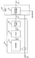
图1是描绘包括接地故障探测器和中断器的光伏能量转换系统的范例实施例的框图;1 is a block diagram depicting an example embodiment of a photovoltaic energy conversion system including a ground fault detector and an interrupter;
图2是描绘参照图1描述的接地故障探测器和中断器的范例实施例的框图;FIG. 2 is a block diagram depicting an example embodiment of the ground fault detector and interrupter described with reference to FIG. 1;
图3是描绘参照图1描述的接地故障探测器和中断器的另一范例实施例的框图;FIG. 3 is a block diagram depicting another example embodiment of the ground fault detector and interrupter described with reference to FIG. 1;
图4是描绘参照图1描述的接地故障探测器和中断器的另一范例实施例的框图;FIG. 4 is a block diagram depicting another example embodiment of the ground fault detector and interrupter described with reference to FIG. 1;
图5是描绘参照图1描述的接地故障探测器和中断器的另一范例实施例的框图;FIG. 5 is a block diagram depicting another example embodiment of the ground fault detector and interrupter described with reference to FIG. 1;
图6是描绘可以结合参照图1-5讨论的实施例来实现的范例方法的流程图;Figure 6 is a flowchart depicting an example method that may be implemented in conjunction with the embodiments discussed with reference to Figures 1-5;
图7是描绘参照图1描述的系统的部分的范例实施例的图示;FIG. 7 is a diagram depicting an example embodiment of a portion of the system described with reference to FIG. 1;
图8是描绘可以结合参照图1-7讨论的实施例来实现的范例方法的流程图。8 is a flowchart depicting an example method that may be implemented in conjunction with the embodiments discussed with reference to FIGS. 1-7.
具体实施方式Detailed ways
现在参照附图,其中,遍及数个视图,相似或类似的元件指定有相同或对应的参考数字,并且特别参照图1,所示的为描绘包括耦接至逆变器106的光伏阵列102的光伏功率转换系统100的框图。接地故障探测器和中断器104耦接于光伏阵列102和逆变器106之间。导线108将光伏阵列102耦接至逆变器106,接地故障探测器和中断器104耦接(例如感应耦接)至导线108。如所示,接地故障探测器和中断器104包括诊断部分114,且接地故障探测器和中断器104经由接地故障信号线110耦接至断开模块112。Referring now to the drawings, wherein like or similar elements have been designated with like or corresponding reference numerals throughout the several views, and with particular reference to FIG. Block diagram of photovoltaic
应当认识到,图1中描绘的部件的示例布置是逻辑上的,而不意味着实际的硬件图;从而,在实际实施中,部件能够进行组合或进一步被拆分。例如,接地故障探测器104可以由也用于逆变器106内的硬件和/或软件实现。且在一些实施中,断开模块112可以与光伏阵列102空间上分离。It should be appreciated that the example arrangement of components depicted in FIG. 1 is logical and does not imply an actual hardware diagram; thus, components can be combined or further divided in actual implementations. For example,
通常,光伏阵列102将太阳能转换为DC电流,DC电流被逆变器106转换为AC功率(例如,单相或三相功率)。光伏阵列102可以是单极或双极阵列。接地故障探测器和中断器104探测不安全接地故障状况并迅速动作以停止DC电流从阵列102至地的不安全流动。在许多实施例中,例如,接地故障探测器和中断器104感测接地故障并发送接地故障信号110至断开模块112以隔离阵列102(例如与地和逆变器106隔离)。Typically,
诊断部分114配置为测试接地故障探测器和中断器104是否在正常操作(例如正操作以探测接地故障),并且如果接地故障探测器和中断器104不在正常操作,则接地故障诊断部分114向断开模块112发送接地故障信号110以使阵列102离线。The
下面参照图2,所示的为参照图1描述的系统100的接地故障探测器和中断器104的范例实施例的框图图示。如所示,图2中描绘的接地故障探测器和中断器204中,来自光伏阵列(例如光伏阵列102)的输入线208耦接至DC电流变换器212。虽然为了示例方便,框图中将输入线208描绘为单个线,但是本领域技术人员容易理解,两个导线耦接至DC电流变换器212。在采用单极PV阵列102的PV能量转换系统100中,两个输入线208对应于至PV阵列102的正和中性(连接至地)连接。且在采用双极光伏阵列102的PV能量转换系统中,输入线208对应于光伏阵列102的正和负连接。Referring now to FIG. 2 , shown is a block diagram illustration of an example embodiment of the ground fault detector and
继续参照图2,接地故障探测器和中断器204包括数个部件,包括放大器214、模-数(A/D)转换器216和控制器或数字信号处理器218。如所示,DC电流变换器212通过连接线220耦接至放大器214,并且放大器214通过连接线222耦接至A/D转换器216。如所描绘的,A/D转换器216也通过连接线224耦接至控制器或数字信号处理器218。最后,接地故障探测器和中断器204通过线210耦接至光伏能量转换系统100的断开模块112(图2中未示出)。With continued reference to FIG. 2 , the ground fault detector and
在通常操作状况下,流过输入线对208的电流的幅度不存在差别或几乎不存在差别,但是当在光伏阵列102中引起了接地故障状况时,输入线208的之一中流动的电流将比另一输入线中流动的电流多,且会在电流变换器212的线圈230中感应出电流,使得产生馈送至电流变换器212的输入端232的故障信号。如于此进一步讨论的,在许多实施例中,利用故障信号的幅度来确定是否存在接地故障和/或所需的响应类型。在一个实施例中,电流变换器212具有100KHz的带宽,用于感测流过输入线208的差分电流。本领域技术人员将容易理解,具有不同特点和特性的电流变换器可以用于实现于此公开的应用所需的操总力(functional capability),取决于具体实施和应用。Under normal operating conditions, there is little or no difference in the magnitude of the current flowing through the
如所示,从电流变换器212输出的信号220被放大器214放大,生成放大的信号222,放大的信号222被A/D转换器216转换为数字信号224。控制器或数字信号处理器218于是评估数字信号224以确定是否存在接地故障,并且如果存在接地故障,则确定接地故障是否呈现需要中断光伏能量转换系统100的状况。As shown, the
在一个实施例中,在信号线208之间探测到超过5.0安培的电流差时,需要在从探测时起的特定量时间内进行中断;而探测到超过7.5安培的电流差时,需要在从探测时起的更短量时间内进行中断;且探测到超过10安培的电流差时,需要在从探测时起的甚至更短量时间内进行中断。本领域技术人员容易理解,用于触发中断的该电流阈值和定时要求取决于使用中的光伏能量转换系统100的特定环境、施加于操作中的系统的具体兼容性代码或规则,或者取决于这二者。如果探测到接地故障并需要中断,则控制器或数字信号处理器218发送信号210以致动一个或多个致动器(例如在断开模块112中),该致动器断开光伏阵列102和地之间以及光伏阵列102和系统100之间的连接,由此电隔离光伏阵列并停止危险电流流动。In one embodiment, detection of a current difference between
在许多实施例中,接地故障探测器和中断器204为光伏能量转换系统100的关键操作安全特征,并且从而在系统100操作时的所有时间必需正确地操作。接地故障探测器和中断器204的一个或多个部件失效是可能的,使得接地故障探测器和中断器204不能探测表示接地故障状况的差分电流。在该情况下,光伏能量转换系统100将继续操作,延长了危险和潜在的灾难性状况。In many embodiments, the ground fault detector and
如所示,在此实施例中,结合控制器或数字信号处理器218利用信号生成器226以实现接地故障诊断功能(例如,其通过接地故障诊断部分114执行)。具体地,为评估接地故障探测器和中断器204的操作是否正常,已知的(例如由于独特和/或具有容易识别的特性)附加信号228,也可以称作诊断信号或参考信号,和从输入线208感应的信号一起被供应至接地故障探测器和中断器204。在图2中描绘的实施例中,例如,通过使信号线通过变换器线圈230而将信号228引入至电流变换器230的线圈230。结果,电流变换器212的输入端232包括通过故障探测器204的处理链212、214、216、218传播的包括诊断信号(从附加信号线228变换的)和故障信号(从线208中的电流变换的)的合成信号。As shown, in this embodiment, the
如果控制器或数字信号处理器218探测到诊断信号228,则假定接地故障探测器204能够探测输入线208中的差分电流,在此实施例中,控制器或数字信号处理器218在处理链212、214、216、218的末端。换句话说,因为利用与探测来自光伏阵列102的输入208中的任何电流差分相同的处理链212、214、216、218探测附加信号228,所以当控制器或数字信号处理器218探测到附加信号228时,处理链212、214、216、218如预期的那样操作。控制器或数字信号处理器218对附加信号228的该探测保证在产生接地故障状况时,接地故障探测器和中断器204将探测到该接地故障状况。当然可以设想,在其它实施例中,处理链212、214、216、218包括探测故障状况的其它部件,并且在这些其它实施例中,仍然可以通过探测通过处理链的附加信号的传播来评估处理链。If the controller or
在图2中所示的范例实施例中,通过供应1kHz正弦波信号的信号生成器226实现信号228,但是这当然不是必需的,本领域技术人员可以理解,可以由信号生成器226供应许多不同的电信号(例如不同频率)以满足此目的。In the exemplary embodiment shown in FIG. 2, the
现在参照图3,描绘了另一实施例,其使用自然发生的、光伏能量转换系统100所固有的共模寄生电流,以引入至接地故障探测器和中断器304的输入中,由此避免了对分开的信号生成器226的需求。该固有信号包括,例如180Hz(源于3相配置)、60Hz(源于单相配置)以及16Hz(对应于一个实施例中所用的切换频率)的寄生电流。本领域技术人员容易理解,该自然发生的寄生电流将依赖于给定的光伏能量转换系统100的具体实施而变化,以及该自然发生的、共模寄生电流可以用于此目的。Referring now to FIG. 3, another embodiment is depicted that uses naturally occurring common-mode parasitic currents inherent to the photovoltaic
现在参照图4,描绘了另一实施例,其中,控制器或数字信号处理器物理上设置于逆变器418中,而不是接地故障探测器和中断器404中。然而,功能上,控制器或数字信号处理器418能够由接地故障探测器和中断器404和逆变器418共享。设计简单和成本的潜在降低是图4描绘的实施例通过共享用于接地故障探测器和中断器404和逆变器406执行的应用的控制器或数字信号处理器418的功能性所实现的优点。在另一实施例中,A/D转换器416和控制器或数字信号处理器418均可以实施于逆变器406内。例如,多通道A/D转换器416可以用于逆变器406中以转换电流变换器信号和一个或多个其它输入(例如温度输入)为数字信号。Referring now to FIG. 4 , another embodiment is depicted in which the controller or digital signal processor is physically located in the
现在参照图5,所示的为接地故障探测器和中断器504的另一实施例,其利用中线528提供的馈入电源560的参考信号,由此避免了对图2中描绘的分开的信号生成器226的需求。在此实施例中,电源560向接地故障探测器和中断器504和/或逆变器(例如逆变器106)的一个或多个部件提供功率(例如+5V、+12V、+15V和+24V,均相对于地)用于逻辑处理。Referring now to FIG. 5, shown is another embodiment of a ground fault detector and
操作中,只要故障探测部件512、514、516、518的链运转正常,控制器或数字信号处理器518就探测中线528中的电流频率(例如,60Hz)。具体地,如果故障探测部件512、514、516、518运转正常,则DC电流变换器512产生表示60Hz电流和输电线508之间的任何差分电流的信号520。来自变换器520的信号520然后由放大器514放大,生成放大的信号522,且放大的信号522被A/D转换器516转换为数字信号524。数字信号524然后由控制器或数字信号处理器518滤波,以探测是否存在60Hz的信号。如果存在60Hz的信号,则处理链512、514、516、518运转正常,且控制器或数字信号处理器518评估所滤波的信号以确定线508之间的差分电流(如果有的话)是否超过阈值。In operation, the controller or
如果不存在参考信号(例如60Hz的信号),则控制器或数字信号处理器518将通过发送信号510(例如至断开模块112)来启动动作以将光伏阵列102与PV能量转换系统100和地去耦接。If no reference signal (eg, a 60 Hz signal) is present, the controller or
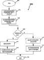
接下来参照图6,所示的是描绘可以结合参照图1-5讨论的实施例来实现的范例方法的流程图600。如所示,在框604,将已知信号(例如从信号生成器226提供的信号、系统100固有的信号、电源528提供的信号或其它可识别信号)与表示PV阵列102内的任何接地故障的信号一起引入至接地故障探测器和中断器的输入端(例如至电流变换器212、312、412、512)。接下来,在框606,在接地故障探测器和中断器的处理链(例如处理链212、214、216、218)的末端感测(例如通过控制器或数字信号处理器218)该已知信号。Referring next to FIG. 6 , shown is a
如所示,框608表示取决于是否探测到已知信号而影响方法的流动的条件分支。如果未探测到已知信号,则在框610,PV能量转换系统100关闭(例如通过响应于来自控制器或数字信号处理器218、318、418、518的信号将PV阵列102与系统100的其余部分去耦接),且在框612,发出(例如通过控制器或数字信号处理器218、318、418、518)表示接地故障探测器和中断器104、204、304、504运转不正常的通知。如果在框606识别到已知信号,则在框614,滤除已知信号(例如通过控制器或数字信号处理器218、318、418、518),且在框616,分析携带有表示PV阵列中的任何接地故障的信号的所滤波的信号,以确定是否存在接地故障状况。As shown, block 608 represents a conditional branch that affects the flow of the method depending on whether a known signal is detected. If no known signal is detected, then at
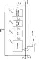
图7是包括双极光伏阵列702的光伏能量转换系统100的另一实施例的部分的示意图、以及一旦探测到需要中断系统的接地故障状况时,将双极光伏阵列702去耦接的新颖结构和方法。此类型的光伏阵列702通常称作双极连接阵列:具有诸如干线(rail)704和706的两条干线的光伏阵列,每条干线相对于地具有相反极性。此电路配置容许,使用光伏阵列的第一半710生成相对于地的正电压,使用光伏阵列的第二半712,生成相对于地的负电压。7 is a schematic diagram of a portion of another embodiment of a photovoltaic
如所示,主DC接触器714和716分别耦接于PV阵列702与干线704和706的输出端之间。主DC接触器714、716用于将PV阵列702耦接至光伏能量转换系统(例如系统100)的其余部分或用于将其与光伏能量转换系统当前其余部分去耦接,且输出端704、706典型地耦接至逆变器(例如逆变器106)。可以是结构与主DC接触器714和716类似的DC接触器的PV结(tie)718在围绕阵列的中线(neutral)708、709的点耦接至PV阵列702,如图7中所示例。辅助开关720和722也耦接至围绕阵列的中线708、709的点和地。保险丝724和726耦接至各辅助开关720和722。在一个实施例中,保险丝724和726定额为3安培,然而,本领域技术人员容易理解,基于特定实施和在系统的安装设定中施加于系统的代码和规则,该保险丝可以选择更宽广变化的值。在一个实施例中,控制器或数字信号处理器(例如218、318、418、518,图7中未示出)耦接至:主DC接触器714和716;PV结718;和辅助开关720、722,并且控制器或数字信号处理器(例如218、318、418、518,图7中未示出)用于设定这些部件的状态(断开或闭合)。As shown,
可以施加于光伏能量转换系统100的电代码(诸如National ElectricalCode-NEC)一些情况下要求光伏阵列的一侧接地(例如,见NEC Article690)。当例如与也要求中线点接地的120/240伏的AC公共事业输电线路(utility grid)相连接时,此要求可能存在问题。为了如代码所需地将阵列和公共事业输电线路均接地,光伏系统通常在逆变器106中采用隔离变压器(未示出),以容许阵列和输电线路均接地。Electrical codes that may be applied to the photovoltaic energy conversion system 100 (such as the National Electrical Code - NEC) in some cases require one side of the photovoltaic array to be grounded (eg, see NEC Article 690). This requirement can be problematic when, for example, connecting to a 120/240 volt AC utility grid which also requires a neutral point ground. To ground both the array and the utility power line as required by code, photovoltaic systems typically employ an isolation transformer (not shown) in the
当产生了需要中断的接地故障状况时,必需引起注意以确保光伏能量转换系统100安全关闭。当光伏阵列702的一半710和712之一内发生故障时,产生接地故障状况,并且接着可以进行用于将PV阵列702与系统去耦接的专门步骤。When a ground fault condition requiring interruption occurs, attention must be drawn to ensure that the photovoltaic
例如,可以首先断开DC接触器714和716,以通过逆变器的动作去除施加于阵列710和712上的虚接地。此配置称作“虚接地”。发明人向各测试代理演示了在于此描述的状况和配置时,此虚接地配置存在于地或地附近。一旦断开接触器714、716,则可以断开PV结接触器718以隔离正和负阵列710和712。最后,阵列710、712的中线708、709以开关720和722连接至地。如果仍存在地电流,则将断开适当的保险丝724或726,从而中断地电流并防止危险电流流动。For example,
下面参照图8,其示出了描绘可以结合参照图7讨论的实施例来实现的范例方法的流程图800。在框804,设定正常操作状况。在正常操作状况下(例如,在PV能量转换系统100已经安全启动时),闭合主DC接触器714和716以容许PV阵列702生成的电流流至逆变器(例如106),PV结718闭合,且辅助开关720和722断开。如框806反映的,接地故障探测器和中断器(例如104)连续操作以探测需要系统中断的接地故障状况,如框806中的“NO”分支所示例。如果探测到需要中断的接地故障状况,则方法行进至框808,在此,主DC接触器714和716断开,PV结接触器718断开,且辅助开关720和722闭合。Referring now to FIG. 8 , there is shown a
当探测到接地故障时,可以点亮逆变器的正面面板上的接地故障灯。如所描绘的,方法分支至框810,在此,采取动作以研究接地故障探测和中断警报的源。A ground fault light on the front panel of the inverter may be illuminated when a ground fault is detected. As depicted, the method branches to block 810 where action is taken to investigate the source of the ground fault detection and outage alarm.
分别在图7和8中公开的结构和方法的一个优点是它们减少了实施的成本。通过使用PV结718和辅助开关720和722来保持中线708和709为虚接地,避免了安装从PV阵列(典型地位于屋顶或其它遥远位置)至电服务面板的昂贵、笨重规格的中线的需求。在一个实施例中,用于接地故障探测器和中断器(例如104)的中断部分和保险丝部分的控制封装在安装于副底盘(sub-chassis)上的小框中。能够将副底盘容易地安装在屋顶或物理上设置PV阵列702的任何地方。虽然重型线(heavy duty wire)必需连接至副底盘,但是仅轻型线(light duty wire)需要延伸至逆变器。One advantage of the structures and methods disclosed in Figures 7 and 8, respectively, is that they reduce the cost of implementation. By using the
总之,除了其它,本发明还提供用于探测需要光伏能量转换系统的系统中断的接地故障状况的系统和方法。本领域技术人员容易认识到,可以在本发明中,在其使用和配置上进行许多变形和替代,以实现与于此描述的实施例所实现的基本相同的结果。因此,不是意在限制本发明于公开的范例形式。许多变形、更改和替代结构落入权利要求表述的公开的发明的范围和精神中。In summary, the present invention provides, among other things, systems and methods for detecting ground fault conditions requiring system interruption of photovoltaic energy conversion systems. Those skilled in the art will readily recognize that many variations and substitutions can be made in the present invention, in its use and arrangement, to achieve substantially the same results as achieved by the embodiments described herein. Therefore, there is no intention to limit the invention to the disclosed exemplary forms. Numerous variations, modifications, and alternative constructions fall within the scope and spirit of the disclosed invention as expressed in the claims.
Claims (16)
Translated fromChineseApplications Claiming Priority (3)
| Application Number | Priority Date | Filing Date | Title |
|---|---|---|---|
| US12/022,147US7768751B2 (en) | 2008-01-29 | 2008-01-29 | System and method for ground fault detection and interruption |
| US12/022,147 | 2008-01-29 | ||
| PCT/US2009/031549WO2009097207A2 (en) | 2008-01-29 | 2009-01-21 | System and method for ground fault detection and interruption |
Publications (2)
| Publication Number | Publication Date |
|---|---|
| CN101981776Atrue CN101981776A (en) | 2011-02-23 |
| CN101981776B CN101981776B (en) | 2013-10-30 |
Family
ID=40898978
Family Applications (1)
| Application Number | Title | Priority Date | Filing Date |
|---|---|---|---|
| CN2009801108006AActiveCN101981776B (en) | 2008-01-29 | 2009-01-21 | System and method for ground fault detection and interruption |
Country Status (6)
| Country | Link |
|---|---|
| US (2) | US7768751B2 (en) |
| EP (1) | EP2235806A4 (en) |
| KR (1) | KR20100103659A (en) |
| CN (1) | CN101981776B (en) |
| TW (1) | TW200933171A (en) |
| WO (1) | WO2009097207A2 (en) |
Cited By (3)
| Publication number | Priority date | Publication date | Assignee | Title |
|---|---|---|---|---|
| CN104704378A (en)* | 2012-08-03 | 2015-06-10 | 艾思玛太阳能技术股份公司 | Distributed detection of leakage current and fault current, and detection of string faults |
| CN110426601A (en)* | 2019-08-22 | 2019-11-08 | 金华电力设计院有限公司 | A kind of Fault Locating Method of earth-free photovoltaic system |
| CN114325233A (en)* | 2021-12-28 | 2022-04-12 | 国网江西省电力有限公司抚州供电分公司 | An Inverter-Based Sweep-Frequency Injection Signal Line Selection Method |
Families Citing this family (98)
| Publication number | Priority date | Publication date | Assignee | Title |
|---|---|---|---|---|
| US10693415B2 (en) | 2007-12-05 | 2020-06-23 | Solaredge Technologies Ltd. | Testing of a photovoltaic panel |
| US11881814B2 (en) | 2005-12-05 | 2024-01-23 | Solaredge Technologies Ltd. | Testing of a photovoltaic panel |
| US8384243B2 (en) | 2007-12-04 | 2013-02-26 | Solaredge Technologies Ltd. | Distributed power harvesting systems using DC power sources |
| US11296650B2 (en) | 2006-12-06 | 2022-04-05 | Solaredge Technologies Ltd. | System and method for protection during inverter shutdown in distributed power installations |
| US11309832B2 (en) | 2006-12-06 | 2022-04-19 | Solaredge Technologies Ltd. | Distributed power harvesting systems using DC power sources |
| US8013472B2 (en) | 2006-12-06 | 2011-09-06 | Solaredge, Ltd. | Method for distributed power harvesting using DC power sources |
| US8319471B2 (en) | 2006-12-06 | 2012-11-27 | Solaredge, Ltd. | Battery power delivery module |
| US11855231B2 (en) | 2006-12-06 | 2023-12-26 | Solaredge Technologies Ltd. | Distributed power harvesting systems using DC power sources |
| US12316274B2 (en) | 2006-12-06 | 2025-05-27 | Solaredge Technologies Ltd. | Pairing of components in a direct current distributed power generation system |
| US9130401B2 (en) | 2006-12-06 | 2015-09-08 | Solaredge Technologies Ltd. | Distributed power harvesting systems using DC power sources |
| US8963369B2 (en) | 2007-12-04 | 2015-02-24 | Solaredge Technologies Ltd. | Distributed power harvesting systems using DC power sources |
| US9112379B2 (en) | 2006-12-06 | 2015-08-18 | Solaredge Technologies Ltd. | Pairing of components in a direct current distributed power generation system |
| US11888387B2 (en) | 2006-12-06 | 2024-01-30 | Solaredge Technologies Ltd. | Safety mechanisms, wake up and shutdown methods in distributed power installations |
| US9088178B2 (en) | 2006-12-06 | 2015-07-21 | Solaredge Technologies Ltd | Distributed power harvesting systems using DC power sources |
| US11687112B2 (en) | 2006-12-06 | 2023-06-27 | Solaredge Technologies Ltd. | Distributed power harvesting systems using DC power sources |
| US8816535B2 (en) | 2007-10-10 | 2014-08-26 | Solaredge Technologies, Ltd. | System and method for protection during inverter shutdown in distributed power installations |
| US8319483B2 (en) | 2007-08-06 | 2012-11-27 | Solaredge Technologies Ltd. | Digital average input current control in power converter |
| US8473250B2 (en) | 2006-12-06 | 2013-06-25 | Solaredge, Ltd. | Monitoring of distributed power harvesting systems using DC power sources |
| US11735910B2 (en) | 2006-12-06 | 2023-08-22 | Solaredge Technologies Ltd. | Distributed power system using direct current power sources |
| US11569659B2 (en) | 2006-12-06 | 2023-01-31 | Solaredge Technologies Ltd. | Distributed power harvesting systems using DC power sources |
| US8618692B2 (en) | 2007-12-04 | 2013-12-31 | Solaredge Technologies Ltd. | Distributed power system using direct current power sources |
| US8947194B2 (en) | 2009-05-26 | 2015-02-03 | Solaredge Technologies Ltd. | Theft detection and prevention in a power generation system |
| US9172296B2 (en)* | 2007-05-23 | 2015-10-27 | Advanced Energy Industries, Inc. | Common mode filter system and method for a solar power inverter |
| US8203069B2 (en)* | 2007-08-03 | 2012-06-19 | Advanced Energy Industries, Inc | System, method, and apparatus for coupling photovoltaic arrays |
| US7768751B2 (en)* | 2008-01-29 | 2010-08-03 | Advanced Energy Industries, Inc. | System and method for ground fault detection and interruption |
| US8294296B2 (en)* | 2007-08-03 | 2012-10-23 | Advanced Energy Industries, Inc. | System, method, and apparatus for remotely coupling photovoltaic arrays |
| US20090078304A1 (en)* | 2007-09-26 | 2009-03-26 | Jack Arthur Gilmore | Photovoltaic charge abatement device, system, and method |
| US20090217964A1 (en)* | 2007-09-26 | 2009-09-03 | Advanced Energy Industries, Inc. | Device, system, and method for improving the efficiency of solar panels |
| US9291696B2 (en) | 2007-12-05 | 2016-03-22 | Solaredge Technologies Ltd. | Photovoltaic system power tracking method |
| WO2009072076A2 (en) | 2007-12-05 | 2009-06-11 | Solaredge Technologies Ltd. | Current sensing on a mosfet |
| WO2009073867A1 (en) | 2007-12-05 | 2009-06-11 | Solaredge, Ltd. | Parallel connected inverters |
| US11264947B2 (en) | 2007-12-05 | 2022-03-01 | Solaredge Technologies Ltd. | Testing of a photovoltaic panel |
| EP2225778B1 (en) | 2007-12-05 | 2019-06-26 | Solaredge Technologies Ltd. | Testing of a photovoltaic panel |
| CN105244905B (en) | 2007-12-05 | 2019-05-21 | 太阳能安吉有限公司 | Release mechanism in distributed power device is waken up and method for closing |
| US7964837B2 (en)* | 2007-12-31 | 2011-06-21 | Advanced Energy Industries, Inc. | Photovoltaic inverter interface device, system, and method |
| US8111052B2 (en) | 2008-03-24 | 2012-02-07 | Solaredge Technologies Ltd. | Zero voltage switching |
| EP2407996B1 (en)* | 2008-03-31 | 2013-09-18 | SMA Solar Technology AG | Current sensing arrangement in an inverter |
| EP2294669B8 (en) | 2008-05-05 | 2016-12-07 | Solaredge Technologies Ltd. | Direct current power combiner |
| US8461508B2 (en) | 2008-08-10 | 2013-06-11 | Advanced Energy Industries, Inc. | Device, system, and method for sectioning and coupling multiple photovoltaic strings |
| US7619200B1 (en)* | 2008-08-10 | 2009-11-17 | Advanced Energy Industries, Inc. | Device system and method for coupling multiple photovoltaic arrays |
| US20100085670A1 (en)* | 2008-10-07 | 2010-04-08 | Krishnan Palaniswami | Photovoltaic module monitoring system |
| US8362644B2 (en)* | 2008-12-02 | 2013-01-29 | Advanced Energy Industries, Inc. | Device, system, and method for managing an application of power from photovoltaic arrays |
| EP2602831B1 (en) | 2009-05-22 | 2014-07-16 | Solaredge Technologies Ltd. | Electrically isolated heat dissipating junction box |
| EP2296244B1 (en)* | 2009-08-06 | 2015-02-18 | SMA Solar Technology AG | Method and device for connecting at least one string of a photovoltaic assembly with an inverter |
| US10424935B2 (en) | 2009-09-15 | 2019-09-24 | Rajiv Kumar Varma | Multivariable modulator controller for power generation facility |
| US8390297B2 (en)* | 2009-10-02 | 2013-03-05 | Semiconductor Components Industries, Llc | Ground fault circuit interrupter and method |
| US12418177B2 (en) | 2009-10-24 | 2025-09-16 | Solaredge Technologies Ltd. | Distributed power system using direct current power sources |
| US8710699B2 (en) | 2009-12-01 | 2014-04-29 | Solaredge Technologies Ltd. | Dual use photovoltaic system |
| TWI383162B (en)* | 2009-12-22 | 2013-01-21 | Univ Nat Taipei Technology | Fault location method |
| US8766696B2 (en) | 2010-01-27 | 2014-07-01 | Solaredge Technologies Ltd. | Fast voltage level shifter circuit |
| US8564916B2 (en)* | 2010-02-16 | 2013-10-22 | Western Gas And Electric Company | Photovoltaic array ground fault detection method for utility-scale grounded solar electric power generating systems |
| US8618456B2 (en)* | 2010-02-16 | 2013-12-31 | Western Gas And Electric Company | Inverter for a three-phase AC photovoltaic system |
| CN102207528A (en)* | 2010-03-31 | 2011-10-05 | 鸿富锦精密工业(深圳)有限公司 | Leakage early-warning device and socket |
| DE102010017747A1 (en)* | 2010-05-03 | 2011-11-03 | Sma Solar Technology Ag | Method for limiting the generator voltage of a photovoltaic system in case of danger and photovoltaic system |
| US8643985B2 (en)* | 2010-07-23 | 2014-02-04 | Schneider Electric Solar Inverters Usa, Inc. | Photovoltaic bipolar to monopolar source circuit converter with frequency selective grounding |
| US20120049855A1 (en)* | 2010-08-24 | 2012-03-01 | Crites David E | Dark IV monitoring system for photovoltaic installations |
| US10615743B2 (en)* | 2010-08-24 | 2020-04-07 | David Crites | Active and passive monitoring system for installed photovoltaic strings, substrings, and modules |
| US20120049627A1 (en)* | 2010-08-24 | 2012-03-01 | Sanyo Electric Co., Ltd. | Current collecting box for photovoltaic power generation |
| US10673222B2 (en) | 2010-11-09 | 2020-06-02 | Solaredge Technologies Ltd. | Arc detection and prevention in a power generation system |
| GB2485527B (en) | 2010-11-09 | 2012-12-19 | Solaredge Technologies Ltd | Arc detection and prevention in a power generation system |
| US10673229B2 (en) | 2010-11-09 | 2020-06-02 | Solaredge Technologies Ltd. | Arc detection and prevention in a power generation system |
| US10230310B2 (en) | 2016-04-05 | 2019-03-12 | Solaredge Technologies Ltd | Safety switch for photovoltaic systems |
| GB2486408A (en) | 2010-12-09 | 2012-06-20 | Solaredge Technologies Ltd | Disconnection of a string carrying direct current |
| DE102010055550A1 (en) | 2010-12-22 | 2012-06-28 | Sma Solar Technology Ag | Inverter, power plant and method of operating a power plant |
| GB2483317B (en) | 2011-01-12 | 2012-08-22 | Solaredge Technologies Ltd | Serially connected inverters |
| US8760170B2 (en)* | 2011-01-28 | 2014-06-24 | Schneider Electric Solar Inverters Usa, Inc. | Fuse continuity detection |
| TW201237431A (en)* | 2011-03-04 | 2012-09-16 | Wistron Corp | A detecting apparatus and a detecting method for detecting a ground wire |
| US20120256490A1 (en)* | 2011-04-07 | 2012-10-11 | Yongchun Zheng | Integrated Expandable Grid-Ready Solar Electrical Generator |
| US20130015875A1 (en)* | 2011-07-13 | 2013-01-17 | United Solar Ovonic Llc | Failure detection system for photovoltaic array |
| US8570005B2 (en) | 2011-09-12 | 2013-10-29 | Solaredge Technologies Ltd. | Direct current link circuit |
| GB2498365A (en) | 2012-01-11 | 2013-07-17 | Solaredge Technologies Ltd | Photovoltaic module |
| US9853565B2 (en) | 2012-01-30 | 2017-12-26 | Solaredge Technologies Ltd. | Maximized power in a photovoltaic distributed power system |
| GB2498791A (en) | 2012-01-30 | 2013-07-31 | Solaredge Technologies Ltd | Photovoltaic panel circuitry |
| GB2498790A (en) | 2012-01-30 | 2013-07-31 | Solaredge Technologies Ltd | Maximising power in a photovoltaic distributed power system |
| GB2499991A (en) | 2012-03-05 | 2013-09-11 | Solaredge Technologies Ltd | DC link circuit for photovoltaic array |
| WO2013141495A1 (en)* | 2012-03-23 | 2013-09-26 | (주)케이디파워 | Multi-inverter photovoltaic power generation system |
| EP3499695B1 (en) | 2012-05-25 | 2024-09-18 | Solaredge Technologies Ltd. | Circuit for interconnected direct current power sources |
| US10115841B2 (en) | 2012-06-04 | 2018-10-30 | Solaredge Technologies Ltd. | Integrated photovoltaic panel circuitry |
| CN102842881A (en)* | 2012-07-20 | 2012-12-26 | 江苏兆伏新能源有限公司 | Grounding protection device and thin film battery generating device based on grounding protection device |
| US9287802B2 (en)* | 2012-11-19 | 2016-03-15 | Advanced Energy Industries, Inc. | Passive unipolar referencing for non-isolated inverters |
| TWI466403B (en)* | 2013-01-30 | 2014-12-21 | Chicony Power Tech Co Ltd | Solar energy conversion apparatus |
| US9548619B2 (en) | 2013-03-14 | 2017-01-17 | Solaredge Technologies Ltd. | Method and apparatus for storing and depleting energy |
| US9941813B2 (en) | 2013-03-14 | 2018-04-10 | Solaredge Technologies Ltd. | High frequency multi-level inverter |
| EP3506370B1 (en) | 2013-03-15 | 2023-12-20 | Solaredge Technologies Ltd. | Bypass mechanism |
| US9318974B2 (en) | 2014-03-26 | 2016-04-19 | Solaredge Technologies Ltd. | Multi-level inverter with flying capacitor topology |
| US10992255B2 (en) | 2014-10-28 | 2021-04-27 | Sunpower Corporation | Photovoltaic module or array shutdown |
| AU2015364718B2 (en) | 2014-12-16 | 2019-11-28 | Marici Holdings The Netherlands B.V. | Energy panel arrangement power dissipation |
| WO2016123305A1 (en) | 2015-01-28 | 2016-08-04 | Abb Technology Ag | Energy panel arrangement shutdown |
| WO2016134356A1 (en) | 2015-02-22 | 2016-08-25 | Abb Technology Ag | Photovoltaic string reverse polarity detection |
| US10103537B2 (en) | 2015-12-16 | 2018-10-16 | Ge Energy Power Conversion Technology Ltd | Ground fault detection and interrupt system |
| US10599113B2 (en) | 2016-03-03 | 2020-03-24 | Solaredge Technologies Ltd. | Apparatus and method for determining an order of power devices in power generation systems |
| CN107153212B (en) | 2016-03-03 | 2023-07-28 | 太阳能安吉科技有限公司 | Method for mapping a power generation facility |
| US11081608B2 (en) | 2016-03-03 | 2021-08-03 | Solaredge Technologies Ltd. | Apparatus and method for determining an order of power devices in power generation systems |
| US11177663B2 (en) | 2016-04-05 | 2021-11-16 | Solaredge Technologies Ltd. | Chain of power devices |
| US11018623B2 (en) | 2016-04-05 | 2021-05-25 | Solaredge Technologies Ltd. | Safety switch for photovoltaic systems |
| US12057807B2 (en) | 2016-04-05 | 2024-08-06 | Solaredge Technologies Ltd. | Chain of power devices |
| JP7156554B2 (en)* | 2020-04-27 | 2022-10-19 | 東芝三菱電機産業システム株式会社 | Power converter and power conversion system |
| IT202300003573A1 (en) | 2023-02-28 | 2024-08-28 | Lauria Massimo Alfredo | MONITORING AND SECTIONING DEVICE FOR PHOTOVOLTAIC PANEL STRINGS |
Citations (3)
| Publication number | Priority date | Publication date | Assignee | Title |
|---|---|---|---|---|
| CN1201157C (en)* | 2001-02-02 | 2005-05-11 | 佳能株式会社 | Device and method for detecting earthing failure in solar generating system |
| JP2006187150A (en)* | 2004-12-28 | 2006-07-13 | Omron Corp | Power conditioner and its self-diagnosis method |
| US7292419B1 (en)* | 2001-09-09 | 2007-11-06 | Nemir David C | Fault interrupter with interchangeable line load connections |
Family Cites Families (56)
| Publication number | Priority date | Publication date | Assignee | Title |
|---|---|---|---|---|
| DE2513471A1 (en)* | 1975-03-26 | 1976-04-22 | Braun Ag | CIRCUIT ARRANGEMENT FOR SWITCHING OFF A CHOPPER |
| US3986097A (en)* | 1975-06-30 | 1976-10-12 | Bell Telephone Laboratories, Incorporated | Bilateral direct current converters |
| US4025862A (en)* | 1975-12-04 | 1977-05-24 | La Telemecanique Electrique | Power supply with chopping circuit |
| US4054827A (en)* | 1976-04-12 | 1977-10-18 | The United States Of America As Represented By The Secretary Of The Army | Voltage boost circuit for DC power supply |
| US4128793A (en)* | 1977-07-25 | 1978-12-05 | Allis-Chalmers Corporation | Power circuit for variable frequency, variable magnitude power conditioning system |
| US4161023A (en)* | 1977-09-07 | 1979-07-10 | The United States Of America As Represented By The United States Department Of Energy | Up-and-down chopper circuit |
| FR2576722B1 (en)* | 1985-01-25 | 1987-04-30 | Centre Nat Etd Spatiales | DIRECT CURRENT SUPPLY WITH ADJUSTABLE OPERATING POINT |
| DE3606462A1 (en)* | 1986-02-28 | 1987-09-03 | Leybold Heraeus Gmbh & Co Kg | INVERTER WITH A DC VOLTAGE PART AND A CHOPPER PART |
| US5270636A (en)* | 1992-02-18 | 1993-12-14 | Lafferty Donald L | Regulating control circuit for photovoltaic source employing switches, energy storage, and pulse width modulation controller |
| JPH0749721A (en) | 1993-08-09 | 1995-02-21 | Sanyo Electric Co Ltd | Protection device for electric apparatus using solar battery as power supply |
| US5451962A (en)* | 1994-08-26 | 1995-09-19 | Martin Marietta Corporation | Boost regulated capacitor multiplier for pulse load |
| US5781419A (en)* | 1996-04-12 | 1998-07-14 | Soft Switching Technologies, Inc. | Soft switching DC-to-DC converter with coupled inductors |
| KR100205229B1 (en)* | 1996-05-15 | 1999-07-01 | 윤종용 | Solar cell power supply |
| JP3630854B2 (en) | 1996-06-24 | 2005-03-23 | 三洋電機株式会社 | Grid-connected power supply system |
| JPH10229679A (en) | 1997-02-18 | 1998-08-25 | Mitsubishi Electric Corp | Grid-connected inverter device |
| US5923100A (en)* | 1997-03-31 | 1999-07-13 | Lockheed Martin Corporation | Apparatus for controlling a solar array power system |
| JP3406512B2 (en) | 1998-03-27 | 2003-05-12 | 株式会社荏原電産 | Control method and control device for inverter device |
| US6115273A (en)* | 1998-07-09 | 2000-09-05 | Illinois Tool Works Inc. | Power converter with low loss switching |
| JP2000295786A (en) | 1999-04-02 | 2000-10-20 | Toshiba Fa Syst Eng Corp | How to connect a solar cell inverter unit |
| JP2000358370A (en) | 1999-06-14 | 2000-12-26 | Densei Lambda Kk | Multi-output stabilized dc power supply |
| US6266260B1 (en)* | 1999-09-03 | 2001-07-24 | Powerware Corporation | Inverter having center switch and uninterruptible power supply implementing same |
| JP2001161032A (en)* | 1999-12-01 | 2001-06-12 | Canon Inc | Grid-connected power conditioner and power generation system using the same |
| US6404655B1 (en)* | 1999-12-07 | 2002-06-11 | Semikron, Inc. | Transformerless 3 phase power inverter |
| US6593520B2 (en)* | 2000-02-29 | 2003-07-15 | Canon Kabushiki Kaisha | Solar power generation apparatus and control method therefor |
| JP2001275259A (en)* | 2000-03-29 | 2001-10-05 | Canon Inc | Grid-connected inverter and distributed generation system |
| FR2819653B1 (en)* | 2001-01-16 | 2003-04-11 | Centre Nat Rech Scient | CONTROL OF A POWER CONVERTER FOR AN AUTOMATIC SEARCH FOR THE MAXIMUM POINT OF POWER |
| JP3394996B2 (en)* | 2001-03-09 | 2003-04-07 | 独立行政法人産業技術総合研究所 | Maximum power operating point tracking method and device |
| JP2002319687A (en) | 2001-04-20 | 2002-10-31 | Furukawa Electric Co Ltd:The | Solar power generation system with snow melting function |
| US20020170591A1 (en)* | 2001-05-15 | 2002-11-21 | Pharmaseq, Inc. | Method and apparatus for powering circuitry with on-chip solar cells within a common substrate |
| JP2003158282A (en)* | 2001-08-30 | 2003-05-30 | Canon Inc | Solar power system |
| JP2003098215A (en)* | 2001-09-26 | 2003-04-03 | Canon Inc | Apparatus and method for ground fault detection in a power conversion system |
| JP2003124492A (en) | 2001-10-18 | 2003-04-25 | Tdk Corp | Solar cell module |
| US7038333B2 (en)* | 2002-02-15 | 2006-05-02 | The Gillette Company | Hybrid power supply |
| JP2004015941A (en) | 2002-06-10 | 2004-01-15 | Advantest Corp | Positive/negative dc power supply unit and semiconductor testing device using the same |
| US7371963B2 (en)* | 2002-07-31 | 2008-05-13 | Kyocera Corporation | Photovoltaic power generation system |
| US6914418B2 (en)* | 2003-04-21 | 2005-07-05 | Phoenixtec Power Co., Ltd. | Multi-mode renewable power converter system |
| JP2004343909A (en) | 2003-05-16 | 2004-12-02 | Fuji Photo Film Co Ltd | Power supply circuit and electronic equipment |
| US7050311B2 (en)* | 2003-11-25 | 2006-05-23 | Electric Power Research Institute, Inc. | Multilevel converter based intelligent universal transformer |
| US20050139259A1 (en)* | 2003-12-30 | 2005-06-30 | Robert Steigerwald | Transformerless power conversion in an inverter for a photovoltaic system |
| JP4225923B2 (en) | 2004-01-19 | 2009-02-18 | 三洋電機株式会社 | Inverter for grid connection |
| US7498693B2 (en)* | 2004-02-18 | 2009-03-03 | Diversified Technologies, Inc. | More compact and higher reliability power source system |
| KR100671788B1 (en) | 2005-03-18 | 2007-01-22 | 주식회사 다윈전자 | Power module circuit |
| US20060227472A1 (en)* | 2005-04-07 | 2006-10-12 | William Taylor | Inverter ground fault circuit |
| GB0509045D0 (en)* | 2005-05-04 | 2005-06-08 | Deepstream Technologies Ltd | Circuit protection device and test facility to simulate a fault condition |
| WO2007022955A1 (en) | 2005-08-22 | 2007-03-01 | Conergy Ag | Solar cell |
| JP5401003B2 (en) | 2006-01-27 | 2014-01-29 | シャープ株式会社 | Solar power system |
| US9172296B2 (en)* | 2007-05-23 | 2015-10-27 | Advanced Energy Industries, Inc. | Common mode filter system and method for a solar power inverter |
| US8203069B2 (en)* | 2007-08-03 | 2012-06-19 | Advanced Energy Industries, Inc | System, method, and apparatus for coupling photovoltaic arrays |
| US7768751B2 (en)* | 2008-01-29 | 2010-08-03 | Advanced Energy Industries, Inc. | System and method for ground fault detection and interruption |
| US8294296B2 (en)* | 2007-08-03 | 2012-10-23 | Advanced Energy Industries, Inc. | System, method, and apparatus for remotely coupling photovoltaic arrays |
| US20090078304A1 (en)* | 2007-09-26 | 2009-03-26 | Jack Arthur Gilmore | Photovoltaic charge abatement device, system, and method |
| US20090217964A1 (en)* | 2007-09-26 | 2009-09-03 | Advanced Energy Industries, Inc. | Device, system, and method for improving the efficiency of solar panels |
| US7701081B2 (en)* | 2007-12-31 | 2010-04-20 | Advanced Energy Industries, Inc. | System, method and apparatus for providing direct current |
| US7964837B2 (en)* | 2007-12-31 | 2011-06-21 | Advanced Energy Industries, Inc. | Photovoltaic inverter interface device, system, and method |
| US7619200B1 (en)* | 2008-08-10 | 2009-11-17 | Advanced Energy Industries, Inc. | Device system and method for coupling multiple photovoltaic arrays |
| US8362644B2 (en)* | 2008-12-02 | 2013-01-29 | Advanced Energy Industries, Inc. | Device, system, and method for managing an application of power from photovoltaic arrays |
- 2008
- 2008-01-29USUS12/022,147patent/US7768751B2/ennot_activeExpired - Fee Related
- 2009
- 2009-01-21WOPCT/US2009/031549patent/WO2009097207A2/enactiveApplication Filing
- 2009-01-21EPEP09705701.2Apatent/EP2235806A4/ennot_activeWithdrawn
- 2009-01-21KRKR1020107017112Apatent/KR20100103659A/ennot_activeCeased
- 2009-01-21CNCN2009801108006Apatent/CN101981776B/enactiveActive
- 2009-01-22TWTW98102464Apatent/TW200933171A/enunknown
- 2010
- 2010-07-05USUS12/830,380patent/US8134812B2/enactiveActive
Patent Citations (3)
| Publication number | Priority date | Publication date | Assignee | Title |
|---|---|---|---|---|
| CN1201157C (en)* | 2001-02-02 | 2005-05-11 | 佳能株式会社 | Device and method for detecting earthing failure in solar generating system |
| US7292419B1 (en)* | 2001-09-09 | 2007-11-06 | Nemir David C | Fault interrupter with interchangeable line load connections |
| JP2006187150A (en)* | 2004-12-28 | 2006-07-13 | Omron Corp | Power conditioner and its self-diagnosis method |
Cited By (3)
| Publication number | Priority date | Publication date | Assignee | Title |
|---|---|---|---|---|
| CN104704378A (en)* | 2012-08-03 | 2015-06-10 | 艾思玛太阳能技术股份公司 | Distributed detection of leakage current and fault current, and detection of string faults |
| CN110426601A (en)* | 2019-08-22 | 2019-11-08 | 金华电力设计院有限公司 | A kind of Fault Locating Method of earth-free photovoltaic system |
| CN114325233A (en)* | 2021-12-28 | 2022-04-12 | 国网江西省电力有限公司抚州供电分公司 | An Inverter-Based Sweep-Frequency Injection Signal Line Selection Method |
Also Published As
| Publication number | Publication date |
|---|---|
| WO2009097207A3 (en) | 2009-10-15 |
| US20090190275A1 (en) | 2009-07-30 |
| KR20100103659A (en) | 2010-09-27 |
| CN101981776B (en) | 2013-10-30 |
| TW200933171A (en) | 2009-08-01 |
| US8134812B2 (en) | 2012-03-13 |
| EP2235806A4 (en) | 2014-07-30 |
| US20110157753A1 (en) | 2011-06-30 |
| WO2009097207A2 (en) | 2009-08-06 |
| US7768751B2 (en) | 2010-08-03 |
| EP2235806A2 (en) | 2010-10-06 |
Similar Documents
| Publication | Publication Date | Title |
|---|---|---|
| CN101981776A (en) | Systems and methods for ground fault detection and interruption | |
| US7576449B2 (en) | Method for converting direct voltage into three-phase alternating voltage | |
| US8203069B2 (en) | System, method, and apparatus for coupling photovoltaic arrays | |
| US9865411B2 (en) | Safety device for a photovoltaic system | |
| US8837097B2 (en) | Protection, monitoring or indication apparatus for a direct current electrical generating apparatus or a plurality of strings | |
| US8717720B2 (en) | Systems and methods for providing arc fault and/or ground fault protection for distributed generation sources | |
| JP5542942B2 (en) | Grounding device | |
| CN102906847B (en) | Leakage detection device with unexpected action prevention function | |
| US20150309104A1 (en) | Differential current monitoring device with arc detection | |
| CN105846758A (en) | Photovoltaic power generation system and turn-off device | |
| US9716407B2 (en) | Standby power supply system and methods for isolating a local power distribution network from a superordinate power supply network | |
| JP2003087978A (en) | Power generator, distribution board, and power supply system using them | |
| JP2015532581A (en) | System for protecting multiple DC voltage sources | |
| JP2018182970A (en) | Power converter and distributed power supply system | |
| JP2012075250A (en) | Insulation ground fault monitoring device with adoption lock | |
| KR100437446B1 (en) | Sub-system connecting device in power supply system | |
| JPH06343231A (en) | System-interconnection protecting apparatus | |
| JP2025030940A (en) | Power conversion device and power conditioner | |
| JP2005094897A (en) | Isolated operation prevention device | |
| WO2024024214A1 (en) | Distributed electric power source electric power distribution system and method for controlling distributed electric power source electric power distribution system | |
| KR200264800Y1 (en) | Sub-system connecting device in power supply system | |
| JP2025141014A (en) | Power conversion devices and power conditioners | |
| CN116316397A (en) | Electrical protection system and method with improved selectivity | |
| JPH06343230A (en) | System-interconnection protecting apparatus | |
| JPH0898410A (en) | Grid interconnection protection device |
Legal Events
| Date | Code | Title | Description |
|---|---|---|---|
| C06 | Publication | ||
| PB01 | Publication | ||
| C10 | Entry into substantive examination | ||
| SE01 | Entry into force of request for substantive examination | ||
| C14 | Grant of patent or utility model | ||
| GR01 | Patent grant | ||
| CI01 | Publication of corrected invention patent application | Correction item:First inventor Correct:Gilmore Jack A. False:Gilmore Jack A. Number:44 Volume:29 | |
| CI03 | Correction of invention patent | Correction item:First inventor Correct:Gilmore Jack A. False:Gilmore Jack A. Number:44 Page:The title page Volume:29 | |
| ERR | Gazette correction | Free format text:CORRECT: THE FIRST INVENTOR; FROM: GILMORE JACK A.. TO: GILMORE JACK A. | |
| RECT | Rectification | ||
| TR01 | Transfer of patent right | Effective date of registration:20190412 Address after:Singapore Singapore Patentee after:Advanced Engineering Solutions Global Holdings Private Ltd. Address before:American Colorado Patentee before:Advanced Energy Industries, Inc. | |
| TR01 | Transfer of patent right |