CN101977656A - Method and device for improving the efficiency of non-invasive ventilation - Google Patents
Method and device for improving the efficiency of non-invasive ventilationDownload PDFInfo
- Publication number
- CN101977656A CN101977656ACN2009801095400ACN200980109540ACN101977656ACN 101977656 ACN101977656 ACN 101977656ACN 2009801095400 ACN2009801095400 ACN 2009801095400ACN 200980109540 ACN200980109540 ACN 200980109540ACN 101977656 ACN101977656 ACN 101977656A
- Authority
- CN
- China
- Prior art keywords
- manifold
- house steward
- nose
- assembly
- interface assembly
- Prior art date
- Legal status (The legal status is an assumption and is not a legal conclusion. Google has not performed a legal analysis and makes no representation as to the accuracy of the status listed.)
- Pending
Links
Images


Classifications
- A—HUMAN NECESSITIES
- A61—MEDICAL OR VETERINARY SCIENCE; HYGIENE
- A61M—DEVICES FOR INTRODUCING MEDIA INTO, OR ONTO, THE BODY; DEVICES FOR TRANSDUCING BODY MEDIA OR FOR TAKING MEDIA FROM THE BODY; DEVICES FOR PRODUCING OR ENDING SLEEP OR STUPOR
- A61M16/00—Devices for influencing the respiratory system of patients by gas treatment, e.g. ventilators; Tracheal tubes
- A61M16/06—Respiratory or anaesthetic masks
- A61M16/0605—Means for improving the adaptation of the mask to the patient
- A61M16/0616—Means for improving the adaptation of the mask to the patient with face sealing means comprising a flap or membrane projecting inwards, such that sealing increases with increasing inhalation gas pressure
- A61M16/0622—Means for improving the adaptation of the mask to the patient with face sealing means comprising a flap or membrane projecting inwards, such that sealing increases with increasing inhalation gas pressure having an underlying cushion
- A—HUMAN NECESSITIES
- A61—MEDICAL OR VETERINARY SCIENCE; HYGIENE
- A61M—DEVICES FOR INTRODUCING MEDIA INTO, OR ONTO, THE BODY; DEVICES FOR TRANSDUCING BODY MEDIA OR FOR TAKING MEDIA FROM THE BODY; DEVICES FOR PRODUCING OR ENDING SLEEP OR STUPOR
- A61M16/00—Devices for influencing the respiratory system of patients by gas treatment, e.g. ventilators; Tracheal tubes
- A61M16/06—Respiratory or anaesthetic masks
- A61M16/0666—Nasal cannulas or tubing
- A—HUMAN NECESSITIES
- A61—MEDICAL OR VETERINARY SCIENCE; HYGIENE
- A61M—DEVICES FOR INTRODUCING MEDIA INTO, OR ONTO, THE BODY; DEVICES FOR TRANSDUCING BODY MEDIA OR FOR TAKING MEDIA FROM THE BODY; DEVICES FOR PRODUCING OR ENDING SLEEP OR STUPOR
- A61M16/00—Devices for influencing the respiratory system of patients by gas treatment, e.g. ventilators; Tracheal tubes
- A61M16/08—Bellows; Connecting tubes ; Water traps; Patient circuits
- A61M16/0816—Joints or connectors
- A61M16/0825—Joints or connectors with ball-sockets
- A—HUMAN NECESSITIES
- A61—MEDICAL OR VETERINARY SCIENCE; HYGIENE
- A61M—DEVICES FOR INTRODUCING MEDIA INTO, OR ONTO, THE BODY; DEVICES FOR TRANSDUCING BODY MEDIA OR FOR TAKING MEDIA FROM THE BODY; DEVICES FOR PRODUCING OR ENDING SLEEP OR STUPOR
- A61M16/00—Devices for influencing the respiratory system of patients by gas treatment, e.g. ventilators; Tracheal tubes
- A61M16/08—Bellows; Connecting tubes ; Water traps; Patient circuits
- A61M16/0875—Connecting tubes
- A—HUMAN NECESSITIES
- A61—MEDICAL OR VETERINARY SCIENCE; HYGIENE
- A61M—DEVICES FOR INTRODUCING MEDIA INTO, OR ONTO, THE BODY; DEVICES FOR TRANSDUCING BODY MEDIA OR FOR TAKING MEDIA FROM THE BODY; DEVICES FOR PRODUCING OR ENDING SLEEP OR STUPOR
- A61M16/00—Devices for influencing the respiratory system of patients by gas treatment, e.g. ventilators; Tracheal tubes
- A61M16/06—Respiratory or anaesthetic masks
- A61M16/0683—Holding devices therefor
- A—HUMAN NECESSITIES
- A61—MEDICAL OR VETERINARY SCIENCE; HYGIENE
- A61M—DEVICES FOR INTRODUCING MEDIA INTO, OR ONTO, THE BODY; DEVICES FOR TRANSDUCING BODY MEDIA OR FOR TAKING MEDIA FROM THE BODY; DEVICES FOR PRODUCING OR ENDING SLEEP OR STUPOR
- A61M2210/00—Anatomical parts of the body
- A61M2210/06—Head
- A61M2210/0618—Nose
Landscapes
- Health & Medical Sciences (AREA)
- Pulmonology (AREA)
- Life Sciences & Earth Sciences (AREA)
- Animal Behavior & Ethology (AREA)
- Anesthesiology (AREA)
- Biomedical Technology (AREA)
- Heart & Thoracic Surgery (AREA)
- Hematology (AREA)
- Emergency Medicine (AREA)
- Engineering & Computer Science (AREA)
- General Health & Medical Sciences (AREA)
- Public Health (AREA)
- Veterinary Medicine (AREA)
- Otolaryngology (AREA)
- Orthopedics, Nursing, And Contraception (AREA)
- Respiratory Apparatuses And Protective Means (AREA)
Abstract
Description
Translated fromChinese相关申请的交叉引用Cross References to Related Applications
本申请要求享有2008年1月18日提交的美国临时专利申请No.61/006,548和2008年10月17日提交的美国临时专利申请No.61/106,414的优先权,这两份申请都通过整体引用被结合于此。本申请还通过整体引用结合了以下文献:2008年3月13日提交的美国专利申请No.12/076,062;2008年8月5日授权的美国专利No.7,406,966;2003年8月18日提交的美国临时专利申请No.60/495,812;和2003年10月14日提交的美国临时专利申请No.60/511,820。This application claims the benefit of priority to U.S. Provisional Patent Application No. 61/006,548, filed January 18, 2008, and U.S. Provisional Patent Application No. 61/106,414, filed October 17, 2008, both of which have been adopted as a whole References are hereby incorporated. This application also incorporates by reference the following documents in their entireties: U.S. Patent Application No. 12/076,062, filed March 13, 2008; U.S. Patent No. 7,406,966, issued August 5, 2008; U.S. Provisional Patent Application No. 60/495,812; and U.S. Provisional Patent Application No. 60/511,820, filed October 14, 2003.
技术领域technical field
本发明涉及无创通气(NIV)病人界面装置,它提供了供空气进入病人气道和肺内的路径。更特别地,本发明可以应用于阻塞性睡眠呼吸暂停(OSA)——一种上气道阻塞的情形;然而,这里的教导也适合于其他呼吸情形。The present invention relates to a non-invasive ventilation (NIV) patient interface device that provides a pathway for supply air into a patient's airways and lungs. More particularly, the invention may be applied to obstructive sleep apnea (OSA), a condition of upper airway obstruction; however, the teachings herein are applicable to other breathing conditions as well.
背景技术Background technique
无创通气病人界面装置被紧固在病人鼻子和/或嘴的外面,并且不深入气道。这些装置用于各种医学程序,例如紧急通风、麻醉供给和恢复、雾化药物输送、增进自然呼吸、补充氧气供给、机械通风、戒绝机械通风和用于治疗阻塞性睡眠呼吸暂停。就阻塞性睡眠呼吸暂停而言,在病人的睡眠过程中连续气道正压力(CPAP)或者大小连续变化的气道正压力(VPAP)通过该界面装置被输送到病人的气道,以防止气道阻塞。对于所有的气道正压力应用来说,阻塞性睡眠呼吸暂停是独特的,因为这种治疗优选最低限度地介入,以便不干扰病人的睡眠,而在其他气道正压力应用中,较少关心对睡眠的干扰。有三种不同形式的无创通气界面装置:鼻子界面、口腔界面和口腔-鼻子混合界面。有两种类型的鼻子界面形式:位于鼻子上方的鼻罩和紧密接触鼻孔的鼻管或鼻枕。Non-invasive ventilation patient interface devices are secured outside the patient's nose and/or mouth and do not penetrate deep into the airway. These devices are used in a variety of medical procedures such as emergency ventilation, anesthesia delivery and recovery, aerosolized drug delivery, enhancement of natural respiration, supplemental oxygen delivery, mechanical ventilation, weaning from mechanical ventilation and for the treatment of obstructive sleep apnea. In the case of obstructive sleep apnea, continuous positive airway pressure (CPAP) or continuously variable positive airway pressure (VPAP) is delivered to the patient's airway through the interface device during the patient's sleep to prevent respiratory distress. Road blocked. Obstructive sleep apnea is unique to all positive airway pressure applications in that this treatment is preferably minimally invasive so as not to disturb the patient's sleep, whereas in other positive airway pressure applications, less concern Interference with sleep. There are three different forms of noninvasive ventilation interface devices: nasal interfaces, oral interfaces, and hybrid oral-nasal interfaces. There are two types of nasal interface forms: nasal masks that sit over the nose and nasal tubes or pillows that closely contact the nostrils.
发明内容Contents of the invention
本发明提供一种气道正压力鼻枕通气界面装置,优选包括或者提供下列特征中的至少一个:具有在解剖学上优选符合用户面部的弓形曲线的总管;在任何时候仅安装在总管一侧并且在任何时候仅延伸到面部一侧的供气管道组件;低流阻设计;舒服且有效但又不深入鼻孔的鼻孔密封;舒服且对于整个面部不突出的设计;便于安装和和拆卸的装置;以及允许用户侧躺并且没有不适或者装置故障的装置。总管和气源优选可以设计有曲线,以配合用户的解剖学结构并将该装置定位在面部的最舒服的部分上。在特别优选的实施例中,低轮廓设计、气源的单侧连接、旋转连接、以及总管的曲线和形状,这些特征的组合优选允许根据本发明的某些实施例的通气界面装置对用户来说硌得最轻,并且舒服。另外,总管和气源优选可以通过病人使用介于头部带和总管之间的接头佩戴,该接头优选包括至少两个不同的调节,这样优选便于适应各人的头部形状和尺寸以及最大舒适度。The present invention provides a positive airway pressure nasal pillow ventilation interface device, preferably including or providing at least one of the following features: a manifold that preferably conforms to the arcuate curve of the user's face anatomically; installed on only one side of the manifold at any time Air supply tube assembly that extends only to one side of the face at any time; low flow resistance design; comfortable and effective nostril seal that does not penetrate into the nostril; comfortable and unobtrusive design for the entire face; easy to install and remove the device ; and a device that allows a user to lie on their side without discomfort or device failure. The manifold and air source can preferably be designed with curves to fit the user's anatomy and position the device on the most comfortable part of the face. In particularly preferred embodiments, the combination of low profile design, single-sided connection of the air source, swivel connection, and the curve and shape of the manifold preferably allows ventilation interface devices according to certain embodiments of the present invention to be more comfortable for the user. It is lightest to say and is comfortable. In addition, the manifold and air source are preferably wearable by the patient using a joint between the head strap and the manifold, which preferably includes at least two different adjustments, which preferably facilitate adaptation to each individual's head shape and size and maximum comfort Spend.
在某些实施例中,本发明优选提供一种阻塞性睡眠呼吸暂停气道正压力鼻子界面,它包括、提供或者便于以下特征中的至少一个:(1)低阻力和低噪声气流动力学;(2)舒服且有效但又无需深入鼻子里的鼻孔密封;(3)将该装置保持到鼻子、面部和头部上的既舒服、又不硌且无刺激性的系统;(4)容易安装和拆卸的系统或者装置;以及(5)硌得最轻、舒服且符合人机工程学的整个装置,它允许用户在睡着以前在佩戴时能说、看、戴眼镜、喝东西以及通电话,并且允许用户在睡觉时改变睡姿和舒服地侧躺,但又不会使该装置移位,或者逐出密封到鼻子上的部分。In certain embodiments, the present invention preferably provides an obstructive sleep apnea positive airway pressure nose interface that includes, provides, or facilitates at least one of the following features: (1) low resistance and low noise aerodynamics; (2) Nostril seal that is comfortable and effective without needing to go deep into the nose; (3) Comfortable, non-crimpy and non-irritating system for holding the device to the nose, face and head; (4) Easy to install and disassembled system or device; and (5) the lightest, most comfortable and ergonomic overall device that allows the user to talk, see, wear glasses, drink and talk on the phone while wearing it before falling asleep , and allow the user to change sleeping positions and comfortably lie on their side while sleeping without dislodging the device or dislodging the portion that seals to the nose.
在某些实施例中,本发明提供了一种用于提供通气气体以帮助人的肺部膨胀的鼻子界面,所述鼻子界面包括:(a)适合设置在鼻孔下方并且在口腔上方的管状总管,所述总管包括:(1)轴向的管状结构,包括从总管中线沿向外侧和向后的方向两侧弯曲的复合弓形曲线,(2)左侧端和右侧端,(3)位于总管上侧的至少两个气流开口,和(4)连接到一个侧端的端盖;(b)一对管状鼻垫,每个鼻垫包括连接到该至少两个气流开口之一上的近端根部,并且每个鼻垫延伸到适合紧密接触并且密封鼻孔的远端;(c)通气气体供应组件,所述通气气体供应组件包括适合连接到总管的与连接到端盖上的侧端相反的侧端上的远端,该连接适合在至少一个平面中旋转,以及适合连接到呼吸器上的近端;(d)头部带组件;以及(e)将头部带组件连接到总管上的接头,该接头包括两个活动连接,其中总管和接头之间的第一活动连接允许总管横截面在矢状面中旋转,而头部带和接头之间的第二活动连接允许头部带沿向下向后的方向枢转。In certain embodiments, the present invention provides a nasal interface for providing ventilation gas to assist in inflation of a human's lungs, the nasal interface comprising: (a) a tubular manifold adapted to be positioned below the nostrils and above the oral cavity , the manifold comprises: (1) an axial tubular structure, including compound arcuate curves bent on both sides from the centerline of the manifold in the outward and rearward directions, (2) left and right ends, (3) located at at least two airflow openings on the upper side of the manifold, and (4) an end cap connected to a side end; (b) a pair of tubular nose pads each comprising a proximal end connected to one of the at least two airflow openings root, and each nose pad extends to a distal end adapted to closely contact and seal the nostril; (c) a ventilation gas supply assembly comprising a side end adapted to be connected to the manifold opposite the side end connected to the end cap a distal end on the side end, the connection is adapted to rotate in at least one plane, and a proximal end adapted to be connected to a respirator; (d) a headband assembly; and (e) a headband assembly is connected to the manifold A joint that includes two articulations, wherein a first articulation between the manifold and the joint allows rotation of the manifold cross-section in the sagittal plane, and a second articulation between the head strap and the joint allows the head strap to rotate along the Pivot in the downward and rearward direction.
总管的复合弓形曲线可以做成与用户面部鼻子和嘴之间的解剖学结构和鼻子侧面匹配的形状,其中该曲线被稳定到维持总管的皮肤侧与用户的解剖学结构的充分接触。总管的复合弓形曲线可以包括在总管的上侧面上、在冠状面中、从中线向上弯曲或倾斜的凹曲线,其中所述凹曲线包括相对于中线对称且大致成V形或者U形的曲线,并且所述大致成V形或者U形的曲线具有110-170度的夹角。总管的复合弓形曲线可以包括在总管的上侧面上、在冠状面中、从中线向上弯曲或者倾斜的凹曲线和在总管的下侧面上、在冠状面中、从中线向下弯曲或者倾斜的凹曲线。总管的复合弓形曲线还可以包括锥形,其中锥形从中间位置处第一较大的横截面尺寸过渡到外侧位置处第二较小的横截面尺寸。The compound arcuate curve of the manifold can be shaped to match the anatomy of the user's face between the nose and mouth and the sides of the nose, wherein the curve is stabilized to maintain sufficient contact of the skin side of the manifold with the user's anatomy. The compound arcuate curve of the manifold may comprise a concave curve curved or inclined upwardly from the midline on the upper side of the manifold, in the coronal plane, wherein the concave curve comprises a generally V-shaped or U-shaped curve symmetrical with respect to the midline, And the substantially V-shaped or U-shaped curve has an included angle of 110-170 degrees. The compound arcuate curve of the manifold may include a concave curve curving or sloping upward from the midline on the upper side of the manifold, in the coronal plane, and a concave curve curving or sloping downward from the midline, in the coronal plane, on the lower side of the manifold. curve. The compound arcuate curve of the manifold may also include a taper, where the taper transitions from a first, larger cross-sectional dimension at an intermediate location to a second, smaller cross-sectional dimension at an outboard location.
总管还可以包括在选自如下位置组成的组中的位置处的至少一个呼出气流排气孔:总管壁上与气流开口相对且大致与其对齐的前后位置上的至少一个通道,总管侧端盖上的至少一个通道,通气气体供应组件上的大致与呼出气流方向一致的至少一个通道。总管的至少一段的横截面轮廓在第一轴线上可以较短,而在垂直于第一轴线的第二轴线上较长,其中第二轴线被定位成平行于面部。总管还可以包括在气流开口位置上的中间部分,且该中间部分可以包括(i)在矢状面中从前侧到后侧向下倾斜5-30度的横截面上表面,和(ii)在矢状面中从上侧到下侧向后倾斜5-30度的横截面后表面。总管可以由邵氏硬度为10-30A的材料构成,并且还可以包括至少一个加强构件,其中加强构件选自于由以下特征构成的组:半硬质塑料条、金属合金条、径向肋和轴向肋。总管可以由邵氏硬度为10-30A的材料构成,还可以包括至少一个加强构件,其中加强构件可以稳定和减小管状的总管结构的可压缩性。总管可以由邵氏硬度为10-30A的材料构成,并且还可以包括至少一个可延展元件,该元件适合于允许用户将总管弯曲和稍微重新成形到适合用户个人的解剖学结构。总管的上表面可以包括位于壁上的气流开口周围的旋圈(convolution)。The manifold may further comprise at least one exhaled airflow vent at a location selected from the group consisting of: at least one channel on the manifold wall at a front and rear location opposite and generally aligned with the airflow opening, the manifold side end cap at least one channel on the ventilation gas supply assembly, and at least one channel on the ventilation gas supply assembly that is generally in the same direction as the exhalation flow. The cross-sectional profile of at least one section of the manifold may be shorter along a first axis and longer along a second axis perpendicular to the first axis, wherein the second axis is positioned parallel to the face. The manifold may also include an intermediate portion at the location of the airflow opening, and the intermediate portion may include (i) a cross-sectional upper surface that slopes downward in the sagittal plane from anterior to posterior at 5-30 degrees, and (ii) in the sagittal plane. Posterior surface of cross-section sloped 5-30 degrees posteriorly from superior to inferior in the sagittal plane. The manifold may be constructed of a material having a Shore A hardness of 10-30 A and may further include at least one strengthening member selected from the group consisting of semi-rigid plastic strips, metal alloy strips, radial ribs and Axial ribs. The manifold may be constructed of a material having a Shore A hardness of 10-30A, and may further include at least one strengthening member, wherein the strengthening member stabilizes and reduces the compressibility of the tubular manifold structure. The manifold may be constructed of a material with a Shore A durometer of 10-30A, and may also include at least one malleable element adapted to allow the user to bend and slightly reshape the manifold to suit the user's individual anatomy. The upper surface of the manifold may include convolutions around the gas flow openings in the walls.
鼻子界面组件还可以包括位于总管内部每个侧端处的硬质圆柱形套筒。总管还可以包括两个侧端的每个附近的壁上的凹槽,其中凹槽可以适合于安装头部带组件接头。总管还可以包括适合调节鼻密封垫之间距离的间隔调节器,其中间隔调节器可以选自于由以下特征构成的组:自密封狭缝、调节环、可拆卸的适配器。总管可以包括分开的左和右管状部分,其中两个管状部分可以通过管状互连元件连接。The nose interface assembly may also include a rigid cylindrical sleeve at each side end inside the manifold. The manifold may also include grooves in the wall near each of the two side ends, wherein the grooves may be adapted to mount header strap assembly fittings. The manifold may also include a spacer adjuster adapted to adjust the distance between the nasal seals, wherein the spacer adjuster may be selected from the group consisting of: self-sealing slit, adjustment ring, removable adapter. The manifold may comprise separate left and right tubular sections, wherein the two tubular sections may be connected by a tubular interconnecting element.
鼻垫还可以包括圆形的近端根部和卵形的远端,并且鼻垫的近端根部和总管上侧的气流开口可以包括匹配的旋转连接,该旋转连接适合于让鼻垫绕它与总管的连接部旋转;并且鼻密封垫还可以包括:(1)近端根部附近的壁上的旋圈,其中旋圈适合于能让鼻垫产生角度弯曲或者轴向压缩,(2)使用邵氏硬度为10到50A的材料的结构,该材料选自于:热塑性塑料、弹性体或者热塑性弹性体,(3)从近端到其远端距离2-10mm处的增大的有效直径,其中增大的有效直径形成台阶状的总体构型,并且增大的有效直径的尺寸大于鼻孔边缘的内径,并且在7mm到20mm的范围内,并且该台阶与鼻孔边缘接合,从而产生密封效果,并防止鼻密封垫过度插入鼻孔内,以及(4)位于鼻垫远端末梢处的第二密封,它适合于在鼻孔内形成密封,该远端末梢密封具有选自于由如下特征构成的组的特征:喇叭形、环形、大于鼻孔尺寸的有效直径以及可膨胀的壁。鼻垫还可以包括可膨胀的外壁密封面,它适合于被流向病人的通气气体的气流膨胀,其中向外膨胀使得鼻垫外壁密封面扩张以压在鼻孔上。The nose pad may also include a rounded proximal root and an oval distal end, and the proximal root of the nose pad and the airflow opening on the upper side of the manifold may include a mating swivel connection adapted to fit the nose pad around it and to the airflow opening on the upper side of the manifold. The connecting portion of the manifold rotates; and the nasal seal can also include: (1) a coil on the wall near the root of the proximal end, wherein the coil is adapted to allow the nasal pad to produce angular bending or axial compression, (2) using Shao The structure of a material with a hardness of 10 to 50 A selected from: thermoplastics, elastomers or thermoplastic elastomers, (3) an increased effective diameter at a distance of 2-10 mm from the proximal end to its distal end, wherein The increased effective diameter forms a stepped overall configuration, and the size of the increased effective diameter is greater than the inner diameter of the nostril rim, and is in the range of 7 mm to 20 mm, and the step engages the nostril rim to create a sealing effect, and preventing over-insertion of the nasal seal into the nostril, and (4) a second seal at the distal tip of the nasal pad adapted to form a seal in the nostril, the distal tip seal having a characteristic selected from the group consisting of Characteristics: Flared, ring-shaped, effective diameter larger than nostril size, and inflatable walls. The nasal pads may also include expandable outer wall sealing surfaces adapted to be inflated by the flow of ventilation gas to the patient, wherein the outward expansion causes the nasal pad outer wall sealing surfaces to expand to press against the nostrils.
总管上侧可以包括突出的用于安装鼻垫的管形伸出部,并且鼻垫可以(a)适合于在突出的管形伸出部上滑动,和(b)由选自于由以下材料构成的组的粘弹性的形状记忆材料构成:弹性体,水凝胶,和泡沫,其中该材料能在3秒之内从50%的压缩恢复80%以上。The upper side of the manifold may include a protruding tubular extension for mounting the nose pad, and the nose pad may be (a) adapted to slide over the protruding tubular protrusion, and (b) be made of a material selected from A viscoelastic shape memory material consisting of the group consisting of: elastomers, hydrogels, and foams, wherein the material can recover more than 80% from a 50% compression within 3 seconds.
鼻子界面组件还可以包括安装到总管后侧的衬垫,其中该衬垫可以延伸到鼻子的外侧,并且衬垫还可以包括位于侧端的接头,以连接到头部带组件上。The nose interface assembly may also include a pad mounted to the rear of the manifold, wherein the pad may extend outboard of the nose, and the pad may also include tabs at the side ends for attachment to the headgear assembly.
将头部带组件连接到总管上的接头还可以包括(1)适合于可拆卸地并且可旋转地连接到总管上的左和右接头,它们具有至少两个旋转连接位置,和(2)在总管的后侧处连接到左和右接头上的左和右连接板;并且左和右连接板可以包括(a)位于连接板的后部皮肤侧上的衬垫,和(b)用于连接头部带组件的接头,并且头部带组件还可以包括前面的左和右带,前面的左和右带又包括位于带上皮肤侧的软材料和半刚性的条,其中半刚性的条包括连接到连接板接头上的连接装置,并且该连接装置包括在前带和连接板之间的枢转连接,并且该枢转连接适合于提供前带相对于连接板的多个旋转位置。头部带组件还可以包括适合于塑造该组件形状并且阻止所要求的形状变形的可延展元件。The joints for connecting the headband assembly to the manifold may further include (1) left and right joints adapted to be detachably and rotatably coupled to the manifold, having at least two rotational connection positions, and (2) the left and right connection plates connected to the left and right joints at the rear side of the manifold; and the left and right connection plates may include (a) pads on the rear skin side of the connection plates, and (b) for connecting The joints of the headgear assembly, and the headgear assembly may also include front left and right straps, which in turn include soft material on the skin side of the straps and semi-rigid strips, wherein the semi-rigid strips include Connection means connected to the connection plate joint and comprising a pivotal connection between the front belt and the connection plate, and the pivot connection is adapted to provide a plurality of rotational positions of the front belt relative to the connection plate. The headgear assembly may also include extensible elements adapted to shape the assembly and resist deformation to the desired shape.
通气气体供应组件的远端还可以包括:适合于连接到总管一侧的弯管接头组件,其中弯管接头组件包括适合于在至少两个平面内旋转的至少一个旋转接头,其中旋转允许将供气软管定位到多个位置。总管和通气气体供应组件还可以适合于可拆卸地和可切换地将通气气体供应组件连接到总管的左侧端或者右侧端。轴向管状结构还可以包括长于用户鼻子根部宽度的轴向弧长。鼻垫的远端可以具有7mm到17mm的外部尺寸。The distal end of the ventilation gas supply assembly may further include: an elbow fitting assembly adapted to be connected to one side of the manifold, wherein the elbow fitting assembly includes at least one swivel fitting adapted to rotate in at least two planes, wherein the rotation allows the supply Air hoses are positioned in multiple locations. The manifold and ventilation gas supply assembly may also be adapted to removably and switchably connect the ventilation gas supply assembly to either the left or right end of the manifold. The axial tubular structure may also include an axial arc length that is longer than the width at the base of the user's nose. The distal end of the nose pad may have an outer dimension of 7mm to 17mm.
在某些实施例中,本发明提供了一种包括鼻子界面组件的成套组件,鼻子界面组件又包括:(a)适合于定位在鼻孔下方并且在口腔上方的管状总管,所述总管包括:(1)具有复合弓形曲线的轴向管状结构,复合弓形曲线从总管中线沿向外侧和向后的方向两侧弯曲,(2)左侧端和右侧端,(3)位于总管上侧上的至少两个气流开口,和(4)连接到一个侧端的端盖;(b)一对管状鼻垫,每个鼻垫包括连接到该至少两个气流开口之一上的近端根部,并且每个鼻垫都延伸到适合于紧密接触并且密封鼻孔的远端;(c)通气气体供应组件,该组件包括适合于连接到总管的与连接到端盖上的侧端相反的侧端上的远端,该连接适合于在至少一个平面内旋转,和适合于连接到呼吸器上的近端;(d)头部带组件;和(e)连接头部带组件与总管的接头,该接头包括两个活动连接,其中总管和接头之间的第一活动连接允许总管横截面在矢状面内旋转,而头部带和接头之间的第二活动连接允许头部带向后下方枢转。In certain embodiments, the present invention provides a kit comprising a nose interface assembly further comprising: (a) a tubular manifold adapted to be positioned below the nostrils and above the oral cavity, said manifold comprising: ( 1) Axial tubular structure with compound arcuate curves curving from the center line of the manifold in lateral and rearward directions, (2) left and right ends, (3) located on the upper side of the manifold at least two airflow openings, and (4) an end cap connected to a side end; (b) a pair of tubular nose pads, each nose pad comprising a proximal root connected to one of the at least two airflow openings, and each Each nose pad extends to a distal end adapted to closely contact and seal the nostril; (c) a ventilation gas supply assembly comprising a distal end adapted to be connected to the side end of the manifold on the side opposite to the side end connected to the end cap; end, the connection is suitable for rotation in at least one plane, and is suitable for connecting to the proximal end on the respirator; (d) the headband assembly; and (e) the joint connecting the headband assembly and the manifold, which joint includes Two articulations, where the first articulation between the manifold and the joint allows rotation of the manifold cross-section in the sagittal plane, and the second articulation between the head strap and the joint allows the head strap to pivot posteriorly and inferiorly.
成套组件还可以包括(a)具有第一尺寸的至少一个总管和具有第二尺寸的第二总管,(b)具有第一尺寸的至少一个头部带组件和具有第二尺寸的第二头部带组件,和(c)具有第一尺寸的至少一对鼻密封垫和具有第二尺寸的第二对鼻密封垫。鼻垫的远端可以具有7mm到17mm的外部尺寸。The kit may also include (a) at least one header having a first size and a second header having a second size, (b) at least one headband assembly having a first size and a second head having a second size a band assembly, and (c) at least one pair of nose seals having a first size and a second pair of nose seals having a second size. The distal end of the nose pad may have an outer dimension of 7mm to 17mm.
在某些实施例中,本发明提供一种使用鼻子界面组件向人供应通气气体以帮助人的肺部膨胀的方法,该方法包括:(a)将复合弓形弯曲的管状总管放置在用户的鼻子和口腔之间,并且使它稳定在皮肤上,(b)将一对管状鼻垫可拆卸地安装到总管的上侧,其中鼻垫紧密接触鼻孔边缘,并且通过在每个鼻垫上形成增大的台阶来限制鼻垫插入鼻孔;(c)连接通气气体供应组件的远端到总管的第一侧端,从而在至少一个平面内形成可旋转的连接,并且连接通气气体供应软管的近端到呼吸器;(d)密封总管的与通气气体供应软管组件的连接相反的第二侧端;然后(e)用总管和头部带组件之间的至少一个可调节的连接将头部带组件连接到总管上,从而将总管紧固到用户的面部。In certain embodiments, the present invention provides a method of supplying ventilation gas to a person to assist in inflation of the person's lungs using a nose interface assembly, the method comprising: (a) placing a compound bow-shaped curved tubular manifold over the user's nose and the oral cavity, and to stabilize it on the skin, (b) a pair of tubular nose pads are detachably mounted to the upper side of the main tube, wherein the nose pads closely contact the edge of the nostrils, and are enlarged by forming on each nose pad (c) connect the distal end of the ventilation gas supply assembly to the first side end of the manifold to form a rotatable connection in at least one plane, and connect the proximal end of the ventilation gas supply hose to the respirator; (d) seal the second side end of the manifold opposite the connection to the ventilation gas supply hose assembly; then (e) secure the head strap with at least one adjustable connection between the manifold and the head strap assembly; The assembly is attached to the manifold, thereby securing the manifold to the user's face.
本方法还可以包括:将通气气体供应组件的连接切换到总管的第二侧端,并且将总管的第二侧端的密封切换到总管的第一侧端。本方法还可以包括使用可旋转的连接将通气气体供应软管的位置从面部上的一个位置移动到面部上的第二位置。本方法还可以包括用连接在总管的两侧端的头部带组件沿向后上方拉总管,并将头部带组件的带子拉到头的后顶部,从而将该用户界面紧固到病人的面部,并且通过该连接可以可旋转地调节总管,并且通过该连接可以使带子枢转。The method may also include switching the connection of the ventilation gas supply assembly to the second side end of the manifold, and switching the sealing of the second side end of the manifold to the first side end of the manifold. The method may also include using the rotatable connection to move the position of the ventilation gas supply hose from one position on the face to a second position on the face. The method may also include pulling the manifold rearwardly and upwardly with the head strap assemblies attached to both ends of the manifold, and pulling the straps of the head strap assembly to the rear top of the head, thereby securing the user interface to the patient's face, And by this connection the manifold can be rotatably adjusted, and by this connection the belt can be pivoted.
本方法还可以包括用由通气气体源供应的气体使鼻密封垫膨胀。本方法还可以包括调节鼻垫,调节选自于下组:调节鼻密封垫之间的夹角,调节鼻密封垫之间的间隔,在鼻垫和总管之间的连接处旋转鼻垫。The method may also include inflating the nasal seal with gas supplied by the ventilation gas source. The method may also include adjusting the nose pads selected from the group consisting of: adjusting an angle between the nose seals, adjusting a spacing between the nose seals, and rotating the nose pads at a junction between the nose pads and the manifold.
本方法还可以包括排出呼出气流,排气选自于由以下特征构成的组:通过位于总管的与鼻垫相对的壁上的开口排气,通过侧端盖排气,以及通过通气气体源上的开口排气。本方法还可以包括通过将氧气源连接到总管,从而将补充的氧气流输送给病人。The method may also include exhausting the flow of exhaled air selected from the group consisting of: exhausting through openings in the wall of the manifold opposite the nasal pads, exhausting through the side end caps, and exhausting through the ventilation gas source. opening for exhaust. The method may also include delivering a supplemental flow of oxygen to the patient by connecting an oxygen source to the manifold.
在某些实施例中,本发明提供了一种鼻子界面组件,所述鼻子界面组件包括:(a)适合定位在鼻孔下方并且在口腔上方的管状总管,该总管包括:(1)长于鼻子根部的轴向长度和左和右侧端,(2)包括复合弓形曲线的中线弧轴线,复合弓形曲线具有从中线向两侧弯曲的包括向后和向上的曲线的第一段,连接到第一段的左和右侧端上并且向总管的左和右侧端的外侧和后方弯曲的两个第二段,(3)位于总管上表面上的至少两个气流开口,(4)位于总管的每个左和右侧端上的接头,适合于将供气组件连接到一端,而将端盖连接到另一端,(5)位于上表面上的至少一个接头,适合于安装两个鼻密封垫,以与气流开口相通,(6)位于每个左和右侧端上用于连接头部带组件的接头,(7)呼气排出口;(b)一对管状鼻垫,包括适合于可拆卸地连接到总管上侧的接头上并且适合于与气流开口相通的近端根部,并且包括适合于紧密接触并且密封鼻孔的远端;(c)通气气体供应组件,所述通气气体供应组件包括(1)适合于连接到总管的一个外侧并且适合于在多个平面内旋转的远端弯管接头组件,(2)与远端弯头组件相通的挠性软管,和(3)适合于连接到呼吸器上的近端连接;(d)适合于连接到总管外侧的端盖;以及(e)头部带组件,所述头部带组件包括:(1)适合于可旋转地连接到总管上的固定连接装置上的左和、右接头,(2)连接到左和、右接头上的左、和右连接板,其中左、和右连接板采用曲线来稳定连接板与皮肤的接触,(3)可移动地连接到左、和右连接板上并且向后延伸到耳朵上方并且在头后部联接的左、和右带子。In certain embodiments, the present invention provides a nasal interface assembly comprising: (a) a tubular manifold adapted to be positioned below the nostrils and above the oral cavity, the manifold comprising: (1) longer than the base of the nose Axial length and left and right side ends, (2) including the midline arc axis of the compound arcuate curve, the compound arcuate curve has a first segment including backward and upward curves curving from the midline to both sides, connected to the first Two second sections on the left and right side ends of the section and bent to the outside and rear of the left and right side ends of the manifold, (3) at least two airflow openings on the upper surface of the manifold, (4) located on each side of the manifold fittings on the left and right side ends, suitable for connecting the air supply assembly to one end and the end cap to the other end, (5) at least one fitting on the upper surface, suitable for mounting two nasal seals, to communicate with the airflow openings, (6) connectors on each left and right side end for attaching headgear assemblies, (7) exhalation outlets; (b) a pair of tubular nose pads, including connected to the joint on the upper side of the manifold and adapted to communicate with the gas flow opening, and comprising a distal end adapted to closely contact and seal the nostrils; (c) a ventilation gas supply assembly comprising ( 1) a distal elbow fitting assembly adapted to connect to one outside of the manifold and adapted to rotate in multiple planes, (2) a flexible hose communicating with the distal elbow assembly, and (3) suitable for connecting a proximal connection to the respirator; (d) an end cap adapted to be attached to the outside of the manifold; and (e) a head strap assembly comprising: (1) a head strap assembly adapted to be rotatably attached to the manifold The left and right joints on the fixed connecting device on the top, (2) the left and right connecting plates connected to the left and right joints, wherein the left and right connecting plates use curves to stabilize the contact between the connecting plates and the skin, (3) Left, and right straps movably connected to the left, and right connecting plates and extending rearwardly above the ears and coupled at the back of the head.
通过考虑以下详细说明、附图和权利要求,本发明附加的特点、优点和实施例可得以阐明或者显而易见。此外,应理解上述的发明内容和随后的详细说明都是示范性的,并且是用于提供进一步的解释,而不是限制所要求保护的发明的范围。Additional features, advantages and embodiments of the invention may be set forth or become apparent by consideration of the following detailed description, drawings and claims. Furthermore, it is to be understood that both the foregoing summary of the invention and the following detailed description are exemplary and are provided for further explanation and not to limit the scope of the claimed invention.
附图说明Description of drawings
附图用于帮助进一步理解本发明,并且被并入说明书和构成说明书的一部分,它们展示了本发明的最佳实施例,并且与详细说明一起用于解释本发明的原理,在附图中:The accompanying drawings are used to help further understand the present invention, and are incorporated into the specification and constitute a part of the specification. They show the best embodiment of the present invention, and together with the detailed description, are used to explain the principle of the present invention. In the accompanying drawings:
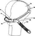
图1展示了本发明的一个实施例戴在人头上时的等距视图。Figure 1 shows an isometric view of one embodiment of the invention as it is placed on a human head.
图2展示了本发明的一个实施例的正视图,显示了根据本发明的一个实施例的总管、头部带组件、和连接到总管一侧的气源。Figure 2 illustrates a front view of one embodiment of the present invention showing the manifold, headgear assembly, and air supply connected to one side of the manifold in accordance with one embodiment of the present invention.
图3展示了本发明的一个实施例的俯视图。Figure 3 shows a top view of one embodiment of the invention.
图4展示了本发明的一个实施例戴在人头上时的右视图。Figure 4 shows a right side view of an embodiment of the present invention when worn on a human head.
图5展示了根据本发明的一个实施例的总管的一个实施例的俯视图。Figure 5 illustrates a top view of one embodiment of a manifold according to one embodiment of the invention.
图6展示了根据本发明的一个实施例的总管的一个实施例的正视图。Figure 6 illustrates a front view of one embodiment of a manifold according to one embodiment of the invention.
图7展示了根据本发明的一个实施例的总管的一个实施例的正视图。Figure 7 illustrates a front view of one embodiment of a manifold according to one embodiment of the invention.
图8A展示了根据本发明的一个实施例的总管的一个实施例的正视图。Figure 8A illustrates a front view of one embodiment of a manifold according to one embodiment of the invention.
图8B展示了根据本发明的一个实施例的总管的一个实施例的正视图。Figure 8B illustrates a front view of one embodiment of a manifold according to one embodiment of the invention.
图8C展示了根据本发明的一个实施例的总管的一个实施例的正视图。Figure 8C illustrates a front view of one embodiment of a manifold according to one embodiment of the invention.
图9A展示了根据本发明的一个实施例的总管的一个实施例的正视图。Figure 9A illustrates a front view of one embodiment of a manifold according to one embodiment of the invention.
图9B展示了图9A的总管的非圆形中间部分的横截面,其具有平直的上表面。Figure 9B shows a cross-section of the non-circular mid-section of the manifold of Figure 9A, with a flat upper surface.
图9C展示了图9A的总管的侧部分的圆形轮廓的横截面。Figure 9C illustrates a cross-section of the circular profile of the side portion of the manifold of Figure 9A.
图10A展示了根据本发明的一个实施例的总管的一个实施例的正视图。Figure 10A illustrates a front view of one embodiment of a manifold according to one embodiment of the invention.
图10B展示了图10A的总管的中间部分的横截面。Figure 10B shows a cross-section of the middle portion of the manifold of Figure 10A.
图10C展示了图10B的横截面附近的横截面。Figure 10C shows a cross-section adjacent to that of Figure 10B.
图10D展示了图10A的总管的纵截面。Figure 10D shows a longitudinal section of the manifold of Figure 10A.
图11展示了图10A的总管的中间部分的可替代横截面。Figure 11 illustrates an alternative cross-section of the middle portion of the manifold of Figure 10A.
图12A展示了根据本发明的一个实施例的总管的一个实施例的正视图。Figure 12A illustrates a front view of one embodiment of a manifold according to one embodiment of the invention.
图12B展示了通过图12A的总管的中间部分的横截面图。Figure 12B shows a cross-sectional view through the middle portion of the manifold of Figure 12A.
图12C展示了通过图12A的总管的侧部分的横截面图。Figure 12C illustrates a cross-sectional view through a side portion of the manifold of Figure 12A.
图13展示了根据本发明的一个实施例的总管的一个实施例的俯视图。Figure 13 illustrates a top view of one embodiment of a manifold according to one embodiment of the invention.
图14A展示了根据本发明的一个实施例的总管的一个实施例的俯视图。Figure 14A illustrates a top view of one embodiment of a manifold according to one embodiment of the invention.
图14B展示了根据本发明的一个实施例的总管的一个实施例的俯视图。Figure 14B illustrates a top view of one embodiment of a manifold according to one embodiment of the invention.
图14C展示了图14B的总管的横截面图。Figure 14C shows a cross-sectional view of the manifold of Figure 14B.
图14D展示了根据本发明的一个实施例的总管的一个实施例的俯视图。Figure 14D illustrates a top view of one embodiment of a manifold according to one embodiment of the invention.
图15A展示了根据本发明的一个实施例的总管的一个实施例的正视图。Figure 15A illustrates a front view of one embodiment of a manifold according to one embodiment of the invention.
图15B展示具有安装的鼻垫的图15A的凸起的横截面图。15B shows a cross-sectional view of the protrusion of FIG. 15A with the nose pads installed.
图15C展示了图15B的组件使用中紧密接触用户鼻孔时的横截面图。Figure 15C shows a cross-sectional view of the assembly of Figure 15B in use in close contact with a user's nostril.
图16A展示了根据本发明的一个实施例的鼻垫的一个实施例的侧视图。Figure 16A illustrates a side view of one embodiment of a nose pad according to one embodiment of the present invention.
图16B展示了图16A的鼻垫的俯视图。Figure 16B illustrates a top view of the nose pad of Figure 16A.
图16C展示了根据本发明的一个实施例的鼻垫的一个实施例的正视图。Figure 16C illustrates a front view of one embodiment of a nose pad according to one embodiment of the present invention.
图16D展示了根据本发明的一个实施例的鼻垫的一个实施例的正视图。Figure 16D illustrates a front view of one embodiment of a nose pad according to one embodiment of the present invention.
图17A展示了根据本发明的一个实施例的鼻垫的一个实施例的正视图。Figure 17A illustrates a front view of one embodiment of a nose pad according to one embodiment of the present invention.
图17B展示了具有膨胀的密封壁的图17A的鼻垫的正视图。17B illustrates a front view of the nose pad of FIG. 17A with expanded sealing walls.
图17C展示了图17B的鼻垫的横截面图。Figure 17C illustrates a cross-sectional view of the nose pad of Figure 17B.
图17D展示了图17C的一部分的详图。Figure 17D shows a detail view of a portion of Figure 17C.
图18A展示了根据本发明的一个实施例的鼻垫组件的一个实施例的正视图。Figure 18A illustrates a front view of one embodiment of a nose pad assembly according to one embodiment of the present invention.
图18B展示了根据本发明的一个实施例的鼻垫组件的一个实施例的正视图。Figure 18B illustrates a front view of one embodiment of a nose pad assembly according to one embodiment of the present invention.
图19展示了根据本发明的一个实施例的介于供气软管和总管之间的旋转弯管接头组件的一个实施例的正视图或者侧视图。Figure 19 illustrates a front or side view of one embodiment of a swivel elbow fitting assembly between an air supply hose and a manifold according to one embodiment of the present invention.
图20展示了根据本发明的一个实施例的用于连接头部带组件与总管的右连接组件的等距视图。Figure 20 illustrates an isometric view of the right connection assembly for connecting the headband assembly to the manifold in accordance with one embodiment of the present invention.
图21展示了根据本发明的一个实施例的头部带组件的一个实施例的等距视图。Figure 21 illustrates an isometric view of one embodiment of a headgear assembly in accordance with one embodiment of the present invention.
图22展示了根据本发明的一个实施例的头部带组件的一个实施例的右侧的侧视图。Figure 22 illustrates a side view of the right side of one embodiment of a headgear assembly according to one embodiment of the present invention.
图23A展示了根据本发明的一个实施例的总管端盖的一个实施例的正视图。Figure 23A illustrates a front view of one embodiment of a manifold end cap according to one embodiment of the present invention.
图23B展示图23的端盖的端视图。23B shows an end view of the end cap of FIG. 23 .
图23C展示了示意了斜面的图23B的端盖的横截面图。Figure 23C shows a cross-sectional view of the end cap of Figure 23B illustrating the bevel.
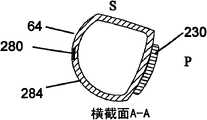
图24A展示了根据本发明的一个实施例的总管组件的一个实施例的正视图。Figure 24A illustrates a front view of one embodiment of a manifold assembly according to one embodiment of the present invention.
图24B展示了图24A在线A-A处的横截面。Figure 24B shows a cross-section of Figure 24A at line A-A.
图25展示了根据本发明的一个实施例的界面总管组件的一个实施例的俯视图。Figure 25 illustrates a top view of one embodiment of an interface manifold assembly according to one embodiment of the present invention.
图26展示了根据本发明的一个实施例的总管的一个实施例的俯视图。Figure 26 illustrates a top view of one embodiment of a manifold according to one embodiment of the invention.
具体实施方式Detailed ways
本发明提供了一种鼻枕无创通气装置。在某些实施例中,总管优选位于鼻子下方,它也可以称为″基础总管″。在某些优选实施例中,总管可以是低轮廓,并且在解剖学上可以与用户的面部一致或配合。通气气源优选可以在给定的任何时间从一侧连接到总管的仅一侧,并且在给定的任何时间通到脸的仅一侧,而不是从双向连接到总管的两侧,从而优选让用户感到极其舒服,不硌人,尤其是当用户侧睡时。此外,通气气源优选可以与可以在至少一个平面上旋转的旋转接头相连。总管和气源优选可以设计有曲线,以使用户的解剖学结构和位置与该装置在面部最舒服的部分上配合。低轮廓设计、气源单侧连接、旋转接头、以及曲线和形状的结合优选允许这一设计最不硌人,并且让用户舒服。另外,总管和气源优选可以被病人用介于头部带和总管之间的接头佩戴,该接头优选包括至少两个不同的调节,这样便于适应各人的头部形状和尺寸以及最大舒适度。The invention provides a nasal pillow non-invasive ventilation device. In certain embodiments, the manifold is preferably located under the nose, which may also be referred to as the "basic manifold". In certain preferred embodiments, the manifold may be low profile and may anatomically conform or fit the user's face. The source of ventilation air is preferably connectable from one side to only one side of the manifold at any given time, and to only one side of the face at any given time, rather than bi-directionally connected to both sides of the manifold, thus preferably It makes the user feel extremely comfortable and not uncomfortable, especially when the user sleeps on the side. Furthermore, the ventilation gas source can preferably be connected to a swivel joint which can be rotated in at least one plane. The manifold and air source can preferably be designed with curves to fit the user's anatomy and position with the device on the most comfortable part of the face. The low profile design, one-sided connection to the air supply, swivel joints, and combination of curves and shapes are preferred to allow this design to be the least intrusive and comfortable for the user. In addition, the manifold and air source are preferably wearable by the patient with a joint between the head strap and the manifold, which preferably includes at least two different adjustments, so as to facilitate adaptation to the shape and size of the individual's head and maximum comfort .
图1展示了根据本发明的一个实施例的通气界面组件的实施例的等距视图,该组件固定在人(也可以称为病人或用户,Pt)的面部和头部。通气界面组件50包括头部带组件80、位于鼻子N下方的弓形复合总管60、单侧连接到总管60仅一侧并且仅配置在人脸一侧的通气供给组件120、以及从总管向上延伸至紧密接触、进入人的鼻孔并且优选与人的鼻孔形成密封的两个鼻垫70。鼻垫也可以称为鼻密封垫。供气组件120与呼吸器(未显示)相连,用于将气道正压力供应给人的鼻子和气道。总管60可以优选设计有复合弓形曲线,该曲线优选与人的解剖学结构达到最佳和舒服的配合,以增加舒适度,并且当用头部带组件捆扎在适当位置上时,有助于使总管在面部保持稳定。鼻垫70优选可以设计有如下特征:它们能在鼻孔的边缘周围施加轻且宽大、但又有效的密封力。鼻垫70可以永远地或可拆卸地连接到总管。总管60和供气组件120优选可以如此设计,即让气流的湍流最小,从而产生低压降设计,这优选提高密封效力,并且降低噪音和泄漏。例如,因为从气源出来的气流优选在任意给定的时间仅从一侧进入总管,所以更好地避免了与同时从两侧进入总管、软管或套管内的气流有关的气体的湍流碰撞。头部带组件80优选可以设计有如下特征、调节器和材料:为用户提供可靠、但柔软、舒服且形状完全一致的配合。总管60和头部带组件80优选具有能让任意给定的用户将该结构放在他们的面部和头部的最舒服且不硌人的部分上的形状。整个组件优选具有允许用户以各种姿势舒服地睡觉,而不会造成面罩移位和故障的功能。用户优选可以用他们的与供气连接件相反的那一侧脸自由入睡。另外,用户优选可以用与供气连接件所连接的那一侧脸自由入睡,例如通过向下旋转供气组件。除了优选在任何睡姿都舒服且密封有效外,本发明的通气界面组件的优选实施例优选对用户造成的不便和麻烦最小,因为通气界面组件优选可以被如此定位得使该组件离用户的眼睛、耳朵和嘴相对较远,并且供气组件120完全离开面部的一侧。因为本发明的优选实施例优选允许病人睡得舒服,没有不便,病人优选能容忍并服从他或她建议的气道正压力(PAP)治疗,因此与使用其他气道正压力通气界面装置相比,医疗可以更有效。对于其他气道正压力通气界面装置,已经证明病人对治疗的耐受性和适应性差,因为该界面装置太不舒服或者太硌人,并且病人不按建议使用它,因此疗效本质仍然很差,乃至不曾治疗。因此可以看到本发明的优选实施例优选解决了气道正压力界面装置的许多以前未解决的问题,尤其是用于治疗阻塞性睡眠呼吸暂停(OSA)的那些气道正压力界面装置。Figure 1 illustrates an isometric view of an embodiment of a ventilation interface assembly secured to the face and head of a person (also referred to as a patient or user, Pt) in accordance with an embodiment of the present invention. The
总管的各种实施例被归入本发明的实施例。优选,根据本发明的一个实施例的通气界面组件具有不止一种类型和/或尺寸,以使每个用户都可以选择佩戴舒服的总管。作为另一优选的替换方式,临床医生可以为用户佩戴一个或多个佩戴舒服的适当的总管。作为一个非限定性的实例,用户可以发现轴向弧长长于他们鼻子根部的宽度的总管最舒服。同样,鼻垫的各种实施例被归入本发明的实施例。优选,根据本发明的一个实施例的通气界面组件具有不止一种类型和/或尺寸与所提供的总管适合,以使每个用户都可以选择佩戴舒服的鼻垫。作为另一优选的替换方式,临床医生可以为用户佩戴适当的佩戴舒服且与为病人提供的总管相适合的鼻垫。Various embodiments of the manifold are included as embodiments of the invention. Preferably, a ventilation interface assembly according to an embodiment of the present invention is available in more than one type and/or size so that each user can choose a manifold that is comfortable to wear. As another preferred alternative, the clinician may wear one or more suitable manifolds that are comfortable to wear for the user. As a non-limiting example, users may find most comfortable a manifold with an axial arc length longer than the width at the base of their nose. Likewise, various embodiments of nose pads are included as embodiments of the present invention. Preferably, a ventilation interface assembly according to an embodiment of the present invention has more than one type and/or size to fit the manifold provided so that each user can choose a nose pad that is comfortable to wear. As another preferred alternative, the clinician may wear appropriate nasal pads for the user that are comfortable to wear and that fit the manifold provided to the patient.
图2展示了本发明的一个实施例的通气界面组件50的一个实施例的正面或者冠状面(CP)视图。供气组件120包括软管140、连接到呼吸器或者通气输送回路上的近端供气接头130、和优选将供气组件120连接到总管60的远端旋转弯管接头组件90。呼吸器或者通气输送回路没有显示。关于本发明的这一以及其他实施例,可以使用任何合适的呼吸器或者气体输送回路。在整个说明书中,术语远端和近端是相对的位置术语,其中近端是指距呼吸器或者通气回路相对较近的位置,而远端是指距呼吸器或者通气回路相对较远的位置。用″A″来指总管的前侧,尤其是在附图中。用″P″来指总管的后侧,尤其是在附图中。用″S″来指总管的顶侧/上侧,尤其是在附图中。用″I″来指总管的底侧/下侧,尤其是在附图中。旋转弯管接头组件90优选可用于被用户将供气组件120旋转或者回转到最希望的位置。总管60的与旋转弯管接头组件90相对的侧面优选用端盖100来封闭。总管60、旋转弯管接头组件90和端盖100优选如此配置以使临床医生或者病人可以切换与旋转弯管接头组件90和端盖100中的每个相连的总管60的那一个侧面。作为另一个优选的替换实施例,可以为临床医生或者病人提供包含至少两个总管的成套组件:一个的旋转弯管接头组件90在左,端盖100在右,而另一个的旋转弯管接头组件90在右,端盖100在左。总管60优选被头部带组件80固定在合适的位置;头部带组件80和总管60优选与左、右互连组件110’、110连接在一起,该左、右互连组件110’、110优选构造和/或组装成允许在头部带组件80和总管60之间有可移动的或者可调节的连接,以使通气界面组件优选可以被最佳调节到适合各个用户。当然,总管60、端盖100和/或供气组件120以及总管和接头组件的其他实施例可以与其他装置一起使用以将它们紧固到病人的头上、脸上和/或鼻子上。Figure 2 illustrates a front or coronal (CP) view of one embodiment of a
图3用俯视图或者横剖面TP图展示了本发明的一个实施例的通气界面组件50的一个实施例。左、右互连组件110’、110,优选每个都包括左和右总管连接环200’、200、左和右头部带连接板202’、202和连接板护皮垫204’、204。在所示的总管的实施例中,显示了总管的复合弓形曲线的后方扫略曲线,它优选帮助将总管基部60舒服地且有效地定位在脸上。FIG. 3 illustrates an embodiment of a
图4展示了人Pt戴着的病人通气界面组件50的一个实施例的右侧或者矢状面(SP)视图,比较详细地显示了头部带组件80的一个实施例中的元件。头部带组件80包括左和右前头部带219’、219(左前头部带219’未显示)和至少一条具有后带扣214的后带221,以及可选择地具有顶带扣215的顶头部带223,以及左和右头部带-总管接头217’、217(左头部带-总管接头217’未显示)。优选每条前头部带219’、219都包括软织物或者弹性带材210’、210和加强构件212’、212(左侧带材210’和加强构件212’未显示)。在一个优选实施例中,头部带组件80和总管60之间的接头217’、217(左侧接头217’未显示)是可调节的。前带的加强构件212’、212和头部带连接板202’、202可以用配合元件上的孔和突起连接来互连。例如,可以在加强构件212’、212的前端附近设置一个孔,可以在连接板202’、202的后端附近设置一个有倒钩的突起,这样,加强构件212’、212会卡在连接板202’、202上。作为另一个实例,可以在加强构件212’、212上设置有倒钩的突起,而在连接板202’、202上设置配合孔,这样,连接板202’、202会卡在加强构件212’、212上方的适当的位置。孔和突起连接优选提供旋转或者枢转以允许该接头枢转,优选允许整个通气界面组件50被配置和调节成与个人的解剖学结构配合良好。另外,孔和突起连接可以包括多个离散的设置点,以便用户或者照料人员可以根据需要调节接头的角度。在这种情况下,可以在连接板202’、202和加强构件212’、212上设置一系列通道、肋条或者键槽,以制造不同角度的设置。加强构件212’、212和连接板202’、202优选可以由半刚性的热塑性材料构成,例如尿烷、聚氯乙烯、聚乙烯、聚丙烯或者聚砜,从而为接头提供较好的机械强度。对于连接张力,接头强度优选可以为0.1-0.5磅,而对于由病人体重施加于接头上的经受压力,高达10磅。在此描述有关这些元件以及包括在本发明的某些实施例中的其他类型的接头的更多细节。FIG. 4 illustrates a right side or sagittal (SP) view of one embodiment of patient
图5-15更详细地展示了根据本发明的某些实施例的总管的实施例。5-15 illustrate embodiments of manifolds in greater detail, according to some embodiments of the invention.
图5展示了沿总管60的横剖面的等轴测俯视图。在该实施例中,总管的形状从中线向侧部以向侧部-向后的扫略曲线260弯曲,从而优选与鼻子下方的脸的形状相配合,并且如其它视图所示的那样,还优选向上弯曲。总管优选包括用于安装鼻垫的安装缘240和气流开口236,该安装缘优选可以是可拆卸地安装,该气流开口允许通气气体通过鼻垫。鼻垫也可以被永久地安装到总管60上,或者安装到安装缘240上,后者通过其他方式。图5还展示了总管连接环安装孔244,用于总管-头部带安装连接环200’、200(未显示)的配合和固定,并用于连接端盖或者供气组件。可选择地,总管60可以包括位于后部皮肤侧面上的护皮垫230,它可以优选帮助倾斜总管的角度到矢状平面中的适当角度,以便在安装鼻垫时鼻垫与鼻孔的角度一致。如果设置的话,垫230还可以吸收带子的勒力。FIG. 5 shows a top isometric view along a cross-section of the manifold 60 . In this embodiment, the shape of the manifold curves laterally from the midline in a lateral-
总管的向侧部-向后的曲线260的半径优选为1.0-5.0″,成人尺寸更优选为2.0-4.0″,儿童尺寸为1.0-2.0″,新生儿尺寸为0.5-1.0″。总管60可以具有若干横截面外部尺寸,例如,非限定性实例:小号为12-16mm,中号为14-18mm,大号为16-20mm,特小号为10-14mm,而特大号为18-22mm。总管60可以具有至少三个左右长度尺寸,例如,非限定性实例:大号为3-2.5英寸,中号为2.5-2英寸,小号为2-1英寸。总管60可以优选由例如硅树脂、尿烷、Santropene的弹性体或者例如尿烷-聚氯乙烯混合物的弹性体混合物或者C-Flex构成。总管60还可以用热塑性弹性体或者增塑的热塑性塑料制成。总管60的材料的邵氏硬度优选为40-60A,它的壁厚优选为0.040-0.120″。总管60还可以用可以由护理人员或者最终用户再成形或者再成型的材料制成,以便与最终用户的解剖学结构更好地配合。总管60的再成型还可以通过如下方式来实现:通过用例如PVA的可以受热和再成形的热固性材料制造,或者通过将可延展元件包括在总管的结构内,以便病人或者临床医生能将它弯曲成想要的形状,这在随后描述。The lateral-
图6展示了图5的总管60的正视图,其中鼻垫70连接到总管60上。总管60包括向侧部-向上的扫略曲线262,它在侧端附近趋向于侧向扫略曲线264。向侧部-向上的曲线的半径优选为1.0-3.0″,成人尺寸更优选为1.5-2.5″。曲线262和264优选与后扫略曲线260(在其他视图中显示,例如图5)复合。这种复合弓形曲线优选允许总管与面部的解剖学结构最佳配合,例如避免遮挡住嘴,并且避免被放在不舒服的面部结构处,例如颊骨和颌骨处。另外,这些曲线可用于使鼻垫的远端在冠状面中向内倾斜。两鼻垫70之间的角度b优选为20-60度,更优选为30-50度,越发优选为36-48度;两鼻垫的密封面267之间的间距268优选为0-7mm,更优选为2-5mm。然而,鼻垫的安装、间距和角度的其他选择也是可以的,并且包括在本发明的某些实施例中。例如,鼻垫也可以包括弯曲特征,以允许它们弯曲和压缩,这在下面更详细地说明。图6还展示了总管安装环槽274和总管连接环安装孔278,用于总管-头部带安装连接环200’、200(未显示)的配合和安装,和用于连接端盖或者供气组件。该槽优选允许安装连接环200’、200与总管相连,且表面平齐。该槽优选为0.030-0.090″深和0.080-0.250″宽。FIG. 6 illustrates a front view of the
图7展示了根据本发明的一个实施例的总管的一个替换实施例的正视图。在图7中,总管61包括总管左和右两侧的复合弓形曲线,其中复合弓形曲线包括向侧部-向上的第一曲线262,它从总管中线263向两侧延伸,并过渡到延伸到总管侧端的向侧部-向后-向下的第二曲线265。还展示了可以随意地和根据本发明的一个实施例的总管一起使用的一些其他的特征。Figure 7 illustrates a front view of an alternate embodiment of a manifold according to an embodiment of the present invention. In FIG. 7, the manifold 61 includes compound arcuate curves on the left and right sides of the manifold, wherein the compound arcuate curve includes a sideways-upward
图7展示了可选择的呼气排气口270。在图7的实施例中,呼气排气口270为两组通过总管下壁的多个孔,这些孔如此定位,即每一组都与一个鼻垫75大致相对,以便呼气排气口270与通过鼻垫的呼出流的方向一致,并且与从左侧或右侧流入总管并向上流入鼻垫的吸入流的方向不一致。因此,通过呼气排气口270的呼气优选可以相对容易,并且在吸气过程中,通过呼气排气口270的漏失量优选可以相对较少。每个呼气排气口270的直径优选为0.5-3.0mm,各呼气排气口270合起来的总横截面积优选为50-225mm2。呼气排气口的总阻力为2-20cmH2O/L/sec。呼气排气口270位于总管内侧的入口优选可以倒角,以减小气流通过这些排气口从总管内部排出的阻力。呼气排气口270的图案可以选择模仿鼻孔的形状,以便排出的气体近似于通过鼻子呼气而产生的流动图案。呼气排气口270可以选择定向在通过总管壁的对角线上,在总管内侧定向成更紧密的,并且在总管的侧部成扇形散开成更大的图案,以便排出的气体类似于从鼻子中呼出的一样成扇形散开。可选择地,呼气排气口可以具有单向阀特征,以允许沿呼气方向流动,但限制沿吸气方向流动。呼气排气口可以可选择地放在其他位置和设置成其他图案,例如,举一些非限定性的例子,横跨总管的整个下表面,在总管下表面的中部,或者在总管的从一个鼻垫下方的位置到另一个鼻垫下方的位置的下表面上,或这些位置的组合。呼气排气口可以具有圆形的横断面形状或者其他横断面形状,例如卵形、三角形、或者矩形。FIG. 7 illustrates an alternative
图7还展示了总管安装环槽274和连接环安装孔278,用于总管-头部带连接环200’、200的配合和安装。该槽优选允许连接环200’、200与总管相连,且表面平齐。该槽优选为0.030-0.090″深和0.080-0.250″宽。可选择地,连接环可以永久固定到总管上,而不是可拆卸地连接。在后一个例子中,连接环可以粘合到总管上,或者总管可以模制在连接环的周围。图7还展示了一个可选择的实施例,其中鼻垫75可以预先安装或者永久固定到总管上,通过粘合到总管上,或者与总管一起模制。Fig. 7 also shows the header
图8A-8C展示了总管的复合弓形曲线的替代实施例,其中总管向侧部、向后、和向下弯曲。图8A展示了总管62的正视图,其中总管包括具有扫略到总管的左和右侧端的左和右向侧部-向后-向上的曲线292和向侧部-向后-向下的曲线290的复合弓形曲线。曲线292的半径优选为3.0″-8.0″,更优选为4.0″-6.0″。该形状优选使总管定位于脸的柔软结构、鼻子两侧,最优选为颊骨和颌骨之间,并且优选帮助鼻垫70向内朝向中线倾斜,从而与鼻孔的解剖学结构配合。可选择地,位于中线263附近的总管中心可以包括向下曲线。向侧部-向后-向上的曲线292的上部可以是明显的曲线,例如1.0-3.0″的半径,或者可以是平缓的曲线,例如3.0-5.0″的半径。可替代地,这一部分也可以是直的,或者具有向上的曲线,可以是倾斜的,或者是它们的组合。图8B展示了几何形状类似于图8A中的总管的可替代总管;总管62’包括中线附近冠状平面内的平直表面。图8B还展示了一个可替代实施例,其中凸起323附接于总管62’的上表面;鼻垫可以安装到凸起。凸起可以包括连接环或者脊325,便于可靠地安装鼻垫。凸起和/或鼻垫优选可以相对于总管上表面倾斜,以便于鼻垫在冠状面中适当倾斜,从而与鼻孔的角度配合。凸起和/或鼻垫还可以可选择地在矢状面中倾斜,以便于鼻垫在矢状面中适当倾斜,从而与鼻孔的角度配合。有关鼻垫凸起的其他可选择的细节见图15A。图8C展示了在图8B中描绘的总管形状的可替代实施例,其中总管62″包括向侧部-向后曲线(图中未显示)和向侧部-向下的斜线而非曲线。向侧部-向下的角度j可以优选为25-75度,更优选为40-60度。在图8C所示的实施例中,总管中间部分的上表面被显示为平直表面,上面带有安装圈240。在这一实施例中,鼻垫可以优选适合于安装在安装圈240上,并且安装圈240可以可选择地成形为让鼻垫的末梢向内朝向中线倾斜,例如图16C所示。Figures 8A-8C illustrate an alternate embodiment of the compound arcuate curve of the manifold, where the manifold curves sideways, rearward, and downward. 8A shows a front view of the manifold 62, wherein the manifold includes left and right side-back-up curves 292 and side-back-down curves with sweeping to the left and right side ends of the manifold. 290's compound bow curve. The radius of curve 292 is preferably 3.0"-8.0", more preferably 4.0"-6.0". This shape preferably positions the manifold between the soft structures of the face, the sides of the nose, most preferably between the cheekbones and the jaw, and preferably helps the
图9A-9C展示了包括变截面和加强构件的总管63的可替代实施例的正视图和截面图。图9B展示了在图9A的线A-A处通过总管中间部分的横截面。前后轴线上的横截面尺寸可以短于上下方向上的尺寸,这可以减小总管从用户面部突出的轮廓。总管的上表面S的弯曲可以变平,这可以为鼻密封垫的安装提供较平的连接表面。图9C展示了在总管侧端附近的线B-B处的总管63的横截面轮廓,它可以基本上是圆形,这可以让圆形接头或者端盖合适地安装到总管的端部。作为另一个非限定性的可替代方案,非圆形横面几何形状可以继续贯穿总管的长度延续到总管端部,并且在将刚性的圆形接头连接到总管上时,由于优选的总管材料的硅橡胶性质,因此总管材料可以密接到刚性材料上。总管还可能包括如下描述的其他特征,其他特征例如鼻垫可以安装于其上的安装圈240、供气体通往鼻垫(未显示)的气流开口236,以及连接环连接特征。9A-9C illustrate front and cross-sectional views of an alternative embodiment of a manifold 63 including variable sections and stiffening members. Figure 9B shows a cross-section through the middle portion of the manifold at line A-A of Figure 9A. The cross-sectional dimension in the front-rear axis may be shorter than in the up-down direction, which may reduce the protruding profile of the manifold from the user's face. The curvature of the upper surface S of the manifold can be flattened, which can provide a flatter connection surface for nose seal installation. Figure 9C shows the cross-sectional profile of the manifold 63 at line B-B near the side ends of the manifold, which may be substantially circular, which allows for proper fitting of circular fittings or end caps to the ends of the manifold. As another non-limiting alternative, the non-circular cross-sectional geometry may continue throughout the length of the manifold to the ends of the manifold and when rigid circular joints are attached to the manifold, due to the preferred manifold material Silicone rubber properties, so the header material can be bonded to the rigid material. The manifold may also include other features as described below, such as mounting
图9A和9B还展示了一个可选择的加强构件280,它可以安装于总管63的前(A)壁。加强构件280优选可以放在前壁的内侧,例如在模制总管的过程中;然而,可替代地,它还可以放在外壁上、内壁上、或者其他壁上,例如下壁、上壁或者后壁。总管63可以可选择地包括多个加强构件。作为一个非限定性的例子,加强构件280可以是材料条,厚度优选为0.005″-0.030″,更优选为0.010″-0.020″,并且宽度优选为0.040″-0.200″,更优选为0.060″-0.130″。加强构件280可以拥有矩形的、卵形的、圆形的、直的或者弯曲的横截面。加强构件280优选可以由可延展材料构成,例如黄铜、铜或者镍合金,其优选可以通过用户或者临床医生制成一定形状以调节总管的复合曲率,这样总管可以被进一步定做,以与个人的解剖学结构配合。作为其他非限定性的可替代方案,加强构件可以由形状记忆材料构成,例如铝合金、诸如ULTEM之类的热塑性树脂、或者弹簧钢、或者诸如镍钛金属互化物的形状记忆金属。作为另一个可替代方案,总管可以通过骨架或者热塑性撑杆的超结构来加强,在此情况下,总管可以例如通过两步法模制工艺来制造:第一步,模制热塑性骨架,第二步,在骨架周围模制硅橡胶材料。举例来说,骨架可以由热塑性塑料构成,例如聚丙烯、聚砜、尼龙或者Ultem;而周围材料可以由弹性体构成,例如硅树脂、尿烷或者Santropene。骨架优选占总管材料总体积的10-25%,而周围的弹性体优选包括其余的材料体积。FIGS. 9A and 9B also illustrate an
图10A-10D展示了根据本发明的一个实施例的总管的可替代实施例,其中总管64包括非圆形中心横截面和位于横截面轮廓内的加强肋。图10A展示了具有复合弓形曲线的总管64的正视图,其中复合弓形曲线包括向侧部-向上的曲线和向侧部-向下的曲线。然而,这些曲线是示范性的,其他复合弓形或者倾斜的曲线,例如在本说明书其他地方描述的,也被归入这一实施例。图10B展示了通过图10A中所示的总管的中线263处或其附近的线A-A处的前后平面的横截面,并且显示了总管的横截面轮廓和总管壁284的几何形状。该横截面表示总管的后(P)壁可以以角度a倾斜,而总管的上(S)壁可以以角度a’倾斜。角a优选与用户的鼻子和嘴之间的面部的解剖学角度配合,而角a’形成了倾斜的上表面,它优选便于更好地定位鼻垫,优选从总管上表面伸出的鼻垫在矢状面中倾斜,以便它们与鼻孔的角度一致。总管侧端处或其附近的横截面优选基本上呈圆形(未显示),从而便于方便地安装到如下所述的圆插头或者供气软管接头上。因此,总管横截面优选可以从总管中间部分的非圆形横截面轮廓过渡到端部的大致圆形的横截面。10A-10D illustrate an alternative embodiment of a manifold in accordance with one embodiment of the present invention, wherein the manifold 64 includes a non-circular central cross-section and stiffening ribs located within the cross-sectional profile. FIG. 10A illustrates a front view of a manifold 64 having a compound arcuate curve including a side-up curve and a side-down curve. However, these curves are exemplary and other compound arcuate or oblique curves, such as described elsewhere in this specification, are also contemplated in this embodiment. 10B illustrates a cross-section through the anterior-posterior plane at line A-A at or near the
可选择地,如图11所示,护皮垫230可以被安装于总管的后侧。图11展示了图10A中的总管中间部分的可替代横截面,展示了安装于总管后侧的可选择的护皮垫。护皮垫230优选可以帮助控制角度a,帮助吸收由优选用于将总管紧固到面部的头部带组件施加的勒力。角度控制可以通过护皮垫的形状或者护皮垫材料的可压缩性来实现。护皮垫230可以是可拆卸的或者固定的,并且可以优选由可压缩的形状记忆材料构成,诸如粘弹性材料,例如形状记忆泡沫,或者硅树脂凝胶。护皮垫可以可拆卸地安装于总管,或者可以是总管材料的延伸。在某些实施例中,例如在护皮垫可拆卸的实施例中,可以为临床医生或者用户提供多个护皮垫。多个护皮垫可以有不同的形状、尺寸和可压缩性,优选可以允许用户选择最舒服的护皮垫。多个护皮垫可以有相同的形状、尺寸和可压缩性,如果护皮垫弄脏或者被磨损,优选可以允许用户更换护皮垫。Alternatively, as shown in FIG. 11 , a
图10C展示了图10A中所示的总管的中线附近的线A’-A’处的横截面,它朝向一个侧端与横截面A-A隔开一定距离,其中由于总管内壁上存在径向加强肋310,因此在该位置上总管壁284可以被加厚。图10D展示了图10A中显示的总管在线B-B处的从左到右横截面,它显示了多个径向肋310。在整个或者部分总管长度上,这些径向加强肋可以均匀地隔开或者采用一个图案。肋310优选加强总管,它优选由柔软的材料制成,优选为弹性体材料。因此肋310优选阻挡总管结构变扁或者压缩,同时仍然保持总管柔软和舒服。肋310优选从总管的内表面向内突出,高度优选为0.040-0.100″,宽度优选为0.030-0.125。肋之间的间隔优选为0.25-0.75″。Figure 10C shows a cross-section at line A'-A' near the center line of the manifold shown in Figure 10A, which is spaced from cross-section A-A towards one side end, where due to the presence of radial stiffening ribs on the inner wall of the manifold 310, so that the
图12A-12C展示了根据本发明的一个实施例的总管64’的一个可替代实施例,其中轴向或者纵向的加强肋314设置在总管的壁结构中。这些轴向肋314可以在整个或者部分总管壁上均匀间隔或者采用一种图案。轴向肋314可以可选择与径向肋310结合使用。图12B展示了图12A中显示的线A-A处的总管中线附近的横截面。该横截面显示了构造到总管64’的壁284上的轴向肋314的图案。图12B还展示了总管的非圆形横截面,它优选便于与病人的面部的角度配合,并校准鼻垫到鼻孔的角度。图12C展示了图12A中的总管的侧端附近线B-B处的带有肋314的横截面。图12B中展示的非圆形横截面优选过渡到如图12C所示的大致圆形的横截面。大致圆形的横截面优选便于连接到总管端盖或者供气接头。可选择地,这些肋可以在总管的侧端附近中断,从而提供平滑的圆形表面,以与总管端盖和供气接头配合;作为另一个非限定性的可替代方案,这些肋可以继续排列至总管侧端,并且端盖和供气接头可以具有带有凹槽的配合几何形状,从而与带肋总管的几何形状对准并滑入其中。一条肋或者这些肋还可以沿着总管的长度是断断续续的,带肋段与平滑段交替。相比于图10A-10D中显示的径向肋,图12A-12C可以更优选,因为轴向肋几乎不对总管内的层状气流分布造成干扰。轴向肋的高度优选为0.040-0.100″,宽度优选为0.030-0.125″,间隔优选为20-45度。Figures 12A-12C illustrate an alternative embodiment of a manifold 64' in which axial or
图13展示了根据本发明的一个实施例的总管的一个实施例的俯视图,其中总管60’类似于图5的总管,包括从中线263扫略至左和右侧端的左和右向侧部-向后的曲线260。气流开口236之间、中线263附近的中间部分可以包括如图所示的直边段,或者可替代地,左和右向侧部-向后的曲线260可以起始于中线并且包括中线。在图13的总管60’中,与远端处的总管宽度相比,中线附近的总管中间部分在前后尺寸上较窄;这种形状优选减小总管的轮廓和鼻子下方的突出。可替代地,总管中间部分的前后尺寸可以较宽,从而便于适应鼻垫的安装,而在鼻子侧部较窄;这一形状优选减小鼻子侧部的轮廓和突出。Figure 13 illustrates a top view of one embodiment of a manifold in accordance with one embodiment of the present invention, wherein the manifold 60' is similar to that of Figure 5, including left and right sides swept from the
图14A展示了一个可选择的实施例的俯视图,其中总管为具有左部分65’和右部分65的两件式总管,总管中心连接环320相互连接总管部分65’和65。总管中心连接环320优选允许用户或者临床医生调节组装好的总管的全长,以便在安装鼻垫时,鼻垫的间隔能更精密地配合用户鼻孔的间隔。举例来说,总管中心连接环320可能包括左和右配合部分,它们通过很轻的过盈配合配合在一起,其中这两个部分可以彼此滑入和滑出,以调节两件式环的长度。这两个部分可以包括配合的锁定特征,从而设定多个位置并且阻挡无意的调节。其他的长度可调节的总管中心连接环可以考虑,并且可以与本发明的各实施例一起使用。非限定性的例子包括由左和右配合部分构成的总管中心连接环和一个单件式接头,该左和右配合部分扭在一起,以改变长度,其中总管左侧部分65’和总管右侧部分65可以在接头上可滑动地移动。在制造过程中,或者在分配给最终用户的过程中,左和右总管部分65’、65可以不可拆卸地附接于总管中心连接环的左和右端部,因此需要最终用户组装的较少。在这些实施例中,可以通过调节总管中心连接环的长度来调节总管组件的全长。可替代地,总管中心连接环可以可调节地附接于左和右总管部分65’、65中的其中一个或者每一个上,并且可以通过调节左和/或右总管部分65’、65和总管中心连接环之间连接的接合长度来调节总管组件的全长。在这些实施例中,总管中心连接环的长度本身可以是不可调节的或者可调节的。可替代地,可以提供多个尺寸和长度的总管中心连接环,以便用户可以选择更好的尺寸和长度。如果提供多个尺寸的总管中心连接环,它们本身可以具有可调节的或者不可调节的的长度,并且可以被可调节地或者不可调节地连接到总管部分65’、65。连接环优选由热塑性塑料构成,例如聚丙烯,聚乙烯,聚砜,尼龙或者聚氯乙烯。可选择地,连接环的外径可以包括覆盖的弹性体,从而为用户提供软接触。Figure 14A shows a top view of an alternative embodiment in which the manifold is a two-piece manifold having a left portion 65' The manifold center connection ring 320 preferably allows the user or clinician to adjust the overall length of the assembled manifold so that when the nasal pads are installed, the spacing of the nasal pads can more closely match the spacing of the user's nostrils. As an example, the manifold center connection ring 320 may include left and right mating sections that fit together with a very light interference fit, where the two sections can slide in and out of each other to adjust the length of the two-piece ring . The two parts may include cooperating locking features to set multiple positions and block inadvertent adjustment. Other adjustable length manifold center connection rings are contemplated and may be used with various embodiments of the present invention. Non-limiting examples include a manifold center connection ring formed of left and right mating portions that are twisted together to vary in length, wherein the manifold left portion 65' and the
图14B展示了一个可选择的两件式总管实施例的俯视图。左和右总管部分65’,65通过总管中心连接元件321相连,总管中心连接元件321优选执行以下两个功能中的一个或者两个。第一,连接元件321优选可用以调节鼻密封垫之间的距离,以便该距离更精密地配合个人用户的鼻孔。第二,连接元件优选包括结构化连接元件撑杆322,它优选延伸到总管部分65’、65的内部,从而优选为总管提供结构刚度,总管优选由柔韧的材料制成。图14C展示了通过图14B的总管组件的横截面,显示了连接元件321、连接元件骨架撑杆322、和总管65。连接元件321优选延伸到总管里足够远,从而在总管里实现例如0.100-0.200″深的密封。连接元件321优选由热塑性塑料构成,例如聚丙烯、聚乙烯、聚砜、尼龙或者聚氯乙烯。环部分321优选厚0.020-0.080″;撑杆322优选厚0.015-0.050″,宽0.040-0.120″,长0.5-1.5″,间隔以20-45度递增。一个装置可以包括长度变化的撑杆322。Figure 14B shows a top view of an alternative two-piece manifold embodiment. The left and
图14D展示了根据本发明的一个实施例的总管的一个可替代实施例。在图14D的总管中,左和右总管部分66’、66互相不对称。一侧被构造成锥形闭合,另一侧被构造成用于安装旋转弯管接头组件90。如图所示,中心连接元件321可用于可拆卸地安装左和右总管部分。通过使用连接元件321,供气连接件的安装侧可以变化。可替代地,可以使用中心连接环320,或者总管可以采用单件式。可以为临床医生或者用户提供成套组件,该成套组件包括一个封闭一个打开的两个左侧部分,以及一个封闭一个打开的两个右侧部分。可替代的成套组件(或者同一个成套组件)可以包括右端封闭的单件式总管和左端封闭的单件式总管。此外,可以提供多个直径和长度尺寸的总管部分66’、66,从而为临床医生或者最终用户提供另外的配合范围选择。Figure 14D illustrates an alternate embodiment of a manifold according to an embodiment of the present invention. In the manifold of Figure 14D, the left and right manifold sections 66', 66 are asymmetrical to each other. One side is configured for conical closure and the other side is configured for mounting a swivel elbow
图15A展示了根据本发明的一个实施例的总管的一个可替代实施例。在图15A中,总管62″包括突出的安装凸起324,用于安装鼻垫。在图15B和15C显示的非限定性的例子中,鼻垫优选可以可拆卸地安装于安装凸起。举例来说,该凸起可以延伸到鼻垫长度的50%;和/或如图所示,可以包括延伸到接近鼻垫全长的伸出部327。凸起或者凸起伸出部优选比鼻垫更硬,因此凸起或者凸起伸出部为鼻垫提供结构框架或者支撑。鼻垫优选可以极其柔软,并且适合于接触、符合和密封鼻孔表面,而不施加不舒服的力。举例来说,在0.05-1.0磅的径向力下,更优选在0.1-0.5磅的径向力下,安装凸起或者伸出部可以优选具有径向压缩的50%的抗压强度。在某些使用凸起324的实施例中,鼻垫可以优选由比不用凸起时更软的材料构成。举例来说,鼻垫的邵氏硬度可以为10-50A,尤其是如果和凸起一起使用时。这些非常软的鼻垫也可以称为″鼻垫套筒″,并且优选与凸起一起使用;同样凸起也优选与鼻垫套筒一起使用。举例来说,鼻垫还可以是非常易压缩的,尤其是如果和凸起一起使用时;举例来说,使用0.05-0.25磅的径向力,鼻垫的壁厚优选可以径向压缩50%。鼻垫优选可以由具有快速尺寸恢复性质的粘弹性材料构成,一个非限定性的例子是能在小于3秒内从25%的压缩恢复80%以上的形状记忆泡沫。图15B展示了通过示范型鼻垫76的横截面,鼻垫的宽度尺寸优选比密封尺寸大10-50%,更优选大20-30%,例如6mm-30mm宽。图15C展示了使用中的图15B的鼻垫,显示密封区域压缩到密封尺寸,以符合鼻孔的解剖学结构。鼻垫和鼻垫凸起可以包括配合特征,它可以防止鼻垫无意中与凸起分开,或者减少这种可能性。这种配合特征的一个非限定性的例子是凸起上的保持圈325,例如在图15A-15C中展示的。这种配合特征的另一个非限定性的例子是凸起上的凹槽和与凸起上的凹槽接合的鼻垫上的突起或者张力环。图15A还显示了位于安装凸起324根部的一个可选择的弯曲特征。该弯曲特征优选包括垫座326和凹槽323,它们优选允许鼻垫侧向弯曲、前后弯曲、和/或上下压缩。这种弯曲能力优选允许鼻垫弯曲和移动以(a)允许小幅校准调节,以便鼻垫更恰当并且舒服地与鼻孔配合,和(b)当用户在使用过程中移动头部而导致通气界面组件轻微移位时,便于保持与鼻孔接触。Figure 15A illustrates an alternative embodiment of a manifold according to an embodiment of the present invention. In FIG. 15A, the manifold 62″ includes protruding mounting
图16A-18B更详细地展示了根据本发明的某些实施例的鼻垫的某些实施例。16A-18B illustrate in greater detail certain embodiments of nose pads according to certain embodiments of the present invention.
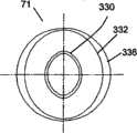
图16A和16B展示了根据本发明的一个实施例的鼻垫的一个实施例。图16A和16B的鼻垫71包括卵形的远端和和圆形的近端根部。图16A展示了正视图或者端视图,图16B展示了俯视图。卵形的远端部分包括远端末梢330和优选密封在鼻孔边缘的密封面332。密封面可以具有如图16A所示的曲线轮廓。作为另一个可替代方案,密封面可以具有在阶梯剖面(未显示)中从第一直径过渡到第二直径的阶梯形几何形状。作为其他可替代方案,密封面可以倾斜(未显示),或者具有允许与鼻孔密封的其他合适的几何形状。鼻垫的中间截面可以包括向内的弯曲或者腰部334,其优选便于鼻垫弯曲,从而便于与鼻子对准和响应通气界面组件移动的调节。此外,鼻垫可以包括弯曲的根部垫座336,其优选可以被压缩以帮助吸收总管和鼻垫组件压到鼻子上的力,以使实际压到鼻子上的压力被限制,并且过剩的压力优选被根部垫座336吸收。鼻垫的圆形近端根部可以包括便于与安装缘配合的凹槽338,或其他配合特征,和位于总管的上表面上的气流开口。凹槽338可以优选被倒圆,以便便于鼻垫相对于总管的配合特征旋转,因此临床医生或者用户优选可以可旋转地将鼻垫调整到更好地与用户个人的解剖学结构配合。例如,一个人根据其解剖学结构可能倾向于在前后对准中对准卵形末梢的长尺寸,而另一个人根据其解剖学结构可能倾向于沿侧向对准卵形末梢的长尺寸。凹槽338和总管上的配合安装环或者其他配合特征可以选择具有定位特征,以便鼻垫可以设置在离散的位置,并且可以更好地阻止无意中的旋转运动或者不正确的旋转设置。近端根部还可能包括优选倒圆的保持凸缘340,保持凸缘340可以通过总管上的气流开口被插入总管内部,优选为了更好地将鼻垫紧固到总管。密封面332可以具有卵形截面。远端末梢330的卵形形状可以逐渐过渡到密封面332和倒圆的安装凹槽338之间的圆形形状。可替代地,过渡可以是不连续的,或者是步进的。鼻垫的卵形远端是根据本发明的某些实施例的鼻垫的一个非限定性的例子,其他形状也包含在本发明的某些实施例中,例如在整个长度上都基本上是圆形的鼻垫,或者在整个长度上都基本上是卵形的鼻垫。16A and 16B illustrate one embodiment of a nose pad according to one embodiment of the present invention. The
鼻垫可以优选具有密封面上的有效直径尺寸,在自由状态下,优选比用户鼻孔的有效直径大1-3mm。可以提供各种尺寸的鼻垫。可以为给定的用户提供不止一个尺寸,也可以由临床医生配备一个尺寸。远端末梢的密封面的示范型优选有效直径或者外直径包括9-11mm、11-13mm、13-15mm、15-17mm以及17-19mm。包括鼻垫在内的材料的邵氏硬度优选为20-60A。鼻垫优选由弹性体制成,例如硅树脂,尿烷或者Santropene;作为另一个例子,也可以由热塑性弹性体组成,例如尿烷-聚氯乙烯混合物。作为又一个例子,鼻垫可以用热塑性塑料,例如增塑聚氯乙烯,或者苯乙烯材料制成。The nose pads may preferably have an effective diameter dimension on the sealing surface, preferably 1-3mm larger than the effective diameter of the user's nostrils in a free state. Various sizes of nose pads are available. More than one size may be provided for a given user, or one size may be prescribed by the clinician. Exemplary preferred effective or outer diameters of the sealing surface of the distal tip include 9-11 mm, 11-13 mm, 13-15 mm, 15-17 mm, and 17-19 mm. The Shore durometer of the material including the nose pads is preferably 20-60A. The nose pads are preferably made of an elastomer, such as silicone, urethane or Santropene; as another example, they may also consist of a thermoplastic elastomer, such as a urethane-polyvinyl chloride mixture. As yet another example, the nose pads may be made of a thermoplastic, such as plasticized polyvinyl chloride, or a styrenic material.
图16C展示了根据本发明的一个实施例的鼻垫的一个实施例的正视图。鼻垫74可以具有倾斜的轴线。鼻垫74优选可以以角度h倾斜,它优选便于与鼻孔对准。角度h优选为5-20度,更优选为10-25度。鼻垫74可以对称,以便同一个鼻垫可以是左或右鼻垫,并且鼻垫可以包括一个关键对准特征328,它优选便于与总管适当地旋转对准。可以预料,当安装在总管上时,每一个鼻垫都会向内倾斜(朝向用户面部的中线)。可以选择为临床医生或者用户提供多对倾斜的鼻垫,从而给用户更大的配合选择范围,每一对鼻垫都有不同的角度h。Figure 16C illustrates a front view of one embodiment of a nose pad according to one embodiment of the present invention. The
图16D展示了根据本发明的一个实施例的鼻垫的一个可替代实施例。在该实施例中,鼻垫73包括具有曲线g而非平表面的根部。曲线g优选便于让鼻垫的根部与总管配合,并且举例来说,曲线g可以优选位于总管的上表面是弯曲的地方。鼻垫的根部的曲线可以优选制造成与和它一起使用的总管的上表面的曲线配合,从而便于鼻垫和总管配合在一起,并且优选产生渗漏较少或不漏的更可靠的配合。Figure 16D illustrates an alternative embodiment of a nose pad according to an embodiment of the present invention. In this embodiment, the
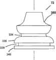
图17A-17D描述了根据本发明的一个实施例的的鼻垫的一个可替代实施例。在鼻垫72中,优选能够密封鼻孔的密封面380是可臌胀的或者可扩张的外壁382的外表面。图17A展示了具有弯曲密封面380的鼻垫72的正视图或者侧视图,密封面380的尺寸做成近似与用户的鼻孔口配合。在图17A中,鼻垫72未膨胀或者扩张。图17B显示了向外扩张、膨胀的鼻垫72。图17C展示了图17B在线A-A处的横截面。如图17C所示,鼻垫72包括带有密封面380的外壁382、内壁383、和位于外壁382和内壁383之间的袋子384。袋子384通过内壁383上的开口386与通气气体相通。因此当通气气体压力使得袋子384膨胀时,鼻垫的表面380优选扩张。图17D展示了图17C的F区域的详图。当吸入的通气气体流388在正压下流过鼻垫时,通过进出口386进入袋子384的通气气体388优选使密封的鼻垫密封表面380扩张。进出口386的开口可以倾斜成基本上与流过鼻垫的某些吸入的通气气体的方向共线,从而优选便于吸入的气体进入到袋子384内,便于袋子膨胀,并且便于外壁382扩张,从而优选实现在表面380和鼻孔边缘之间鼻孔边缘的接触面周围的保形密封。反之,在呼气过程中,通过鼻垫的呼出流(未显示)的方向基本上与进出口开口成180度,从此优选在进出口开口处产生文丘里效应,该效应优选抽出袋子内的一些空气,从而使外壁382和密封面380松驰,以便它不张紧在鼻孔组织上。当需要吸气时,通过让袋子中的气压略高于鼻垫外面鼻孔内的压力,该机构优选在吸气过程中提供有效密封,从而使通过密封的泄露最少。在呼气过程中,当不需要密封时,优选将较低的压力施加到鼻孔上。袋子384可以用任何合适的方法制造,例如通过弹性体二次模制工艺,其中在第一次模制时,鼻垫模制出内壁,然后在第二次模制时,在外面模制出外壁。如图17A-17C所示,鼻垫72还包括上述的其他特征,例如内弯334和垫座336,优选增加鼻垫的可压缩性和弯曲能力,以便更好地控制、调节或者限制鼻垫施加于鼻子和鼻孔上的力的大小。鼻垫还可以包括可与总管上的安装边缘和开口配合的凹槽338和根部保持凸缘340,根部保持凸缘340可以被插入通过总管的气流开口,从而更好地将鼻垫保持在适当的位置。17A-17D depict an alternative embodiment of a nose pad according to an embodiment of the present invention. In
图18A展示了根据本发明的一个实施例的可替代实施例,其中两个鼻垫被集成为一个鼻垫组件350。在这种实施例中,左和右鼻垫优选都被安装到优选包括上凸缘352、凹槽354和下凸缘356的根部上。凹槽优选与总管(未显示)上表面上的开口配合,并且上和下凸缘优选卡住总管上的开口周围的总管上壁。鼻垫组件350可以设置成各种尺寸、形状、间隔和角度。此外,该组件可以用可以由护理人员或者用户再成形或者再成型的材料制成,以便与用户的解剖结构配合。再成型可以通过许多合适的方式进行:例如通过用可以受热和再成形的热固性材料制造根部,或者通过将可延展元件包括在该组件的结构内,以便将它弯曲成想要的形状。在另一个实施例中,如图18B所示,鼻垫组件350’可以包括弯曲的根部,以便于鼻垫或者鼻垫组件能弯曲和吸收总管和鼻垫在使用过程中可能遇到的力,优选更好地保持舒服和密封完整性。弯曲的根部可以包括可压缩的根部垫座358和弯曲凹槽359。FIG. 18A illustrates an alternative embodiment of an embodiment of the present invention wherein two nose pads are integrated into one
图19展示了根据本发明的一个实施例的旋转弯管接头组件90的一个实施例。旋转弯管接头组件90可用于将总管单侧连接到通气气体供应软管上。旋转弯管接头组件90优选包括至少两个部件:优选安装在总管上的远端接头370,和弯管接头372,弯管接头372的远端优选安装在远端接头370上,而其近端优选安装到通气供应软管上。远端接头370和弯管接头372优选用可旋转的旋转接头371彼此连接。配合的直径表面优选包括(a)小距离的分隔,从而允许自由旋转,例如远端接头370的内径和弯管接头371的外径之间有大致0.005″的间隙,和(b)其中一个接头的直径上的凸脊378和另一个接头直径上的配合凹槽377,它们在这两个接头之间优选产生低气压密封。在两个接头之间可以选择一条小的气体流通路径,以允许在15cmH2O的压力下渗漏优选小于100ml/min。在图19中,远端接头370和弯管接头372之间的配合直径表面在该横截面侧视图中显示为直的,这优选便于在这两个部分之间可旋转地回转。然而,可替代地,两个配合表面也可以是弯曲的,例如局部球面,以允许弯头在多个平面中回转,例如在矢状面、横剖面、冠状面或者它们的任何结合中。弯管接头372的弯头部分显示具有角度d。角度d优选大于90度,这优选能减小通过该接头的弯头的气流阻力,但角度d优选小于180度,这优选将该供气连接件弯曲到所希望的方向,优选远离用户面部的中心,远离颊骨,和/或远离耳朵。角度d最优选在100-140度之间。远端接头370的远端优选包括直的直径表面,若干通孔374位于该表面中或者该表面上,用于连接总管连接环200或者200’(未显示)。远端接头370优选被连接到总管上,以便接头370上的孔374与总管上的孔(例如如图5所示的孔244或者如图6所示的孔278)对齐。接头和总管可以包括键槽特征(未显示),以便于孔的对齐。在连接时,连接环200或者200’上的倒钩可以压过总管和远端接头上这两组对齐的孔,从而将环、总管和远端接头紧固在一起。可替代地,远端接头可以包括沿径向向外突出的突出倒钩,倒钩会压过总管上的孔和连接环上的孔。连接的倒钩和孔式是示范性的,并且其他形式的连接也被归入本发明的某些实施例;例如可以使用快速连接、干涉配合连接或者舌槽连接。也可以选择通过在制造过程中将环、接头和总管部件中的两个或多个通过粘合或者接合预装配在一起,并以预装配或者半预装配的形式提供给用户。弯管接头372的近端优选可以适合于连接到供气软管,优选弯曲的软管,其可以弯曲以吸收力,并且可以定位在最舒服或者所希望的位置。旋转接头和弯管接头优选由热塑性塑料构成,例如聚丙烯,聚乙烯,聚砜,尼龙或者聚氯乙烯,并且壁厚优选为0.030-0.060″。Figure 19 illustrates an embodiment of a swivel elbow
图20更详细地展示了右互连组件的一个实施例。左互连组件的实施例可以优选是右组件的镜像。互连组件110也可以称为总管-头部带连接组件,包括连接环200和连接板202。连接环可以是局部环,优选在圆周上大于90度,或者可以是完整的360度环,并且优选包括沿径向向内突出的倒钩206,这些倒钩的间隔和尺寸优选可以做成对齐并且压过总管环连接孔(例如如图5所示的孔244或者如图6所示的孔278)和远端接头通孔374(例如如图19所示)。这些倒钩和孔仅仅是示范性的,其他形式的连接也被包括在本发明的某些实施例内。连接环200优选座在总管上的配合凹槽(例如图7中的总管连接环凹槽274)内,优选在连接环200和总管之间产生齐平的表面。连接环200的边缘可以选择被倒圆,以便连接到总管上时,装配表面优选大致平滑,并且优选没有尖锐的边缘。连接环200优选可以绕总管旋转,从而在它连接到总管上的位置处改变,以便获得鼻垫在矢状面中的更合适的角度,便于让鼻垫与鼻孔在矢状面中更好地对齐。头部带连接板202优选将连接环200连接到头部带组件80的前带上。连接板202优选倾斜或者弯曲,以便在使用时,它优选能够从其前缘到其后缘向侧部并向后延伸,这样其形状优选更好地配合面部侧部到鼻子的弯曲,并且它优选保持与皮肤更好地接触。连接板202的前侧优选可以是半刚性的,例如邵氏硬度为60-90A,例如优选以便赋予连接板足够的结构刚度,以致来自头部带组件的勒力被有效地传递到总管,以将总管稳定在鼻子下方的合适位置,且无过大的余隙或者松驰。连接板202的后侧或者皮肤侧优选包括连接板衬垫204,衬垫优选由柔软、易弯、有弹性和/或无磨损的材料制成,并且优选鼻垫连接板202贴着皮肤,吸收带的勒力,和/或提供更舒服的配合。连接板202和连接环200还可以选择包括力吸收部分,例如弹簧部分,力吸收部分优选可以便于吸收突然的力,并且如果总管偶然暴露于突然的或者过度的力下,可以避免总管移位。连接板202优选包括连接该连接板和头部带组件的接头;优选使用旋转接头,不过也可以使用其他类型的接头。在图20所示的实施例中,连接接头被描绘为突出的倒钩218,头部带组件上的配合孔(例如图21中的216)可以压在该倒钩上。连接板和头部带组件之间的其他形式的连接也包含在本发明的一些实施例中,例如摁扣或者舌槽。在最佳实施例中连接板202紧贴皮肤,前头部带放在板上;但在相反的布置方式中,前头部带紧贴皮肤,而连接板202放在前头部带上,该布置方式也包含在本发明的某些实施例中。在后一个例子中,举例来说,如果使用带倒钩的连接,那么倒钩优选从前头部带加强构件伸出,并且连接板202上的孔被摁在倒钩上。该板可以选择用可延展的或者易弯的材料制造,这样临床医生或者用户可以将该曲线塑造成对用户舒服的形状。可替代地,连接板可以包括位于柔软基底材料内的可延展的条,例如包裹在邵氏硬度为10-30A的弹性体材料内的邵氏硬度为90A的热塑性聚氯乙烯材料。由连接板202和头部带组件之间的连接形成的旋转接头优选允许两个组件之间旋转,优选旋转多达90度。举例来说,旋转接头可以根据来自主要解剖学结构的力自由地旋转;或者可以抵抗旋转,以使其必须被手动旋转到所要求的设置;或者可以包括离散的旋转设置,例如按1-15度递增,优选3-5度递增,以便用户能将该角度设置为最希望的角度。在后一个例子中,连接可以设置在用户最希望的旋转角处,并且一旦设置,优选会阻止旋转。举例来说,这些设置可以通过连接板前侧上的突出的通道和被压到连接板上的前带加强构件后侧上的配合槽口来提供。连接板的前后长度优选为0.5-1.5″,高度优选为0.25-0.75″,厚度包括板和可选择的连接板衬垫,优选为0.080-0.160″。优选通过在总管和前头部带之间设置两个独立的调节器-例如一个旋转连接和一个枢转连接,对每个个人用户来说,该连接组件优选有助于整个组件,包括总管和鼻垫,的可调整性和舒服的配合。Figure 20 illustrates one embodiment of the right interconnect assembly in more detail. Embodiments of the left interconnect assembly may preferably be a mirror image of the right assembly. The
图21和22更详细地展示了头部带组件的一个实施例。图21显示了头部带组件80的等距视图,而图22提供了侧视图。该组件包括左和右前头部带219’、219,其中左和右前头部带包括第一材料210’、210和被缝合或者连接到第一材料210’、210上的左和右前加强构件212’、212;和优选具有扣环214的后带221;以及可选择的具有扣环215的顶带223。头部带组件优选可以用连接板组件110、110’(例如图2、3、和20中的)连接到总管上。头部带组件优选沿上-后方向施加拉力于总管上,这让鼻垫(例如图1所示的鼻垫70)产生作用在鼻孔的密封力。任何不希望的过大的力可以优选被如下部件吸收:一个或多个连接板衬垫(例如图3和20中的204、204’),优选由弹性材料构成的总管,可选择的鼻垫弯曲和压缩特征,可选择的位于总管后侧上的护皮垫(例如图11中的230),或者它们的任何结合。在本发明的某些实施例中,头部带可以由织物或者弹性体材料或者它们的结合构成。如果是弹性体材料,举例来说,这些带可以是泡沫、氯丁橡胶、硅树脂、尿烷、橡胶、或者尿烷-聚氯乙烯混合物。带可以选择主要包括非弹性体材料,点缀有弹性体材料或者橡胶材料,以便赋予带拉伸和压缩性质,从而便于整个头部带组件被舒服地配合到各种解剖学结构和头部尺寸。在0.2-4.0磅的张力下,更优选在1.0-2.0的张力下,带的延伸率优选可以是50%,除在加强构件212、212’的区域之外,这优选阻止在这些力下伸长。加强构件的优选材料为邵氏硬度为60-90A的材料,例如可以是聚氯乙烯、聚乙烯、尼龙、聚丙烯、Ultem或者聚砜。带状弹性体材料优选可以厚0.040-0.120″,而加强构件优选可以厚0.010-0.050″。在本发明的某些实施例中,头部带可以用中等软度的材料制造,例如邵氏硬度为10-40A的材料,并且可以包括位于该材料内部并且由其包围或者连接到该材料上的较硬的加强构件;举例来说带可以包括由弹性体包围的0.020″厚的热塑性材料条。在本发明的某些实施例中,加强构件可以是很薄的轻金属条,举例来说,诸如铜、黄铜或者镍。在前左和右带的前端附近,头部带和/或头部带的加强构件优选包括配合的连接特征,以将头部带和/或头部带的加强构件连接到连接板202、202’上,优选将头部带组件固定到总管上。在图21和22所示的实施例中,配合的连接特征显示为通过包括加强构件的头部带的孔216,该孔连接在连接板倒钩218(例如图20所示的)上;然而,该配合连接特征仅仅是示范性的,其他连接特征也包含在本发明的某些实施例中。每个加强构件212、212’可以选择被分成两个或多个位于左右每一侧上的元件并被布置以使前带可以伸长,从而进一步便于更用户化地与个人用户匹配。顶和后头部带优选包括扣环或者Velcro连接,以便根据需要张紧带子,从而更好地与个人的解剖学结构配合。也可以用其他形式的连接来扣紧头部带,例如摁扣,按钮或者扣环。无论使用哪种连接机构,都优选是可调节的。例如,可以提供几套摁扣。头部带组件优选可以为用户提供多于一个尺寸,对成人来说,优选至少两种尺寸。前带长度优选为3-6″,后带长度优选为8-15″,可选择的顶带的长度优选为8-15″。Figures 21 and 22 illustrate one embodiment of the headgear assembly in more detail. Figure 21 shows an isometric view of the
图23A到23C展示了总管端盖的一个实施例,其优选用于单侧密封总管的一侧。端盖100优选配置成能被滑动插入总管的侧端。端盖100优选密封或者基本上密封使气流不进入端盖100所插入的总管的侧端。图23A展示了端盖100的侧视图,显示了连接环孔376和斜面390。图23C展示了通过图23B所示的端视图的横截面图,显示了连接环孔376和斜面390。斜面390优选通过减少或者消除可以由封闭端盖引起的在总管远端混合的气流湍动,便于层状气流进出总管和鼻垫。斜面390是可选择的,根据本发明某些实施例的端盖可以包括其他内部轮廓,而不是斜面,例如平的、凹的、凸的、复合弯曲或者弓形的表面。连接环孔376优选与总管上的连接环连接孔(例如图5所示的孔244或者图6所示的孔278)匹配,倒钩(例如连接环200或者200’上的倒钩206)优选被压过这些孔,从而将总管、端盖和头部带互连组件连接在一起。可替代地,端盖可以包括沿径向向外突出的突出倒钩,所述倒钩会压过总管上的孔和连接环上的孔。端盖可以由类似于远端接头的材料构成。Figures 23A to 23C illustrate one embodiment of a manifold end cap, which is preferably used for single-sided sealing of one side of the manifold. The
在一个可选择的实施例中,左和右连接板202’、202和总管后护皮垫230被合并成一个连续组件。在这些实施例中,该组合组件长于鼻子的宽度,头部带组件的前带被连接到该组件的左和右两侧。该组件可以固定到总管上,或者可以可拆卸地连接到总管上。In an alternative embodiment, the left and right connecting plates 202', 202 and manifold
图24A展示了本发明的一个可替代实施例,其中鼻子通气界面包括总管400,总管拥有位于总管上侧或者顶侧上的凹入的或者上部扫略曲线402以及位于总管下侧或者底侧上的凹入的或者下部扫略曲线404。曲线的半径以及总管的长度可以变化,从而为面部尺寸不同的病人提供不同的尺寸。例如,临床医生可以为病人佩戴尺寸和曲线合适的总管,或者可以为一个病人提供多个总管。上表面上的凹曲线优选允许总管更好地贴合鼻子下方和鼻子两侧的面部的几何形状,最不硌人。例如,未弯曲的总管可能需要鼻垫根部和鼻孔之间有更大的间距,这使得总管较大。总管底面上相对的凹曲线优选允许总管更好地贴合上唇以上的面部的解剖学结构。该曲线优选符合嘴唇的弯曲,从而形成优选不妨碍嘴唇的形状。例如,未弯曲的总管可能会在唇中央紧密接触或者接触上唇,因为总管的从上至下的宽度优选宽得足以接受通气供给源的接头。通过在总管的上和下表面上使用相对的凹曲线使总管中部的从上至下的宽度变窄,以及使其侧端变宽,对某些病人来说,这种设计可能有利于避免接触嘴唇,优选大得足以连接到通气供给源上,并且优选与鼻子匹配得最佳,从而对某些病人来说,产生优选的可能配合和最小的硌人可能。可能会认为总管中心附近的横截面尺寸的限制可能会不必要地增加流阻;然而这一设计有利的是,因为50%的流动进入近端鼻垫而不需要跨越该限制截面,而只有50%需要跨越该限制截面,所以优选地本设计的总流阻没有很大增加。还表明,上表面上的凹曲线优选使鼻垫定位为向内倾斜,这优选更好地符合鼻孔角度的解剖学结构。Figure 24A shows an alternative embodiment of the present invention in which the nasal ventilation interface includes a manifold 400 having a concave or upper
除了如上所述的相对的凹曲线的特征和功能之外,图24A还展示了总管后侧上的可选择的护皮垫的其他细节。在该实施例中,护皮垫230可用于倾斜设置总管在矢状面中的角度,以便鼻垫406可以与鼻孔在矢状面中的倾角更一致。此外,护皮垫230优选可以设计成能吸收由头部带组件紧固带施加的将总管向后拉到贴住用户的皮肤上的力。护皮垫可以和总管一体成形,或者可以是连接到总管上的单独的部件。在后一个例子中,护皮垫可以可拆卸地连接到总管上,因此可以连接各种尺寸,以便为用户提供定制和个性化配合,并在必要时更换和清洁衬垫。护皮垫优选覆盖总管的宽度截面,这优选有助于稳定总管的角度,并且有助于吸收或者分散带子的勒力。护皮垫可以选择伸过总管的侧端,并且可以选择用于连接总管组件和头部带组件,在这种情况下,护皮垫的侧端将包括具有连接特征的硬质插入物,以连接头部带组件的前带。该连接特征例如为如上所述的倒钩或者孔。护皮垫优选可以由粘弹性的或者非常柔顺的材料构成。图24B展示了图24A的总管在线A-A处的横截面,并展示了连接到总管后侧的护皮垫。In addition to the features and functions of the opposing concave curves described above, Figure 24A shows additional details of the optional leather pad on the rear side of the manifold. In this embodiment, the
另如图24A的实施例所示,可选择的排气孔可以设置在供气组件旋转弯管接头90的接头410上,以便允许呼出气流412。作为另一个可替代方案,可选择的排气孔可以设置在供气组件旋转弯管接头90上,以便允许呼出气流。排气孔可以优选偏斜,以便其在呼气方向上流阻较小,而在吸气方向上流阻较大。该组件内的通道的开口优选位于仅在呼气方向上被气流冲击的表面上。作为另一个可替代方案,当气体沿呼气方向移动时,接头410的一部分可以随气流的惯性在旋转弯管接头组件90内移动,从而移动接触排气通道,因此排气孔在吸气过程关闭得较多,而在呼气过程中关闭得较少,接头的移动部分的表面或者相对的表面优选可以由柔软材料构成,以防止与活动部件有关的噪音。图24A的实施例还显示了连接到总管上的鼻垫406,其中总管使鼻垫向内倾斜,其中内边缘是直的,而外边缘向内倾斜,以便向内和向的外缘与鼻孔的典型的解剖学结构配合,其中鼻孔隔膜基本上是直的,而鼻孔外壁基本上是向内倾斜的。鼻垫上的可选择的密封台阶408也可以是斜的,以便更好地与通常斜着的鼻孔口配合。鼻垫优选可以从近端的根部到末梢渐缩。图24A的实施例所示的特征可以单独或者任意结合使用,并且可以与本发明的其他实施例中描述的特征,例如总管的后曲线或者可拆卸的鼻垫,结合使用。As also shown in the embodiment of FIG. 24A , optional vent holes may be provided on the fitting 410 of the swivel elbow fitting 90 of the air supply assembly to allow exhaled
图25展示了本发明的一个实施例,其中总管420具有扫略的、弯曲的和渐缩的形状。总管420的后侧或者病人的皮肤侧P优选包括对称的凹曲线422,优选贴合鼻子下方的面部轮廓。总管前侧优选包括不对称的曲线424,以使总管的宽度从右到左渐缩。总管的因渐缩引起的尺寸减小的端部位于用户侧眠时所压的脸的那一侧,从而优选减小该区域中界面的笨大,优选使它在该侧侧眠时更舒服。供气组件可以连接到总管的与渐缩侧相对的一侧。总管的两端具有头部带接头配合特征426,例如凹槽,以将总管安装固定到头部带组件上,头部带组件将总管固定紧固到面部。该实施例优选有两个方案供用户选择:一个尖端在左,一个尖端在右,因此用户可选择侧眠在哪一侧上。在一个成套组件中可以为用户提供两个方案,以便用户可以在两个方案之间根据需要切换。Figure 25 illustrates an embodiment of the present invention wherein the manifold 420 has sweeping, curved and tapered shapes. The posterior or patient's skin side P of the manifold 420 preferably includes a symmetrical
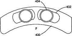
图26展示了总管的一个实施例,其中鼻垫之间的间距可以调节。总管430包括自密封调节狭槽432,鼻密封垫434可以在其中滑动。Figure 26 shows an embodiment of a manifold where the spacing between the nose pads can be adjusted. The manifold 430 includes a self-sealing
在另一个可选择的实施例中,总管或者鼻垫可以包括可以容纳芳香治疗物质的孔隙。这些孔隙被配置成用于缓慢释放所述物质,以便所述物质在1-8小时内从这些孔隙中耗尽。该界面组件可以选择包括容纳芳香治疗盒的贮器部分。另外,鼻子界面组件包括用于连接富氧气体补充源的连接和用于主动从该组件的管道中除去富含CO2气体的连接。In another alternative embodiment, the manifold or nasal pads may include apertures that may receive an aromatherapy substance. The pores are configured for slow release of the substance so that the substance is depleted from the pores within 1-8 hours. The interface assembly may optionally include a reservoir portion for receiving an aromatherapy cartridge. In addition, the nose interface assembly includes connections for connecting a supplemental source of oxygen-enriched gas and connections for actively removing CO2- enriched gas from the assembly's plumbing.
在一个可选择的实施例中,刚性圆柱形薄壁套筒被放置在总管端部内,从而形成硬质的总管侧端。然后,端盖或者旋转弯管接头被压到圆柱形套筒内。In an alternative embodiment, a rigid cylindrical thin walled sleeve is placed within the manifold end to form a rigid manifold side end. The end cap or swivel elbow is then pressed into the cylindrical sleeve.
不难理解鼻子界面装置可以包含任何、某些或者所有的上述实施例,并且上述实施例可以用未明确说明的方式结合。此外,尽管所述的大部分实施例都涉及该装置的长期或者重复使用,例如阻塞性睡眠呼吸暂停,但是不难理解还有非阻塞性睡眠呼吸暂停通气应用也会受益于这些实施例,例如用于慢性阻塞性肺病(COPD)的气道正压力治疗、麻醉供给和恢复、戒除机械呼吸器、无创通气、门诊外科应用以及紧急通风。此外,不难理解除了连续气道正压力或者大小连续变化的气道正压力通气之外,本发明的各实施例也可用于其他形式的机械通风,例如容量控制通气(CMV)、同步间歇指令通气(SIMV)等等。对于某些实施例,在装置的某些应用中,让气源与总管的左和右两个侧端相连是有益的。最后还应该理解通过必要的改变,该装置可以是可重复使用的或者一次性的,并且可以适合于成人、儿童或者初生儿使用。虽然已经参考本发明的最佳实施例对本发明进行了详细描述,但对本领域熟练技术人员来说显而易见的是,只要不脱离本发明,就可以进行各种变化和改变,并且可以采用等价的实施例。It will be appreciated that the nose interface device may comprise any, some, or all of the above-described embodiments, and that the above-described embodiments may be combined in ways not expressly described. Furthermore, while most of the embodiments described relate to long-term or repeated use of the device, such as obstructive sleep apnea, it is understood that there are also non-obstructive sleep apnea ventilation applications that would benefit from these embodiments, such as Positive airway pressure therapy, anesthesia delivery and recovery, mechanical ventilator weaning, noninvasive ventilation, outpatient surgical applications, and emergency ventilation for chronic obstructive pulmonary disease (COPD). In addition, it is not difficult to understand that in addition to continuous positive airway pressure or continuously variable positive airway pressure ventilation, the various embodiments of the present invention can also be used in other forms of mechanical ventilation, such as volume-controlled ventilation (CMV), synchronized intermittent instruction Ventilation (SIMV) and more. For some embodiments, in certain applications of the device, it may be beneficial to have the air supply connected to both the left and right side ends of the manifold. Finally it should also be understood that the device may be reusable or disposable, mutatis mutandis, and may be adapted for adult, child or neonatal use. Although the invention has been described in detail with reference to the preferred embodiment thereof, it will be apparent to those skilled in the art that various changes and changes can be made and equivalents can be employed without departing from the invention. Example.
尽管对于这里描述的所有实施例都没有明确地展示或者描述呼吸器,但是本发明的各实施例优选和呼吸器一起使用,呼吸器的非限定性的例子包括连续气道正压力、大小连续变化的气道正压力和自动滴定气道正压力呼吸器,以及机械呼吸器、喷射呼吸器和其他非常规的呼吸器。Although a respirator is not explicitly shown or described for all of the embodiments described herein, embodiments of the invention are preferably used with respirators, non-limiting examples of which include continuous positive airway pressure, continuously variable in size positive airway pressure and auto-titrating positive airway pressure respirators, as well as mechanical respirators, jet respirators and other unconventional respirators.
尽管上述说明专注于本发明的最佳实施例,但需要指出的是,其他变化和改变对本领域熟练技术人员来说是显而易见的,并且只要不脱离本发明的范围的精神,就可以进行其他变化和改变。此外,与本发明的一个实施例一起描述的特征可以和其他实施例一起使用,即使在上文中没有明确陈述。Although the above description has focused on the preferred embodiment of the present invention, it should be noted that other variations and modifications will be apparent to those skilled in the art, and other changes can be made without departing from the scope and spirit of the present invention. and change. Furthermore, features described in connection with one embodiment of the invention may be used with other embodiments even if not explicitly stated above.
只要不脱离本发明的精神,本发明就可以用其他特殊的形式来体现。对于已经掌握这里揭示的内容的本领域熟练技术人员来说,这类其他的实施例和形式是清楚的。无论从哪一点来看,公开的各实施例都仅仅是作为说明性的而非限制性的内容来考虑的。The present invention can be embodied in other specific forms as long as it does not depart from the spirit of the present invention. Such other embodiments and forms will be apparent to those skilled in the art having the knowledge disclosed herein. In any case, the disclosed embodiments are to be considered as illustrative rather than restrictive.
Claims (30)
Applications Claiming Priority (5)
| Application Number | Priority Date | Filing Date | Title |
|---|---|---|---|
| US654808P | 2008-01-18 | 2008-01-18 | |
| US61/006,548 | 2008-01-18 | ||
| US10641408P | 2008-10-17 | 2008-10-17 | |
| US61/106,414 | 2008-10-17 | ||
| PCT/US2009/031355WO2009092057A1 (en) | 2008-01-18 | 2009-01-16 | Methods and devices for improving efficacy of non-invasive ventilation |
Publications (1)
| Publication Number | Publication Date |
|---|---|
| CN101977656Atrue CN101977656A (en) | 2011-02-16 |
Family
ID=40875454
Family Applications (1)
| Application Number | Title | Priority Date | Filing Date |
|---|---|---|---|
| CN2009801095400APendingCN101977656A (en) | 2008-01-18 | 2009-01-16 | Method and device for improving the efficiency of non-invasive ventilation |
Country Status (7)
| Country | Link |
|---|---|
| US (1) | US20090183739A1 (en) |
| EP (1) | EP2240245A1 (en) |
| JP (1) | JP2011509762A (en) |
| CN (1) | CN101977656A (en) |
| AU (1) | AU2009205945A1 (en) |
| CA (1) | CA2712481A1 (en) |
| WO (1) | WO2009092057A1 (en) |
Cited By (11)
| Publication number | Priority date | Publication date | Assignee | Title |
|---|---|---|---|---|
| CN103619391A (en)* | 2011-06-21 | 2014-03-05 | 雷斯梅德有限公司 | Pap system |
| CN104127966A (en)* | 2014-08-08 | 2014-11-05 | 詹育边 | Nasal mask device and nasal mask combined filter |
| CN105979995A (en)* | 2013-10-16 | 2016-09-28 | 费雪派克医疗保健有限公司 | patient interface |
| CN106999693A (en)* | 2014-09-19 | 2017-08-01 | 费雪派克医疗保健有限公司 | Patient interface |
| CN106999686A (en)* | 2014-12-08 | 2017-08-01 | 人类设计医疗有限公司 | Hybrid CPAP interface system for use with ventilation and positive air pressure systems |
| USD848614S1 (en) | 2017-11-21 | 2019-05-14 | Fisher & Paykel Healthcare Limited | Pad for nasal cannula assembly |
| USD849243S1 (en) | 2017-11-21 | 2019-05-21 | Fisher & Paykel Healthcare Limited | Nasal cannula |
| USD849242S1 (en) | 2017-11-21 | 2019-05-21 | Fisher & Paykel Healthcare Limited | Nasal cannula assembly |
| USD878549S1 (en) | 2017-11-21 | 2020-03-17 | Fisher & Paykel Healthcare Limited | Connector for nasal cannula assembly |
| CN112638458A (en)* | 2018-08-23 | 2021-04-09 | 皇家飞利浦有限公司 | Nasal portion and patient interface device including the same |
| CN113274609A (en)* | 2015-03-16 | 2021-08-20 | 费雪派克医疗保健有限公司 | Patient interface |
Families Citing this family (115)
| Publication number | Priority date | Publication date | Assignee | Title |
|---|---|---|---|---|
| WO2004052438A1 (en) | 2002-12-06 | 2004-06-24 | Fisher & Paykel Healthcare Limited | Mouthpiece |
| US7588033B2 (en) | 2003-06-18 | 2009-09-15 | Breathe Technologies, Inc. | Methods, systems and devices for improving ventilation in a lung area |
| CN1905917B (en) | 2003-08-18 | 2011-08-03 | 门罗生命公司 | Method and device for non-invasive ventilation with nasal interface |
| WO2005079726A1 (en) | 2004-02-23 | 2005-09-01 | Fisher & Paykel Healthcare Limited | Breathing assistance apparatus |
| EP3936180B1 (en) | 2004-04-02 | 2023-11-29 | Fisher & Paykel Healthcare Limited | Breathing assistance apparatus |
| US9072852B2 (en) | 2004-04-02 | 2015-07-07 | Fisher & Paykel Healthcare Limited | Breathing assistance apparatus |
| JP2009508645A (en) | 2005-09-20 | 2009-03-05 | ルッツ フレイテッグ, | System, method and apparatus for assisting patient breathing |
| USD623288S1 (en) | 2006-04-28 | 2010-09-07 | Resmed Limited | Patient interface |
| JP5191005B2 (en) | 2006-05-18 | 2013-04-24 | ブリーズ テクノロジーズ, インコーポレイテッド | Method and device for tracheostomy |
| DE202007019687U1 (en) | 2006-07-14 | 2015-07-14 | Fisher & Paykel Healthcare Ltd. | Respiratory support device |
| EP2068992B1 (en) | 2006-08-03 | 2016-10-05 | Breathe Technologies, Inc. | Devices for minimally invasive respiratory support |
| WO2008144589A1 (en) | 2007-05-18 | 2008-11-27 | Breathe Technologies, Inc. | Methods and devices for sensing respiration and providing ventilation therapy |
| EP2200686A4 (en) | 2007-09-26 | 2017-11-01 | Breathe Technologies, Inc. | Methods and devices for providing inspiratory and expiratory flow relief during ventilation therapy |
| EP2203206A4 (en) | 2007-09-26 | 2017-12-06 | Breathe Technologies, Inc. | Methods and devices for treating sleep apnea |
| US8573201B2 (en) | 2007-10-22 | 2013-11-05 | Resmed Limited | Patient interface systems |
| USD656231S1 (en) | 2009-04-20 | 2012-03-20 | Resmed Limited | Respiratory mask |
| WO2011014931A1 (en) | 2009-08-07 | 2011-02-10 | Resmed Ltd | Patient interface systems |
| US8776793B2 (en) | 2008-04-18 | 2014-07-15 | Breathe Technologies, Inc. | Methods and devices for sensing respiration and controlling ventilator functions |
| WO2009129506A1 (en) | 2008-04-18 | 2009-10-22 | Breathe Technologies, Inc. | Methods and devices for sensing respiration and controlling ventilator functions |
| USD652505S1 (en) | 2008-05-02 | 2012-01-17 | Resmed Limited | Left and right side strap and yoke for a mask |
| US10792451B2 (en) | 2008-05-12 | 2020-10-06 | Fisher & Paykel Healthcare Limited | Patient interface and aspects thereof |
| US10258757B2 (en) | 2008-05-12 | 2019-04-16 | Fisher & Paykel Healthcare Limited | Patient interface and aspects thereof |
| NZ618492A (en)* | 2008-06-05 | 2015-09-25 | Resmed Ltd | Treatment of respiratory conditions |
| US9072855B2 (en) | 2008-06-12 | 2015-07-07 | Fisher & Paykel Healthcare Limited | Breathing assistance apparatus |
| US11660413B2 (en) | 2008-07-18 | 2023-05-30 | Fisher & Paykel Healthcare Limited | Breathing assistance apparatus |
| CN102196837B (en) | 2008-08-22 | 2015-09-09 | 呼吸科技公司 | Methods and devices for providing mechanical ventilation utilizing an open airway interface |
| US8302602B2 (en) | 2008-09-30 | 2012-11-06 | Nellcor Puritan Bennett Llc | Breathing assistance system with multiple pressure sensors |
| US10252020B2 (en) | 2008-10-01 | 2019-04-09 | Breathe Technologies, Inc. | Ventilator with biofeedback monitoring and control for improving patient activity and health |
| EP2349428B1 (en)* | 2008-10-10 | 2017-09-20 | Fisher & Paykel Healthcare Limited | Nasal pillows for a patient interface |
| US8430098B1 (en)* | 2008-12-17 | 2013-04-30 | Venkata Buddharaju | Strapless nasal interface device |
| US20180064900A1 (en) | 2008-12-17 | 2018-03-08 | Venkata Buddharaju | Strapless nasal interface device |
| US9132250B2 (en) | 2009-09-03 | 2015-09-15 | Breathe Technologies, Inc. | Methods, systems and devices for non-invasive ventilation including a non-sealing ventilation interface with an entrainment port and/or pressure feature |
| CN111420208B (en) | 2009-04-02 | 2023-07-04 | 呼吸科技公司 | Methods, systems and devices for non-invasive open ventilation using a gas delivery nozzle within an outer tube |
| US9962512B2 (en) | 2009-04-02 | 2018-05-08 | Breathe Technologies, Inc. | Methods, systems and devices for non-invasive ventilation including a non-sealing ventilation interface with a free space nozzle feature |
| USD653748S1 (en)* | 2009-04-21 | 2012-02-07 | Resmed Limited | Headgear for a respiratory mask |
| US20100326441A1 (en)* | 2009-06-24 | 2010-12-30 | Shlomo Zucker | Nasal interface device |
| WO2011029074A1 (en) | 2009-09-03 | 2011-03-10 | Breathe Technologies, Inc. | Methods, systems and devices for non-invasive ventilation including a non-sealing ventilation interface with an entrainment port and/or pressure feature |
| EP2501423A4 (en) | 2009-11-18 | 2014-10-29 | Fisher & Paykel Healthcare Ltd | Nasal interface |
| CA3117178C (en)* | 2009-12-23 | 2023-06-13 | Fisher & Paykel Healthcare Limited | An interface and a method of supplying breathing gas |
| GB2489379B (en) | 2009-12-23 | 2016-01-13 | Fisher & Paykel Healthcare Ltd | Patient interface and headgear |
| BR112012017097A2 (en)* | 2010-01-15 | 2016-04-05 | Koninkl Philips Electronics Nv | kit for fitting a patient interface device to a patient's nostril, kit for closing a patient's gas flow and method of providing a customizable patient interface device |
| AU2010342299B2 (en)* | 2010-01-15 | 2014-07-17 | Koninklijke Philips Electronics N.V. | Replaceable nasal pillow |
| JP5563338B2 (en)* | 2010-03-16 | 2014-07-30 | アトムメディカル株式会社 | Nasal prong device |
| US9295801B2 (en) | 2010-05-25 | 2016-03-29 | Fisher & Paykel Healthcare Limited | Breathing tube |
| CA2807416C (en) | 2010-08-16 | 2019-02-19 | Breathe Technologies, Inc. | Methods, systems and devices using lox to provide ventilatory support |
| US9925349B2 (en)* | 2010-08-30 | 2018-03-27 | Koninklijke Philips N.V. | Patient interface device with a frame assembly having a double-Y supporting structure |
| CA2811423C (en) | 2010-09-30 | 2019-03-12 | Breathe Technologies, Inc. | Methods, systems and devices for humidifying a respiratory tract |
| EP2624903B1 (en) | 2010-10-08 | 2018-05-16 | Fisher & Paykel Healthcare Limited | Breathing assistance apparatus |
| TWI446940B (en)* | 2010-10-13 | 2014-08-01 | Hsiner Co Ltd | Nasal breathing apparatus |
| US10603456B2 (en) | 2011-04-15 | 2020-03-31 | Fisher & Paykel Healthcare Limited | Interface comprising a nasal sealing portion |
| GB2529079B (en) | 2011-04-15 | 2016-06-22 | Fisher & Paykel Healthcare Ltd | An elbow assembly for a mask |
| USD685463S1 (en)* | 2011-05-05 | 2013-07-02 | ResMed Limitd | Respiratory mask |
| US9138169B2 (en)* | 2011-09-07 | 2015-09-22 | Monitor Mask Inc. | Oxygen facemask with capnography monitoring ports |
| JP5872350B2 (en)* | 2012-03-28 | 2016-03-01 | 日本メディカルネクスト株式会社 | Nostril cannula |
| US8844526B2 (en) | 2012-03-30 | 2014-09-30 | Covidien Lp | Methods and systems for triggering with unknown base flow |
| EP2863979B1 (en) | 2012-06-20 | 2020-12-02 | Koninklijke Philips N.V. | Reversible frame for a patient interface assembly |
| GB2553475B8 (en) | 2012-08-08 | 2019-01-02 | Fisher & Paykel Healthcare Ltd | Headgear for patient interface |
| EP4279106A3 (en) | 2012-09-04 | 2024-01-17 | Fisher & Paykel Healthcare Limited | Valsalva mask |
| CA2925546C (en) | 2012-10-29 | 2022-06-14 | The University Of North Carolina At Chapel Hill | Methods and compositions for treating mucosal tissue disorders |
| WO2014091362A1 (en)* | 2012-12-11 | 2014-06-19 | Koninklijke Philips N.V. | Nasal cannula system and method |
| US20150314095A1 (en)* | 2012-12-13 | 2015-11-05 | Koninklijke Philips N.V. | Patient interface cushion with integral straps |
| WO2014108779A1 (en)* | 2013-01-10 | 2014-07-17 | Koninklijke Philips N.V. | Auto-adjusting headgear for a patient interface device |
| US9492629B2 (en) | 2013-02-14 | 2016-11-15 | Covidien Lp | Methods and systems for ventilation with unknown exhalation flow and exhalation pressure |
| JP6502862B2 (en) | 2013-03-07 | 2019-04-17 | コーニンクレッカ フィリップス エヌ ヴェKoninklijke Philips N.V. | Manifold assembly for breathing interface device |
| USD749205S1 (en)* | 2013-03-08 | 2016-02-09 | Fresca Medical, Inc. | Sleep apnea device |
| US9981096B2 (en) | 2013-03-13 | 2018-05-29 | Covidien Lp | Methods and systems for triggering with unknown inspiratory flow |
| CN116899065A (en)* | 2013-03-15 | 2023-10-20 | 费雪派克医疗保健有限公司 | Nasal cannula assemblies and related components |
| CN107961427B (en)* | 2013-07-17 | 2020-10-16 | 费雪派克医疗保健有限公司 | Patient interface and aspects thereof |
| US20150020811A1 (en)* | 2013-07-17 | 2015-01-22 | Upods, Llc | Oxygen delivery device |
| US9440039B2 (en)* | 2013-07-17 | 2016-09-13 | Upods, Llc | Gas delivery device |
| US9925348B2 (en) | 2013-07-17 | 2018-03-27 | Upods, Llc | Gas delivery device |
| ES2817076T3 (en) | 2013-08-09 | 2021-04-06 | Fisher & Paykel Healthcare Ltd | Asymmetric Nasal Delivery Elements and Accessories for Nasal Interfaces |
| US10709861B2 (en)* | 2013-09-20 | 2020-07-14 | Fisher & Paykel Healthcare Limited | Nasal cannula with flow restrictor |
| WO2015041547A1 (en)* | 2013-09-23 | 2015-03-26 | Fisher & Paykel Healthcare Limited | Nasal cannula with turbulation elements |
| USD771239S1 (en) | 2014-05-08 | 2016-11-08 | Fisher & Paykel Healthcare Limited | Crown strap of a headgear assembly for a breathing interface |
| CN110711304B (en) | 2014-06-18 | 2024-03-15 | 费雪派克医疗保健有限公司 | Patient interface and components |
| SG11201700351VA (en) | 2014-07-18 | 2017-02-27 | Fisher & Paykel Healthcare Ltd | Headgear clip arrangement |
| JP6317647B2 (en)* | 2014-08-19 | 2018-04-25 | アトムメディカル株式会社 | Nostril cannula |
| WO2016032343A1 (en) | 2014-08-25 | 2016-03-03 | Fisher & Paykel Healthcare Limited | Respiratory mask and related portions, components or sub-assemblies |
| SG10201902309XA (en)* | 2014-09-16 | 2019-04-29 | Fisher & Paykel Healthcare Ltd | Headgear for a respiratory mask |
| US10828452B2 (en) | 2014-09-16 | 2020-11-10 | Fisher & Paykel Healthcare Limited | Intramold headgear |
| JP6931326B2 (en) | 2014-09-16 | 2021-09-01 | フィッシャー アンド ペイケル ヘルスケア リミテッド | Headgear assembly and interface assembly with headgear |
| US10646680B2 (en) | 2014-09-19 | 2020-05-12 | Fisher & Paykel Healthcare Limited | Headgear assemblies and interface assemblies with headgear |
| US9925346B2 (en) | 2015-01-20 | 2018-03-27 | Covidien Lp | Systems and methods for ventilation with unknown exhalation flow |
| CA2977729A1 (en) | 2015-03-04 | 2016-09-09 | Fisher & Paykel Healthcare Limited | Mask system headgear |
| EP3259003B1 (en)* | 2015-03-27 | 2020-09-30 | Fisher & Paykel Healthcare Limited | Patient interface and aspects thereof |
| CN107530519B (en)* | 2015-03-30 | 2021-09-03 | 费雪派克医疗保健有限公司 | Patient interface |
| KR102662489B1 (en) | 2015-03-31 | 2024-05-02 | 피셔 앤 페이켈 핼스케어 리미티드 | User interface and system for gassing the airway |
| CA2980528A1 (en)* | 2015-03-31 | 2016-10-06 | Fisher & Paykel Healthcare Limited | Nasal cannula |
| EP3430284B1 (en) | 2016-03-16 | 2021-07-14 | Fisher & Paykel Healthcare Limited | Directional lock for interface headgear arrangement |
| SG11201807699TA (en) | 2016-03-16 | 2018-10-30 | Fisher & Paykel Healthcare Ltd | Strap assembly, strap connector, headgear, headgear assembly, method of forming headgear, tubular connector, patient interface and method of joining straps |
| AU2017234345B2 (en) | 2016-03-16 | 2022-03-03 | Fisher & Paykel Healthcare Limited | Intra-mould substrate |
| USD882066S1 (en) | 2016-05-13 | 2020-04-21 | Fisher & Paykel Healthcare Limited | Frame for a breathing mask |
| EP3995168B8 (en)* | 2016-08-11 | 2025-09-03 | Fisher & Paykel Healthcare Limited | A collapsible conduit, patient interface and headgear connector |
| USD870269S1 (en) | 2016-09-14 | 2019-12-17 | Fisher & Paykel Healthcare Limited | Nasal cannula assembly |
| GB2570094B (en)* | 2016-10-18 | 2022-06-01 | Fisher & Paykel Healthcare Ltd | Valve module and filter |
| US10913512B2 (en) | 2016-12-07 | 2021-02-09 | Arctic Cat Inc. | Drive train components for recreational vehicles |
| USD824020S1 (en) | 2017-02-23 | 2018-07-24 | Fisher & Paykel Healthcare Limited | Cushion assembly for breathing mask assembly |
| USD823455S1 (en) | 2017-02-23 | 2018-07-17 | Fisher & Paykel Healthcare Limited | Cushion assembly for breathing mask assembly |
| USD823454S1 (en) | 2017-02-23 | 2018-07-17 | Fisher & Paykel Healthcare Limited | Cushion assembly for breathing mask assembly |
| US11524132B2 (en) | 2017-05-22 | 2022-12-13 | Vayu Global Health Innovations, LLC | Adjustable ambient air-oxygen blender |
| US12102764B2 (en) | 2017-06-26 | 2024-10-01 | Fisher & Paykel Healthcare Limited | Respiratory mask system |
| US10792449B2 (en) | 2017-10-03 | 2020-10-06 | Breathe Technologies, Inc. | Patient interface with integrated jet pump |
| WO2019123348A1 (en) | 2017-12-21 | 2019-06-27 | Fisher & Paykel Healthcare Limited | Respiratory mask system |
| EP3765135B1 (en) | 2018-03-16 | 2024-11-27 | Fisher & Paykel Healthcare Limited | Headgear with lock disengagement mechanism |
| USD885556S1 (en)* | 2018-04-13 | 2020-05-26 | Fisher & Paykel Healthcare Limited | Tip, tube and clip assembly for a gas sampling apparatus |
| JP6980277B2 (en)* | 2018-06-18 | 2021-12-15 | 学校法人産業医科大学 | Nasal cannula |
| USD894372S1 (en)* | 2018-07-27 | 2020-08-25 | Cooltech, Llc | Mask |
| USD986410S1 (en)* | 2018-07-27 | 2023-05-16 | Cooltech, Llc | Mask |
| EP3990079B1 (en)* | 2019-06-28 | 2024-08-07 | ResMed Pty Ltd | Conduit headgear |
| US11846390B2 (en) | 2020-06-04 | 2023-12-19 | Meta Platforms Technologies, Llc | Pass-through ratcheting mechanism |
| US11982400B2 (en)* | 2020-08-04 | 2024-05-14 | Meta Platforms Technologies, Llc | Head cradle for head-mounted display and related systems and devices |
| US20240091482A1 (en)* | 2022-09-21 | 2024-03-21 | Oxfo Corporation | Nasal Cannula |
| CN120659635A (en)* | 2023-02-07 | 2025-09-16 | 轻松氧气有限责任公司 | Nasal catheter |
| WO2024207063A1 (en)* | 2023-04-04 | 2024-10-10 | ResMed Pty Ltd | Headgear for patient interfaces |
Family Cites Families (98)
| Publication number | Priority date | Publication date | Assignee | Title |
|---|---|---|---|---|
| US2735432A (en)* | 1956-02-21 | hudson | ||
| US718785A (en)* | 1902-09-16 | 1903-01-20 | James Welch Mcnary | Respirator. |
| US909002A (en)* | 1908-06-03 | 1909-01-05 | Napoleon Lambert | Respirator. |
| US1125542A (en)* | 1914-03-11 | 1915-01-19 | Aubrey Humphries | Apparatus for use in administering anesthetics. |
| US1129619A (en)* | 1914-07-10 | 1915-02-23 | Gustave A Zapf | Inhaling system. |
| US1331297A (en)* | 1918-11-13 | 1920-02-17 | Luther J Walker | Ventilating apparatus |
| US3493703A (en)* | 1968-08-02 | 1970-02-03 | James E Finan | Body motion sensitive electrical switch with lost motion means |
| US3643660A (en)* | 1969-11-21 | 1972-02-22 | Allan C Hudson | Nasal cannula |
| US3794026A (en)* | 1970-07-29 | 1974-02-26 | H Jacobs | Ventilating apparatus embodying selective volume or pressure operation and catheter means for use therewith |
| US3794072A (en)* | 1972-06-26 | 1974-02-26 | Hudson Oxygen Therapy Sales Co | Oxygen diluter device |
| GB1558060A (en)* | 1975-07-29 | 1979-12-19 | Medishield Corp Ltd | Lung ventilator |
| US4003377A (en)* | 1975-08-21 | 1977-01-18 | Sandoz, Inc. | Patient ventilator |
| US4367735A (en)* | 1979-12-31 | 1983-01-11 | Novametrix Medical Systems, Inc. | Nasal cannula |
| US4495946A (en)* | 1981-03-17 | 1985-01-29 | Joseph Lemer | Artificial breathing device |
| US4803981A (en)* | 1981-09-22 | 1989-02-14 | Vickery Ian M | Anaesthesia mask |
| GB2118442A (en)* | 1982-04-15 | 1983-11-02 | James Gordon Whitwam | Improvements in or relating to respirators |
| US4506666A (en)* | 1982-12-03 | 1985-03-26 | Kircaldie, Randall And Mcnab | Method and apparatus for rectifying obstructive apnea |
| FR2556974B1 (en)* | 1983-12-27 | 1988-02-19 | Commissariat Energie Atomique | ERGONOMIC HEAT |
| US5090408A (en)* | 1985-10-18 | 1992-02-25 | Bryan T. Spofford | Transtracheal catheter system and method |
| US5181509A (en)* | 1984-11-21 | 1993-01-26 | Spofford Bryan T | Transtracheal catheter system |
| FI81500C (en)* | 1985-05-23 | 1990-11-12 | Etelae Haemeen Keuhkovammayhdi | Respiratory Treatment Unit |
| US4808160A (en)* | 1986-04-14 | 1989-02-28 | Timmons John W | Nasal cannula apparatus |
| US4807616A (en)* | 1987-07-09 | 1989-02-28 | Carmeli Adahan | Portable ventilator apparatus |
| US4782832A (en)* | 1987-07-30 | 1988-11-08 | Puritan-Bennett Corporation | Nasal puff with adjustable sealing means |
| US4807617A (en)* | 1988-02-01 | 1989-02-28 | Massachusetts Eye And Ear Infirmary | Scavenging mask |
| JPH01223966A (en)* | 1988-03-01 | 1989-09-07 | Sumitomo Bakelite Co Ltd | Respirator |
| US4899740A (en)* | 1989-01-17 | 1990-02-13 | E. D. Bullard Company | Respirator system for use with a hood or face mask |
| US4989599A (en)* | 1989-01-26 | 1991-02-05 | Puritan-Bennett Corporation | Dual lumen cannula |
| US5184610A (en)* | 1989-03-06 | 1993-02-09 | Hood Laboratories | Tracheal cannulas and stents |
| US5101820A (en)* | 1989-11-02 | 1992-04-07 | Christopher Kent L | Apparatus for high continuous flow augmentation of ventilation and method therefor |
| US4990157A (en)* | 1989-11-13 | 1991-02-05 | Robhill Industries Inc. | Soother retainer |
| US5186167A (en)* | 1990-10-31 | 1993-02-16 | The United States Of America As Represented By The Department Of Health And Human Services | Catheter tip for intratracheal ventilation and intratracheal pulmonary ventilation |
| DE4138702A1 (en)* | 1991-03-22 | 1992-09-24 | Madaus Medizin Elektronik | METHOD AND DEVICE FOR THE DIAGNOSIS AND QUANTITATIVE ANALYSIS OF APNOE AND FOR THE SIMULTANEOUS DETERMINATION OF OTHER DISEASES |
| US5711296A (en)* | 1991-09-12 | 1998-01-27 | The United States Of America As Represented By The Department Of Health And Human Services | Continuous positive airway pressure system |
| US5490502A (en)* | 1992-05-07 | 1996-02-13 | New York University | Method and apparatus for optimizing the continuous positive airway pressure for treating obstructive sleep apnea |
| US7081095B2 (en)* | 2001-05-17 | 2006-07-25 | Lynn Lawrence A | Centralized hospital monitoring system for automatically detecting upper airway instability and for preventing and aborting adverse drug reactions |
| US5388575A (en)* | 1992-09-25 | 1995-02-14 | Taube; John C. | Adaptive controller for automatic ventilators |
| US5517983A (en)* | 1992-12-09 | 1996-05-21 | Puritan Bennett Corporation | Compliance meter for respiratory therapy |
| US5287852A (en)* | 1993-01-13 | 1994-02-22 | Direct Trends International Ltd. | Apparatus and method for maintaining a tracheal stoma |
| US5485850A (en)* | 1993-08-13 | 1996-01-23 | Dietz; Henry G. | Monitor of low pressure intervals with control capabilities |
| EP0927538B1 (en)* | 1993-11-05 | 2004-04-07 | Resmed Limited | Determination of airway patency |
| US6675797B1 (en)* | 1993-11-05 | 2004-01-13 | Resmed Limited | Determination of patency of the airway |
| US5595174A (en)* | 1994-02-28 | 1997-01-21 | Gwaltney; Max R. | Nasal adaptor, mask, and method |
| GB9413499D0 (en)* | 1994-07-05 | 1994-08-24 | Pneupac Ltd | Gas mixing devices for resuscitation/lung ventilation apparatus |
| US5598840A (en)* | 1995-03-17 | 1997-02-04 | Sorenson Critical Care, Inc. | Apparatus and method for ventilation and aspiration |
| WO1996030069A1 (en)* | 1995-03-28 | 1996-10-03 | Ballard Medical Products | Anti-contaminating catheter sheath with filter/closure barriers |
| US5593143A (en)* | 1995-03-30 | 1997-01-14 | Ferrarin; James A. | Universal fence post connector |
| US5598837A (en)* | 1995-06-06 | 1997-02-04 | Respironics, Inc. | Passive humidifier for positive airway pressure devices |
| US5603315A (en)* | 1995-08-14 | 1997-02-18 | Reliable Engineering | Multiple mode oxygen delivery system |
| US5865173A (en)* | 1995-11-06 | 1999-02-02 | Sunrise Medical Hhg Inc. | Bilevel CPAP system with waveform control for both IPAP and EPAP |
| SE9504311D0 (en)* | 1995-12-01 | 1995-12-01 | Siemens Elema Ab | Breathing apparatus |
| US5865174A (en)* | 1996-10-29 | 1999-02-02 | The Scott Fetzer Company | Supplemental oxygen delivery apparatus and method |
| US6019101A (en)* | 1996-10-31 | 2000-02-01 | Sleepnet Corporation | Nasal air mask |
| US5915379A (en)* | 1997-03-14 | 1999-06-29 | Nellcor Puritan Bennett Incorporated | Graphic user interface for a patient ventilator |
| US5979440A (en)* | 1997-06-16 | 1999-11-09 | Sequal Technologies, Inc. | Methods and apparatus to generate liquid ambulatory oxygen from an oxygen concentrator |
| AU764874B2 (en)* | 1999-01-15 | 2003-09-04 | ResMed Pty Ltd | Method and apparatus to counterbalance intrinsic positive end expiratory pressure |
| AUPQ019899A0 (en)* | 1999-05-06 | 1999-06-03 | Resmed Limited | Control of supplied pressure in assisted ventilation |
| US6505623B1 (en)* | 1999-06-04 | 2003-01-14 | Mallinckrodt Inc. | Hat-held respiratory mask |
| US6192883B1 (en)* | 1999-08-03 | 2001-02-27 | Richard L. Miller, Jr. | Oxygen flow control system and method |
| DE60020593T2 (en)* | 1999-10-29 | 2005-11-03 | Mallinckrodt, Inc. | PORTABLE LIQUID OXYGEN CONTAINER WITH MULTIPLE OPERATING POSITIONS |
| US6938619B1 (en)* | 2000-06-13 | 2005-09-06 | Scott Laboratories, Inc. | Mask free delivery of oxygen and ventilatory monitoring |
| ES2250263T3 (en)* | 2000-06-14 | 2006-04-16 | FISHER & PAYKEL HEALTHCARE LIMITED | NASAL MASK. |
| AU2001287176A1 (en)* | 2000-08-14 | 2002-02-25 | Taga Medical Technologies, Inc. | Cpap humidifier |
| US6752151B2 (en)* | 2000-09-25 | 2004-06-22 | Respironics, Inc. | Method and apparatus for providing variable positive airway pressure |
| US7168429B2 (en)* | 2001-10-12 | 2007-01-30 | Ric Investments, Llc | Auto-titration pressure support system and method of using same |
| US6837238B2 (en)* | 2001-10-12 | 2005-01-04 | Southmedic Incorporated | Lightweight oxygen delivery device for patients |
| US6675796B2 (en)* | 2001-10-12 | 2004-01-13 | Southmedic Incorporated | Lightweight oxygen delivery device for patients |
| US6679265B2 (en)* | 2001-10-25 | 2004-01-20 | Worldwide Medical Technologies | Nasal cannula |
| US7156097B2 (en)* | 2001-11-27 | 2007-01-02 | Norman Cardoso | Nasal cannula |
| JP2003210585A (en)* | 2002-01-21 | 2003-07-29 | Hiroaki Nomori | Tracheotomic tube |
| US6505624B1 (en)* | 2002-01-29 | 2003-01-14 | George Campbell, Sr. | Gas delivery system retention device and method for retaining a gas delivery system |
| AUPS192602A0 (en)* | 2002-04-23 | 2002-05-30 | Resmed Limited | Nasal mask |
| US6986353B2 (en)* | 2002-08-21 | 2006-01-17 | Medical Device Group, Inc. | Divided nasal cannula assembly |
| US7320321B2 (en)* | 2002-08-26 | 2008-01-22 | Automedx Inc. | Self-contained micromechanical ventilator |
| WO2004047618A2 (en)* | 2002-11-26 | 2004-06-10 | Bradley Jeffries | Systems and methods for respiration measurement |
| GB2396426B (en)* | 2002-12-21 | 2005-08-24 | Draeger Medical Ag | Artificial respiration system |
| US7318437B2 (en)* | 2003-02-21 | 2008-01-15 | Resmed Limited | Nasal assembly |
| SE0301767D0 (en)* | 2003-06-18 | 2003-06-18 | Siemens Elema Ab | User interface for a medical ventilator |
| FR2856930B1 (en)* | 2003-07-04 | 2007-09-07 | Saime Sarl | MODULAR TURBINE BREATHING AIDING DEVICE. |
| US20050011524A1 (en)* | 2003-07-17 | 2005-01-20 | Marguerite Thomlinson | Nasal interface apparatus |
| ES2592262T3 (en)* | 2003-08-04 | 2016-11-29 | Carefusion 203, Inc. | Portable respirator system |
| US7478641B2 (en)* | 2003-10-22 | 2009-01-20 | L'oreal | Device for the combined presentation of two items |
| EP2417993B1 (en)* | 2004-01-07 | 2021-05-19 | ResMed Pty Ltd | Apparatus for providing expiratory pressure relief in positive airway pressure therapy |
| US7178525B2 (en)* | 2004-02-06 | 2007-02-20 | Ric Investments, Llc | Patient interface assembly supported under the mandible |
| US7856982B2 (en)* | 2004-03-11 | 2010-12-28 | Ric Investments, Llc | Patient interface device |
| US7472702B2 (en)* | 2004-03-25 | 2009-01-06 | Maquet Critical Care Ab | Method and device responsive to diaphragmatic activity for adjusting positive pressure assist during expiration |
| US7481219B2 (en)* | 2004-06-18 | 2009-01-27 | Mergenet Medical, Inc. | Medicine delivery interface system |
| US7222624B2 (en)* | 2004-07-02 | 2007-05-29 | Praxair Technology, Inc. | Dual sensor oxygen therapy device |
| US20060005834A1 (en)* | 2004-07-07 | 2006-01-12 | Acoba, Llc | Method and system of providing therapeutic gas to a patient to prevent breathing airway collapse |
| US7013898B2 (en)* | 2004-07-09 | 2006-03-21 | Praxair Technology, Inc. | Nasal pressure sensor oxygen therapy device |
| DE102004055433B3 (en)* | 2004-11-17 | 2005-11-17 | Drägerwerk AG | Breathing mask with integrated suction area |
| US7640934B2 (en)* | 2005-12-02 | 2010-01-05 | Carefusion 2200, Inc. | Infant nasal interface prong device |
| WO2007082193A2 (en)* | 2006-01-06 | 2007-07-19 | Doreen Cleary | Pulmonary rehabilitation providing respiratory assistance by application of positive airway pressure |
| US20080011297A1 (en)* | 2006-06-30 | 2008-01-17 | Scott Thomas Mazar | Monitoring physiologic conditions via transtracheal measurement of respiratory parameters |
| US20080006271A1 (en)* | 2006-07-08 | 2008-01-10 | Acoba, Llc | Method and system of generating indicia representative of start of an inhalation |
| US20080011301A1 (en)* | 2006-07-12 | 2008-01-17 | Yuancheng Qian | Out flow resistance switching ventilator and its core methods |
| WO2009082295A1 (en)* | 2007-12-20 | 2009-07-02 | Maquet Critical Care Ab | A computer program product, a control unit for a ventilator, a ventilator and a method for use with a ventilator |
| IL203129A (en)* | 2009-01-05 | 2013-10-31 | Oridion Medical Ltd | Exhaled breath sampling systrm with delivery of gas |
- 2009
- 2009-01-16AUAU2009205945Apatent/AU2009205945A1/ennot_activeAbandoned
- 2009-01-16EPEP09702153Apatent/EP2240245A1/ennot_activeWithdrawn
- 2009-01-16USUS12/355,753patent/US20090183739A1/ennot_activeAbandoned
- 2009-01-16JPJP2010543296Apatent/JP2011509762A/enactivePending
- 2009-01-16CACA2712481Apatent/CA2712481A1/ennot_activeAbandoned
- 2009-01-16CNCN2009801095400Apatent/CN101977656A/enactivePending
- 2009-01-16WOPCT/US2009/031355patent/WO2009092057A1/enactiveApplication Filing
Cited By (29)
| Publication number | Priority date | Publication date | Assignee | Title |
|---|---|---|---|---|
| CN103619391B (en)* | 2011-06-21 | 2016-03-09 | 瑞思迈有限公司 | Pap system |
| US10973999B2 (en) | 2011-06-21 | 2021-04-13 | ResMed Pty Ltd | PAP system |
| US9993605B2 (en) | 2011-06-21 | 2018-06-12 | Resmed Limited | PAP system |
| CN103619391A (en)* | 2011-06-21 | 2014-03-05 | 雷斯梅德有限公司 | Pap system |
| US12239788B2 (en) | 2013-10-16 | 2025-03-04 | Fisher & Paykel Healthcare Limited | Patient interface |
| CN105979995A (en)* | 2013-10-16 | 2016-09-28 | 费雪派克医疗保健有限公司 | patient interface |
| US11110242B2 (en) | 2013-10-16 | 2021-09-07 | Fisher & Paykel Healthcare Limited | Patient interface |
| CN104127966A (en)* | 2014-08-08 | 2014-11-05 | 詹育边 | Nasal mask device and nasal mask combined filter |
| CN106999693A (en)* | 2014-09-19 | 2017-08-01 | 费雪派克医疗保健有限公司 | Patient interface |
| CN113144364B (en)* | 2014-09-19 | 2025-03-11 | 费雪派克医疗保健有限公司 | Patient Interface |
| CN113181494B (en)* | 2014-09-19 | 2025-03-11 | 费雪派克医疗保健有限公司 | Patient Interface |
| US12048814B2 (en) | 2014-09-19 | 2024-07-30 | Fisher & Paykel Healthcare Limited | Patient interface |
| CN113181494A (en)* | 2014-09-19 | 2021-07-30 | 费雪派克医疗保健有限公司 | patient interface |
| CN113144364A (en)* | 2014-09-19 | 2021-07-23 | 费雪派克医疗保健有限公司 | Patient interface |
| US11058841B2 (en) | 2014-09-19 | 2021-07-13 | Fisher & Paykel Healthcare Limited | Patient interface |
| CN106999686A (en)* | 2014-12-08 | 2017-08-01 | 人类设计医疗有限公司 | Hybrid CPAP interface system for use with ventilation and positive air pressure systems |
| CN113274609A (en)* | 2015-03-16 | 2021-08-20 | 费雪派克医疗保健有限公司 | Patient interface |
| USD848614S1 (en) | 2017-11-21 | 2019-05-14 | Fisher & Paykel Healthcare Limited | Pad for nasal cannula assembly |
| USD916276S1 (en) | 2017-11-21 | 2021-04-13 | Fisher & Paykel Healthcare Limited | Connector for nasal cannula assembly |
| USD893015S1 (en) | 2017-11-21 | 2020-08-11 | Fisher & Paykel Healthcare Limited | Nasal cannula |
| USD893016S1 (en) | 2017-11-21 | 2020-08-11 | Fisher & Paykel Healthcare Limited | Nasal cannula assembly |
| USD878549S1 (en) | 2017-11-21 | 2020-03-17 | Fisher & Paykel Healthcare Limited | Connector for nasal cannula assembly |
| USD937407S1 (en) | 2017-11-21 | 2021-11-30 | Fisher & Paykel Healthcare Limited | Nasal cannula |
| USD870878S1 (en) | 2017-11-21 | 2019-12-24 | Fisher & Paykel Healthcare Limited | Nasal cannula assembly |
| USD865943S1 (en) | 2017-11-21 | 2019-11-05 | Fisher & Paykel Healthcare Limited | Nasal Cannula |
| USD849242S1 (en) | 2017-11-21 | 2019-05-21 | Fisher & Paykel Healthcare Limited | Nasal cannula assembly |
| USD849243S1 (en) | 2017-11-21 | 2019-05-21 | Fisher & Paykel Healthcare Limited | Nasal cannula |
| CN112638458A (en)* | 2018-08-23 | 2021-04-09 | 皇家飞利浦有限公司 | Nasal portion and patient interface device including the same |
| CN112638458B (en)* | 2018-08-23 | 2024-09-03 | 皇家飞利浦有限公司 | Nose portion and patient interface device including the same |
Also Published As
| Publication number | Publication date |
|---|---|
| EP2240245A1 (en) | 2010-10-20 |
| WO2009092057A1 (en) | 2009-07-23 |
| JP2011509762A (en) | 2011-03-31 |
| AU2009205945A1 (en) | 2009-07-23 |
| CA2712481A1 (en) | 2009-07-23 |
| US20090183739A1 (en) | 2009-07-23 |
Similar Documents
| Publication | Publication Date | Title |
|---|---|---|
| CN101977656A (en) | Method and device for improving the efficiency of non-invasive ventilation | |
| JP7317934B2 (en) | nasal mask system | |
| US11583652B2 (en) | Mask assembly | |
| US20240198027A1 (en) | Respiratory mask | |
| CN103785090B (en) | Small Oronasal Patient Interface | |
| CN107320833B (en) | mask system | |
| CN100479879C (en) | Nose assembly | |
| CN107261287B (en) | Nasal mask system | |
| CN112274748B (en) | Patient Interface | |
| JP2024500728A (en) | patient interface | |
| NZ760726B2 (en) | Nasal Mask System | |
| AU2011231176A1 (en) | Patent interface device employing a floating adjustment arm |
Legal Events
| Date | Code | Title | Description |
|---|---|---|---|
| C06 | Publication | ||
| PB01 | Publication | ||
| C10 | Entry into substantive examination | ||
| SE01 | Entry into force of request for substantive examination | ||
| C02 | Deemed withdrawal of patent application after publication (patent law 2001) | ||
| WD01 | Invention patent application deemed withdrawn after publication | Application publication date:20110216 |