CN101970854A - Devices that harvest energy from water flow - Google Patents
Devices that harvest energy from water flowDownload PDFInfo
- Publication number
- CN101970854A CN101970854ACN2008801266522ACN200880126652ACN101970854ACN 101970854 ACN101970854 ACN 101970854ACN 2008801266522 ACN2008801266522 ACN 2008801266522ACN 200880126652 ACN200880126652 ACN 200880126652ACN 101970854 ACN101970854 ACN 101970854A
- Authority
- CN
- China
- Prior art keywords
- assembly
- equipment
- stream
- rotor
- water
- Prior art date
- Legal status (The legal status is an assumption and is not a legal conclusion. Google has not performed a legal analysis and makes no representation as to the accuracy of the status listed.)
- Granted
Links
- XLYOFNOQVPJJNP-UHFFFAOYSA-NwaterSubstancesOXLYOFNOQVPJJNP-UHFFFAOYSA-N0.000titleclaimsabstractdescription80
- 238000003306harvestingMethods0.000titledescription15
- 230000000712assemblyEffects0.000claimsdescription14
- 238000000429assemblyMethods0.000claimsdescription14
- 241001465754MetazoaSpecies0.000claimsdescription3
- 239000012634fragmentSubstances0.000claims1
- 230000001681protective effectEffects0.000claims1
- 238000012797qualificationMethods0.000claims1
- 238000007789sealingMethods0.000claims1
- 238000005188flotationMethods0.000description17
- 239000000463materialSubstances0.000description9
- 230000000694effectsEffects0.000description5
- 230000005540biological transmissionEffects0.000description4
- 238000010276constructionMethods0.000description4
- 238000012423maintenanceMethods0.000description4
- 230000007246mechanismEffects0.000description4
- 230000008859changeEffects0.000description3
- 229910052782aluminiumInorganic materials0.000description2
- XAGFODPZIPBFFR-UHFFFAOYSA-NaluminiumChemical compound[Al]XAGFODPZIPBFFR-UHFFFAOYSA-N0.000description2
- 238000001816coolingMethods0.000description2
- 239000011152fibreglassSubstances0.000description2
- 239000012530fluidSubstances0.000description2
- 239000006260foamSubstances0.000description2
- 230000033001locomotionEffects0.000description2
- 239000002023woodSubstances0.000description2
- HCHKCACWOHOZIP-UHFFFAOYSA-NZincChemical compound[Zn]HCHKCACWOHOZIP-UHFFFAOYSA-N0.000description1
- 239000006096absorbing agentSubstances0.000description1
- 230000009471actionEffects0.000description1
- 230000032683agingEffects0.000description1
- 238000004873anchoringMethods0.000description1
- 239000000470constituentSubstances0.000description1
- 230000007797corrosionEffects0.000description1
- 238000005260corrosionMethods0.000description1
- 238000005868electrolysis reactionMethods0.000description1
- 230000003993interactionEffects0.000description1
- 230000009347mechanical transmissionEffects0.000description1
- 229910052751metalInorganic materials0.000description1
- 239000002184metalSubstances0.000description1
- 238000000034methodMethods0.000description1
- 230000002093peripheral effectEffects0.000description1
- 230000035939shockEffects0.000description1
- 229910001220stainless steelInorganic materials0.000description1
- 239000010935stainless steelSubstances0.000description1
- 239000007858starting materialSubstances0.000description1
- 239000000126substanceSubstances0.000description1
- 229910052725zincInorganic materials0.000description1
- 239000011701zincSubstances0.000description1
Images


Classifications
- F—MECHANICAL ENGINEERING; LIGHTING; HEATING; WEAPONS; BLASTING
- F03—MACHINES OR ENGINES FOR LIQUIDS; WIND, SPRING, OR WEIGHT MOTORS; PRODUCING MECHANICAL POWER OR A REACTIVE PROPULSIVE THRUST, NOT OTHERWISE PROVIDED FOR
- F03B—MACHINES OR ENGINES FOR LIQUIDS
- F03B13/00—Adaptations of machines or engines for special use; Combinations of machines or engines with driving or driven apparatus; Power stations or aggregates
- F03B13/10—Submerged units incorporating electric generators or motors
- F—MECHANICAL ENGINEERING; LIGHTING; HEATING; WEAPONS; BLASTING
- F03—MACHINES OR ENGINES FOR LIQUIDS; WIND, SPRING, OR WEIGHT MOTORS; PRODUCING MECHANICAL POWER OR A REACTIVE PROPULSIVE THRUST, NOT OTHERWISE PROVIDED FOR
- F03B—MACHINES OR ENGINES FOR LIQUIDS
- F03B13/00—Adaptations of machines or engines for special use; Combinations of machines or engines with driving or driven apparatus; Power stations or aggregates
- F03B13/12—Adaptations of machines or engines for special use; Combinations of machines or engines with driving or driven apparatus; Power stations or aggregates characterised by using wave or tide energy
- F03B13/14—Adaptations of machines or engines for special use; Combinations of machines or engines with driving or driven apparatus; Power stations or aggregates characterised by using wave or tide energy using wave energy
- Y—GENERAL TAGGING OF NEW TECHNOLOGICAL DEVELOPMENTS; GENERAL TAGGING OF CROSS-SECTIONAL TECHNOLOGIES SPANNING OVER SEVERAL SECTIONS OF THE IPC; TECHNICAL SUBJECTS COVERED BY FORMER USPC CROSS-REFERENCE ART COLLECTIONS [XRACs] AND DIGESTS
- Y02—TECHNOLOGIES OR APPLICATIONS FOR MITIGATION OR ADAPTATION AGAINST CLIMATE CHANGE
- Y02E—REDUCTION OF GREENHOUSE GAS [GHG] EMISSIONS, RELATED TO ENERGY GENERATION, TRANSMISSION OR DISTRIBUTION
- Y02E10/00—Energy generation through renewable energy sources
- Y02E10/20—Hydro energy
- Y—GENERAL TAGGING OF NEW TECHNOLOGICAL DEVELOPMENTS; GENERAL TAGGING OF CROSS-SECTIONAL TECHNOLOGIES SPANNING OVER SEVERAL SECTIONS OF THE IPC; TECHNICAL SUBJECTS COVERED BY FORMER USPC CROSS-REFERENCE ART COLLECTIONS [XRACs] AND DIGESTS
- Y02—TECHNOLOGIES OR APPLICATIONS FOR MITIGATION OR ADAPTATION AGAINST CLIMATE CHANGE
- Y02E—REDUCTION OF GREENHOUSE GAS [GHG] EMISSIONS, RELATED TO ENERGY GENERATION, TRANSMISSION OR DISTRIBUTION
- Y02E10/00—Energy generation through renewable energy sources
- Y02E10/30—Energy from the sea, e.g. using wave energy or salinity gradient
Landscapes
- Engineering & Computer Science (AREA)
- Chemical & Material Sciences (AREA)
- Combustion & Propulsion (AREA)
- Mechanical Engineering (AREA)
- General Engineering & Computer Science (AREA)
- Other Liquid Machine Or Engine Such As Wave Power Use (AREA)
Abstract
Description
Translated fromChinese技术领域technical field
本发明涉及从水流中获取能量的设备,尤其是从潮汐汽流中获取能量的设备。同时尽管本发明的设备特别适合于从潮汐变化引起的水流中获取能量,但应该认为本发明的设备可以用于从无论是潮汐还是其它方式引起的任何水流中获取能量,并且因此贯穿说明书全文提及的潮汐流包括任何形式的水流。The present invention relates to equipment for harvesting energy from water flow, especially tidal steam flow. Whilst the apparatus of the present invention is particularly suited to harvesting energy from currents caused by tidal changes, it should be considered that the apparatus of the present invention may be used to harvest energy from any Tidal currents include any form of current.
背景技术Background technique
之前已经提出并且应用了很多不同形式的潮汐发电机。目前已知或应用的潮汐流发电机具有缺点。尤其是已知的一些潮汐发电机不是特别有效率。另外如果在可能遇到碎片或其它异物的区域中操作潮汐发电机会导致其被损坏。此外如果潮汐发电机正在操作中的水平面突然下降会导致发电机坐落在水体的底面上,发电机会被损害。Many different forms of tidal generators have been proposed and applied before. Currently known or applied tidal current generators have disadvantages. In particular some known tidal generators are not particularly efficient. Also operating tidal generators in areas where debris or other foreign objects may be encountered can cause them to be damaged. Furthermore, if the water level in which the tidal generator is operating suddenly drops causing the generator to sit on the bottom of the body of water, the generator can be damaged.
发明内容Contents of the invention
本发明的目的是提供一种改进的从水流中获取能量的设备,其克服或减轻了上述缺点中的一个或多个,或至少提供对于已知潮汐发电机的一种高效的选择方案。本发明的其它目的和优点将通过下面的描述呈现出来。It is an object of the present invention to provide an improved device for harvesting energy from water currents which overcomes or alleviates one or more of the above mentioned disadvantages, or at least provides an efficient alternative to known tidal generators. Other objects and advantages of the present invention will appear from the following description.
本发明一方面,尽管不是必须的最主要方面,提供一种从流动水中获取能量的设备,所述设备包括具有一对间隔开的本体的漂浮组件,所述本体至少部分可漂浮,一个细长的流路位于所述本体之间并且在其中纵向延伸,一叶轮组件位于所述流路中,所述设备适于至少部分淹没在水体中以淹没所述流路,所述叶轮组件被通过所述流路的水流引发转动,以及在所述漂浮组件上的从所述转动的叶轮组件中获取能量的装置。In one aspect, although not necessarily the most important aspect, of the present invention there is provided an apparatus for harvesting energy from flowing water, said apparatus comprising a buoyancy assembly having a pair of spaced apart bodies at least partially buoyable, an elongated A flow path is located between the bodies and extends longitudinally therein, an impeller assembly is located in the flow path, the apparatus is adapted to be at least partially submerged in a body of water to submerge the flow path, the impeller assembly is passed through the The water flow in the flow path induces rotation, and the device on the floating assembly obtains energy from the rotating impeller assembly.
优选地本体具有可变化的浮力以使得设备能够淹没或部分淹没在水中。本体可以包括可选择性地填充或排出水的中空压载箱或舱,可以提供选择性的一个操作泵或多个操作泵用于填充压载箱或舱或从压载箱或舱中将水排出。为了从本体中将水排出,一个或多个泵可以包括船底泵。填充一个或多个箱的水适于从设备所定位的水体中获得。Preferably the body has variable buoyancy to enable the device to be submerged or partially submerged in water. The body may comprise a hollow ballast tank or tank which may be selectively filled or drained with water, and an optionally operative pump or pumps may be provided for filling or removing water from the ballast tank or tank discharge. To drain water from the body, the one or more pumps may include a bilge pump. Water to fill the one or more tanks is suitably obtained from the body of water in which the device is located.
漂浮组件的本体可以包括一对间隔开的浮子、浮筒或壳体(此后统称为“浮子”),漂浮组件可以是双体船结构。间隔开的浮子可以限定至少部分流路的内壁。为了这个目的,各个浮子具有内壁并且浮子的内壁限定了曲面,该曲面形成了流路的至少部分内表面,其中各自浮子的曲面彼此相对。优选流路为基本上圆形的横截面,并且浮子的曲面可以形成为横截面的部分圆弧。The body of the flotation assembly may include a pair of spaced apart buoys, buoys or hulls (hereinafter collectively referred to as "floats"), and the flotation assembly may be a catamaran structure. The spaced apart floats may define at least part of the inner wall of the flow path. For this purpose, each float has an inner wall and the inner wall of the float defines a curved surface forming at least part of the inner surface of the flow path, wherein the curved surfaces of the respective floats face each other. It is preferable that the flow path has a substantially circular cross-section, and the curved surface of the float may be formed as a partial arc of the cross-section.
可替换地,流路可以由支承在浮子之间的细长的流路限定元件限定而成。流路限定元件可以包括管状或部分管状的元件使得其成为类似管状的构造。流路限定元件可以在它的下部开口或绕着它的外围封闭。Alternatively, the flow path may be defined by an elongated flow path defining element supported between the floats. The flow path defining element may comprise a tubular or partially tubular element such that it is of a tube-like configuration. The flow path defining member may be open at its lower portion or closed around its periphery.
优选浮子向下延伸到与流路和叶轮的底侧平齐或延伸到流路和叶轮的底侧下方,使得如果浮子坐落在设备定位的例如河床或海湾的表面上,流路限定装置和叶轮组件不会被破坏。这样允许设备在大潮汐范围的区域内使用。Preferably the float extends down to level with or below the bottom side of the flow path and impeller so that if the float sits on a surface where the apparatus is located, such as a river bed or bay, the flow path defining means and impeller Components are not destroyed. This allows the device to be used in areas of large tidal range.
优选浮子的船首限定成引导进入流路的锥形狭道,以利于引导浮子之间的水流并且通过流路。浮子的船尾可以具有相似结构使得设备可以在由于潮汐作用引起的汽流相对于漂浮组件在相反方向的水体中也可以操作。漂浮组件的引导和尾随端也可以是朝向流路的锥形横截面以引导水流向流路。在特别优选的结构中,漂浮组件的引导和/或尾随端可以向外呈圆锥形张开。Preferably the bow of the floats defines a conical throat leading into the flow path to facilitate directing the flow of water between the floats and through the flow path. The stern of the buoy may have a similar structure so that the device can also operate in a body of water where the steam flow due to tidal action is in the opposite direction relative to the buoyant assembly. The leading and trailing ends of the flotation assembly may also be tapered in cross-section towards the flow path to direct water flow towards the flow path. In a particularly preferred configuration, the leading and/or trailing end of the flotation assembly may be conically flared outwards.
优选漂浮组件至少在其可操作引导端包括在流路上方向前突出于漂浮组件的端部元件,端部元件在船首的构造中向前呈锥形。漂浮组件的尾随端设置相似的端部元件。端部元件降低了波浪对漂浮组件的影响。一个或各个类似船首的端部元件适于设置在漂浮组件的相对本体之间并且在向外并沿其纵向延伸。类似船首的端部元件适于密封中空舱和/或由可漂浮材料例如泡沫塑料形成或填充至少部分可漂浮材料例如泡沫塑料。Preferably the flotation assembly comprises, at least at its operatively leading end, an end element projecting forwardly of the flotation assembly in the direction of the flow path, the end element tapering forwardly in the configuration of the bow. Similar end elements are provided at the trailing end of the flotation assembly. The end elements reduce the impact of waves on the floating components. The or each bow-like end member is adapted to be disposed between opposing bodies of the flotation assembly and extend outwardly and longitudinally therealong. The bow-like end element is adapted to seal the hollow compartment and/or be formed from or filled at least partly with a buoyant material such as foam.
优选防护装置或保护罩设置在漂浮组件的引导和/或尾随端以防止较大碎片、动物或其它材料进入流路。防护装置或保护罩可以是横跨通道或流路的前方和后方延伸的包含多个杆或其它细长元件的笼状结构。Preferably guards or shrouds are provided at the leading and/or trailing ends of the flotation assembly to prevent larger debris, animals or other material from entering the flow path. The guard or shroud may be a cage-like structure comprising a plurality of rods or other elongated elements extending across the front and rear of the channel or flow path.
流路适于在其整个长度上具有恒定的横截面,尽管如此它可以具有后面提及的变化的横截面。更适合地,叶轮组件的最大直径达到流路横截面直径的85%并且优选为80%。The flow path is adapted to have a constant cross-section over its entire length, although it may have the hereinafter mentioned varying cross-section. More suitably, the maximum diameter of the impeller assembly amounts to 85% and preferably 80% of the cross-sectional diameter of the flow path.
更适合地,叶轮组件包括中心支承在流路限定元件内部的细长的叶轮组件。叶轮组件可以是双向的使得其可以不考虑通过流路的流动方向而有效运转。More suitably, the impeller assembly comprises an elongate impeller assembly centrally supported within the flow path defining member. The impeller assembly may be bi-directional such that it operates effectively regardless of the direction of flow through the flow path.
叶轮组件适于包括细长的轴组件和沿着轴组件间隔定位布置的多个叶片组件,各个叶片组件具有多个叶片。叶片组件可以是具有内部毂、外部环和在毂和环之间延伸的叶片的转动体的形式。The impeller assembly suitably includes an elongated shaft assembly and a plurality of blade assemblies spaced apart along the shaft assembly, each blade assembly having a plurality of blades. The blade assembly may be in the form of a rotating body having an inner hub, an outer ring and blades extending between the hub and ring.
叶片组件适于安装得随着轴组件转动并且设置一个倾斜度以从水流中获得最大能量。离合装置可以设置在相应叶片组件之间使得一个叶片组件或转动体的转动独立于其它叶片组件或转动体的转动,借此,一个叶片组件或转动体的转动将不会影响到其它叶片组件或转动体的转动。各自的离合组件可以设置在各个叶片组件或转动体和轴组件之间。离合组件可以选择性地接合或脱离。The vane assembly is adapted to be mounted to rotate with the shaft assembly and is provided with an inclination to extract maximum energy from the water flow. Clutch means may be provided between respective blade assemblies so that the rotation of one blade assembly or rotor is independent of the rotation of the other blade assemblies or rotors, whereby rotation of one blade assembly or rotor will not affect the other blade assemblies or rotors. The rotation of the rotating body. A respective clutch assembly may be provided between each blade assembly or rotor and shaft assembly. The clutch assembly can be selectively engaged or disengaged.
各个叶片组件或转动体的叶片的倾斜度可以选择性地调整,以确保以最大转速驱动驱动轴而从水流中获得最大能量,或者使得叶片能够被平放例如用于维修目的。The pitch of the blades of each blade assembly or rotor can be selectively adjusted to ensure that the drive shaft is driven at maximum speed to extract maximum energy from the water flow, or to enable the blades to be laid flat eg for maintenance purposes.
转动体或叶片组件可以包括位于流路相对端部的转动体或叶片组件和至少在其中间的一个中央转动体或叶片组件。一个或各个中央转动体或叶片组件转动体适于具有比相对端的转动体小的直径。流路可以减小直径,例如在邻近一个或各个中央转动体或叶片组件处设置窄部或腰部以保持在转动体或叶片组件和流路侧壁之间的间隙基本上相同。The rotor or vane assemblies may include rotor or vane assemblies at opposite ends of the flow path and at least one central rotor or vane assembly therebetween. The or each central or blade assembly rotor is adapted to have a smaller diameter than the opposite end rotor. The flow path may be reduced in diameter, eg, by providing a narrow portion or waist adjacent one or each central rotor or vane assembly to maintain substantially the same clearance between the rotor or vane assembly and the side walls of the flow path.
优选叶轮组件的轴组件优选通过直角变速箱例如圈齿轮和小齿轮箱接合到输出轴,并且输出轴适于驱动能量获取装置。能量获取装置适于包括发电机。输出轴可以通过离合器接合到发电机。发电机的极性可以基于水流方向和叶轮组件的转动方向而颠倒。The shaft assembly of the preferred impeller assembly is coupled to an output shaft, preferably by a right angle gearbox such as a ring gear and pinion gearbox, and the output shaft is adapted to drive the energy harvesting device. The energy harvesting device is adapted to comprise a generator. The output shaft can be coupled to the generator through a clutch. The polarity of the generator can be reversed based on the direction of water flow and the direction of rotation of the impeller assembly.
发电机适于位于在漂浮组件上侧的室中。所述室适于基本上不透水以防止例如水流过漂浮组件的端部到达位于室内的发电机。所述室适合位于漂浮组件的上侧的凹进处。该凹进处适于至少部分限定在本体内。The generator is adapted to be located in the chamber on the upper side of the floatation assembly. The chamber is adapted to be substantially watertight to prevent, for example, water from flowing past the end of the floatation assembly to the generator located within the chamber. The chamber is adapted to be located in a recess on the upper side of the floatation assembly. The recess is adapted to be at least partially defined within the body.
漂浮组件可以由任意适合的材料例如木材、玻璃加强塑料、或金属例如铝制成。The flotation assembly may be made of any suitable material such as wood, glass reinforced plastic, or metal such as aluminum.
附图说明Description of drawings
为了更好地阅读理解本发明并且进入到实际效果,将会结合示出本发明优选实施例的附图进行说明,其中:In order to better read and understand the present invention and enter the actual effect, it will be described in conjunction with the accompanying drawings showing preferred embodiments of the present invention, wherein:
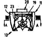
图1是根据本发明实施例的从潮汐汽流中获取能量的设备的前视图;FIG. 1 is a front view of an apparatus for harvesting energy from tidal steam according to an embodiment of the present invention;
图2是图1设备的后视图;Fig. 2 is the rear view of Fig. 1 equipment;
图3(a)(b)(c)(d)(e)和(f)示出了图1设备的组成部件的前视图;Fig. 3 (a) (b) (c) (d) (e) and (f) show the front view of the constituent parts of Fig. 1 equipment;
图4是图1设备的部分截面视图;Figure 4 is a partial sectional view of the device of Figure 1;
图5是图1设备沿A-A线的放大截面视图;Fig. 5 is the enlarged sectional view of Fig. 1 equipment along A-A line;
图6是栓系本发明设备的支撑组件的侧视图;Figure 6 is a side view of the support assembly tethering the apparatus of the present invention;
图7和8分别示出了设备被栓系的方式的平面和侧面视图;Figures 7 and 8 show respectively plan and side views of the manner in which the device is tethered;
图9示出了设备在水体中运转的前视图;Figure 9 shows a front view of the device operating in a body of water;
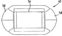
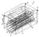
图10和11是从潮汐汽流中获取能量的设备的第二实施例的从上方和下方的等轴视图;Figures 10 and 11 are isometric views from above and below of a second embodiment of an apparatus for harvesting energy from tidal steam;
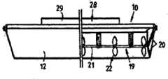
图12、13和14是根据本发明的实施例的图10设备的侧视图和俯视图;Figures 12, 13 and 14 are side and top views of the apparatus of Figure 10 according to an embodiment of the invention;
图15是图10和11的设备沿图13的B-B线的放大纵向截面视图;Figure 15 is an enlarged longitudinal sectional view of the device of Figures 10 and 11 along the line B-B of Figure 13;
图16是图10至15的设备去掉了偏转板并且没有发电机室的上方等轴分解视图;Figure 16 is an exploded isometric view from above of the apparatus of Figures 10 to 15 with the deflection plates removed and without the generator chamber;
图17是图10至15的设备的浮筒的等轴视图;Figure 17 is an isometric view of a buoy of the apparatus of Figures 10 to 15;
图18示出了设备的浮筒和流体管道路或通道之间的关系;Figure 18 shows the relationship between the buoys of the device and the fluid pipelines or channels;
图19是管道和转动体组件的平面视图;Figure 19 is a plan view of the duct and rotor assembly;
图20和21示出了另一管道结构和相应的转动体组件的等轴和平面视图;Figures 20 and 21 show isometric and plan views of another duct structure and corresponding rotor assembly;
图22示出了根据本发明的另一设备的分解视图;以及Figure 22 shows an exploded view of another device according to the invention; and
图23和24示出了图10至15的设备在流动水体内的等轴视图和后视图。Figures 23 and 24 show isometric and rear views of the apparatus of Figures 10 to 15 in a body of flowing water.
具体实施方式Detailed ways
首先根据图1至3,其示出了根据本发明的从潮汐汽流或其它水流中获取能量的设备10,该设备包括壳体组件11,其为双体船结构并且包括一对间隔分开的壳体12。壳体12至少具有锥形船首13(并且优选还具有如图5所示的锥形船尾14)使得壳体组件11能够在水流中朝向船首13或船尾14操作,而不改变壳体组件11的方位。此外,壳体12能够在设备10定位的地方至少部分或全部淹没在水中,为此,每个壳体12提供一个或多个压载箱或压载舱15(见图3(c))。一个或多个泵(未示出)连接到箱或舱15并且可操作地同步向各自的壳体12上的舱或箱15填充水使得壳体12至少部分下沉。箱或舱15还可以被排空水以去除箱或舱15内的水提供的压载重量。Referring firstly to Figures 1 to 3, there is shown an
支承在壳体12之间并且纵向延伸的是中空的流路限定元件或管道16,其限定了具有部分圆形横截面的延伸的细长流路或通道17,流路或通道17在底侧开口。如图1和2、3(a)和(b)所示,元件16如此定位使得它不在壳体12下方延伸并且因此不增加壳体组件11的正常吃水深度。Supported between the
在流路17内转动安装有叶轮组件19(见图4和5),其被径向延伸的支柱20支承使得围绕纵向延伸的轴线转动,支柱20位于壳体组件11的相对端部(并且如果需要的话沿着叶轮组件19间隔定位)。叶轮组件19包括中心固定的细长支承体21和沿着支承体21间隔定位排列的多个叶片组件22。如图1、2、4和5所示,叶片组件22具有的最大直径使得其与流路17的部分环形壁23径向向内相间隔。优选叶片组件22的最大直径为流路17直径的60%-85%。这样有效地限定了叶片组件22的外部直径和流路17的壁23之间的间隙24,以便形成风险效应(venture-like effect)并确保水加速通过间隙24。另外,间隙24允许水中的海洋生命或异物或其它物质通过而不会损坏叶轮组件19。Rotatably mounted within
每个叶片组件22包括多个径向延伸的叶片25。叶片25可以具有固定的选定倾斜度以使得设备在水体中操作时根据预期的水体流速获取最大能量。可选择地,叶片25可以通过支承体21上的调整机构改变倾斜度。这样叶片25的角度能够在满翼(fully feathered)的非操作位置和能够从水流中获取最大能量的位置之间变化。叶片组件22连接到装有轴承的普通驱动轴26(图5中的虚线示出),驱动轴26在支承体21内部纵向延伸。各个叶片组件22的叶片25的倾斜角度能够通过各自的调整机构进行调节以达到轴26的最快转动并由此从水流中获取最大能量。叶片组件22还通过各自的离合器或类似的传动装置(未示出)连接到轴26,离合器或类似的传动装置允许一个叶片组件22相对于其它叶片组件22以不同速度转动,同时允许驱动力从各个叶片组件22传递到轴26上。传动装置可以包括例如液压传动装置或机械传动装置。Each
叶片组件22的叶片25在它们的工作表面上可以具有向外伸出的鳍或类似物以增加从水流传递到叶片组件25的能量。鳍可以减少水脱离叶片25表面的滑移量。The
细长的支承体21适于具有足够的直径以便将水展开并在流路17内形成增加的压力。尽管如此支承体21的直径不应造成船首在操作中的波动。The
如图3(f)所示,通过在流路17的内壁23上提供多个沿圆周分隔开的导向件27以达到获取能量的更高效率,导向件27从流路壁23径向向内突出一短距离并且沿基本上平行于流路17的轴线延伸。导向件27可以防止由于叶轮组件19的转动引起通过流路17的水的螺旋运动,使得更多下游叶片组件22的运转更加高效。As shown in Figure 3 (f), by providing a plurality of circumferentially spaced guides 27 on the
叶轮组件19的轴26经由定向变速箱连接到正确啮合以驱动位于壳体组件11顶部的发电机28。发电机28位于封闭的发电机室29内部,其将发电机28相对于部件进行遮蔽。如果需要冷却发电机28,可以使用位于设备10内的电热交换器或水冷散热系统。发电机28可以是任意已知出售的型号和功率的发动机,基于设备10的尺寸、设备10的使用区域和该区域的可用水流进行选择。The
基于设备10的尺寸和它的可能有不同的潮汐流的目标定位地点,可以要求附加的起动或自身发动能源接合到发电机28以使得发电机28能够启动。在这里的设置中,来自轴26的驱动力通过变速箱提供的驱动链被传送到液压马达/泵组合。来自泵的液压输出供应到液压蓄能器并且第二液压马达与发电机28相配合,接收液压流体的第二液压马达达到预定蓄能器压力就能够使得第二液压马达撞击启动发电机28。一旦撞击启动接合,轴26通过离合系统驱动发电机28使得叶轮组件19的持续转动能够直接通过变速箱驱动发电机28。液压马达驱动系统还会记录流动/驱动方向并且设置得啮合到符合流动方向要求的定向齿轮。Depending on the size of the
漂浮的设备10优选设置为单方向流动系统(河流或摆动系泊处上的单元)使得设备10不需要反转齿轮系统并且依靠流动/压力能够决定是否需要蓄能器和液压马达系统。The floating
如图6至8示出了用于栓系设备10的桩组件30,桩组件30包括可以被打入河床或其它水体中的竖桩31,桩31通常在下游侧支撑竖立的导轨32。转动轮架33附着在导轨32上在竖直方向上沿相反方向运动。轮架33包括定位中心点34,其上连接有保持支柱35,保持支柱35接合到壳体组件11的船首。支柱35通过或连接到桩附近的浮子36,浮子36使得轮架33随着例如潮汐高度变化引起的水平面变化沿着导轨32上下移动,震动吸收器37(见图5)可以设置在壳体组件11的船首和桩30之间,使得由于摆动运动和或与任何无法预料的物质接触所产生的破损风险降到最低。如图8中的虚线所示,另一个导轨32可以设置在桩组件30的相对侧以使其导向另一个轮架33,这样一个设备10可以接合到单个桩组件30的一侧并且一个设备10接合到桩组件30的另一侧,使得一个设备10能够独立于另一个设备10随着各自的轮架33沿着导轨32上下运动。Figures 6 to 8 illustrate a
壳体组件11可以采用不同于上述的设置保持在水的流动/涌流中的方向。例如,壳体组件11能够栓系到摆动系泊处使得船首13(或船尾14)一直指向迎面而来的水流。无论壳体组件11的船首端还是船尾端栓系在位于船前方的桩上都会达到这样的效果。使用这种形式的系泊方式,当潮汐变化时,壳体组件11围绕桩摆动指向水流动方向。The
在另一种设置中,使用上述的壳体组件11具有相似的船首构造和船尾构造的双端部构造,壳体组件11的两端能够固定/栓系在四个桩或柱30之间,桩或柱30为如图6至8所描述的类型,具有通过随着潮汐的上升和下降的浮子的调整而上升和下降的轮架33。根据系泊的形式,多个设备10能够交错或直线定位来使得柱30被多个设备所使用。桩或柱30位于设备10的船首和船尾的各个角处。可选择地,一个桩或柱30可以设置在船首并且一个桩或柱30设置在船尾。由于壳体组件的前方和后方是镜像的,当潮汐到来时,壳体组件11的船首指向流动方向并且当潮汐退去时,船尾14指向流动方向,此时船首13实际上成为壳体组件11的船尾。叶片组件22的叶片25可以在倾斜度上自动反转或基于流动方向按照要求通过本领域已知装置选择性地反转,保证发电机28在任意方向上都能运转。In another arrangement, using the above-described double-ended construction of the
在另一种系泊设置中,设备10可以用相同方式栓系在船系泊浮筒上,或可以包括一个浮筒,设备10通过船首13栓系/固定到河/江的岸边,或者柱和另一个臂上;其以基本直角从壳体组件11固定到岸边。直角臂能够用作组合厚板材通道以易于进入设备10进行维修等。通道/厚板材被铰接以便于随着潮汐上升和下降并且船首绳索也将设备维持在其位置上。In another mooring arrangement, the
如图9所示,当设备10在运转时,壳体组件11被压载使得它可以半淹没地漂浮在水体39中并且随着潮汐上升和下降。壳体12优选通过装满压载箱15充分淹没以降低风或浪的影响并且优选可以淹没到至少达到叶轮组件19的上平面并且最好使得流路或通道元件16完全淹没。压载箱或舱15可以充满或部分充满水使得船在水下定位以保证叶轮组件19完全淹没。如果在低潮时没有水,壳体组件11会坐落在设备10所在的海、河或江的底部,并且当流路或通道元件16位于壳体组件11的底部或船脊骨的上方,它和包含在其内部的叶轮组件19将不会被破坏。当水返回时壳体组件11会随着水平面的上升而上升。As shown in Figure 9, when the
一旦水流通过壳体组件11,壳体组件11的锥形壳体12在船首13(或船尾14)的相对侧面形成锥形狭道38以成为漏斗状并且引导水流入浮子12之间并且通过流路17。引导进入流路17的水接触到叶轮组件19并且由于与叶片组件22相互作用,轴26转动以驱动发电机28。由于流过通道17的可用横截面积因为叶轮组件19在其中而被减小,固有限的区域而形成更大压力/流动以驱动叶片组件22。Once the water flows through the
发电机28可以安装制动器,可以在驱动结束后锁定发电机和叶轮组件19使得无论任何原因都停止转动。The
发电机28产生的电能可以通过电缆传输(经由使用的支柱35和桩31),下降到海床并穿过邻接的陆地到达要求传输能量的区域。The electrical energy generated by the
锌正极可以设置在壳体12上,用作损耗元件以防止老化和生锈或电解。A zinc positive electrode may be provided on the
叶轮组件19可基本上在结构上有变化并且设计得能够获取最大能量。叶轮组件19可以包括任意数量的叶片组件22并且叶片组件22可以是各种各样的设计。The
壳体组件11可以由任意适合的材料例如木材、玻璃加强塑料、铝或任意其它材料或材料的组合制成。叶轮组件和其构件和相关构件适于采用抗腐蚀材料例如不锈钢制成。
根据图10至16,其示出了从潮汐汽流或其他流,尤其是快速流中获取能量的设备40,根据本发明的另一实施例,设备40与图1至9中的设备10同样包括浮力体或漂浮组件41,其包括一对空心浮筒42,其中一个是另一个的镜像。浮筒42具有锥形船首43和船尾44,尽管如此,基于水流的方向船首43可以作为船尾44并且反之亦然。此外浮筒42还具有在图17和18中更清楚示出的纵向延伸的凹面45,其形成基本为圆形截面的通道或流路47的内壁46的组成部分。浮筒42在它们的上表面还具有凹进处48。According to Figures 10 to 16, which show a
如图16所示,一对浮筒42彼此相对设置并且在浮筒42之间设置上方和下方填充部分49和50,填充部分49和50具有与表面45的半径相同的内部曲形壁面51和52(见图15)以形成通道47的环形内壁46的另外部分,并且当其与表面45组合限定了通道47的封闭外围内部(不同于图1至9的设备10的通道或流路结构)。上部填充部分49还可以包括一个或多个基底部54,其跨越相对的凹进处48并且与凹进处48在设备40内限定了适于容纳发电机的发电机室56的扩大的上部凹进舱55(见图10至15)。浮筒42的船首43和44的内部曲面和漂浮组件41的上表面和下表面在漂浮组件41的引导和尾随端限定了进入通道47的引导和尾随端的锥形入口,使得有助于引导水进入通道47。锥形入口可以是截头圆锥体结构的横截面,其远离通道47的相对端部而增大。As shown in FIG. 16, a pair of
浮筒42能够至少部分或全部淹没在设备10所定位的水里,并且一个或多个舱底泵57设置在各个浮筒42内使得从浮筒42抽水以增加浮筒的浮力。另外的一个或多个泵(未示出)用来同时将水泵入浮筒42,浮筒42为压载箱工作,至少部分下沉或淹没浮筒42和设备40。The
设备40还包括位于漂浮组件41的船首和船尾的锥形端部元件58,端部元件58由于密封的空腔体或具有浮力的材料例如泡沫塑料而具有浮力并且形状与常规船首相同。端部58能够基于水相对于漂浮组件41的流动方向吸收波浪的能量并将波浪引导到漂浮组件41的侧面。端部58设置在通道47的上侧并且向外延伸到浮筒42之间并且超过漂浮组件41的船首43和船尾44。The
可分离的防护装置59设置在漂浮体41的引导和尾随端跨越相对的浮筒42,并且防止较大物体或动物进入通道47。防护装置59可以是任意结构,可以简单地形成为在设备40的前部和后部相对的浮筒42之间延伸的横杆,而不必是示出的笼子结构。
叶轮组件60可转动地安装在通道47内(见图15,18和19),其被支承得以围绕纵向延伸轴转动并且位于通道47中央。该实施例中的叶轮组件60包括通过各自的轴63连接或安装在共同的轴63上的一对相对的类似的端部叶轮或转动体61和中央叶轮或转动体62。各个轴63支承在细长的轴承室65内的轴承64中,其通过径向延伸的支柱66安装在通道47的中央,支柱66具有翼形横截面以使得流过通道47的阻力最小。
各个叶轮61(见图18和19)包括外圆环67,中心毂68和径向延伸在毂68和环67之间的多个叶片69。其它叶轮62都是相似结构。环67具有的最大直径使得与通道47的环形壁46径向向内间隔开。优选前部和后部叶轮62的环67的最大直径是通道47的内径的60%-85%,使得在环67和通道47的壁46之间形成间隙70以造成风险效应(venture-like effect),并确保水加速通过间隙70并且进一步允许水中的海洋生物或异物或其它材料通过而不会破坏叶轮组件60。在优选结构中,壁46的内径为1m并且环67的外径为800mm。中央叶轮62的最大直径比引导和尾随叶轮61的直径小。这样可以保持或使得通过通道47的水的动能在通过引导叶轮61之后所损耗的能量恢复。Each impeller 61 (see FIGS. 18 and 19 ) includes an outer
各自的叶轮61和62的叶片69安装成围绕它们的纵向轴转动以使得叶片69的倾斜度改变以适应通过通道47的水流。这样叶片69的角度能够改变或能够在满翼(fully feathered)的非操作位置(此处叶片69基本上平放于沿通道47纵向延伸的径向平面)和在能够从水流中获取最大能量翼位置(feathered position)的任一个面之间变化。叶片69的倾斜度调整机构能够根据通过通道47的水流自动调整,或叶片倾斜度能够选择性地调整,例如通过能进入通道47的不同的调整机构。叶轮的各个叶片69的倾斜度能够被同步调整。The
虽然图18和19示出的通道47在其长度上具有恒定的直径,但可以在其两端部的中间设置窄部或腰部71并且如图20和21所示随着中央叶轮62调整。这样保持间隙70基本上在各个叶轮61和62处相同并且进一步使得通过中央叶轮62的水流加速。While FIGS. 18 and 19
叶轮组件60的轴63通过直角变速箱例如圈和小齿轮组72与向上延伸进入到发电机室56的主输出轴73连接(见图15)。输出轴73通过另一个直角变速箱74和离合器75连接到位于室56内的发电机76。发电机76可以是任意已知出售的型号和功率的发动机,其基于设备10的尺寸、设备10的使用区域和该区域的可用水流进行选择。作为可替换的传动装置,轴63可以通过液压传动连接到发电机76。The
为了防止通过通道47的水由于叶轮组件60的转动形成螺旋运动,可在在通道47内设置沿通道47纵向延伸并且径向向内突出的多个沿圆周间隔开的导向件77。在图22中更清楚地示出了稍微改进的能量获取设备78的形式,其包括具有四个间隔叶轮80的叶轮组件79。导向件77从通道壁46径向向内突出一短距离并且基本上平行于流路47的轴线延伸,确保更多下游转动体80更高效地运转。图23的设备78还包括位于四角的接合凸耳81以利于通过适合的提升装置将设备78提升进入和升出水中并且进一步能够作为栓系索耳用于通过栓系绳82栓系或锚定设备78。To prevent the water passing through the
如图23和24所示,位于水体83中的设备40(或78)与箭头C所指的水流方向保持一致。改变浮筒42的浮力以保证通道47全部淹没在水体83中并且在水平面84下方(见图24)。水流通过通道47会引起叶轮组件49和轴63的转动并且会通过输出轴传递到发电机76用于产生电能,电能可以通过合适的电缆供应到陆地或用于其它用途。As shown in Figures 23 and 24, the device 40 (or 78) located in the body of water 83 is aligned with the direction of water flow indicated by arrow C. The buoyancy of the
上述的能量获取装置可以用作在高水流区域中的可漂浮浮筒,具有延伸到海岸线或其他浮筒的通道。可以设置多个上述设备并且用于维修目的,漂浮组件应该易于漂浮到维修地点。如水位退下一样,设备可以在靠近岸边的地方使用,它能够坐落在河床或类似物上而不会破坏叶轮组件。The energy harvesting device described above may be used as a buoyable buoy in areas of high current, with channels extending to the shoreline or other buoys. Multiples of the above mentioned equipment can be provided and used for maintenance purposes, the floatation assembly should be easy to float to the maintenance site. As the water level recedes, the device can be used close to shore where it can sit on a river bed or the like without damaging the impeller assembly.
上述实施例中的浮筒42可以具有限定浮筒内部和外部表面的外壳并且限定了内部空腔或具有浮筒锥形相对端部的压载箱。浮筒42可以具有任意形状和尺寸。浮筒或浮子之间的水流通道优选具有圆形横截面但也可以是其它形状的横截面。叶轮组件也可以是不同于上述示例中的其它结构并且可以只具有上述一个叶片组件或转动体或多个叶片组件或转动体。The
说明书全文中使用的词语“包括”或“包含”代表存在涉及的特征、整体和部件但不排除存在或附加一个或多个其它特征、整体、部件或其组合。The word "comprising" or "comprises" used throughout the specification represents the presence of the mentioned features, integers and components but does not exclude the presence or addition of one or more other features, integers, components or combinations thereof.
本领域技术人员应该认识到上述实施例的所有变型和改进都落入本发明的权利要求限定的范围和界限内。Those skilled in the art should realize that all the variations and improvements of the above embodiments fall within the scope and limits of the claims of the present invention.
Claims (26)
Applications Claiming Priority (3)
| Application Number | Priority Date | Filing Date | Title |
|---|---|---|---|
| AU2007906923 | 2007-12-19 | ||
| AU2007906923AAU2007906923A0 (en) | 2007-12-19 | Apparatus for extracting energy from flowing water | |
| PCT/AU2008/001887WO2009076726A1 (en) | 2007-12-19 | 2008-12-19 | Apparatus for extracting energy from flowing water |
Publications (2)
| Publication Number | Publication Date |
|---|---|
| CN101970854Atrue CN101970854A (en) | 2011-02-09 |
| CN101970854B CN101970854B (en) | 2014-11-26 |
Family
ID=40795125
Family Applications (1)
| Application Number | Title | Priority Date | Filing Date |
|---|---|---|---|
| CN200880126652.2AExpired - Fee RelatedCN101970854B (en) | 2007-12-19 | 2008-12-19 | Apparatus for extracting energy from water flow |
Country Status (5)
| Country | Link |
|---|---|
| US (1) | US8696301B2 (en) |
| EP (1) | EP2235360A1 (en) |
| CN (1) | CN101970854B (en) |
| AU (1) | AU2008338257B2 (en) |
| WO (1) | WO2009076726A1 (en) |
Cited By (6)
| Publication number | Priority date | Publication date | Assignee | Title |
|---|---|---|---|---|
| CN104033322A (en)* | 2013-03-08 | 2014-09-10 | 杭州林黄丁新能源研究院有限公司 | Horizontal type generator device |
| CN106523249A (en)* | 2016-11-29 | 2017-03-22 | 贵州电网有限责任公司电力科学研究院 | Branch micro-water-head floating type hydraulic electro-generating device of cascade hydropower station |
| CN113494414A (en)* | 2021-09-08 | 2021-10-12 | 四川大学 | Sea wave generator |
| US11353001B1 (en)* | 2021-04-30 | 2022-06-07 | Sitkana Inc. | Hydrokinetic generator |
| WO2022161494A1 (en)* | 2021-01-29 | 2022-08-04 | 李庆森 | Energy extraction device in river runner water |
| CN116331405A (en)* | 2023-05-26 | 2023-06-27 | 烟台威浮海洋科技有限公司 | Ship generating power by means of water flow |
Families Citing this family (11)
| Publication number | Priority date | Publication date | Assignee | Title |
|---|---|---|---|---|
| WO2011008153A1 (en)* | 2009-07-17 | 2011-01-20 | Ehmberg Solutions Ab | Offshore energy storage device |
| DE102010015534A1 (en) | 2010-04-16 | 2011-10-20 | Voith Patent Gmbh | Flow power plant and method for its operation |
| EP2388472A1 (en)* | 2010-05-19 | 2011-11-23 | Hydrosub-Energy S.r.l. | Submerged hydroelectric power generator with float assembly |
| US20140145443A1 (en)* | 2010-10-21 | 2014-05-29 | Langlee Wave Power As | Wave power device with generator |
| WO2012156734A1 (en)* | 2011-05-16 | 2012-11-22 | Tidepod Limited | A submersible structure adapted to host tidal energy converters |
| WO2016147938A1 (en)* | 2015-03-13 | 2016-09-22 | 株式会社ベルシオン | Water wheel device |
| JP6681662B2 (en)* | 2015-03-13 | 2020-04-15 | Ntn株式会社 | Turbine equipment |
| US20170353081A1 (en)* | 2016-06-06 | 2017-12-07 | Salvatore Deiana | Multihull barge generator |
| GB2552950B (en)* | 2016-08-10 | 2018-10-03 | Verderg Renewable Energy Ltd | Bidirectional system and apparatus for generating power |
| IL250954B (en)* | 2017-03-06 | 2019-08-29 | Netta Weinroth | A turbine system for producing electrical energy and method therefor |
| CN112808475A (en)* | 2020-12-24 | 2021-05-18 | 厦门英仕卫浴有限公司 | Water-saving dynamic water outlet device |
Citations (9)
| Publication number | Priority date | Publication date | Assignee | Title |
|---|---|---|---|---|
| US583355A (en)* | 1897-05-25 | barton | ||
| US1368454A (en)* | 1919-08-11 | 1921-02-15 | Johan J Rebman | Current-motor |
| DE814879C (en)* | 1948-11-19 | 1951-09-27 | Oswald Berner | Power plant |
| US4446378A (en)* | 1981-07-02 | 1984-05-01 | Jose Martinez Parra | System for the generation of electrical energy by utilizing the kinetic energy of seawater |
| DE3246558A1 (en)* | 1982-12-16 | 1984-07-05 | Martin 4790 Paderborn Schatta | Turbo engine, especially as a water and wind turbine with cam-controlled surfaces of revolution |
| US5281856A (en)* | 1989-11-15 | 1994-01-25 | Tibor Kenderi | Water current energy converter |
| CN2931838Y (en)* | 2006-07-04 | 2007-08-08 | 朱晴平 | Blade-rotating hydropower ship |
| CN101046184A (en)* | 2006-03-31 | 2007-10-03 | 海卓尔有限公司 | Waterwheel |
| CN200975312Y (en)* | 2006-11-28 | 2007-11-14 | 廖伯成 | Non-dam scattering water electric generating apparatus |
Family Cites Families (15)
| Publication number | Priority date | Publication date | Assignee | Title |
|---|---|---|---|---|
| US1071225A (en)* | 1913-02-21 | 1913-08-26 | Ernst R Giffhorn | Wave-motor. |
| US1396609A (en)* | 1920-05-04 | 1921-11-08 | Said George P A Weisenborn | Current or tide motor |
| US3883750A (en)* | 1974-01-30 | 1975-05-13 | Natural Energy Systems Inc | Method and apparatus for generating power from wind currents |
| US4248044A (en)* | 1978-05-15 | 1981-02-03 | Woodilla Marvin F | Apparatus for wave power generation utilizing large mass dynamic energy absorption |
| US4213734A (en)* | 1978-07-20 | 1980-07-22 | Lagg Jerry W | Turbine power generator |
| US4478166A (en)* | 1980-12-22 | 1984-10-23 | Sorensen George C | Boat |
| US4649851A (en)* | 1985-09-12 | 1987-03-17 | April Edward P | High speed power boat for calm and rough seaways |
| US5522333A (en)* | 1994-05-16 | 1996-06-04 | Thomas G. Lang | Catamaran boat with planing pontoons |
| US5497722A (en)* | 1994-09-07 | 1996-03-12 | English, Sr.; Charles | Keelless concave hull |
| US5603280A (en)* | 1994-12-16 | 1997-02-18 | Shackelford, Jr.; Francis H. | Boat Mooring apparatus |
| US6806586B2 (en)* | 1999-10-06 | 2004-10-19 | Aloys Wobben | Apparatus and method to convert marine current into electrical power |
| US6638005B2 (en)* | 2002-01-17 | 2003-10-28 | John W. Holter | Coaxial wind turbine apparatus having a closeable air inlet opening |
| US7322307B1 (en)* | 2003-04-25 | 2008-01-29 | Perry George J | Buoyant bumper system |
| US7116005B2 (en)* | 2005-02-16 | 2006-10-03 | Corcoran Iii James John | Tidal/wave flow electrical power generation system |
| WO2008115558A1 (en)* | 2007-03-20 | 2008-09-25 | Zeuner Kenneth W | System and method for harvesting electrical power from marine current using turbines |
- 2008
- 2008-12-19EPEP08863290Apatent/EP2235360A1/ennot_activeWithdrawn
- 2008-12-19USUS12/808,780patent/US8696301B2/enactiveActive
- 2008-12-19AUAU2008338257Apatent/AU2008338257B2/ennot_activeCeased
- 2008-12-19CNCN200880126652.2Apatent/CN101970854B/ennot_activeExpired - Fee Related
- 2008-12-19WOPCT/AU2008/001887patent/WO2009076726A1/enactiveApplication Filing
Patent Citations (9)
| Publication number | Priority date | Publication date | Assignee | Title |
|---|---|---|---|---|
| US583355A (en)* | 1897-05-25 | barton | ||
| US1368454A (en)* | 1919-08-11 | 1921-02-15 | Johan J Rebman | Current-motor |
| DE814879C (en)* | 1948-11-19 | 1951-09-27 | Oswald Berner | Power plant |
| US4446378A (en)* | 1981-07-02 | 1984-05-01 | Jose Martinez Parra | System for the generation of electrical energy by utilizing the kinetic energy of seawater |
| DE3246558A1 (en)* | 1982-12-16 | 1984-07-05 | Martin 4790 Paderborn Schatta | Turbo engine, especially as a water and wind turbine with cam-controlled surfaces of revolution |
| US5281856A (en)* | 1989-11-15 | 1994-01-25 | Tibor Kenderi | Water current energy converter |
| CN101046184A (en)* | 2006-03-31 | 2007-10-03 | 海卓尔有限公司 | Waterwheel |
| CN2931838Y (en)* | 2006-07-04 | 2007-08-08 | 朱晴平 | Blade-rotating hydropower ship |
| CN200975312Y (en)* | 2006-11-28 | 2007-11-14 | 廖伯成 | Non-dam scattering water electric generating apparatus |
Cited By (7)
| Publication number | Priority date | Publication date | Assignee | Title |
|---|---|---|---|---|
| CN104033322A (en)* | 2013-03-08 | 2014-09-10 | 杭州林黄丁新能源研究院有限公司 | Horizontal type generator device |
| CN106523249A (en)* | 2016-11-29 | 2017-03-22 | 贵州电网有限责任公司电力科学研究院 | Branch micro-water-head floating type hydraulic electro-generating device of cascade hydropower station |
| WO2022161494A1 (en)* | 2021-01-29 | 2022-08-04 | 李庆森 | Energy extraction device in river runner water |
| US11353001B1 (en)* | 2021-04-30 | 2022-06-07 | Sitkana Inc. | Hydrokinetic generator |
| CN113494414A (en)* | 2021-09-08 | 2021-10-12 | 四川大学 | Sea wave generator |
| CN116331405A (en)* | 2023-05-26 | 2023-06-27 | 烟台威浮海洋科技有限公司 | Ship generating power by means of water flow |
| CN116331405B (en)* | 2023-05-26 | 2023-09-05 | 北京威浮科技有限责任公司 | Ship generating power by means of water flow |
Also Published As
| Publication number | Publication date |
|---|---|
| AU2008338257B2 (en) | 2014-03-27 |
| WO2009076726A1 (en) | 2009-06-25 |
| US20100259048A1 (en) | 2010-10-14 |
| EP2235360A1 (en) | 2010-10-06 |
| US8696301B2 (en) | 2014-04-15 |
| CN101970854B (en) | 2014-11-26 |
| AU2008338257A1 (en) | 2009-06-25 |
Similar Documents
| Publication | Publication Date | Title |
|---|---|---|
| CN101970854A (en) | Devices that harvest energy from water flow | |
| JP5242135B2 (en) | Water current generator | |
| US8350396B2 (en) | Water-current paddlewheel-based energy-generating unit having a tapered partial covering structure | |
| US7607862B2 (en) | Shoaling water energy conversion device | |
| US7291936B1 (en) | Submersible electrical power generating plant | |
| ES2243756T3 (en) | UNDERWATER TUBBED TURBINE. | |
| EP2516843B1 (en) | Device of a power plant | |
| CN102203408A (en) | Underwater turbine with winged diffuser for increased flow | |
| JP2014508881A (en) | Hydroelectric generator | |
| US7770390B2 (en) | Configurations and methods for wave energy extraction | |
| CN108603481B (en) | Wide wave spectrum wave energy recovery device | |
| KR20100135010A (en) | Underwater Power Generation Device Using Underwater Floating Rotator | |
| TW201617524A (en) | Ocean current power generation device | |
| GB2487448A (en) | Hydro-kinetic Water Turbine Duct | |
| KR101623709B1 (en) | Water Turbine Structure for Generation Using Tide Current | |
| JP2001221142A (en) | Converter for energy of water power, wave power and wind power | |
| GB2400413A (en) | Current or tide power generator with endless belt supported on a floating hull | |
| JP2011196361A (en) | Floating power-generating device | |
| CN201818425U (en) | vessel | |
| JP2009174510A (en) | Annular floating structure turning on sea | |
| KR101717425B1 (en) | Power Generators using currents in the Pending state | |
| KR101671113B1 (en) | Tidal power generation device | |
| KR101936696B1 (en) | Ship type tidal power generator | |
| GB2456833A (en) | Tilting wave energy device | |
| GB2419383A (en) | Endless loop wave generation device and marine propulsion unit |
Legal Events
| Date | Code | Title | Description |
|---|---|---|---|
| C06 | Publication | ||
| PB01 | Publication | ||
| C10 | Entry into substantive examination | ||
| SE01 | Entry into force of request for substantive examination | ||
| C14 | Grant of patent or utility model | ||
| GR01 | Patent grant | ||
| CF01 | Termination of patent right due to non-payment of annual fee | Granted publication date:20141126 Termination date:20161219 | |
| CF01 | Termination of patent right due to non-payment of annual fee |