CN101970180B - Lead wire part for automatic nail gun - Google Patents
Lead wire part for automatic nail gunDownload PDFInfo
- Publication number
- CN101970180B CN101970180BCN2009801086276ACN200980108627ACN101970180BCN 101970180 BCN101970180 BCN 101970180BCN 2009801086276 ACN2009801086276 ACN 2009801086276ACN 200980108627 ACN200980108627 ACN 200980108627ACN 101970180 BCN101970180 BCN 101970180B
- Authority
- CN
- China
- Prior art keywords
- cam
- lead
- frame
- wire
- cutout
- Prior art date
- Legal status (The legal status is an assumption and is not a legal conclusion. Google has not performed a legal analysis and makes no representation as to the accuracy of the status listed.)
- Expired - Fee Related
Links
Images


Classifications
- B—PERFORMING OPERATIONS; TRANSPORTING
- B25—HAND TOOLS; PORTABLE POWER-DRIVEN TOOLS; MANIPULATORS
- B25C—HAND-HELD NAILING OR STAPLING TOOLS; MANUALLY OPERATED PORTABLE STAPLING TOOLS
- B25C5/00—Manually operated portable stapling tools; Hand-held power-operated stapling tools; Staple feeding devices therefor
- B25C5/06—Manually operated portable stapling tools; Hand-held power-operated stapling tools; Staple feeding devices therefor without provision for bending the ends of the staples on to the work
Landscapes
- Engineering & Computer Science (AREA)
- Mechanical Engineering (AREA)
- Portable Nailing Machines And Staplers (AREA)
- Dovetailed Work, And Nailing Machines And Stapling Machines For Wood (AREA)
Abstract
Description
Translated fromChinese技术领域technical field
本发明涉及自动钉枪的领域,更具体的,涉及用于相对于要被打钉的电线或电缆在该枪中安置U形钉的导线部部件。The present invention relates to the field of automatic nail guns, and more particularly, to a lead part assembly for positioning a staple in the gun relative to a wire or cable to be nailed.
相关技术的说明Description of related technologies
钉枪是众所周知的适合于驱动U形钉进入工件之内的手持式工具。爱洛紧固件有限公司(Arrow Fastener Company)制造和销售很多型号的这种装置,包括以
已知为钉枪设置一个导线部,例如美国专利No.5,884,829中所公开的,其被转让给爱洛紧固件有限公司并通过引用结合在这里。导线部是一种具有适合环绕电线或电缆的表面的部件,安置钉枪以使U形钉被可靠地驱动到电线或电缆上,从而将U形钉固定到工件上。在电线或电缆的任一侧上的表面典型地被安置为靠着要被打钉的表面。It is known to provide a lead section for a nail gun, such as disclosed in US Patent No. 5,884,829, assigned to Arlo Fasteners, Inc. and incorporated herein by reference. The lead portion is a part having a surface adapted to wrap around a wire or cable, and the nail gun is positioned so that the staple is reliably driven onto the wire or cable, thereby securing the staple to a workpiece. The surfaces on either side of the wire or cable are typically positioned against the surface to be nailed.
由于钉枪技术已经被改进,已经添加了许多所希望的零件。安置在钉驱动器附近并且适合于直接照亮被打钉的表面的LED很受欢迎。同样已知配备具有被动式的安全装置的钉枪。例如,在爱洛紧固件有限公司的CT 50TM中,安全部件是在驱动器前面从枪的底部突出的平面竖直定向的部件。平面部件控制一个开关,以使枪只在完全地按下安全部件的时候,即,当枪的底部被安置为靠着要被打钉的表面的时候,才可以射击。As nail gun technology has been improved, many desired parts have been added. LEDs positioned near the nail driver and adapted to directly illuminate the surface being nailed are popular. Nail guns with passive safety devices are likewise known. For example, in the
LED和安全部件两者都有利地安置在钉驱动器的前面,以便不妨碍枪的操作,特别是不妨碍钉驱动器的操作。因为钉驱动器前面的可用空间受限制,所以为设置与这些部件结合在一起的导线部提出了技术挑战。Both the LED and the safety feature are advantageously placed in front of the staple driver so as not to interfere with the operation of the gun, especially the staple driver. Because the space available in front of the staple driver is limited, a technical challenge is presented for providing the lead portion in combination with these components.
因而,本发明的一个目的是提供一种用于钉枪的导线部,该导线部在钉枪前端的低矮型框架中,该导线部可以被用户收缩、并且可以与诸如LED和安全部件的其他部件以节省空间的方式结合在一起。Accordingly, it is an object of the present invention to provide a lead portion for a nail gun in a low profile frame at the front end of the nail gun that can be retracted by the user and can be integrated with other components such as LEDs and safety components. Other parts are combined in a space-saving manner.
发明内容Contents of the invention
在一个方面中,本发明是设置在钉枪上的导线部设备,该钉枪在其前端具有钉驱动器(诸如,没有限制,由爱洛紧固件有限公司制造的CT-50TM型号)。用于导线部的框架被安置在钉驱动器的前面。该框架容纳凸轮开关、凸轮轴和凸轮,并且凸轮开关可以被移动以转动凸轮。在框架中的基本上平面的导线部具有适合于被安置在电线或电缆上的第一切口、和适合于安放凸轮的第二切口。凸轮被安置成可在第二切口内转动,从而使导线部在第一位置和第二位置之间移动,在第一位置中,第一切口不从钉枪伸出,在第二位置中,第一切口从钉枪伸出。在较佳实施例中,钉枪设置有基本上平面的安全部件,该安全部件具有孔,凸轮轴经过该孔,孔被拉长以使安全部件可以在框架中在竖直方向上滑动。In one aspect, the invention is a lead device provided on a nail gun having a staple driver at its front end (such as, without limitation, model CT-50™ manufactured by Arlo Fasteners, Inc.). A frame for the lead section is positioned in front of the staple driver. The frame houses the cam switch, camshaft and cam, and the cam switch can be moved to turn the cam. The substantially planar lead portion in the frame has a first notch adapted to be seated on a wire or cable, and a second notch adapted to seat a cam. The cam is arranged to rotate within the second notch so that the wire portion moves between a first position and a second position in which the first notch does not protrude from the nailer and in the second position , the first cut protruding from the nailer. In a preferred embodiment, the nail gun is provided with a substantially planar safety member having a hole through which the camshaft passes, the hole being elongated so that the safety member can slide vertically in the frame.
在更佳的实施例中,框架设置有发光二极管。In a more preferred embodiment, the frame is provided with light emitting diodes.
附图说明Description of drawings
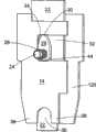
图1是装有根据本发明的导线部设备的钉枪的立体图。Fig. 1 is a perspective view of a nail gun equipped with a lead part device according to the present invention.
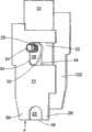
图2是导线部框架的详图。Fig. 2 is a detailed view of the frame of the lead part.
图3是导线部在伸出位置中的导线部框架的详图。Figure 3 is a detail view of the lead portion frame in the extended position of the lead portion.
图4是导线部凸轮系统机构的内部部件的详图。Figure 4 is a detailed view of the internal components of the lead camming mechanism.
图5是导线部凸轮系统机构在伸出并锁定位置中的内部部件的详图。Figure 5 is a detailed view of the internal components of the lead camming mechanism in the extended and locked position.
具体实施方式Detailed ways
除非另有说明,这里参考钉枪的标准方位来使用方向。因而,手柄在装置的顶部,并且朝顶部的方向是“上”。钉驱动器(未显示)被竖直地定向,朝枪的“前部”设置;钉从钉枪的“底部”出来,并且朝底部的方向是“下”,等等。Unless otherwise stated, directions are used here with reference to the standard orientation of the nail gun. Thus, the handle is at the top of the device, and the direction towards the top is "up". Nail drivers (not shown) are oriented vertically, set toward the "front" of the gun; nails come out of the "bottom" of the nail gun and are oriented "down" toward the bottom, and so on.
在图1显示的实施例中,钉枪10在底部包括位于钉枪的前端的插入件12。钉驱动器,有时称为“刀”(未显示),是位于插入件后面的竖直的部件,当扣动扳机时,钉驱动器将钉驱动到枪的外部。In the embodiment shown in FIG. 1 , the nailer 10 includes an
参见图2的详图,插入件12包括框架18,框架18可以设置有槽以便引导导线部14和安全部件22。框架还包括用于凸轮开关20的空间。Referring to the detail view of FIG. 2 , the
凸轮开关可以是任何形状,只要它能够被配置为移动导线部14。在较佳实施例中,凸轮开关的至少一部分是弓形形状,并且凸轮被安装在框架中的相应形状的弓形凹部中。例如,开关可以是圆形并且被安装在圆形凹部中,如图2所示。The cam switch may be of any shape as long as it can be configured to move the
在显示的实施例中,凸轮开关可在分别对应于导线部14的第一位置和第二位置的第一位置和第二位置之间转动,以致导线部如图2所示不从钉枪的底部伸出,或者从钉枪底部伸出,并且准备使用。这能够在不希望对电缆或电线打钉的情况下,不用导线部,而诸如用钉子(典型地5/8”钉子)或用U形钉,来方便地使用钉枪。在那些情况下,导线部被设定在收缩位置。In the embodiment shown, the cam switch is rotatable between a first position and a second position respectively corresponding to the first position and the second position of the
框架可以具有在框架的前部上的一个后开口(open back)以及中心通道,以便安放凸轮开关20以及副框架52,该副框架52以紧凑的低矮型(low-profile)方式容纳LED 50。“低矮型”在这里意指框架从后到前的总高度小于25毫米,更好地小于20毫米并且最好小于15毫米。The frame may have an open back and center channel on the front of the frame to accommodate the cam switch 20 and the
导线部部件14更好是平面的,以便能够被收纳在低矮型的框架中。导线部包括第一切口36(图4中所示)和适合于安放凸轮28的第二切口32,第一切口36具有开口端,在使用电线或电缆时,该开口端适合于安置在电线或电缆上。第二切口在凸轮的一侧上具有闭合的表面34(见图4),该闭合的表面34防止凸轮在顺时针方向或者逆时针方向上的转动经过该表面34,而在凸轮的相对的一侧上,第二切口32具有允许凸轮28转动的余地。在显示的实施例中,第二切口的与闭合侧相对的一侧是开口的,并且凸轮能够从第一位置到第二位置转动略微大于180度。The
第二切口的闭合的表面34可以设置有圆形角,以致该切口在闭合端比在开口端稍微宽一些。这有助于在第二切口的角落中安置凸轮的支撑面30从而执行以下描述的锁定功能。The closed
结合图4图解用于根据本发明的导线部的凸轮机构的操作。在图4的较佳实施例中,已经移去了凸轮开关从而露出装配在后板120上的凸轮轴24、弹簧26和凸轮28。凸轮可以具有适合于该用途的任何形状,包括在图4的较佳实施例中显示的卵形形状。在收缩或第一位置中,凸轮28的支撑面30抵靠第二切口32的顶面。为了在第一(收缩)位置锁定导线部,略微转动凸轮经过导线部的纵轴,以使凸轮的纵轴相对于导线部14的纵轴形成一个小角度,稍微朝第二切口的闭合侧倾斜。在导线部的第二(伸出)位置中获得类似的锁定功能,其中,凸轮被转动略微大于180度,凸轮的支撑面30抵靠第二切口的底面。通过将支撑面30停留在切口的角落中,以使凸轮的纵轴相对于导线部的纵轴成一个角度,这样就不能借助于沿着箭头F方向的作用力来移动导线部,除非通过移动凸轮开关20来再次移动凸轮。这在图5中被最好地显示。The operation of the cam mechanism for the wire part according to the present invention is illustrated with reference to FIG. 4 . In the preferred embodiment of FIG. 4 , the cam switch has been removed to expose the
通过加宽第二切口中的闭合的表面34的角部,诸如通过使角部变圆,来改善锁定机构。依据需要多大的凸轮来使导线部在第二位置从钉枪突出期望的量,来确定第二切口的尺寸。虽然不是关键的,但是第二切口的竖直高度可以在大约8.0毫米到大约11.0毫米的范围中,并且在第二切口的闭合端处,即,在最宽点处的顶壁和底壁之间的距离,可以比在第二切口的闭合端的相对侧或开口侧处的距离大大约0.1毫米到大约0.5毫米。The locking mechanism is improved by widening the corners of the closed
第一切口36可以形成有限定第一切口的相对侧的叉状物38。限定第一切口的两个叉状物之间的距离不是特别关键的,并且例如可以在大约6.0毫米到大约8.0毫米的范围内。在研究的实施例中,发现7.0毫米的宽度适合于该用途。同样地,从切口的顶部到叉状物的底端的距离不受限制。该距离可以方便地在大约5.0到7.0毫米的范围内,例如6.2毫米。切口的顶部可以是任何形状,诸如弓形形状。在附图中,切口的顶部基本上是半圆形。通常被用于由爱洛紧固件有限公司制造的CT-50TM的U形钉将同样被用于适合于如本发明的导线部的型号,并且可以相应地设计第一切口的尺寸。The
在实施例中,钉枪可以设置有安全部件22,安全部件22以已知的方式(未显示)被操作地连接到枪体中的部件,以使枪不能射击,除非按下安全部件。为了利用这里描述的导线部和框架来收纳安全部件22的操作,安全部件22设置有孔44,凸轮轴经过该孔44。该孔被有点拉长,允许安全部件上下移动,而不影响导线部。(在图4和图5中只看见孔44的一部分,因为导线部使视图不明显)。In an embodiment, the nail gun may be provided with a
图2描绘一较佳实施例,其中,框架18设置有中心通道,该中心通道容纳凸轮开关20、包括LED 50的LED副框架52,而且收纳如上所述的导线部和凸轮部件。可以以低矮型的形式设置所有部件,低矮型的形式具有小于20毫米的高度,更好地是小于15毫米,这允许安全部件22、LED 50和导线部14全部以接近于钉驱动器的方式被安置。Figure 2 depicts a preferred embodiment in which the
以上较佳实施例的说明连同附图被用于说明用途,而不被视为限制由附加的权利要求书所限定的本发明。The above description of the preferred embodiments together with the accompanying drawings are for illustrative purposes and are not to be considered as limiting the invention as defined by the appended claims.
Claims (5)
Translated fromChineseApplications Claiming Priority (3)
| Application Number | Priority Date | Filing Date | Title |
|---|---|---|---|
| US3475208P | 2008-03-07 | 2008-03-07 | |
| US61/034,752 | 2008-03-07 | ||
| PCT/US2009/030410WO2009111094A1 (en) | 2008-03-07 | 2009-01-08 | Wire guide for an automatic staple gun |
Publications (2)
| Publication Number | Publication Date |
|---|---|
| CN101970180A CN101970180A (en) | 2011-02-09 |
| CN101970180Btrue CN101970180B (en) | 2013-03-06 |
Family
ID=40416926
Family Applications (1)
| Application Number | Title | Priority Date | Filing Date |
|---|---|---|---|
| CN2009801086276AExpired - Fee RelatedCN101970180B (en) | 2008-03-07 | 2009-01-08 | Lead wire part for automatic nail gun |
Country Status (8)
| Country | Link |
|---|---|
| US (1) | US8413865B2 (en) |
| EP (2) | EP2650088B1 (en) |
| CN (1) | CN101970180B (en) |
| AU (1) | AU2009220105C1 (en) |
| CA (1) | CA2717501C (en) |
| MX (1) | MX2010009813A (en) |
| NZ (1) | NZ587759A (en) |
| WO (1) | WO2009111094A1 (en) |
Families Citing this family (17)
| Publication number | Priority date | Publication date | Assignee | Title |
|---|---|---|---|---|
| EP2650088B1 (en) | 2008-03-07 | 2015-04-01 | Arrow Fastener Company, LLC | Wire guide for an automatic staple gun |
| US8240535B2 (en)* | 2010-11-15 | 2012-08-14 | Arrow Fastener Co., Llc | Staple gun wire guide |
| US8915416B2 (en)* | 2012-02-29 | 2014-12-23 | Tsung-Wen Huang | Nail guiding device for nailers |
| TW201417967A (en)* | 2012-11-05 | 2014-05-16 | Jann Yei Industry Co Ltd | Cable-pressing mechanism of nail gun |
| USD717147S1 (en) | 2014-04-22 | 2014-11-11 | Arrow Fasterner Co., LLC | Fastening tool |
| USD717148S1 (en) | 2014-04-22 | 2014-11-11 | Arrow Fastener Co., Llc | Fastening tool |
| USD727125S1 (en) | 2014-05-02 | 2015-04-21 | Arrow Fastener Co., Llc | Fastening tool |
| USD723894S1 (en) | 2014-05-02 | 2015-03-10 | Arrow Fastener Co., Llc | Fastening tool |
| WO2016105256A1 (en) | 2014-12-22 | 2016-06-30 | Husqvarna Ab | Fastener retention device for a guard cover |
| USD774034S1 (en)* | 2015-07-30 | 2016-12-13 | Synaptive Medical (Barbados) Inc. | Rapid registration scanner |
| US10442067B2 (en)* | 2017-01-06 | 2019-10-15 | Worktools, Inc. | Fastening tool wire guide |
| US11090794B2 (en)* | 2018-01-22 | 2021-08-17 | Black & Decker Inc. | Cable staple tool assembly with a self-adjusting cable guide |
| US10821587B2 (en)* | 2018-03-30 | 2020-11-03 | Black & Decker Inc. | Stapling tool assembly including a wire alignment contact trip |
| USD900575S1 (en) | 2018-09-26 | 2020-11-03 | Milwaukee Electric Tool Corporation | Powered fastener driver |
| CN112060013B (en)* | 2019-06-11 | 2022-02-22 | 丰民金属工业股份有限公司 | Nail gun |
| US12202112B2 (en) | 2021-01-20 | 2025-01-21 | Milwaukee Electric Tool Corporation | Powered fastener driver |
| EP4281253A4 (en) | 2021-01-20 | 2024-11-27 | Milwaukee Electric Tool Corporation | ELECTRIC FIXING ELEMENT DRIVE DEVICE |
Citations (4)
| Publication number | Priority date | Publication date | Assignee | Title |
|---|---|---|---|---|
| US4552296A (en)* | 1983-10-19 | 1985-11-12 | Wang Sheng | Stapling gun |
| US5884829A (en)* | 1996-10-23 | 1999-03-23 | Arrow Fastener Co., Inc. | Dual purpose staple gun tacker |
| US6131788A (en)* | 1998-12-09 | 2000-10-17 | Worktools, Inc. | Built-in extendible staple gun wire guide |
| CN2550137Y (en)* | 2002-05-17 | 2003-05-14 | 陈东益 | Nailer clip wire sheath |
Family Cites Families (22)
| Publication number | Priority date | Publication date | Assignee | Title |
|---|---|---|---|---|
| US3510043A (en) | 1967-05-22 | 1970-05-05 | Larson Co Charles O | Stapling machine |
| US4087035A (en)* | 1976-12-08 | 1978-05-02 | Everette Harmon | Attachment for stapling gun |
| DE3533840A1 (en)* | 1985-09-23 | 1987-04-02 | Bosch Gmbh Robert | POWERFUL WRAPPING DEVICE, IN PARTICULAR FOR STAPLES |
| US4805824A (en)* | 1985-10-01 | 1989-02-21 | Erickson Gary W | Apparatus for attaching cable to a surface |
| US4928867A (en)* | 1987-12-21 | 1990-05-29 | Jensen Mark B | System for positioning fasteners |
| US5094380A (en) | 1989-10-13 | 1992-03-10 | Duo-Fast Corporation | Guide for fastener driving tool |
| US5014897A (en) | 1989-11-20 | 1991-05-14 | Briggs & Stratton Corporation | Staple gun driver guide assembly |
| US5491899A (en) | 1992-06-25 | 1996-02-20 | Stihl Andreas | Tensioning arrangement for a saw chain |
| US5826853A (en) | 1996-08-26 | 1998-10-27 | Sandt Technology, Ltd. | Post protector |
| US5735444A (en) | 1996-09-23 | 1998-04-07 | Arrow Fastener Co., Inc. | Insulated staple driving system |
| US5931364A (en) | 1997-06-25 | 1999-08-03 | Acme Staple Company, Inc. | Fastening tool for securing an object to a substrate |
| DE60031822T2 (en)* | 2000-04-20 | 2007-09-13 | WorkTools, Inc., Chatsworth | Wire guide for stapling gun |
| US6393711B1 (en)* | 2000-12-18 | 2002-05-28 | Todd Freund | Siding gauging tool |
| US7011242B2 (en) | 2001-12-07 | 2006-03-14 | Acme Staple Company, Inc. | Coated staple and fastening tool for the same |
| US7562801B2 (en)* | 2005-08-22 | 2009-07-21 | The Stanley Works | Stapler with guide |
| US7540400B2 (en)* | 2006-01-06 | 2009-06-02 | Staples The Office Superstore, Llc | Stapler having a moveable strike plate with lockout mechanism |
| TWM297298U (en)* | 2006-01-09 | 2006-09-11 | Li-Rung Jeng | Pressing line structure for nailing tool |
| JP4968518B2 (en)* | 2007-04-03 | 2012-07-04 | 日立工機株式会社 | Driving machine |
| TW200920562A (en)* | 2007-11-02 | 2009-05-16 | Jann Yei Industry Co Ltd | Staple gun safety device |
| EP2650088B1 (en) | 2008-03-07 | 2015-04-01 | Arrow Fastener Company, LLC | Wire guide for an automatic staple gun |
| US7739807B2 (en)* | 2008-05-09 | 2010-06-22 | Kevin Anthony Grant | Siding gauge device for staple gun |
| US8240535B2 (en)* | 2010-11-15 | 2012-08-14 | Arrow Fastener Co., Llc | Staple gun wire guide |
- 2009
- 2009-01-08EPEP13163897.5Apatent/EP2650088B1/ennot_activeNot-in-force
- 2009-01-08CNCN2009801086276Apatent/CN101970180B/ennot_activeExpired - Fee Related
- 2009-01-08AUAU2009220105Apatent/AU2009220105C1/ennot_activeCeased
- 2009-01-08USUS12/920,395patent/US8413865B2/enactiveActive
- 2009-01-08MXMX2010009813Apatent/MX2010009813A/enactiveIP Right Grant
- 2009-01-08NZNZ587759Apatent/NZ587759A/ennot_activeIP Right Cessation
- 2009-01-08EPEP09716995.7Apatent/EP2268455B1/ennot_activeNot-in-force
- 2009-01-08CACA2717501Apatent/CA2717501C/ennot_activeExpired - Fee Related
- 2009-01-08WOPCT/US2009/030410patent/WO2009111094A1/enactiveApplication Filing
Patent Citations (4)
| Publication number | Priority date | Publication date | Assignee | Title |
|---|---|---|---|---|
| US4552296A (en)* | 1983-10-19 | 1985-11-12 | Wang Sheng | Stapling gun |
| US5884829A (en)* | 1996-10-23 | 1999-03-23 | Arrow Fastener Co., Inc. | Dual purpose staple gun tacker |
| US6131788A (en)* | 1998-12-09 | 2000-10-17 | Worktools, Inc. | Built-in extendible staple gun wire guide |
| CN2550137Y (en)* | 2002-05-17 | 2003-05-14 | 陈东益 | Nailer clip wire sheath |
Also Published As
| Publication number | Publication date |
|---|---|
| MX2010009813A (en) | 2010-11-30 |
| EP2650088A3 (en) | 2014-03-26 |
| EP2268455B1 (en) | 2013-04-17 |
| AU2009220105A1 (en) | 2009-09-11 |
| EP2650088B1 (en) | 2015-04-01 |
| CN101970180A (en) | 2011-02-09 |
| NZ587759A (en) | 2013-04-26 |
| US8413865B2 (en) | 2013-04-09 |
| AU2009220105B2 (en) | 2015-04-30 |
| CA2717501A1 (en) | 2009-09-11 |
| CA2717501C (en) | 2013-07-30 |
| EP2268455A1 (en) | 2011-01-05 |
| EP2650088A2 (en) | 2013-10-16 |
| US20110049216A1 (en) | 2011-03-03 |
| WO2009111094A1 (en) | 2009-09-11 |
| AU2009220105C1 (en) | 2015-10-01 |
Similar Documents
| Publication | Publication Date | Title |
|---|---|---|
| CN101970180B (en) | Lead wire part for automatic nail gun | |
| US8496151B2 (en) | Staple gun wire guide | |
| AU2018211309B2 (en) | Dry-fire lockout mechansim for a powered fastener driver | |
| US7097084B2 (en) | Adjustable device for adjusting safety device of power nailers | |
| US7331685B2 (en) | Nailer with an illumination device | |
| JP2003191176A (en) | Lockout mechanism for fastener driving device | |
| US6598761B1 (en) | Blade holder and dispenser | |
| JPH10138167A (en) | Staple driving device | |
| GB2429424A (en) | A stapler with pivoting guide for use in stapling electrical wires | |
| EP2152474B1 (en) | Side load magazine for fastener drivers | |
| CA2978391A1 (en) | Staple advance device for stapler | |
| HK1167364B (en) | Staple gun wire guide | |
| JP2018202548A (en) | Staple retainer | |
| JP2004291101A (en) | Cartridge for stapler |
Legal Events
| Date | Code | Title | Description |
|---|---|---|---|
| C06 | Publication | ||
| PB01 | Publication | ||
| C10 | Entry into substantive examination | ||
| SE01 | Entry into force of request for substantive examination | ||
| C14 | Grant of patent or utility model | ||
| GR01 | Patent grant | ||
| CF01 | Termination of patent right due to non-payment of annual fee | Granted publication date:20130306 Termination date:20200108 | |
| CF01 | Termination of patent right due to non-payment of annual fee |