CN101968162B - Pipeline leakage positioning system and method based on collaborative detection with negative pressure wave and sound wave - Google Patents
Pipeline leakage positioning system and method based on collaborative detection with negative pressure wave and sound waveDownload PDFInfo
- Publication number
- CN101968162B CN101968162BCN 201010297897CN201010297897ACN101968162BCN 101968162 BCN101968162 BCN 101968162BCN 201010297897CN201010297897CN 201010297897CN 201010297897 ACN201010297897 ACN 201010297897ACN 101968162 BCN101968162 BCN 101968162B
- Authority
- CN
- China
- Prior art keywords
- data
- computer
- pipeline
- slave computer
- acoustic signals
- Prior art date
- Legal status (The legal status is an assumption and is not a legal conclusion. Google has not performed a legal analysis and makes no representation as to the accuracy of the status listed.)
- Expired - Fee Related
Links
Images


Landscapes
- Examining Or Testing Airtightness (AREA)
Abstract
Description
Translated fromChinese技术领域technical field
本发明属于输油管道故障诊断技术领域,特别涉及一种基于负压波和声波协同检测的管道泄漏定位系统及方法。The invention belongs to the technical field of oil pipeline fault diagnosis, in particular to a pipeline leakage location system and method based on negative pressure wave and acoustic wave cooperative detection.
背景技术Background technique
目前,国内检测流体输送管道泄漏技术主要采用负压波检测法,它根据管道泄漏时产生的负压波检测泄漏的发生,并且根据不同的压力传感器接收信号的时差和波速来对泄漏进行定位。负压波法常用在长输管道上,具有计算量小,灵敏度高,可迅速检查并报警的特点。但是,负压波检测法定位精度不高,并且极易对泵站的正常工作(如开泵,停泵,调泵等)产生误报。声波检测法是当管壁发生泄漏时,发出喷油的声音,并且这种声音会沿着管壁向两侧快速传递,利用声波传感器检测泄漏点发出喷油声的到达时刻,也可以对泄漏位置进行定位。声波检测法定位精度较高,但由于声波信号在管壁上传播,衰减很快,使得此法只能在有限的距离内才有明显效果。At present, the domestic detection technology of fluid conveying pipeline leakage mainly adopts the negative pressure wave detection method, which detects the occurrence of leakage according to the negative pressure wave generated when the pipeline leaks, and locates the leakage according to the time difference and wave velocity of the signals received by different pressure sensors. The negative pressure wave method is commonly used in long-distance pipelines, and has the characteristics of small calculation, high sensitivity, rapid inspection and alarm. However, the positioning accuracy of the negative pressure wave detection method is not high, and it is very easy to generate false alarms for the normal operation of the pump station (such as starting the pump, stopping the pump, adjusting the pump, etc.). The sound wave detection method is that when the pipe wall leaks, the sound of fuel injection is emitted, and this sound will be quickly transmitted along the pipe wall to both sides. The acoustic wave sensor is used to detect the arrival time of the oil injection sound at the leak point, and the leakage can also be detected. location for positioning. The positioning accuracy of the acoustic detection method is high, but because the acoustic signal propagates on the pipe wall, the attenuation is very fast, so this method can only have a significant effect within a limited distance.
发明内容Contents of the invention
针对现有技术的不足,本发明提供一种基于负压波和声波协同检测的管道泄漏定位系统及方法。采用负压波与声波协同检测,可以对管道泄漏点进行精确定位,同时有效的降低误报率;通讯方式采用无线通讯单元技术,成本低,移动方便;避免了大数据量传输,提高了通讯的效率。Aiming at the deficiencies of the prior art, the present invention provides a pipeline leakage location system and method based on the cooperative detection of negative pressure waves and acoustic waves. Negative pressure wave and sound wave cooperative detection can accurately locate the leakage point of the pipeline, and at the same time effectively reduce the false alarm rate; the communication method adopts wireless communication unit technology, which is low in cost and easy to move; avoids large data transmission and improves communication s efficiency.
本发明基于常规的负压波技术检测管道中的泄漏点,在一条管道的首末两站调度室内设上位机和压力检测下位机,在管道上每隔0.5km~1km设声波信号检测下位机,所述的声波信号检测下位机包括供电装置、声波传感器、信号调理单元、信号处理单元、GPS模块和GPRS模块;所述的上位机包括工控机和不间断电源;所述的压力检测下位机为智能高速实时数据采样装置和压力传感器;The present invention is based on the conventional negative pressure wave technology to detect the leakage point in the pipeline. The upper computer and the pressure detection lower computer are installed in the dispatching room of the first and last two stations of a pipeline, and the acoustic signal detection lower computer is installed on the pipeline every 0.5km-1km. , the sound wave signal detection lower computer includes a power supply device, an acoustic wave sensor, a signal conditioning unit, a signal processing unit, a GPS module and a GPRS module; the upper computer includes an industrial computer and an uninterruptible power supply; the pressure detection lower computer It is an intelligent high-speed real-time data sampling device and pressure sensor;
其中供电装置连接声波传感器、信号调理单元和信号处理单元,声波传感器输出端连接信号调理单元的输入端,信号调理单元的输出端连接信号处理单元的输入端,GPS模块输出端连接信号处理单元的输入端,信号处理单元输出端连接GPRS模块的输入端,GPRS模块数据传输终端发送管道泄漏信息到工控机,不间断电源连接工控机、智能高速实时数据采样装置和压力传感器,压力传感器输出端连接智能高速实时数据采样装置的输入端,智能高速实时数据采样装置的输出端连接工控机的输入端。The power supply device is connected to the acoustic wave sensor, the signal conditioning unit and the signal processing unit, the output end of the acoustic wave sensor is connected to the input end of the signal conditioning unit, the output end of the signal conditioning unit is connected to the input end of the signal processing unit, and the output end of the GPS module is connected to the signal processing unit. The input end and the output end of the signal processing unit are connected to the input end of the GPRS module, and the data transmission terminal of the GPRS module sends the pipeline leakage information to the industrial computer, the uninterruptible power supply is connected to the industrial computer, the intelligent high-speed real-time data sampling device and the pressure sensor, and the output end of the pressure sensor is connected The input end of the intelligent high-speed real-time data sampling device, and the output end of the intelligent high-speed real-time data sampling device are connected to the input end of the industrial computer.
所述的智能高速实时数据采样装置采用申请号为03133458X的发明专利的智能高速实时数据采样装置。The intelligent high-speed real-time data sampling device adopts the intelligent high-speed real-time data sampling device of the invention patent with application number 03133458X.
基于负压波和声波协同检测的管道泄漏定位系统进行定位的方法,按以下步骤进行:The method for locating the pipeline leakage locating system based on the cooperative detection of negative pressure waves and acoustic waves is carried out according to the following steps:
步骤一:通过压力传感器检测管道中负压波产生的下降拐点,确定管道是否发生泄漏和泄漏点的大概位置,即判断出泄漏发生在哪两个声波信号检测下位机之间;Step 1: Use the pressure sensor to detect the downward inflection point generated by the negative pressure wave in the pipeline, determine whether the pipeline leaks and the approximate location of the leak point, that is, determine which two acoustic signal detection slaves the leak occurs between;
步骤二:就近的上位机通过GPRS模块向泄漏点两侧就近的声波信号检测下位机发送接收声波信号请求,并等待回应;Step 2: The nearby host computer sends and receives the acoustic signal request to the nearby acoustic wave signal detection subordinate computers on both sides of the leakage point through the GPRS module, and waits for a response;
步骤三:声波信号检测下位机收到控制信号后,信号处理单元开始处理数据并通过GPRS模块向所述的上位机发送处理后的数据;Step 3: after the sound wave signal detection, the lower computer receives the control signal, the signal processing unit starts to process the data and sends the processed data to the upper computer through the GPRS module;
步骤四:上位机接收到声波信号检测下位机发送过来的数据存入工控机的内存,依据定位方法对泄漏点进行精确定位并在显示器上显示。Step 4: The upper computer receives the sound wave signal and detects the data sent by the lower computer and stores it in the memory of the industrial computer, and accurately locates the leak point according to the positioning method and displays it on the display.
其中步骤三中的信号处理单元,其处理数据的步骤如下:Wherein the signal processing unit in the
步骤1、停止声波传感器采集数据,并开始从存储单元中依时间倒序逐个取出声波数据并作小波去噪处理;
步骤2、依次取出处理后的信号幅值与预先由工况设定的警戒值比较,获得首个幅值小于警戒值的点,并将该点对应时刻作为由泄漏产生的声波到达声波信号检测装置的时刻;
步骤3、将此点对应时间和幅值信息以总线方式传给GPRS模块;
步骤4、重新启动声波传感器采集数据。
其中步骤四中的定位方法如下,当采用基于TCP/IP协议的GPRS传输方式时,在正常状态下,上位机会收到发生泄漏的两个声波信号检测下位机发送过来的数据,根据下式:The positioning method in

计算出的大小;式中


当无线通讯出现异常,只收到单个信号声波信号检测下位机发来的数据,当首站上位机只收到n号声波信号检测下位机发来的数据时,根据下式:When there is an abnormality in the wireless communication, only a single signal sound wave signal is received to detect the data sent by the lower computer, and when the first station host computer only receives the nth sound wave signal to detect the data sent by the lower computer, according to the following formula:
可以准确计算出

可以准确计算出
本发明的优点:本发明采用负压波与声波协同检测,可以对管道泄漏点进行精确定位,同时有效的降低误报率;通讯方式采用GPRS技术,无需铺设线路,成本低,移动方便;定位系统避免了大数据量传输,提高了通讯的效率;上位机使用的定位方法简单易用。The advantages of the present invention: the present invention adopts negative pressure wave and sound wave cooperative detection, can accurately locate the leak point of the pipeline, and effectively reduces the false alarm rate; the communication method adopts GPRS technology, no need to lay lines, low cost, and easy to move; positioning The system avoids large data transmission and improves communication efficiency; the positioning method used by the host computer is simple and easy to use.
附图说明Description of drawings
图1为本发明的结构框图;Fig. 1 is a structural block diagram of the present invention;
图2为本发明信号调理单元和信号处理单元连接原理图;Fig. 2 is the connection schematic diagram of the signal conditioning unit and the signal processing unit of the present invention;
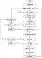
图3为本发明定位方法流程图;Fig. 3 is a flowchart of the positioning method of the present invention;
图4为本发明数据传输的规定格式。Fig. 4 is the prescribed format of data transmission in the present invention.
具体实施方式Detailed ways
本发明结合附图及实施例加以详细说明。The present invention is described in detail with reference to the accompanying drawings and embodiments.
本实施例:GPS模块选用型号为GUGSU36; GPRS模块选用型号为 Q2403A;声波传感器选用型号为Lance LC0107系列振动传感器SN3563配合LC0207恒流源使用;压力传感器选用型号为ROSEMOUNT 3051 GP3A2B21AB4M5D1差压变送器;信号处理单元采用型号为TMS 320F2812;智能高速实时数据采样装置采用申请号为03133458X的发明专利的智能高速实时数据采样装置。In this embodiment: the model of GPS module is GUGSU36; the model of GPRS module is Q2403A; the model of acoustic wave sensor is Lance LC0107 series vibration sensor SN3563 used with LC0207 constant current source; the model of pressure sensor is ROSEMOUNT 3051 GP3A2B21AB4M5D1 differential pressure transmitter; The signal processing unit adopts the model TMS 320F2812; the intelligent high-speed real-time data sampling device adopts the intelligent high-speed real-time data sampling device of the invention patent with the application number 03133458X.
本实施例中管道长为360m,其中从首站上位机起140m处为模拟泄漏位置。沿管道每隔90m加一个声波信号检测下位机,这样,就在距离首末两端90m位置各有一个声波信号检测下位机。In this embodiment, the length of the pipeline is 360m, and the location 140m from the host computer at the first station is the simulated leakage location. Add a sound wave signal detection lower computer every 90m along the pipeline, so that there is a sound wave signal detection lower computer at a distance of 90m from the first and last ends.
本发明,如图1所示,其中声波信号检测下位机包括供电装置、声波传感器、信号调理单元、信号处理单元、GPS模块和GPRS模块;所述的上位机和不间断电源;所述的压力检测下位机为智能高速实时数据采样装置和压力传感器;The present invention, as shown in Figure 1, wherein acoustic wave signal detection lower computer comprises power supply device, acoustic wave sensor, signal conditioning unit, signal processing unit, GPS module and GPRS module; Described host computer and uninterruptible power supply; Described pressure The detection lower computer is an intelligent high-speed real-time data sampling device and a pressure sensor;
该系统的连接:如图2所示,供电装置连接声波传感器供电端、信号调理单元供电端和信号处理单元供电端,为声波传感器、信号调理单元和信号处理单元供电,声波传感器数据输出端连接信号调理单元的输入端DIN1~DIN6,信号调理单元的输出端INA0~INA5连接信号处理单元的输入端ADCINA0~ADCINA5,GPS模块地理和时间数据输出端连接信号处理单元的数据总线端,为定位系统提供准确同步时间信息;信号处理单元SCIRXD和SCITXD输出端分别连接GPRS模块的TXD和RXD输入端,GPRS模块数据传输终端发送管道泄漏信息到工控机,工控机的输出端连接显示器,不间断电源连接工控机、智能高速实时数据采样装置和压力传感器,压力传感器输出端连接智能高速实时数据采样装置的输入端,智能高速实时数据采样装置的输出端连接工控机的输入端。Connection of the system: As shown in Figure 2, the power supply device is connected to the power supply terminal of the acoustic wave sensor, the power supply terminal of the signal conditioning unit and the power supply terminal of the signal processing unit to supply power for the acoustic wave sensor, signal conditioning unit and signal processing unit, and the data output terminal of the acoustic wave sensor is connected to The input terminals DIN1~DIN6 of the signal conditioning unit, the output terminals INA0~INA5 of the signal conditioning unit are connected to the input terminals ADCINA0~ADCINA5 of the signal processing unit, and the geographical and time data output terminals of the GPS module are connected to the data bus terminal of the signal processing unit, which is the positioning system Provide accurate synchronous time information; the output terminals of the signal processing unit SCIRXD and SCITXD are respectively connected to the TXD and RXD input terminals of the GPRS module, the data transmission terminal of the GPRS module sends the pipeline leakage information to the industrial computer, the output terminal of the industrial computer is connected to the display, and the uninterruptible power supply is connected An industrial computer, an intelligent high-speed real-time data sampling device and a pressure sensor, the output end of the pressure sensor is connected to the input end of the intelligent high-speed real-time data sampling device, and the output end of the intelligent high-speed real-time data sampling device is connected to the input end of the industrial computer.
该定位系统的工作过程:压力传感器采集压力信号存入数据库,而声波传感器采集声波信号通过信号调理单元滤波放大处理后进入信号处理单元,经过A/D转换存入RAM,同时打上时间标签。当输油管道在发生泄漏时,会造成局部流体物质损失,引起局部密度减小形成负压波向两端传递,通过检测输油管道两端的负压波产生的下降拐点时间差和负压波传输波速可以确定泄漏的大致位置,也就确定了泄漏到底发生在哪两个声波信号检测下位机之间。此时,就近的上位机的GPRS模块向指定的两个声波信号检测下位机发送接收数据请求,并等待回应;声波信号检测下位机收到控制信号后,启动信号处理单元,停止声波传感器采集数据,并开始从信号处理单元的RAM中依时间倒序逐个取出声波数据作小波去噪处理,然后将处理后的声波数据的幅值与工况设定的警戒值比较,寻找幅值小于警戒值的首个点,该点对应的时刻即认为是声波传感器接收到的由于管道泄漏产生的声音到达时刻。采用这种信号处理方式,简单快速的确定了由于管道泄漏产生的声音到达声波传感器的时刻,避免了采用传统声波定位方式造成的大数据量传输,提高了通讯的效率。此后,将该点对应的时间和幅值信息按照规定的传输格式以总线方式传给无线通讯模块并向上位机发送。无线通讯方式采用基于TCP/IP协议的GPRS通讯方式,并且在发送的数据包中打上时间标签和装置标号。上位机接收到声波信号检测下位机发来的数据包,通过协议转换成时间和幅值数据存入工控机的内存,按照定位算法精确的计算出泄漏点位置在显示器上显示,并再次启动无线通讯单元将定位信息以短信形式向负责人的手机上发送,最后将所有的报警信息及相关数据写入数据库以备查询。The working process of the positioning system: the pressure sensor collects the pressure signal and stores it in the database, while the acoustic wave signal collected by the acoustic wave sensor is filtered and amplified by the signal conditioning unit, then enters the signal processing unit, and is stored in RAM after A/D conversion, and is marked with a time stamp. When the oil pipeline leaks, it will cause the loss of local fluid material, causing the local density to decrease and form negative pressure waves to transmit to both ends. Determining the approximate location of the leak also determines which two acoustic signal detection slaves the leak occurred between. At this time, the GPRS module of the nearby host computer sends and receives data requests to the two specified acoustic wave signal detection lower computers, and waits for a response; after the acoustic wave signal detection lower computer receives the control signal, it starts the signal processing unit and stops the acoustic wave sensor from collecting data , and start to take out the acoustic wave data one by one from the RAM of the signal processing unit in reverse order of time for wavelet denoising processing, then compare the amplitude of the processed acoustic wave data with the warning value set by the working condition, and find the one whose amplitude is smaller than the warning value The first point, the time corresponding to this point is considered to be the arrival time of the sound received by the acoustic wave sensor due to pipeline leakage. Using this signal processing method, it is simple and fast to determine the moment when the sound generated by the pipeline leakage reaches the acoustic wave sensor, avoiding the large amount of data transmission caused by the traditional acoustic wave positioning method, and improving the communication efficiency. After that, the time and amplitude information corresponding to the point is transmitted to the wireless communication module in the form of bus according to the specified transmission format and sent to the upper computer. The wireless communication method adopts the GPRS communication method based on the TCP/IP protocol, and the time stamp and the device label are marked in the sent data packet. The upper computer receives the sound wave signal and detects the data packet sent by the lower computer, converts it into time and amplitude data through the protocol and stores it in the memory of the industrial computer, calculates the location of the leak point accurately according to the positioning algorithm and displays it on the display, and restarts the wireless The communication unit sends the positioning information to the mobile phone of the person in charge in the form of a short message, and finally writes all the alarm information and related data into the database for query.
各个模块的具体功能及实现如下:The specific functions and implementation of each module are as follows:
声波传感器收取外界各种声波信号,要求传感器的灵敏度和采样率足够高,同时耗能要尽量低,安装在输油管道上可收取泄漏点发出的声音,并把声信号转换成电信号。系统中采用的型号为Lance LC0107系列振动传感器SN3563,配合LC0207恒流源使用。The acoustic wave sensor collects various external acoustic signals. The sensitivity and sampling rate of the sensor are required to be high enough, and the energy consumption should be as low as possible. It can be installed on the oil pipeline to collect the sound from the leakage point and convert the acoustic signal into an electrical signal. The model used in the system is Lance LC0107 series vibration sensor SN3563, which is used with LC0207 constant current source.
GPS模块为系统各个组成单元提供准确同步时间信息,系统中选用河南晨星的GPS GUGSU36。The GPS module provides accurate synchronous time information for each component unit of the system, and the GPS GUGSU36 of Henan Morningstar is used in the system.
信号调理单元主要负责把声波传感器输出的电信号进行滤波放大,根据实际的工况和得到的分析数据可推断出泄漏液体摩擦管壁发出的声音频段和信噪比。通过设定滤波频段和放大倍数可有效提高信噪比,滤除大部分噪声。The signal conditioning unit is mainly responsible for filtering and amplifying the electrical signal output by the acoustic wave sensor. According to the actual working conditions and the obtained analysis data, the frequency range and signal-to-noise ratio of the sound emitted by the leaking liquid rubbing against the pipe wall can be deduced. By setting the filter frequency band and magnification, the signal-to-noise ratio can be effectively improved and most noises can be filtered out.
信号处理单元主要是DSP板,信号调理单元输出的模拟信号经过DSP板上自带的A/D转换成数字信号,并存入RAM,同时打上时间标签,这里的RAM起到数据缓存的作用。当无线通讯单元收到上位机发来的控制信号时,DSP利用中断启动对数据的处理,常规状态下,DSP对数据采取只存储不处理的策略。先依时间倒序逐个从RAM取出声波数据作小波去噪处理,再拿处理后的信号幅值与预先由工况设定的警戒值作比较,获得首个幅值小于警戒值的数据,将此数据点对应的时间信息和幅值信息保存起来,这样,就完成了整个信号处理的过程。The signal processing unit is mainly a DSP board. The analog signal output by the signal conditioning unit is converted into a digital signal by the A/D on the DSP board, and stored in RAM, and marked with a time stamp. The RAM here acts as a data cache. When the wireless communication unit receives the control signal from the host computer, the DSP uses an interrupt to start processing the data. Under normal conditions, the DSP adopts a strategy of only storing but not processing the data. First take out the acoustic wave data from the RAM one by one in reverse order of time for wavelet denoising processing, then compare the processed signal amplitude with the warning value set in advance by the working conditions, and obtain the first data whose amplitude is less than the warning value, and then The time information and amplitude information corresponding to the data points are stored, thus completing the entire signal processing process.
GPRS模块 选用Q2403A。与其他的无线通讯方式相比,GPRS技术具有接入范围广,传输速率高,永远在线等优势,为了防止传输延时,丢包以及多个装置向控制台发送产生数据混淆的情况,无线通讯方式基于TCP/IP协议,并且要求传输的数据应按照规定的传输格式打包传输,以确保上位机接收到的数据是唯一标识一个分站信号检测装置的情况。The GPRS module selects Q2403A. Compared with other wireless communication methods, GPRS technology has the advantages of wide access range, high transmission rate, and always online. In order to prevent transmission delay, packet loss, and data confusion caused by multiple devices sending to the console, wireless communication The method is based on the TCP/IP protocol, and the data required to be transmitted should be packaged and transmitted according to the specified transmission format to ensure that the data received by the host computer uniquely identifies a substation signal detection device.
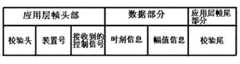
如图4所示,为数据传输的规定格式,校验头和校验尾标识了数据包为指定的由于泄漏产生的声波信息数据包,装置号表示是此条管道上第几个信号检测装置;接收到的控制信号只能选0和1,0表示首站发送控制信号,1表示末站发送控制信号;时间信息和幅值信息为信号处理单元得到的数据点对应的时间信息和幅值信息。As shown in Figure 4, it is the specified format for data transmission. The check header and check tail indicate that the data packet is a specified acoustic wave information data packet due to leakage, and the device number indicates the number of signal detection devices on this pipeline. ;The received control signal can only choose 0 and 1, 0 means that the first station sends a control signal, and 1 means that the last station sends a control signal; the time information and amplitude information are the time information and amplitude corresponding to the data points obtained by the signal processing unit information.
本系统由位于首末两站的上位机和沿管道布置的若干个声波信号检测下位机构成。上位机每隔6小时要对各个声波信号装置进行循环检测,检测的内容包括:判断装置与上位机的通讯情况,如果连接中断或不畅,重新建立连接;判断各个检测装置的时间是否一致,每隔一段时间用GPS对系统进行时间校准。同时,装置本身还具有自检功能,GPRS模块在不发送数据时处于待机状态,以节省电能。只有当声波信号检测下位机收到上位机发来的控制信号时,才会启动数据传输终端发送数据包;当上位机完成数据接收后检测装置的GPRS模块又会自动变成待机状态。This system is composed of the upper computer located at the first and last two stations and several acoustic signal detection lower computers arranged along the pipeline. The host computer should perform cyclic detection on each sound wave signal device every 6 hours. The detection content includes: judging the communication between the device and the host computer, if the connection is interrupted or not smooth, re-establish the connection; judging whether the time of each detection device is consistent, The system is time calibrated with GPS at regular intervals. At the same time, the device itself also has a self-test function, and the GPRS module is in a standby state when not sending data to save power. Only when the sound wave signal detection lower computer receives the control signal from the upper computer, it will start the data transmission terminal to send data packets; when the upper computer completes the data reception, the GPRS module of the detection device will automatically turn into a standby state.
基于负压波和声波协同检测,意味着只有当负压波报警和声波报警同时满足,才认定管道真正泄漏。由理论知道,声波沿管壁的传播速度要远大于负压波在管道内的传播速度,因此,在一般情况下,当出现声波信号到达检测装置的时刻大于站上负压波产生的下降拐点时刻,即发生泄漏首先由负压波拐点检测到,这种情况即是一种异常,这种异常不是泄漏报警。利用这两类时刻还可以区分出工况和泄漏报警。当负压波法检测到管道泄漏时,不仅可以计算出泄漏的大致位置,同时,还可以计算出发生泄漏的大致时刻,如果声波信号到达检测装置的时刻与通过计算得到的发生泄漏的时刻大致接近,就认为是有效的泄漏报警,否则认定是工况。上述理论可以在一定程度上解决系统误报的问题。Based on the coordinated detection of negative pressure waves and sound waves, it means that only when the negative pressure wave alarm and the sound wave alarm are satisfied at the same time, can the pipeline be truly leaked. It is known from the theory that the propagation speed of sound waves along the pipe wall is much greater than the propagation speed of negative pressure waves in the pipe. Therefore, in general, when the sound wave signal reaches the detection device, it is greater than the falling inflection point of the negative pressure wave on the station. Time, that is, the leakage is first detected by the inflection point of the negative pressure wave. This situation is an abnormality, and this abnormality is not a leakage alarm. Using these two types of time can also distinguish between operating conditions and leak alarms. When the pipeline leakage is detected by the negative pressure wave method, not only the approximate location of the leakage can be calculated, but also the approximate time when the leakage occurs. If it is close, it is considered to be an effective leak alarm, otherwise it is considered to be a working condition. The above theory can solve the problem of system false positives to a certain extent.
基于负压波和声波协同检测的管道泄漏定位系统进行定位的方法,按以下步骤进行:如图3所示,The method of locating the pipeline leakage location system based on the cooperative detection of negative pressure waves and acoustic waves is carried out according to the following steps: as shown in Figure 3,
步骤一、当管道发生泄漏,管道首末端的压力传感器检测到压力下降,计算时间差,负压波在水中的传播速度为1051.1m/s,压力信号的采样率为50Hz,检测到的时间差为100ms,通过以上数据粗略计算出泄漏的大致位置,泄漏的大致位置为距离管道首端127m,从而确定泄漏发生在两个声波信号检测下位机之间;
步骤二:就近的上位机通过GPRS模块向泄漏点两侧就近的声波信号检测下位机发送接收声波信号请求,并等待回应;声波信号检测下位机收到控制信号后,信号处理单元开始处理数据并通过GPRS模块向所述的上位机发送处理后的数据;Step 2: The nearby upper computer sends and receives the acoustic signal request to the adjacent acoustic wave signal detection lower computers on both sides of the leakage point through the GPRS module, and waits for a response; after the acoustic wave signal detection lower computer receives the control signal, the signal processing unit starts to process the data and Send the processed data to the host computer through the GPRS module;
步骤三、下位机开始分析数据,并将分析出的信息打包通过GPRS模块发到上位机上,时间差为2.9ms,声波信号检测下位机的采样率为10000Hz;
步骤四:上位机接收到声波信号检测下位机发送过来的数据存入工控机的内存,依据定位方法对泄漏点进行精确定位并在显示器上显示,声波产生的振动沿水管壁的传播速度为5232m/s,通过计算,确定定位位置为140.6m。Step 4: The upper computer receives the sound wave signal and detects the data sent by the lower computer and stores it in the memory of the industrial computer, and accurately locates the leak point according to the positioning method and displays it on the display. The vibration generated by the sound wave propagates along the water pipe wall at a speed of 5232m/s, through calculation, the positioning position is determined to be 140.6m.
Claims (1)
Priority Applications (1)
| Application Number | Priority Date | Filing Date | Title |
|---|---|---|---|
| CN 201010297897CN101968162B (en) | 2010-09-30 | 2010-09-30 | Pipeline leakage positioning system and method based on collaborative detection with negative pressure wave and sound wave |
Applications Claiming Priority (1)
| Application Number | Priority Date | Filing Date | Title |
|---|---|---|---|
| CN 201010297897CN101968162B (en) | 2010-09-30 | 2010-09-30 | Pipeline leakage positioning system and method based on collaborative detection with negative pressure wave and sound wave |
Publications (2)
| Publication Number | Publication Date |
|---|---|
| CN101968162A CN101968162A (en) | 2011-02-09 |
| CN101968162Btrue CN101968162B (en) | 2012-12-19 |
Family
ID=43547359
Family Applications (1)
| Application Number | Title | Priority Date | Filing Date |
|---|---|---|---|
| CN 201010297897Expired - Fee RelatedCN101968162B (en) | 2010-09-30 | 2010-09-30 | Pipeline leakage positioning system and method based on collaborative detection with negative pressure wave and sound wave |
Country Status (1)
| Country | Link |
|---|---|
| CN (1) | CN101968162B (en) |
Families Citing this family (28)
| Publication number | Priority date | Publication date | Assignee | Title |
|---|---|---|---|---|
| CN102242872B (en)* | 2011-06-22 | 2013-01-30 | 东北大学 | Oil pipeline network leak detection method based on generalized fuzzy hyperbolic tangent model |
| CN103062628A (en)* | 2012-11-02 | 2013-04-24 | 常州大学 | Urban gas buried pipeline leakage detection and locating method and applications thereof |
| CN103822097B (en) | 2012-11-16 | 2016-11-16 | 国际商业机器公司 | The method and device of the velocity of wave of suction wave is estimated in fluid-transporting tubing |
| CN104696711A (en)* | 2013-12-09 | 2015-06-10 | 大连天鸣科技有限公司 | Method for rapid and accurate positioning of pipeline leakage point |
| CN103684915B (en)* | 2013-12-16 | 2016-08-17 | 武汉虹信通信技术有限责任公司 | Slave computer Frame exception localization method based on host computer scenario reduction |
| CN104063588B (en)* | 2014-06-12 | 2017-03-22 | 东北大学 | Multi-source data fusion-based method for predicting pipeline corrosion defect size |
| CN104197203B (en)* | 2014-07-14 | 2017-10-17 | 东北大学 | A kind of pipeline leakage positioning method based on fuzzy reasoning |
| CN104595730B (en)* | 2015-01-15 | 2015-08-12 | 中国石油大学(华东) | A kind of oil and gas pipeline leakage localization method based on magnitudes of acoustic waves attenuation model |
| CN104595729B (en)* | 2015-01-15 | 2015-08-12 | 中国石油大学(华东) | A kind of oil and gas pipeline leakage localization method based on magnitudes of acoustic waves |
| CN105972442A (en)* | 2016-05-10 | 2016-09-28 | 肖香福 | Detector for gas pipeline |
| CN106090629A (en)* | 2016-06-15 | 2016-11-09 | 中冶南方工程技术有限公司 | Urban Underground piping lane water supply line leak detection system and method |
| CN107869654B (en)* | 2016-09-27 | 2020-03-10 | 中国石油天然气股份有限公司 | Oil-gas pipeline pipe burst detection positioning method |
| CN107888296A (en)* | 2016-09-30 | 2018-04-06 | 通用电气公司 | Utilize the communication system and method for pipeline configuration |
| CN109798451B (en)* | 2017-11-16 | 2020-09-08 | 中国石油天然气股份有限公司 | Method for determining leakage position of oil gas gathering and transportation pipeline |
| CN107907279B (en)* | 2017-11-20 | 2020-09-22 | 中国石油大学(华东) | Analysis method of multiphase flow pipeline leakage acoustic signal based on wavelet coefficient amplitude |
| CN108488638B (en)* | 2018-03-28 | 2019-08-20 | 东北大学 | Pipeline Leakage Monitoring System and Method Based on Acoustic Negative Pressure Wave Hybrid Monitoring |
| CN108931344A (en)* | 2018-05-08 | 2018-12-04 | 山东潍微科技股份有限公司 | A kind of water supply line leakage loss table end intelligent wireless remote transmission warning device and its implementation |
| CN110196144B (en)* | 2019-06-13 | 2021-10-01 | 中国海洋石油集团有限公司 | Intelligent monitoring system for leakage characteristic data of deep water umbilical cable based on virtual instrument |
| CN111271608A (en)* | 2020-03-05 | 2020-06-12 | 北京中竞国际能源科技有限公司 | Leakage management system and method for compressed air system |
| CN111608650B (en)* | 2020-07-09 | 2020-12-11 | 西安海联石化科技有限公司 | Method for detecting oil well oil pipe and casing pipe defects by using infrasonic waves |
| CN111904477B (en)* | 2020-07-23 | 2022-12-23 | 河北医科大学第二医院 | A gastroesophageal reflux sampling device for general surgery |
| CN112483907B (en)* | 2020-11-10 | 2022-02-11 | 深圳市祥为测控技术有限公司 | Pipeline leakage detection system and method |
| CN112483910A (en)* | 2020-12-04 | 2021-03-12 | 常州大学 | Gas-liquid two-phase flow pipeline leakage simulation device based on sound-pressure coupling |
| CN113090960A (en)* | 2021-04-21 | 2021-07-09 | 北京科技大学 | Filling slurry pipeline leakage monitoring system and method |
| CN113654728B (en)* | 2021-07-16 | 2023-09-01 | 汕头大学 | A method and system for locating the inflection point of negative pressure wave signal based on coordinate transformation |
| CN114017681A (en)* | 2021-11-05 | 2022-02-08 | 福州大学 | Pipeline leak detection and positioning method based on coupling of negative pressure wave and harmonic attenuation method |
| CN114017685A (en)* | 2021-11-26 | 2022-02-08 | 国家石油天然气管网集团有限公司华南分公司 | Method, device and medium for detecting leakage of refined oil pipeline |
| CN114636114A (en)* | 2022-03-30 | 2022-06-17 | 湖南虹桥工业科技股份有限公司 | Pipeline leakage signal detection device |
Citations (4)
| Publication number | Priority date | Publication date | Assignee | Title |
|---|---|---|---|---|
| CN1755342A (en)* | 2004-09-28 | 2006-04-05 | 北京埃德尔黛威新技术有限公司 | Method and apparatus for detecting leakage of liquid pressure pipeline |
| CN101196872A (en)* | 2007-11-19 | 2008-06-11 | 清华大学 | Leak detection and localization method based on pressure and acoustic wave information fusion |
| CN201188051Y (en)* | 2008-01-18 | 2009-01-28 | 北京世纪华扬能源科技有限公司 | Positioning apparatus for detecting acoustic wave leakage |
| CN101625071A (en)* | 2009-08-07 | 2010-01-13 | 天津大学 | Method for measuring and locating leakage of gas pipelines |
- 2010
- 2010-09-30CNCN 201010297897patent/CN101968162B/ennot_activeExpired - Fee Related
Patent Citations (4)
| Publication number | Priority date | Publication date | Assignee | Title |
|---|---|---|---|---|
| CN1755342A (en)* | 2004-09-28 | 2006-04-05 | 北京埃德尔黛威新技术有限公司 | Method and apparatus for detecting leakage of liquid pressure pipeline |
| CN101196872A (en)* | 2007-11-19 | 2008-06-11 | 清华大学 | Leak detection and localization method based on pressure and acoustic wave information fusion |
| CN201188051Y (en)* | 2008-01-18 | 2009-01-28 | 北京世纪华扬能源科技有限公司 | Positioning apparatus for detecting acoustic wave leakage |
| CN101625071A (en)* | 2009-08-07 | 2010-01-13 | 天津大学 | Method for measuring and locating leakage of gas pipelines |
Non-Patent Citations (3)
| Title |
|---|
| 丁梅峰.输油管道泄漏监测的压力和动态压力联合监测方法.《企业导报》.2010,(第5期), |
| 余东亮,张晶,刘梅,胡文兴,李章青,李向辉,王立坤.基于压力波技术的管道泄漏监测系统.《石油机械》.2010,第38卷(第7期),* |
| 输油管道泄漏监测的压力和动态压力联合监测方法;丁梅峰;《企业导报》;20100531(第5期);297* |
Also Published As
| Publication number | Publication date |
|---|---|
| CN101968162A (en) | 2011-02-09 |
Similar Documents
| Publication | Publication Date | Title |
|---|---|---|
| CN101968162B (en) | Pipeline leakage positioning system and method based on collaborative detection with negative pressure wave and sound wave | |
| CN106352243B (en) | A Gas Pipeline Leak Detection System Based on Acoustic Wave Method | |
| CN201273457Y (en) | A pipeline leakage monitoring device | |
| CN1246672C (en) | Method and device for intelligent diagnosis and location of leakage fault of fluid delivery pipeline | |
| CN106090629A (en) | Urban Underground piping lane water supply line leak detection system and method | |
| CN101684894B (en) | Pipeline leakage monitoring method and device | |
| CN205090197U (en) | Leak detection system and monitoring facilities of pipeline | |
| CN111271610B (en) | Liquid pipeline leakage detection early warning device and method | |
| CN102644851B (en) | Natural gas dry gas pipeline intelligent detection ball | |
| CN202074237U (en) | Pipeline leakage monitoring and negative pressure protecting device | |
| CN106369288B (en) | Water supply network leakage loss monitoring system | |
| CN103216732B (en) | Real-time monitoring and positioning system for water leakage of pipe network | |
| CN103245454A (en) | Non-intrusive pipeline real-time monitoring, prewarning and fault locating system | |
| CN103629534B (en) | Oil pipeline leakage detection and positioning method based on comprehensive signals | |
| CN203477909U (en) | Pipeline leakage automatic monitoring positioning device based on low-frequency sound waves and negative-pressure waves | |
| CN108758354A (en) | Heat supply pipeline leak detection system and method based on infrasound and reference point | |
| CN106289121B (en) | A kind of computational methods of the equivalent pipe range of reducer pipe | |
| KR101656858B1 (en) | Acoustic Emission sensor apparatus and wireless defect diagnostics system for high pressure pipe using thereof | |
| CN107701927B (en) | Leakage point detection system and method inside water pipe are realized using sound source generator | |
| CN207316488U (en) | A kind of long distance wireless routine for pipe-line transportation system leakage or gas leakage | |
| CN110185940A (en) | A kind of monitoring of fuel gas pipeline leakage and positioning system | |
| KR101654791B1 (en) | acoustics and vibration complex sensing unit for defect of plant and defect diagnostics system for high pressure pipe | |
| CN206207017U (en) | The early warning and monitoring device that a kind of ore slurry pipeline is blocked or leaked | |
| CN103604570A (en) | Supersonic wave airtight detection method and supersonic wave airtight detection device | |
| CN202580643U (en) | Safety online management system for pipelines |
Legal Events
| Date | Code | Title | Description |
|---|---|---|---|
| C06 | Publication | ||
| PB01 | Publication | ||
| C10 | Entry into substantive examination | ||
| SE01 | Entry into force of request for substantive examination | ||
| C14 | Grant of patent or utility model | ||
| GR01 | Patent grant | ||
| CF01 | Termination of patent right due to non-payment of annual fee | Granted publication date:20121219 Termination date:20140930 | |
| EXPY | Termination of patent right or utility model |