CN101963846A - Optical pen - Google Patents
Optical penDownload PDFInfo
- Publication number
- CN101963846A CN101963846ACN201010240794.0ACN201010240794ACN101963846ACN 101963846 ACN101963846 ACN 101963846ACN 201010240794 ACN201010240794 ACN 201010240794ACN 101963846 ACN101963846 ACN 101963846A
- Authority
- CN
- China
- Prior art keywords
- tip
- optical pen
- switch
- optical
- pen according
- Prior art date
- Legal status (The legal status is an assumption and is not a legal conclusion. Google has not performed a legal analysis and makes no representation as to the accuracy of the status listed.)
- Granted
Links
Images


Classifications
- G—PHYSICS
- G06—COMPUTING OR CALCULATING; COUNTING
- G06F—ELECTRIC DIGITAL DATA PROCESSING
- G06F3/00—Input arrangements for transferring data to be processed into a form capable of being handled by the computer; Output arrangements for transferring data from processing unit to output unit, e.g. interface arrangements
- G06F3/01—Input arrangements or combined input and output arrangements for interaction between user and computer
- G06F3/03—Arrangements for converting the position or the displacement of a member into a coded form
- G06F3/033—Pointing devices displaced or positioned by the user, e.g. mice, trackballs, pens or joysticks; Accessories therefor
- G06F3/0354—Pointing devices displaced or positioned by the user, e.g. mice, trackballs, pens or joysticks; Accessories therefor with detection of 2D relative movements between the device, or an operating part thereof, and a plane or surface, e.g. 2D mice, trackballs, pens or pucks
- G06F3/03545—Pens or stylus
Landscapes
- Engineering & Computer Science (AREA)
- General Engineering & Computer Science (AREA)
- Theoretical Computer Science (AREA)
- Human Computer Interaction (AREA)
- Physics & Mathematics (AREA)
- General Physics & Mathematics (AREA)
- Position Input By Displaying (AREA)
Abstract
Translated fromChinese
Description
Translated fromChinese相关申请的交叉引用Cross References to Related Applications
本申请要求2009年7月24日提交的美国临时申请61/228,488的优先权权益,其全部内容通过引用合并于此。This application claims the benefit of priority to US Provisional Application 61/228,488, filed July 24, 2009, the entire contents of which are hereby incorporated by reference.
背景技术Background technique
本申请涉及光学笔,更具体地,涉及提供触觉书写体验的光学笔。This application relates to optical pens, and more particularly, to optical pens that provide a tactile writing experience.
在各种环境中可能使用图像显示装置。例如,诸如投影仪、电视、监视器等的图像显示装置可以适用于显示包括文本、图形、视频图像、静止图像、演示等的图像。可以在教育环境、商业设施、会议室、会议设施等中发现这些图像显示装置。The image display device may be used in various environments. For example, an image display device such as a projector, television, monitor, etc. may be adapted to display images including text, graphics, video images, still images, presentations, and the like. These image display devices can be found in educational environments, commercial facilities, conference rooms, meeting facilities, and the like.
可以在诸如教育场所(例如教室)、商业设施、会议室等的各种环境中使用图像显示装置。在诸如投影仪的图像显示装置的情况下,例如,通过图像显示装置将图像投影到可被一个或更多个观众成员观看的观看表面上来允许大幅面观看。利用这种图像显示装置进行演示的演示者需要能够在进行演示时对在观看表面上显示的文本和/或图像进行注释。因此,可以将输入装置配置为与该图像显示装置进行交互,以允许这种实时注释。例如,可以使用光学笔在观看表面上虚拟地进行“书写”,而该图像显示装置可以作为响应地在图像上显示“笔迹”。这样,可以将图像显示装置和观看表面可以共同用作电子白板,其中光学笔用作电子白板笔。The image display device can be used in various environments such as educational places (for example, classrooms), commercial facilities, meeting rooms, and the like. In the case of an image display device such as a projector, for example, large format viewing is enabled by the image display device projecting the image onto a viewing surface viewable by one or more audience members. A presenter making a presentation using such an image display device needs to be able to annotate text and/or images displayed on the viewing surface while making the presentation. Accordingly, an input device may be configured to interact with the image display device to allow such real-time annotation. For example, an optical pen can be used to virtually "write" on the viewing surface, and the image display device can display the "handwriting" on the image in response. In this way, the image display device and the viewing surface can be used together as an electronic whiteboard, wherein the optical pen is used as an electronic whiteboard marker.
因为用户没有实际的表面以在其上进行书写,因此与传统的书写设备相比,利用这种光学笔进行书写、绘制等将更有挑战性。例如,当利用光学笔在空气中进行“书写”时,难以对笔划进行控制、对笔法和笔迹进行控制、保持对光学笔的先前位置的跟踪等。Writing, drawing, etc. with such an optical pen can be more challenging than with conventional writing devices because the user has no actual surface to write on. For example, when "writing" in the air with an optical pen, it is difficult to control strokes, control strokes and handwriting, keep track of the previous position of the optical pen, etc.
发明内容Contents of the invention
这里公开了与用于光学笔的尖端相关的各种实施例。一个公开的实施例包括一种用于光学笔的尖端,其中该尖端位于该光学笔上,以使得不阻挡朝向该光学笔的输入光,并且其中,在该尖端接触观看表面时,该尖端向用户提供触觉反馈。Various embodiments are disclosed herein related to a tip for an optical pen. One disclosed embodiment includes a tip for an optical pen, wherein the tip is positioned on the optical pen so as not to block input light towards the optical pen, and wherein, when the tip contacts a viewing surface, the tip The user provides haptic feedback.
本发明的一个实施例提供了一种光学笔。光学笔可以包括具有末端的细长的壳体。光学传感器可以位于壳体中,光学传感器被配置为通过在壳体的末端处的末端开口来接收来自观看表面的输入光。尖端可以从壳体的末端延伸,尖端可以被定位在末端开口附近。尖端可以被定位为当尖端的最末端部分与观看表面相接触时不阻挡至光学笔的输入光。One embodiment of the present invention provides an optical pen. The optical pen may include an elongated housing having a distal end. An optical sensor may be located in the housing, the optical sensor being configured to receive input light from the viewing surface through an end opening at an end of the housing. A tip can extend from the end of the housing, and the tip can be positioned near the end opening. The tip may be positioned so as not to block input light to the optical pen when the endmost portion of the tip is in contact with the viewing surface.
在光学笔的一个方面,在尖端接触观看表面时,尖端的最末端部分可以向用户提供触觉反馈。In one aspect of the optical pen, the endmost portion of the tip can provide tactile feedback to the user when the tip contacts the viewing surface.
在光学笔的另一个方面,尖端可以包括细长部件,尖端的最末端部分包括球形表面。In another aspect of the optical pen, the tip may include an elongated member, the endmost portion of the tip including a spherical surface.
在光学笔的另一个方面,与细长部件相比,尖端的最末端部分可以具有更大的截面面积。In another aspect of the optical pen, the endmost portion of the tip may have a larger cross-sectional area than the elongated member.
在光学笔的另一个方面,尖端可以包括具有朝向尖端的最末端部分减小的截面面积的楔形。In another aspect of the optical pen, the tip may include a wedge shape with a decreasing cross-sectional area toward an endmost portion of the tip.
在光学笔的另一个方面,尖端可以包括通过与观看表面相接合来驱动的开关。In another aspect of the optical pen, the tip can include a switch that is actuated by engagement with the viewing surface.
在光学笔的另一个方面,开关可以是按钮开关、推/拉开关、摇臂开关、旋转开关、拨动开关或可滑动开关。In another aspect of the optical pen, the switch can be a push button switch, a push/pull switch, a rocker switch, a rotary switch, a toggle switch, or a slideable switch.
在光学笔的另一个方面,开关可以被集成到尖端中,并且由尖端的按钮驱动。In another aspect of the optical pen, a switch can be integrated into the tip and actuated by a button on the tip.
在光学笔的另一个方面,开关可以是通过对着观看表面按下尖端来驱动的可按下按钮。In another aspect of the optical pen, the switch can be a depressible button actuated by pressing the tip against the viewing surface.
在光学笔的另一个方面,光学传感器可以是光检测器。In another aspect of the optical pen, the optical sensor can be a light detector.
在光学笔的另一个方面,透镜可以被附着到壳体,并且被定位以使输入光聚焦到光检测器上。In another aspect of the optical pen, a lens can be attached to the housing and positioned to focus input light onto the light detector.
在光学笔的另一个方面,无线发送器可以位于壳体中,并且被电连接到光学传感器。In another aspect of the optical pen, a wireless transmitter can be located in the housing and electrically connected to the optical sensor.
本发明的另一个实施例提供了一种显示系统。该显示系统可以包括图像显示装置,该图像显示装置包括用于投影图像的图像生成装置。图像显示装置的处理器可以被配置为接收来自输入装置的光信号数据,并且计算表示图像上的输入装置正指向之处的位置数据。计算系统可以被配置为从图像显示装置接收位置数据,并且将图像数据发送到图像显示装置。图像数据可以基于位置数据。显示系统可以包括光学笔装置,光学笔装置包括具有末端的细长的壳体。光学传感器可以位于壳体中,并被配置为通过在壳体的末端处的末端开口来接收来自观看表面的输入光。无线发送器可以位于壳体中,并被电连接到光学传感器。无线发送器可以被配置为与图像显示装置进行无线通信。尖端可以从壳体的末端延伸,尖端可以被定位在末端开口附近。尖端可以被定位为当尖端的最末端部分与观看表面相接触时不阻挡至光学笔的输入光。Another embodiment of the present invention provides a display system. The display system may include an image display device including image generating means for projecting an image. The processor of the image display device may be configured to receive the light signal data from the input device and calculate positional data representing where on the image the input device is being pointed. The computing system can be configured to receive the location data from the image display device, and to send the image data to the image display device. Image data may be based on location data. The display system may include an optical pen device including an elongated housing having a distal end. An optical sensor may be located in the housing and configured to receive input light from the viewing surface through an end opening at an end of the housing. A wireless transmitter can be located in the housing and electrically connected to the optical sensor. The wireless transmitter may be configured to communicate wirelessly with the image display device. A tip can extend from the end of the housing, and the tip can be positioned near the end opening. The tip may be positioned so as not to block input light to the optical pen when the endmost portion of the tip is in contact with the viewing surface.
在显示系统的一个方面,尖端可以包括通过与观看表面相接合来驱动的开关。In one aspect of the display system, the tip can include a switch that is actuated by engaging the viewing surface.
在显示系统的另一个方面,开关的驱动可以使得将激活信号从无线发送器发送到图像显示装置。In another aspect of the display system, actuation of the switch may cause an activation signal to be transmitted from the wireless transmitter to the image display device.
在显示系统的另一个方面,激活信号可以包括发送到计算系统的左鼠标按钮信号。In another aspect of the display system, the activation signal can include a left mouse button signal sent to the computing system.
在显示系统的另一个方面,激活信号可以调用由图像显示装置显示的来自计算系统的可选选项的上下文菜单。In another aspect of the display system, the activation signal may invoke a context menu of selectable options from the computing system displayed by the image display device.
在显示系统的另一个方面,尖端可以包括细长部件,尖端的最末端部分可以包括球形表面。In another aspect of the display system, the tip can comprise an elongated member and the endmost portion of the tip can comprise a spherical surface.
在显示系统的另一个方面,与细长部件相比,尖端的最末端部分可以具有更大的截面面积。In another aspect of the display system, the distal-most portion of the tip can have a larger cross-sectional area than the elongated member.
在显示系统的另一个方面,尖端可以包括具有朝向尖端的最末端部分减小的截面面积的楔形。In another aspect of the display system, the tip can include a wedge shape with a decreasing cross-sectional area toward an endmost portion of the tip.
附图说明Description of drawings
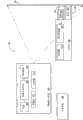
图1示出了图像显示系统的实施例的框图。Fig. 1 shows a block diagram of an embodiment of an image display system.
图2示出了图像显示系统的实施例的示意图。Fig. 2 shows a schematic diagram of an embodiment of an image display system.
图3示出了包括尖端的实施例的示例光学笔的示意图。Figure 3 shows a schematic diagram of an example optical pen including an embodiment of a tip.
图4示出了包括尖端的实施例的另一示例光学笔的示意图。Figure 4 shows a schematic diagram of another example optical pen including an embodiment of a tip.
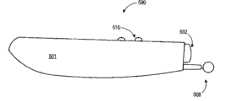
图5示出了包括尖端的实施例的又一示例光学笔的示意图。Figure 5 shows a schematic diagram of yet another example optical pen including an embodiment of a tip.
具体实施方式Detailed ways
如这里所公开的,可以使用光学笔在观看表面上虚拟地进行“书写”,而图像显示装置可以作为响应地在图像上显示“笔迹”。这样,图像显示装置和观看表面可以共同用作电子白板,其中光学笔用作电子白板笔。以与书写、绘制和其它这种精确操控相一致的方式控制这种光学笔是有挑战性的。这些问题可以通过这里公开的在使用光学笔时提供触觉书写体验的用于光学笔的尖端的实施例来解决。能够理解,这里描述的示例是非限定性的,并且被提供以帮助示出用于光学笔的尖端的各种实施例。As disclosed herein, an optical pen can be used to virtually "write" on a viewing surface, and the image display device can responsively display the "writing" on the image. In this way, the image display device and viewing surface can be used together as an electronic whiteboard, with the optical pen used as an electronic whiteboard marker. Controlling such optical pens in a manner consistent with writing, drawing, and other such precise manipulations is challenging. These problems can be addressed by embodiments of the tip for an optical pen disclosed herein that provide a tactile writing experience when using the optical pen. It can be appreciated that the examples described herein are non-limiting and are provided to help illustrate various embodiments for a tip for an optical pen.
图1示出了图像显示系统100的实施例。图像显示系统100可以包括被配置为将图像投影到观看表面104上的图像显示装置102。例如,图像显示系统100可以是被配置为用于以大显示幅面显示图像以用于进行组观看的系统。如这里描述并示出的,图像显示装置可以是诸如正投影装置之类的投影装置。然而,应当理解,图像显示装置可以是另一类型的显示装置,包括但不限于正投影系统、背投影系统等。在其它实施例中,显示装置可以是LCD系统、激光系统、大幅面显示装置等。作为示例,图像显示装置102可以是投影仪。因此,图像显示装置102可以使用诸如数字光处理之类的任何合适的技术以在观看表面104上显示图像。FIG. 1 shows an embodiment of an
图像显示装置102可以包括被配置用于将光导向图像生成装置108的光源106。在一些实施例中,光源106可以包括位于反射器内的灯,该反射器可以被配置为沿着系统的光路引导大部分的发射光。光源106可以包括任何合适的类型的灯或者光源,包括但不限于金属卤素灯和超高压(UHP)弧光灯、激光、发光二极管(LED)、有机发光二极管等。光源160还可以包括一个或更多个诸如红外线(IR)滤光器或者紫外线(UV)滤光器之类的滤光器,以滤除灯的发射光谱中的不想要的部分。Image display device 102 may include a
如上所述,图像生成装置108可以配置用于接收来自光源106的光,并作为响应地生成图像。图像生成装置可以包括光学引擎、图像产生元件、滤光器、色轮、透镜、反射镜、积分器(integrator)、聚光器和其它合适的光学元件。这种元件可以被配置用来生成图像。例如,图像生成装置可以包括例如但不限于数字微镜(DMD)、LCD面板或者任何其它合适的图像源的图像产生元件。在一些实施例中,图像产生元件可以被配置用于向可依次被配置用于向观看表面投影光的一个或更多个透镜、反射镜或者其它光学元件投影光。在一些实施例中,投影透镜110可以被配置为在观看表面104上显示图像。观看表面的非限定性示例可以包括屏幕、墙等。As noted above, the
图像显示装置102还可以包括存储器112。存储器112可以被可操作地耦合到处理器114,使得处理器114可以执行存储在存储器112上的指令。图像显示装置102可以被配置为从诸如光学笔116之类的输入装置接收数据。The image display device 102 may also include a memory 112 . Memory 112 may be operatively coupled to
光学笔116可以包括用于向图像显示装置102发送数据的发送器118。作为非限定性示例,发送器118可以是射频发送器。光学笔116还可以包括用于接收从观看表面104反射回的在观看表面104上显示的图像的光(即,反射图像光)的光学传感器120。作为反射图像光的示例,图1示出了光输入122。作为非限定性示例,被配置为接收光输入122的光学传感器120可以是光检测器。反射图像光可以在被光学传感器120接收到之前首先进入并经过透镜124。应当理解,光学笔116是光学笔的非限定性示例,可以使用其它这种光学笔作为在图像显示系统100中的输入装置。The optical pen 116 may include a
在一些实施例中,图像显示装置102还可以被配置用于在图像内嵌入图案。相应地,光学笔116还可以被配置为在经由光学传感器120接收反射图像光时读取这些图案作为亮度级(1ight level),以得出光信号数据。然后,光学笔116还可以被配置为例如作为无线发送或者有线发送而将光信号数据发送到图像显示装置102。图像显示装置102还可以被配置为通过一系列图案来计算光学笔116在被投影到观看表面104上的图像中的位置。在计算位置(即,投影的图像中的光学笔正指向之处)时,图像显示装置102还可以被配置用于将位置数据发送到诸如计算系统126之类的计算系统。In some embodiments, image display device 102 may also be configured to embed patterns within images. Correspondingly, the optical pen 116 can also be configured to read these patterns as light levels when receiving reflected image light via the
作为非限定性示例,可以将位置数据作为鼠标坐标发送到计算系统。响应于此,计算系统126可以与图像显示装置102进行交互,以显示在该位置处的图像数据。因此,光学笔116可以用来进行书写、绘制等,以使用图像显示系统100作为电子白板。应当理解,图像显示系统100是图像显示系统的非限定性示例,图像显示系统的其它实施例可以包括被配置用于以另一合适的方式与图像显示装置102进行交互的光学笔116。As a non-limiting example, location data may be sent to the computing system as mouse coordinates. In response thereto, computing system 126 may interact with image display device 102 to display the image data at the location. Therefore, the optical pen 116 can be used for writing, drawing, etc. to use the
光学笔116还可以被配置为具有从光学笔的前部末端伸出的支撑并突出的尖端,例如突出尖端128。突出尖端128可以被适配为与观看表面104相接触或相接合,以模仿在使用诸如传统的白板标记器之类的传统书写设备时所感到的表面接触和触觉反馈。这样,突出尖端128可以通过向用户提供控制和反馈来改善使用光学笔116创建的笔迹。此外,可以将突出尖端128定位在光学笔116的前端处,以不阻挡来自光输入122的光。如所示出的,当突出尖端128与观看表面相接触时,突出尖端128不阻挡光输入122。这是利用突出尖端128相对于观看表面104的接近于横切的布置而示出的。然而,突出尖端128可以在结构上被配置为当被以例如0至45度的相对于观看表面104的典型书写角度放置时不阻挡光输入光122。在一些实施例中,突出尖端128由相对透明的材料构成,和/或包括一个或更多个开口,以使得光输入光122能够通过突出尖端128。Optical pen 116 may also be configured to have a supported and protruding tip, such as protruding
在一些实施例中,突出尖端128还可以包括与可被计算系统解释的辅助选项相对应的开关130。光学笔116可以被配置为经由开关130的用户驱动向图像显示装置发送激活信号。激活信号最终被发送到计算系统126,以指示诸如鼠标点击、书写命令或者绘制命令之类的用户命令。可以由发送器118连同位置数据一起发送激活信号。在一些实施例中,开关130可以经由激活信号调用计算系统126和/或图像显示装置102的用户界面中的上下文菜单,该上下文菜单包含针对光学笔位于其上的接口元件而专门定制的选项。作为示例,当使用光学笔作为鼠标时,开关130可以作为左鼠标按钮来动作。In some embodiments, protruding
此外,开关130可以被配置为以任意合适的方式驱动。作为非限定性示例,开关130可以是按钮开关、推/拉开关、摇臂开关、旋转开关、拨动开关、可滑动开关、可按下开关等。作为示例,开关130可以被集成到突出尖端128中,并由突出尖端128上的按钮驱动。作为另一示例,开关130可以是通过按下突出尖端128来驱动的可按下按钮。Furthermore, switch 130 may be configured to be actuated in any suitable manner. By way of non-limiting example, switch 130 may be a push button switch, a push/pull switch, a rocker switch, a rotary switch, a toggle switch, a slideable switch, a depressible switch, or the like. As an example, switch 130 may be integrated into protruding
图2示出了被配置用于将图像202投影到观看表面204上的图像显示装置,即,投影仪200。然后,光学笔206可以被配置为与投影仪200进行交互,以如在208处所示地对图像202进行注释。FIG. 2 shows an image display device, ie,
图3示出了具有细长(el0ngated)壳体301的光学笔300的实施例的示意图。作为示例,光学笔300可以包括用于接收从图像正被投影在其处的观看表面反射的输入光304的附着到壳体301的透镜302。在接收到输入光304时,透镜302可以将光导向诸如光检测器306之类的光学传感器。光学笔300还可以具有突出尖端308,该突出尖端308被配置为与观看表面相接触,以在与观看表面相接触时得到对光学笔300的用户的触觉反馈,从而模仿传统书写设备的触觉反馈。FIG. 3 shows a schematic view of an embodiment of an
突出尖端308可以被定位在透镜302附近,以使得不阻挡输入光304。在一些实施例中,突出尖端308可以包括开关,其中开关的驱动表示可由图像显示装置和/或计算系统解释的控制。光学笔300还可以包括按钮310,其中按钮310中的每个按钮可以与可被图像显示装置和/或计算系统解释的控制相关联,使得对该按钮的驱动经由各个激活信号将控制传送到该图像显示装置和/或计算系统。例如,按钮310可以是鼠标按钮。在一些实施例中,突出尖端308可以包括用于访问辅助选项的开关。例如,开关可以被配置为左鼠标按钮。此外,在一些实施例中,光学笔300可以是由电池装置312供电的电池操作装置。应当理解,光学笔300是光学笔的一个实施例,并且具有被适配为向用户提供触觉反馈的突出尖端的光学笔的其它实施例在本公开的范围之内。
图4示出了具有细长壳体401的光学笔400的另一实施例的示意图。所示出的壳体401是弯曲的,以提供舒适的握持区域。光学笔400可以包括用于接收从图像正被投影在其处的观看表面反射的输入的透镜402。透镜402可以将光导向光学传感器406。光学笔400还可以具有突出尖端408,该突出尖端408被配置为与观看表面相接触,以向光学笔400的用户提供模仿传统书写设备的触觉反馈的触觉反馈。突出尖端408可以被定位在透镜402附近,以使得不阻挡输入光。FIG. 4 shows a schematic view of another embodiment of an
如所示出的,突出尖端408具有向最末端部分逐渐减小的楔形截面区域。该楔形截面区域还沿着远离透镜402的方向减小。该楔形截面区域的非对称向下偏斜有助于防止突出尖端阻挡至透镜402的输入光。在一些实施例中,突出尖端408可以包括用于访问诸如与左鼠标按钮相对应的辅助选项之类的辅助选项的开关。此外,在一些实施例中,光学笔400可以是由电池装置412供电的电池操作装置。As shown, the protruding
图5示出了具有细长壳体501的光学笔500的另一实施例的示意图。所示出的壳体501是弯曲的,以提供舒适的握持区域。光学笔500可以包括用于接收从图像正被投影在其处的观看表面反射的输入的透镜502。光学笔500还可以具有突出尖端508,该突出尖端508被配置为与观看表面相接触,以得到模仿传统书写设备的触觉反馈的对光学笔500的用户的触觉反馈。突出尖端508可以被定位在透镜502附近,以使得不阻挡输入光。FIG. 5 shows a schematic view of another embodiment of an
如所示出的,突出尖端508具有耦合到具有球形表面的最末端部分的细长部件。最末端部分可以具有大于细长部件的截面面积的截面面积。光学笔500还可以包括按钮510,按钮510与可被图像显示装置和/或计算系统解释的控制相关联,使得该按钮的驱动经由各个激活信号将控制传送到该图像显示装置和/或计算系统。例如,按钮510可以被配置为鼠标按钮。在一些实施例中,突出尖端508可以包括用于访问诸如与左鼠标按钮相对应的辅助选项之类的辅助选项的开关。As shown, the protruding
相信上面描述的公开覆盖了具有独立用途的多个不同的发明。虽然以优选的形式公开了这些发明中的每一个,但是由于可以进行多种变化,因此不认为这里公开并示出的其具体实施例是限定性意图的。本发明的主题包括这里公开的各种要素、特征、功能和/或属性的所有新颖的且非显而易见的组合和子组合。It is believed that the disclosure described above covers a plurality of different inventions with independent utility. While each of these inventions has been disclosed in a preferred form, the specific embodiments thereof disclosed and shown herein are not to be considered limiting, as many changes may be made. The subject matter of the inventions includes all novel and nonobvious combinations and subcombinations of the various elements, features, functions and/or properties disclosed herein.
可以在相关申请中要求保护特征、功能、元素和/或属性的各种组合和子组合所实施的发明。无论这些权利要求针对不同的发明还是针对相同的发明,无论相对于任何原始权利要求而言在范围上不同、更宽、更窄还是相同,这种权利要求也都被视为被包括在本公开的发明的主题之内。Inventions embodied in various combinations and subcombinations of features, functions, elements, and/or properties may be claimed in related applications. Such claims are also deemed to be included in this disclosure, regardless of whether these claims are directed to a different invention or to the same invention, and whether they are different, wider, narrower, or identical in scope to any original claim. within the subject matter of the invention.
Claims (20)
Applications Claiming Priority (2)
| Application Number | Priority Date | Filing Date | Title |
|---|---|---|---|
| US22848809P | 2009-07-24 | 2009-07-24 | |
| US61/228,488 | 2009-07-24 |
Publications (2)
| Publication Number | Publication Date |
|---|---|
| CN101963846Atrue CN101963846A (en) | 2011-02-02 |
| CN101963846B CN101963846B (en) | 2013-04-24 |
Family
ID=43516743
Family Applications (1)
| Application Number | Title | Priority Date | Filing Date |
|---|---|---|---|
| CN201010240794.0AActiveCN101963846B (en) | 2009-07-24 | 2010-07-23 | Optical pen |
Country Status (2)
| Country | Link |
|---|---|
| US (1) | US20110148824A1 (en) |
| CN (1) | CN101963846B (en) |
Cited By (6)
| Publication number | Priority date | Publication date | Assignee | Title |
|---|---|---|---|---|
| CN102385446A (en)* | 2011-11-14 | 2012-03-21 | 苏州佳世达光电有限公司 | Optical pen |
| CN102722273A (en)* | 2012-05-29 | 2012-10-10 | 苏州瀚瑞微电子有限公司 | Wireless touch pen |
| CN102789325A (en)* | 2011-05-20 | 2012-11-21 | 索尼公司 | Stylus based haptic peripheral for touch screen and tablet devices |
| CN102855003A (en)* | 2011-05-20 | 2013-01-02 | 索尼公司 | Haptic device for position detection |
| CN103576914A (en)* | 2012-07-18 | 2014-02-12 | 宏达国际电子股份有限公司 | System and method for providing stylus tactility |
| CN105103076A (en)* | 2013-04-04 | 2015-11-25 | Lg电子株式会社 | Portable device and controlling method therefor |
Families Citing this family (4)
| Publication number | Priority date | Publication date | Assignee | Title |
|---|---|---|---|---|
| CN103576903B (en)* | 2012-07-24 | 2017-11-24 | 联想(北京)有限公司 | A kind of writing pencil of information processing method and application this method |
| CN103853353A (en)* | 2012-12-06 | 2014-06-11 | 鸿富锦精密工业(深圳)有限公司 | Image projection system |
| WO2016034026A1 (en)* | 2014-09-02 | 2016-03-10 | Spring Power Holdings Limited | A human-computer interface device and system |
| US11614825B2 (en)* | 2021-04-20 | 2023-03-28 | Microsoft Technology Licensing, Llc | Touch status indication for active stylus |
Citations (4)
| Publication number | Priority date | Publication date | Assignee | Title |
|---|---|---|---|---|
| WO2005033923A1 (en)* | 2003-10-07 | 2005-04-14 | Penz Co., Ltd. | A pen-type mouse apparatus |
| US20060078866A1 (en)* | 2004-03-17 | 2006-04-13 | James Marggraff | System and method for identifying termination of data entry |
| CN101154136A (en)* | 2006-09-29 | 2008-04-02 | 联想(北京)有限公司 | Mouse pen and its implementing method |
| CN101315587A (en)* | 2008-07-08 | 2008-12-03 | 圆展科技股份有限公司 | cursor control device |
Family Cites Families (12)
| Publication number | Priority date | Publication date | Assignee | Title |
|---|---|---|---|---|
| US4808980A (en)* | 1987-10-22 | 1989-02-28 | Wang Laboratories, Inc. | Electronic light pointer for a projection monitor |
| US5113041A (en)* | 1990-12-28 | 1992-05-12 | At&T Bell Laboratories | Information processing |
| US5502514A (en)* | 1995-06-07 | 1996-03-26 | Nview Corporation | Stylus position sensing and digital camera with a digital micromirror device |
| US6377249B1 (en)* | 1997-11-12 | 2002-04-23 | Excel Tech | Electronic light pen system |
| US6111565A (en)* | 1998-05-14 | 2000-08-29 | Virtual Ink Corp. | Stylus for use with transcription system |
| US20060028456A1 (en)* | 2002-10-10 | 2006-02-09 | Byung-Geun Kang | Pen-shaped optical mouse |
| US7502507B2 (en)* | 2002-10-31 | 2009-03-10 | Microsoft Corporation | Active embedded interaction code |
| US20040217941A1 (en)* | 2003-04-30 | 2004-11-04 | Shoei-Lai Chen | Hand-held wireless computer cursor controlling device |
| US7421111B2 (en)* | 2003-11-07 | 2008-09-02 | Mitsubishi Electric Research Laboratories, Inc. | Light pen system for pixel-based displays |
| TWI234733B (en)* | 2003-11-17 | 2005-06-21 | Primax Electronics Ltd | Cursor control device |
| US7403658B2 (en)* | 2005-04-15 | 2008-07-22 | Microsoft Corporation | Direct homography computation by local linearization |
| GB2431032A (en)* | 2005-10-05 | 2007-04-11 | Hewlett Packard Development Co | Data encoding pattern comprising markings composed of coloured sub-markings |
- 2010
- 2010-07-23USUS12/842,889patent/US20110148824A1/ennot_activeAbandoned
- 2010-07-23CNCN201010240794.0Apatent/CN101963846B/enactiveActive
Patent Citations (4)
| Publication number | Priority date | Publication date | Assignee | Title |
|---|---|---|---|---|
| WO2005033923A1 (en)* | 2003-10-07 | 2005-04-14 | Penz Co., Ltd. | A pen-type mouse apparatus |
| US20060078866A1 (en)* | 2004-03-17 | 2006-04-13 | James Marggraff | System and method for identifying termination of data entry |
| CN101154136A (en)* | 2006-09-29 | 2008-04-02 | 联想(北京)有限公司 | Mouse pen and its implementing method |
| CN101315587A (en)* | 2008-07-08 | 2008-12-03 | 圆展科技股份有限公司 | cursor control device |
Cited By (9)
| Publication number | Priority date | Publication date | Assignee | Title |
|---|---|---|---|---|
| CN102789325A (en)* | 2011-05-20 | 2012-11-21 | 索尼公司 | Stylus based haptic peripheral for touch screen and tablet devices |
| CN102855003A (en)* | 2011-05-20 | 2013-01-02 | 索尼公司 | Haptic device for position detection |
| CN102855003B (en)* | 2011-05-20 | 2015-08-26 | 索尼公司 | For the haptic apparatus that position is detected |
| CN102789325B (en)* | 2011-05-20 | 2016-03-16 | 索尼公司 | For hand-written pen type sense of touch utility appliance and the tablet devices of touch-screen |
| CN102385446A (en)* | 2011-11-14 | 2012-03-21 | 苏州佳世达光电有限公司 | Optical pen |
| CN102722273A (en)* | 2012-05-29 | 2012-10-10 | 苏州瀚瑞微电子有限公司 | Wireless touch pen |
| CN103576914A (en)* | 2012-07-18 | 2014-02-12 | 宏达国际电子股份有限公司 | System and method for providing stylus tactility |
| CN103576914B (en)* | 2012-07-18 | 2017-03-01 | 宏达国际电子股份有限公司 | System and method for providing stylus tactility |
| CN105103076A (en)* | 2013-04-04 | 2015-11-25 | Lg电子株式会社 | Portable device and controlling method therefor |
Also Published As
| Publication number | Publication date |
|---|---|
| CN101963846B (en) | 2013-04-24 |
| US20110148824A1 (en) | 2011-06-23 |
Similar Documents
| Publication | Publication Date | Title |
|---|---|---|
| CN101963846B (en) | Optical pen | |
| JP5533127B2 (en) | Handwriting data generation system, handwriting data generation method, and program | |
| US10228611B2 (en) | Projector, projection system, and control method of projector | |
| JP6417690B2 (en) | Projector, display device, and projector control method | |
| JP6437654B2 (en) | Video display system | |
| CN204496155U (en) | Reflecting body and position detecting device | |
| CN107113949A (en) | Lighting device | |
| CN101896867A (en) | Apparatus and method for tracking a light pointer | |
| CN101963847A (en) | Optical input pen device with a trigger type switch | |
| TW201349029A (en) | Interactive projection system and control method with light spot identification | |
| CN108566544A (en) | A micro-projector with AI interactive function and projection method thereof | |
| WO2017056147A1 (en) | Illumination device | |
| CN105468139B (en) | Position detection device, projector, and position detection method | |
| JP6273671B2 (en) | Projector, display system, and projector control method | |
| CN102707795B (en) | Display system | |
| JP6098153B2 (en) | Display device and control method of display device | |
| CN202870782U (en) | Interactive electronic whiteboard system and its manipulator | |
| JP4001487B2 (en) | Presentation system | |
| JP2022133582A (en) | DISPLAY DEVICE CONTROL METHOD, DISPLAY DEVICE, AND DISPLAY SYSTEM | |
| JP2016164704A (en) | Image display device and image display system | |
| JP2020134922A (en) | Projector system | |
| CN110716669A (en) | Image interface positioning system | |
| JP6608080B1 (en) | Projector system | |
| TWI531933B (en) | Presentation system | |
| WO2016031038A1 (en) | Video display system and projection-type video display device |
Legal Events
| Date | Code | Title | Description |
|---|---|---|---|
| C06 | Publication | ||
| PB01 | Publication | ||
| C10 | Entry into substantive examination | ||
| SE01 | Entry into force of request for substantive examination | ||
| C14 | Grant of patent or utility model | ||
| GR01 | Patent grant |