CN101963321B - Road illuminating device - Google Patents
Road illuminating deviceDownload PDFInfo
- Publication number
- CN101963321B CN101963321BCN2009103047140ACN200910304714ACN101963321BCN 101963321 BCN101963321 BCN 101963321BCN 2009103047140 ACN2009103047140 ACN 2009103047140ACN 200910304714 ACN200910304714 ACN 200910304714ACN 101963321 BCN101963321 BCN 101963321B
- Authority
- CN
- China
- Prior art keywords
- optical element
- solid
- light
- light source
- state light
- Prior art date
- Legal status (The legal status is an assumption and is not a legal conclusion. Google has not performed a legal analysis and makes no representation as to the accuracy of the status listed.)
- Expired - Fee Related
Links
- 230000003287optical effectEffects0.000claimsabstractdescription92
- 238000005304joiningMethods0.000claimsdescription3
- 230000004313glareEffects0.000abstractdescription19
- 238000010586diagramMethods0.000description20
- 238000009826distributionMethods0.000description6
- 230000005855radiationEffects0.000description6
- 229920000139polyethylene terephthalatePolymers0.000description3
- 239000005020polyethylene terephthalateSubstances0.000description3
- 239000000463materialSubstances0.000description2
- -1polyethylene terephthalatePolymers0.000description2
- 239000007787solidSubstances0.000description2
- 230000000638stimulationEffects0.000description2
- 239000004593EpoxySubstances0.000description1
- VYPSYNLAJGMNEJ-UHFFFAOYSA-NSilicium dioxideChemical compoundO=[Si]=OVYPSYNLAJGMNEJ-UHFFFAOYSA-N0.000description1
- NIXOWILDQLNWCW-UHFFFAOYSA-Nacrylic acid groupChemical groupC(C=C)(=O)ONIXOWILDQLNWCW-UHFFFAOYSA-N0.000description1
- 239000003086colorantSubstances0.000description1
- 230000000694effectsEffects0.000description1
- 239000003822epoxy resinSubstances0.000description1
- 239000011521glassSubstances0.000description1
- 238000004519manufacturing processMethods0.000description1
- 238000000034methodMethods0.000description1
- 239000004033plasticSubstances0.000description1
- 229920003023plasticPolymers0.000description1
- 229920003229poly(methyl methacrylate)Polymers0.000description1
- 239000004417polycarbonateSubstances0.000description1
- 229920000515polycarbonatePolymers0.000description1
- 229920000647polyepoxidePolymers0.000description1
- 239000004926polymethyl methacrylateSubstances0.000description1
- 229920001296polysiloxanePolymers0.000description1
- 239000000741silica gelSubstances0.000description1
- 229910002027silica gelInorganic materials0.000description1
Images


Classifications
- F—MECHANICAL ENGINEERING; LIGHTING; HEATING; WEAPONS; BLASTING
- F21—LIGHTING
- F21S—NON-PORTABLE LIGHTING DEVICES; SYSTEMS THEREOF; VEHICLE LIGHTING DEVICES SPECIALLY ADAPTED FOR VEHICLE EXTERIORS
- F21S8/00—Lighting devices intended for fixed installation
- F21S8/08—Lighting devices intended for fixed installation with a standard
- F21S8/085—Lighting devices intended for fixed installation with a standard of high-built type, e.g. street light
- F21S8/086—Lighting devices intended for fixed installation with a standard of high-built type, e.g. street light with lighting device attached sideways of the standard, e.g. for roads and highways
- F—MECHANICAL ENGINEERING; LIGHTING; HEATING; WEAPONS; BLASTING
- F21—LIGHTING
- F21V—FUNCTIONAL FEATURES OR DETAILS OF LIGHTING DEVICES OR SYSTEMS THEREOF; STRUCTURAL COMBINATIONS OF LIGHTING DEVICES WITH OTHER ARTICLES, NOT OTHERWISE PROVIDED FOR
- F21V5/00—Refractors for light sources
- F—MECHANICAL ENGINEERING; LIGHTING; HEATING; WEAPONS; BLASTING
- F21—LIGHTING
- F21V—FUNCTIONAL FEATURES OR DETAILS OF LIGHTING DEVICES OR SYSTEMS THEREOF; STRUCTURAL COMBINATIONS OF LIGHTING DEVICES WITH OTHER ARTICLES, NOT OTHERWISE PROVIDED FOR
- F21V5/00—Refractors for light sources
- F21V5/08—Refractors for light sources producing an asymmetric light distribution
- F—MECHANICAL ENGINEERING; LIGHTING; HEATING; WEAPONS; BLASTING
- F21—LIGHTING
- F21V—FUNCTIONAL FEATURES OR DETAILS OF LIGHTING DEVICES OR SYSTEMS THEREOF; STRUCTURAL COMBINATIONS OF LIGHTING DEVICES WITH OTHER ARTICLES, NOT OTHERWISE PROVIDED FOR
- F21V7/00—Reflectors for light sources
- F21V7/0091—Reflectors for light sources using total internal reflection
- G—PHYSICS
- G02—OPTICS
- G02B—OPTICAL ELEMENTS, SYSTEMS OR APPARATUS
- G02B6/00—Light guides; Structural details of arrangements comprising light guides and other optical elements, e.g. couplings
- G02B6/0001—Light guides; Structural details of arrangements comprising light guides and other optical elements, e.g. couplings specially adapted for lighting devices or systems
- G02B6/0011—Light guides; Structural details of arrangements comprising light guides and other optical elements, e.g. couplings specially adapted for lighting devices or systems the light guides being planar or of plate-like form
- G02B6/0033—Means for improving the coupling-out of light from the light guide
- G02B6/0035—Means for improving the coupling-out of light from the light guide provided on the surface of the light guide or in the bulk of it
- G02B6/0045—Means for improving the coupling-out of light from the light guide provided on the surface of the light guide or in the bulk of it by shaping at least a portion of the light guide
- F—MECHANICAL ENGINEERING; LIGHTING; HEATING; WEAPONS; BLASTING
- F21—LIGHTING
- F21W—INDEXING SCHEME ASSOCIATED WITH SUBCLASSES F21K, F21L, F21S and F21V, RELATING TO USES OR APPLICATIONS OF LIGHTING DEVICES OR SYSTEMS
- F21W2131/00—Use or application of lighting devices or systems not provided for in codes F21W2102/00-F21W2121/00
- F21W2131/10—Outdoor lighting
- F21W2131/103—Outdoor lighting of streets or roads
- F—MECHANICAL ENGINEERING; LIGHTING; HEATING; WEAPONS; BLASTING
- F21—LIGHTING
- F21Y—INDEXING SCHEME ASSOCIATED WITH SUBCLASSES F21K, F21L, F21S and F21V, RELATING TO THE FORM OR THE KIND OF THE LIGHT SOURCES OR OF THE COLOUR OF THE LIGHT EMITTED
- F21Y2115/00—Light-generating elements of semiconductor light sources
- F21Y2115/10—Light-emitting diodes [LED]
- G—PHYSICS
- G02—OPTICS
- G02B—OPTICAL ELEMENTS, SYSTEMS OR APPARATUS
- G02B6/00—Light guides; Structural details of arrangements comprising light guides and other optical elements, e.g. couplings
- G02B6/0001—Light guides; Structural details of arrangements comprising light guides and other optical elements, e.g. couplings specially adapted for lighting devices or systems
- G02B6/0011—Light guides; Structural details of arrangements comprising light guides and other optical elements, e.g. couplings specially adapted for lighting devices or systems the light guides being planar or of plate-like form
- G02B6/0075—Arrangements of multiple light guides
- G02B6/0078—Side-by-side arrangements, e.g. for large area displays
Landscapes
- Engineering & Computer Science (AREA)
- General Engineering & Computer Science (AREA)
- Physics & Mathematics (AREA)
- General Physics & Mathematics (AREA)
- Optics & Photonics (AREA)
- Non-Portable Lighting Devices Or Systems Thereof (AREA)
Abstract
Translated fromChinese
Description
Translated fromChinese技术领域technical field
本发明涉及一种照明装置,尤其涉及一种具有防眩光功能的路面照明装置。The invention relates to a lighting device, in particular to a road surface lighting device with anti-glare function.
背景技术Background technique
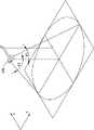
眩光(glare)作为一种光害,一般包括直接眩光和间接眩光。直接眩光是指来自视场中高亮度或没有充分遮蔽的眩光源/发光物发射的光线直接对眼睛造成的刺激,眩光源发光物处于被观察物的同一方向或邻近方向。间接眩光是指眩光源处于非观察方向产生的眩光,通常由高度光滑的表面的反射光引起。如图1所示,当光源101位于人眼102上方时,自人眼102所在垂直面103偏转45度至85度之间的范围内,光源101会对人眼102造成直接眩光。Glare, as a kind of light pollution, generally includes direct glare and indirect glare. Direct glare refers to the stimulation of the eyes directly by the light emitted from glare sources/luminous objects with high brightness or insufficient shielding in the field of view. Indirect glare refers to the glare produced by the glare source in a non-observing direction, usually caused by the reflected light of a highly smooth surface. As shown in FIG. 1 , when the
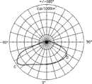
如图2所示,路灯201发射的光线以其自身为中心向路面进行投射,现有技术中可以实现路灯201在车辆行驶的X方向上的辐射范围大于与X方向垂直的Y方向的辐射范围,以有效地提高路灯201的光利用率。然而,路灯201在X方向上形成的辐射范围是以路灯201为中心对称分布的,即路灯201在X方向上向其两侧的辐射角θ1与θ2相等,通常θ1=θ2=70度,这会对人眼产生直接眩光,在此,辐射角也可称为半峰边角(half-peak side angle),是指以垂直路面为中心向左右两侧量测最大光强度的一半所得的角度,也就是光源所发出的发光强度为平面上最大发光强度的50%的光线与垂直线的夹角。在此,可参见图3所示路灯201的配光曲线,图中A点对应光线的光强度为该路灯201在0度到90度中最大光强度的50%,B点对应光线的光强度为该路灯201在0度到90度中的最大光强度,路灯201的辐射角约等于70度。由此可见,现有的路灯照明装置还是会对驾驶者的眼睛造成直接眩光。As shown in Figure 2, the light emitted by the
所以,有必要提供一种具有防眩光功能的路面照明装置。Therefore, it is necessary to provide a road lighting device with anti-glare function.
发明内容Contents of the invention
下面将以实施例说明一种具有防眩光功能的路面照明装置。A road surface lighting device with anti-glare function will be described below with an embodiment.
一种路面照明装置,其包括一个固态光源及一个光学元件。该固态光源用于发射光线的固态光源,其具有一个垂直于路面的中心对称轴,该中心对称轴沿路面延伸的方向将路面划分为行车靠近侧及行车远离侧。该光学元件与该固态光源相对设置,该固态光源射出的光线经由该光学元件射向路面,该光学元件用于将该固态光源发出的部分或全部光线向行车远离侧偏折,以使由该光学元件出射至行车靠近侧的光线的最大强度小于或等于由该光学元件出射至行车远离侧的光线的最大强度的百分之六十。A road lighting device includes a solid-state light source and an optical element. The solid-state light source is a solid-state light source for emitting light. It has a central symmetry axis perpendicular to the road surface, and the central symmetry axis divides the road surface into a driving approach side and a driving away side along the direction extending from the road surface. The optical element is arranged opposite to the solid-state light source, and the light emitted by the solid-state light source is directed to the road surface through the optical element. The maximum intensity of the light emitted by the optical element to the side close to the vehicle is less than or equal to 60% of the maximum intensity of the light emitted by the optical element to the side away from the vehicle.
相对于现有技术,所述路面照明装置发射的光线中,出射至行车靠近侧的光线的最大强度小于或等于由该光学元件出射至行车远离侧的光线的最大强度的百分之六十,当车辆由行车靠近侧驶向行车远离侧时,其不会直接对车辆驾驶员产生直接眩光的影响,从而有效保障了驾驶员的行车安全。Compared with the prior art, among the light rays emitted by the road surface lighting device, the maximum intensity of the light emitted to the side approaching the vehicle is less than or equal to 60% of the maximum intensity of the light emitted from the optical element to the side away from the vehicle, When the vehicle is driving from the driving-approaching side to the driving-away side, it will not directly affect the driver of the vehicle with direct glare, thereby effectively ensuring the driving safety of the driver.
附图说明Description of drawings
图1是现有技术中产生眩光的原理示意图。Fig. 1 is a schematic diagram of the principle of glare in the prior art.
图2是一种现有路灯对路面进行照射的状态示意图。Fig. 2 is a schematic diagram of the state of an existing street lamp illuminating the road surface.
图3是一种现有路灯的配光曲线图。Fig. 3 is a light distribution curve diagram of an existing street lamp.
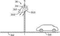
图4是本发明第一实施例提供的路面照明装置的使用状态示意图。Fig. 4 is a schematic diagram of the use state of the road lighting device provided by the first embodiment of the present invention.
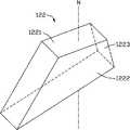
图5是本发明第一实施例提供的路面照明装置的结构示意图。Fig. 5 is a schematic structural diagram of the road lighting device provided by the first embodiment of the present invention.
图6是本发明第一实施例提供的路面照明装置的工作原理示意图。Fig. 6 is a schematic diagram of the working principle of the road lighting device provided by the first embodiment of the present invention.
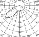
图7是图6所示路面照明装置的配光曲线图。Fig. 7 is a light distribution curve diagram of the road lighting device shown in Fig. 6 .
图8是图6所示路面照明装置另一变更实施方式的配光曲线图。Fig. 8 is a light distribution curve diagram of another modified embodiment of the road lighting device shown in Fig. 6 .
图9是本发明第二实施例提供的路面照明装置的工作原理示意图。Fig. 9 is a schematic diagram of the working principle of the road lighting device provided by the second embodiment of the present invention.
图10是本发明第二实施例提供的路面照明装置的结构示意图。Fig. 10 is a schematic structural diagram of a road lighting device provided by the second embodiment of the present invention.
图11是本发明第三实施例提供的路面照明装置的工作原理示意图。Fig. 11 is a schematic diagram of the working principle of the road lighting device provided by the third embodiment of the present invention.
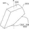
图12是本发明第三实施例提供的路面照明装置的结构示意图。Fig. 12 is a schematic structural diagram of a road lighting device provided by a third embodiment of the present invention.
图13是本发明第四实施例提供的路面照明装置的工作原理示意图。Fig. 13 is a schematic diagram of the working principle of the road lighting device provided by the fourth embodiment of the present invention.
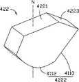
图14是本发明第四实施例提供的路面照明装置的结构示意图。Fig. 14 is a schematic structural diagram of a road lighting device provided by a fourth embodiment of the present invention.
图15是本发明第五实施例提供的路面照明装置的工作原理示意图。Fig. 15 is a schematic diagram of the working principle of the road lighting device provided by the fifth embodiment of the present invention.
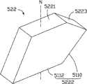
图16是本发明第五实施例提供的路面照明装置的结构示意图。Fig. 16 is a schematic structural diagram of a road lighting device provided by a fifth embodiment of the present invention.
图17是本发明第六实施例提供的路面照明装置的工作原理示意图。Fig. 17 is a schematic diagram of the working principle of the road lighting device provided by the sixth embodiment of the present invention.
图18是本发明第六实施例提供的路面照明装置的结构示意图。Fig. 18 is a schematic structural diagram of a road lighting device provided by the sixth embodiment of the present invention.
图19是本发明第七实施例提供的路面照明装置的结构示意图。Fig. 19 is a schematic structural diagram of a road lighting device provided by a seventh embodiment of the present invention.
具体实施方式Detailed ways
下面将结合附图,以对本发明实施例作进一步的详细说明。The embodiments of the present invention will be further described in detail below in conjunction with the accompanying drawings.
参见图4,本发明第一实施例提供的一种路面照明装置10,其用于对路面11进行照明,该照明装置10包括一个固态光源121及一个光学元件122。Referring to FIG. 4 , a road
固态光源121可为发光二极管(Light Emitting diode,LED)。发光二极管可为白光发光二极管或高功率固态光源,当然也可以为红光、蓝光等其它可发出不同色光的发光二极管。固态光源121也可为发光二极管芯片。The solid
光学元件122与固态光源121光学耦合,即固态光源121发射的光线直接进入光学元件122,并经由光学元件122的光学作用后射出。在本实施例中,固态光源121由一个灯杆15所固持,其具有一垂直于路面11的中心对称轴M。可以理解的是,该路面照明装置10也可包括一个用于安装该固态光源121的灯座(图未示),当将该灯座安装在该灯杆15上时,该灯杆可通过该灯座固持住该固态光源121。The
请一起参见图5,该光学元件122具体为四棱锥形,包括一个底面1221,一个相对于底面1221的出光面1222,以及一个连接在该底面1221与该出光面1222之间的侧面1223。该底面1221为一个长方形,该光学元件122具有一穿过该长方形几何中心的中心轴N。该出光面1222为一个与该底面1221成一预定夹角的斜面。该侧面1223包括四个与底面1221相接成一预定夹角的平面,具体为左右两个平面(由图10所示的视角观测)成一个张角,前后两个平面(由图10所示的视角观测)分别垂直于底面1221。固态光源121设置在光学元件122的底面1221上,其具有一个中心对称轴M,该中心对称轴M与该光学元件122的中心轴N相重合。该光学元件122通过其底面1221与该固态光源121相接合,使得其两者之间形成一个与该底面1221相重合的接合平面1221。Please refer to FIG. 5 together. The
请进一步参阅图6,该路面照明装置10设置于路面11,该固态光源121的中心对称轴M沿路面11延伸的方向将该路面11划分为行车靠近侧(car coming side)110及行车远离侧(carleaving side)112,在路面11上行驶的车辆18由行车靠近侧110驶向行车远离侧112。Please refer to FIG. 6 further, the road
当该固态光源121发光时,光线由该接合平面1221入射至该光学元件122中,进而由该光学元件122的出光面1222出射至外界。由于该出光面1222为斜面,当光线由出光面1222出射时,其部分或全部在该出光面1222发生折射,使得其向行车远离侧112偏折,因此,位于行车远离侧112受照较强,而位于行车靠近侧110受照较弱。当由该光学元件122出射至行车靠近侧110的光线的最大强度小于或等于由该光学元件122出射至行车远离侧112的光线的最大强度的百分之六十时,位于行车靠近侧110的车辆中的驾驶员不会受到直接眩光的影响。例如,图7为光学元件122其中一种实施方式所对应的配光曲线图,C点示出行车远离侧112的光线的最大强度约为950坎德拉(cd),D点示出行车靠近侧110的光线的最大强度约为550坎德拉。当驾驶员位于行车靠近侧110时,其眼睛受到的光线刺激没有超出正常范围,因此不会受到直接眩光的影响,而当汽车由行车靠近侧110驶向行车远离侧112时,驾驶员背向光线照射方向,其也不会受到直接眩光的影响。When the solid-
该出光面1222相对该接合平面1221的倾斜程度可根据需要进行调整,图8示出光学元件122的出光面1222的倾斜程度经变更后,照明装置10所对应的配光曲线图,其中,E点示出行车远离侧112的光线的最大强度约为700坎德拉(cd),D点示出行车靠近侧110的光线的最大强度约为135坎德拉。由于由该光学元件122出射至行车靠近侧110,且与该固态光源121的中心对称轴M的夹角在45~85度之间的光线的最大强度小于(也可等于)由该光学元件122出射至行车远离侧112的光线的最大强度的百分之二十,所以其实施效果更佳。The inclination of the light-emitting
可以理解的是,光学元件122的侧面1223上还可以设置一反射层以进一步提高光利用效率。It can be understood that a reflective layer may also be provided on the
光学元件122可采用透光材料如塑料,玻璃等制成。当该固态光源121为发光二极管芯片时,光学元件122可相应为包覆该发光二极管芯片121的封装体,其制作材料可为硅胶(Silicone)、压克力(PMMA)、聚碳酸酯(PC)、环氧树脂(Epoxy)或聚对苯二甲酸乙二醇酯(polyethylene terephthalate,PET)等。The
第一实施例中路面照明装置10所包含的光学元件的结构并不限于此,其还可以采用其它设计以具有防眩光功能,以下将举例说明几种具有不同光学元件的路面照明装置。The structure of the optical elements included in the
参见图9及图10,本发明第二实施例提供的一种路面照明装置20,其包括一固态光源221,及一个与固态光源221光学耦合的光学元件222。光学元件222具有一个底面2221,一个出光面2222,以及一个侧面2223。该光学元件222与第一实施例所述的光学元件122相类似,不同之处在于:光学元件222的出光面2222为一个沿路面11所在的方向延伸的曲面,该出光面2222相对接合平面2221的斜率由行车靠近侧210向行车远离侧212逐渐变大。Referring to FIG. 9 and FIG. 10 , a road lighting device 20 provided by the second embodiment of the present invention includes a solid-state light source 221 and an
参见图11及图12,本发明第三实施例提供的一种路面照明装置30,其包括一个固态光源321,一个与固态光源321光学耦合的光学元件322。光学元件322具有一个底面3221,一个出光面3222,以及一个侧面3223。该照明装置30与第一实施例所提供的路面照明装置10相类似,不同之处在于:光学元件322的出光面3222由一个第一面3110及一个第二面3112相连接所形成,该第一面3110为一个与该底面3221成一预定夹角的斜面,该第二面3112为与底面3221相平行的平面,该第一面3110与该第二面3112分处中心轴N的两侧,其中,该第一面3110位于该光学元件322对应于行车靠近侧310的一侧,该第二面3112位于该光学元件322对应于行车远离侧312的另一侧。Referring to FIG. 11 and FIG. 12 , a
该光学元件的出光面也可为平面与曲面的结合,如图13及图14所示,本发明第四实施例提供的一种路面照明装置40,其包括一固态光源421,一个与固态光源421光学耦合的光学元件422。光学元件422具有一个底面4221,一个出光面4222,以及一个侧面4223,其中,出光面4222由一个第一面4110及一个第二面4112相连接所形成。该照明装置40与上述第三实施例所提供的路面照明装置30相类似,不同之处在于:该第二面4112为一个向外凸出的曲面。The light-emitting surface of the optical element can also be a combination of a plane and a curved surface. As shown in Figure 13 and Figure 14, a
参见图15及图16所示,本发明第五实施例提供的一种路面照明装置50,其包括一固态光源521,一个与固态光源521光学耦合的光学元件522。光学元件522具有一个底面5221,一个出光面5222,以及一个侧面5223,其中,出光面5222由一个第一面5110及一个第二面5112相连接所形成。该照明装置50与上述第三实施例所提供的路面照明装置30相类似,不同之处在于:该第一面5110为一个向内凹陷的曲面,且该第一面5110相对该底面5221的斜率由行车靠近侧510向行车远离侧512逐渐变大。Referring to FIG. 15 and FIG. 16 , a
参见图17及图18所示,本发明第六实施例提供的一种路面照明装置60,其包括一固态光源621,一个与固态光源621光学耦合的光学元件622。光学元件622具有一个底面6221,一个出光面6222,以及一个侧面6223,其中,出光面6222由一个第一面6110及一个第二面6112相连接所形成。该照明装置60与上述第三实施例所提供的路面照明装置30相类似,不同之处在于:该第一面6110为一个与该底面6221成一预定夹角的斜面,该第二面6112为一个向内凹陷的曲面。Referring to FIG. 17 and FIG. 18 , a
参见图19,本发明第七实施例进一步提供了一种路面照明装置70,其用于对路面71进行照明。该照明装置70包括多个固态光源721及一个光学元件阵列72。Referring to FIG. 19 , the seventh embodiment of the present invention further provides a road
该光学元件阵列72由多个光学元件722依序排列所组成。每个光学元件722具有一个底面7221,一个出光面7222,以及一个侧面7223。该光学元件722与第一实施例所提供的光学元件122相类似,差别在于:侧面7223所包含的四个平面分别垂直于底面7221。The optical element array 72 is composed of a plurality of
该多个光学元件722的多个底面7221位于同一个平面内,该多个固态光源721对应于该多个光学元件722,每个固态光源721设置在与其对应的光学元件722的底面7221上。The plurality of
该光学元件阵列72可将多个固态光源721所发出的光向行车远离侧712偏折,使得驾驶员不会受到直接眩光影响。The optical element array 72 can deflect the light emitted by the plurality of solid-
可以理解的是,对于本领域的普通技术人员来说,可以根据本发明的技术构思做出其它各种对应的改变与变形,例如:将第二至第六实施例中的光学元件进行适当变更,并利用多个光学元件相互结合形成与第七实施例所述光学元件阵列72相类似的光学元件阵列,从而可与多个固态光源一起组成其它路面照明装置,以对路面进行照明并达到防眩光的目的,而所有这些改变与变形都应属于本发明权利要求的保护范围。It can be understood that, for those skilled in the art, various other corresponding changes and deformations can be made according to the technical concept of the present invention, for example: appropriate changes to the optical elements in the second to sixth embodiments , and use a plurality of optical elements to combine with each other to form an optical element array similar to the optical element array 72 in the seventh embodiment, so that other road lighting devices can be formed together with a plurality of solid-state light sources to illuminate the road surface and achieve anti- The purpose of glare, and all these changes and deformations should belong to the protection scope of the claims of the present invention.
Claims (5)
Translated fromChinesePriority Applications (2)
| Application Number | Priority Date | Filing Date | Title |
|---|---|---|---|
| CN2009103047140ACN101963321B (en) | 2009-07-23 | 2009-07-23 | Road illuminating device |
| US12/700,928US20110019405A1 (en) | 2009-07-23 | 2010-02-05 | Street lamp |
Applications Claiming Priority (1)
| Application Number | Priority Date | Filing Date | Title |
|---|---|---|---|
| CN2009103047140ACN101963321B (en) | 2009-07-23 | 2009-07-23 | Road illuminating device |
Publications (2)
| Publication Number | Publication Date |
|---|---|
| CN101963321A CN101963321A (en) | 2011-02-02 |
| CN101963321Btrue CN101963321B (en) | 2012-06-27 |
Family
ID=43497180
Family Applications (1)
| Application Number | Title | Priority Date | Filing Date |
|---|---|---|---|
| CN2009103047140AExpired - Fee RelatedCN101963321B (en) | 2009-07-23 | 2009-07-23 | Road illuminating device |
Country Status (2)
| Country | Link |
|---|---|
| US (1) | US20110019405A1 (en) |
| CN (1) | CN101963321B (en) |
Families Citing this family (9)
| Publication number | Priority date | Publication date | Assignee | Title |
|---|---|---|---|---|
| US8485684B2 (en)* | 2011-05-13 | 2013-07-16 | GE Lighting Solutions, LLC | LED roadway luminaire |
| CN102937256A (en)* | 2011-08-14 | 2013-02-20 | 黄于民 | Lateral light distribution street lamp |
| TWM422633U (en)* | 2011-09-22 | 2012-02-11 | Arex Twn Internat Co Ltd | The luminaire with asymmetric luminous intensity |
| CN102384430B (en)* | 2011-11-08 | 2013-07-24 | 杭州照相机械研究所 | Guardrail lamp and guardrail lamp lens |
| US9192029B2 (en)* | 2013-03-14 | 2015-11-17 | Abl Ip Holding Llc | Adaptive optical distribution system |
| US9192026B2 (en) | 2013-03-14 | 2015-11-17 | Abl Ip Holding Llc | Veiling zone control |
| WO2014162681A1 (en)* | 2013-04-03 | 2014-10-09 | 株式会社小糸製作所 | Road lighting device |
| US9348080B1 (en)* | 2014-11-18 | 2016-05-24 | Quarkstar Llc | Wall wash luminaire with light guide and optical element therefore |
| US10895784B2 (en)* | 2016-12-14 | 2021-01-19 | Magic Leap, Inc. | Patterning of liquid crystals using soft-imprint replication of surface alignment patterns |
Citations (3)
| Publication number | Priority date | Publication date | Assignee | Title |
|---|---|---|---|---|
| EP0085145A1 (en)* | 1982-02-01 | 1983-08-10 | Siemens Aktiengesellschaft | Broad-beam axially symmetric street lamp |
| CN2544173Y (en)* | 2002-04-09 | 2003-04-09 | 苑泉声 | Reflection road lamp with dizzy-proof board lamp shade |
| CN1704641A (en)* | 2004-05-26 | 2005-12-07 | 微杠杆有限公司 | Reflector bowl, manufacturing method thereof, and street lighting structure using the reflector bowl |
Family Cites Families (6)
| Publication number | Priority date | Publication date | Assignee | Title |
|---|---|---|---|---|
| CA1047014A (en)* | 1974-04-22 | 1979-01-23 | Dale E. Welty | Luminaire and luminaire reflector for use in an off-the-roadway lighting arrangement |
| US4288847A (en)* | 1979-06-18 | 1981-09-08 | Elmer William B | Compound beam illuminating |
| US7329982B2 (en)* | 2004-10-29 | 2008-02-12 | 3M Innovative Properties Company | LED package with non-bonded optical element |
| US7618163B2 (en)* | 2007-04-02 | 2009-11-17 | Ruud Lighting, Inc. | Light-directing LED apparatus |
| US7828456B2 (en)* | 2007-10-17 | 2010-11-09 | Lsi Industries, Inc. | Roadway luminaire and methods of use |
| TWI336386B (en)* | 2008-03-07 | 2011-01-21 | Ind Tech Res Inst | Illumination device |
- 2009
- 2009-07-23CNCN2009103047140Apatent/CN101963321B/ennot_activeExpired - Fee Related
- 2010
- 2010-02-05USUS12/700,928patent/US20110019405A1/ennot_activeAbandoned
Patent Citations (3)
| Publication number | Priority date | Publication date | Assignee | Title |
|---|---|---|---|---|
| EP0085145A1 (en)* | 1982-02-01 | 1983-08-10 | Siemens Aktiengesellschaft | Broad-beam axially symmetric street lamp |
| CN2544173Y (en)* | 2002-04-09 | 2003-04-09 | 苑泉声 | Reflection road lamp with dizzy-proof board lamp shade |
| CN1704641A (en)* | 2004-05-26 | 2005-12-07 | 微杠杆有限公司 | Reflector bowl, manufacturing method thereof, and street lighting structure using the reflector bowl |
Non-Patent Citations (1)
| Title |
|---|
| JP特开2000-322903A 2000.11.24 |
Also Published As
| Publication number | Publication date |
|---|---|
| CN101963321A (en) | 2011-02-02 |
| US20110019405A1 (en) | 2011-01-27 |
Similar Documents
| Publication | Publication Date | Title |
|---|---|---|
| CN101963321B (en) | Road illuminating device | |
| CN101626055B (en) | LED package | |
| US7845808B2 (en) | Illuminating device | |
| TWI535978B (en) | Optical lens and lighting element using same | |
| US8500309B2 (en) | LED unit | |
| CN106247278A (en) | Light guiding lens and lamps apparatus for vehicle | |
| CN102032526A (en) | LED module | |
| CN103322503A (en) | Optical lens and LED lamp source device using same | |
| CN101451678A (en) | Solid lighting device | |
| TWI479107B (en) | Led light distributing lens and light source apparatus using the same | |
| TW201443372A (en) | Light-guiding structure and light-emitting device | |
| JP6297911B2 (en) | Light emitting device package and lighting device including the same | |
| CN103900006A (en) | Led vehicle lamp | |
| US8246194B2 (en) | Illumination apparatus | |
| CN101846288A (en) | Illuminating device | |
| CN105276482B (en) | Lighting device and automobile with same | |
| CN102062883A (en) | Lens, lighting device using same and street lamp | |
| US20150318456A1 (en) | Optical lens device | |
| US8921880B2 (en) | Light emitting diode light source device | |
| CN101737709A (en) | Special-shaped light distribution curve light-emitting diode | |
| CN101078477A (en) | Energy-saving road lighting member with microstructure optical system scattering element | |
| CN201795423U (en) | Optical lens, light source module and street light | |
| CN101532637B (en) | lighting device | |
| US9057805B2 (en) | Lens and LED unit using the same | |
| TWI852758B (en) | Illumination device for lighting pedestrian crossing |
Legal Events
| Date | Code | Title | Description |
|---|---|---|---|
| C06 | Publication | ||
| PB01 | Publication | ||
| C10 | Entry into substantive examination | ||
| SE01 | Entry into force of request for substantive examination | ||
| C14 | Grant of patent or utility model | ||
| GR01 | Patent grant | ||
| C56 | Change in the name or address of the patentee | ||
| CP01 | Change in the name or title of a patent holder | Address after:201600 Shanghai City, Songjiang District Songjiang Industrial Zone West science and Technology Industrial Park No. 500 Wen Ji Lu Patentee after:Foxsemicon Semiconductor Precision (Shanghai) Inc. Patentee after:Foxsemicon Integrated Technology Inc. Address before:201600 Shanghai City, Songjiang District Songjiang Industrial Zone West science and Technology Industrial Park No. 500 Wen Ji Lu Patentee before:Foxsemicon Semiconductor Precision (Shanghai) Inc. Patentee before:Foxsemicon Integrated Technology Inc. | |
| ASS | Succession or assignment of patent right | Free format text:FORMER OWNER: FOXSEMICON INTEGRATED TECHNOLOGY INC. Effective date:20141126 Owner name:NANTONG CHIAN RAILWAY HUAYU ELECTRIC CO., LTD. Free format text:FORMER OWNER: FUSHIMAI SEMICONDUCTOR PRECISION INDUSTRY (SHANGHAI) CO., LTD. Effective date:20141126 | |
| C41 | Transfer of patent application or patent right or utility model | ||
| COR | Change of bibliographic data | Free format text:CORRECT: ADDRESS; FROM: 201600 SONGJIANG, SHANGHAI TO: 226500 NANTONG, JIANGSU PROVINCE | |
| TR01 | Transfer of patent right | Effective date of registration:20141126 Address after:226500 No. 69 East Zhongshan Road, Rugao, Jiangsu Patentee after:Nantong Zhongtie Huayu Electrics Co., Ltd. Address before:201600 Shanghai City, Songjiang District Songjiang Industrial Zone West science and Technology Industrial Park No. 500 Wen Ji Lu Patentee before:Foxsemicon Semiconductor Precision (Shanghai) Inc. Patentee before:Foxsemicon Integrated Technology Inc. | |
| CF01 | Termination of patent right due to non-payment of annual fee | Granted publication date:20120627 Termination date:20180723 | |
| CF01 | Termination of patent right due to non-payment of annual fee |