CN101961256A - Devices and methods for repairing tissue - Google Patents
Devices and methods for repairing tissueDownload PDFInfo
- Publication number
- CN101961256A CN101961256ACN2010102365878ACN201010236587ACN101961256ACN 101961256 ACN101961256 ACN 101961256ACN 2010102365878 ACN2010102365878 ACN 2010102365878ACN 201010236587 ACN201010236587 ACN 201010236587ACN 101961256 ACN101961256 ACN 101961256A
- Authority
- CN
- China
- Prior art keywords
- fixed component
- opening
- stitching thread
- separately
- tissue
- Prior art date
- Legal status (The legal status is an assumption and is not a legal conclusion. Google has not performed a legal analysis and makes no representation as to the accuracy of the status listed.)
- Pending
Links
Images


Classifications
- A—HUMAN NECESSITIES
- A61—MEDICAL OR VETERINARY SCIENCE; HYGIENE
- A61B—DIAGNOSIS; SURGERY; IDENTIFICATION
- A61B17/00—Surgical instruments, devices or methods
- A61B17/04—Surgical instruments, devices or methods for suturing wounds; Holders or packages for needles or suture materials
- A61B17/0401—Suture anchors, buttons or pledgets, i.e. means for attaching sutures to bone, cartilage or soft tissue; Instruments for applying or removing suture anchors
- A—HUMAN NECESSITIES
- A61—MEDICAL OR VETERINARY SCIENCE; HYGIENE
- A61B—DIAGNOSIS; SURGERY; IDENTIFICATION
- A61B17/00—Surgical instruments, devices or methods
- A61B17/04—Surgical instruments, devices or methods for suturing wounds; Holders or packages for needles or suture materials
- A61B17/0469—Suturing instruments for use in minimally invasive surgery, e.g. endoscopic surgery
- A—HUMAN NECESSITIES
- A61—MEDICAL OR VETERINARY SCIENCE; HYGIENE
- A61B—DIAGNOSIS; SURGERY; IDENTIFICATION
- A61B17/00—Surgical instruments, devices or methods
- A61B2017/00004—(bio)absorbable, (bio)resorbable or resorptive
- A—HUMAN NECESSITIES
- A61—MEDICAL OR VETERINARY SCIENCE; HYGIENE
- A61B—DIAGNOSIS; SURGERY; IDENTIFICATION
- A61B17/00—Surgical instruments, devices or methods
- A61B17/04—Surgical instruments, devices or methods for suturing wounds; Holders or packages for needles or suture materials
- A61B17/0401—Suture anchors, buttons or pledgets, i.e. means for attaching sutures to bone, cartilage or soft tissue; Instruments for applying or removing suture anchors
- A61B2017/0409—Instruments for applying suture anchors
- A—HUMAN NECESSITIES
- A61—MEDICAL OR VETERINARY SCIENCE; HYGIENE
- A61B—DIAGNOSIS; SURGERY; IDENTIFICATION
- A61B17/00—Surgical instruments, devices or methods
- A61B17/04—Surgical instruments, devices or methods for suturing wounds; Holders or packages for needles or suture materials
- A61B17/0401—Suture anchors, buttons or pledgets, i.e. means for attaching sutures to bone, cartilage or soft tissue; Instruments for applying or removing suture anchors
- A61B2017/0417—T-fasteners
- A—HUMAN NECESSITIES
- A61—MEDICAL OR VETERINARY SCIENCE; HYGIENE
- A61B—DIAGNOSIS; SURGERY; IDENTIFICATION
- A61B17/00—Surgical instruments, devices or methods
- A61B17/04—Surgical instruments, devices or methods for suturing wounds; Holders or packages for needles or suture materials
- A61B17/0401—Suture anchors, buttons or pledgets, i.e. means for attaching sutures to bone, cartilage or soft tissue; Instruments for applying or removing suture anchors
- A61B2017/0446—Means for attaching and blocking the suture in the suture anchor
- A61B2017/0459—Multiple holes in the anchor through which the suture extends and locking the suture when tension is applied
- A—HUMAN NECESSITIES
- A61—MEDICAL OR VETERINARY SCIENCE; HYGIENE
- A61B—DIAGNOSIS; SURGERY; IDENTIFICATION
- A61B17/00—Surgical instruments, devices or methods
- A61B17/04—Surgical instruments, devices or methods for suturing wounds; Holders or packages for needles or suture materials
- A61B17/0401—Suture anchors, buttons or pledgets, i.e. means for attaching sutures to bone, cartilage or soft tissue; Instruments for applying or removing suture anchors
- A61B2017/0464—Suture anchors, buttons or pledgets, i.e. means for attaching sutures to bone, cartilage or soft tissue; Instruments for applying or removing suture anchors for soft tissue
- A—HUMAN NECESSITIES
- A61—MEDICAL OR VETERINARY SCIENCE; HYGIENE
- A61B—DIAGNOSIS; SURGERY; IDENTIFICATION
- A61B17/00—Surgical instruments, devices or methods
- A61B17/04—Surgical instruments, devices or methods for suturing wounds; Holders or packages for needles or suture materials
- A61B17/0469—Suturing instruments for use in minimally invasive surgery, e.g. endoscopic surgery
- A61B2017/0475—Suturing instruments for use in minimally invasive surgery, e.g. endoscopic surgery using sutures having a slip knot
- A—HUMAN NECESSITIES
- A61—MEDICAL OR VETERINARY SCIENCE; HYGIENE
- A61B—DIAGNOSIS; SURGERY; IDENTIFICATION
- A61B17/00—Surgical instruments, devices or methods
- A61B17/04—Surgical instruments, devices or methods for suturing wounds; Holders or packages for needles or suture materials
- A61B17/06—Needles ; Sutures; Needle-suture combinations; Holders or packages for needles or suture materials
- A61B2017/06052—Needle-suture combinations in which a suture is extending inside a hollow tubular needle, e.g. over the entire length of the needle
Landscapes
- Health & Medical Sciences (AREA)
- Surgery (AREA)
- Life Sciences & Earth Sciences (AREA)
- Medical Informatics (AREA)
- Nuclear Medicine, Radiotherapy & Molecular Imaging (AREA)
- Engineering & Computer Science (AREA)
- Biomedical Technology (AREA)
- Heart & Thoracic Surgery (AREA)
- Molecular Biology (AREA)
- Animal Behavior & Ethology (AREA)
- General Health & Medical Sciences (AREA)
- Public Health (AREA)
- Veterinary Medicine (AREA)
- Rheumatology (AREA)
- Surgical Instruments (AREA)
- Prostheses (AREA)
Abstract
Description
Translated fromChinese技术领域technical field
本发明整体涉及用于修复组织的设备和方法。更具体地讲,本发明涉及用于对组织缺陷进行关节镜式修复的缝合线锚定设备和方法。The present invention generally relates to devices and methods for repairing tissue. More particularly, the present invention relates to suture anchoring devices and methods for arthroscopic repair of tissue defects.
背景技术Background technique
多种损伤和病症需要进行软组织损伤修复,或将软组织再附着到骨和/或外围组织上。例如,一旦健康组织从骨上撕裂,例如肩袖肌腱部分或完全从肱骨上撕裂(肩袖撕裂),则往往需要通过外科手术将组织再附着到骨上,以允许进行愈合和自然再附着。已经开发出多种设备和方法以用于进行这些外科手术修复,较成功的方法中的一些包括使用缝合线锚定件,或一般为“缝合线固定构件”,其通常包括具有一个或多个缝合线连接特征和组织或骨接合特征的锚定主体,该组织或骨接合特征将缝合线锚定件保持在组织或骨内或与其相邻。根据具体损伤情况,可以使用连接到一段或多段缝合线或通过该一段或多段缝合线互连的一个或多个缝合线锚定件进行修复。A variety of injuries and conditions require repair of soft tissue damage, or reattachment of soft tissue to bone and/or surrounding tissues. For example, once healthy tissue is torn from the bone, such as the rotator cuff tendon partially or completely from the humerus (rotator cuff tear), surgery is often required to reattach the tissue to the bone to allow healing and natural healing to occur. Reattach. A variety of devices and methods have been developed for performing these surgical repairs, some of the more successful methods involving the use of suture anchors, or generally "suture fixation members," which typically consist of one or more An anchoring body for a suture attachment feature and a tissue or bone engaging feature that holds the suture anchor within or adjacent to the tissue or bone. Depending on the specific injury, one or more suture anchors connected to or interconnected by one or more lengths of suture may be used for repair.
当单一类型的组织物质中(例如膝半月板中)发生撕裂(半月板撕裂)时,也可能需要外科手术。修复此类撕裂的一种方法是将一定长度的缝合线穿过组织,且扎系缝合线来缝合组织。缝合线也可与一个或多个缝合线锚定件结合使用,以修复此类组织撕裂。可使用修复手术期间外科医生打的结将缝合线紧固到缝合线锚定件或组织上,或使用“无结”设备和方法,在这种情况下外科医生在外科手术期间无需打结即能够将一个或多个锚定件或一根或多根缝合线连接和拉紧。无结锚定对诸如内窥镜式修复或关节镜式修复之类的微创外科手术尤其实用,在这些手术中,外科医生必须使用插入小直径套管或内窥镜管的工具来远程操纵位于手术部位的缝合线,这可能使得打结过程困难而乏味。Surgery may also be required when a tear occurs in a single type of tissue mass (eg, in the meniscus of the knee) (meniscal tear). One method of repairing such tears is to thread a length of suture through the tissue and tie the suture to close the tissue. Sutures may also be used in conjunction with one or more suture anchors to repair such tissue tears. The suture can be secured to the suture anchor or tissue using a knot tied by the surgeon during the revision procedure, or using "knotless" devices and methods, in which case the surgeon does not need to tie a knot during the surgical procedure to secure the suture to the suture anchor or tissue. One or more anchors or one or more sutures can be attached and tensioned. Knotless anchoring is especially useful for minimally invasive surgical procedures such as endoscopic or arthroscopic repairs, where the surgeon must manipulate them remotely using tools inserted into small diameter cannulae or endoscopic tubing Sutures located at the surgical site, which can make the knotting process difficult and tedious.
利用了多种方法,从而得到无结锚定,包括布置于组织中时自动将缝合线锁定到位的锚定件、锚定件布置后即可控制地将缝合线锁定到锚定件上的锚定元件、能使缝合线仅沿一个方向滑动穿过其中的设备、以及外科医生使用简单工具或拉紧一股或多股从线结延伸的缝合线即可拉紧的预成形结。Utilizes a variety of methods to achieve knot-free anchoring, including anchors that automatically lock the suture in place when deployed in tissue, anchors that controllably lock the suture to the anchor once the anchor is deployed A fixed element, a device through which the suture can be slid in only one direction, and a preformed knot that can be tensioned by the surgeon using simple tools or by tightening one or more strands of suture extending from the knot.
虽然已开发出许多用于修复撕裂组织的缝合线锚定系统,但现有设备并不是没有缺陷。一些结或其他锚定元件可能会在所修复组织的表面、尤其是面向接触骨的承重表面(例如股骨与半月板之间的界面)上“隆起”,并且妨碍(例如)关节连接组织的移动和愈合,或在未达到最佳修复的某些情况下,外科医生不能完全控制结相对于锚定件或附近组织的位置。在两个或更多个缝合线锚定件通过缝合线接合以修复损伤的外科手术中,沿着将锚定件彼此连接的缝合线设置的任何结或连接的缝合线段都可成为限制外科手术修复的极限强度或造成外科手术创伤的应力点。While a number of suture anchoring systems have been developed for repairing torn tissue, existing devices are not without drawbacks. Some knots or other anchoring elements may "bump" on the surface of the repaired tissue, especially the load-bearing surface facing the contacting bone (eg, the interface between the femur and the meniscus) and interfere with the movement of, for example, articulating tissue and healing, or in some cases of suboptimal repair, the surgeon does not have complete control over the position of the knot relative to the anchor or nearby tissue. In surgical procedures in which two or more suture anchors are joined by sutures to repair damage, any knots or connected suture segments placed along the suture connecting the anchors to each other can become a surgical limitation. The ultimate strength of the repair or the stress point causing surgical trauma.
因此,仍然存在对用于修复撕裂或受损组织的改善方法和设备的需求,尤其是对适于采用缝合线锚定件对撕裂组织或换句话讲受损组织进行关节镜式修复的改善方法和设备的需求。另外,仍然存在对这样的方法和设备的需求,该方法和设备可降低对正在修复的组织造成损伤的风险,并且提供薄型设备以消除对关节移动和愈合的干涉作用。Accordingly, there remains a need for improved methods and devices for repairing torn or damaged tissue, particularly those adapted for arthroscopic repair of torn or otherwise damaged tissue using suture anchors Improvement methods and equipment needs. Additionally, there remains a need for methods and devices that reduce the risk of damage to the tissue being repaired and provide low profile devices that eliminate interference with joint movement and healing.
发明内容Contents of the invention
因此,本发明提供了用于修复受损组织的缝合线锚定设备和方法的实施例。根据本发明的设备包括第一固定构件和第二固定构件,其中第一固定构件和第二固定构件中的每一个都具有第一表面、相对的第二表面以及第一表面与第二表面之间限定的第一贯穿开口和第二贯穿开口。挠性元件连接第一固定构件和第二固定构件,挠性元件具有第一末端、第二末端以及两者间的长度,其中长度从第一末端延伸,按顺序沿着缝合线的第一末端部分,穿过第一固定构件中的第一开口从各自的第一表面延伸至各自的第二表面,穿过第二固定构件中的第一开口从各自的第二表面延伸至各自的第一表面,穿过第二固定构件中的第二开口从各自的第一表面延伸至各自的第二表面,穿过第一固定构件中的第二开口从各自的第二表面延伸至各自的第一表面,且沿着缝合线的第二末端部分延伸。第一固定构件具有各自的第一表面与第二表面之间限定的第三贯穿开口。第一末端部分与第二末端部分之间形成滑动锁定结,其中第一末端部分设置为可滑动地穿过结并且从结延伸,且穿过第三开口从第一表面延伸至第二表面。Accordingly, the present invention provides embodiments of suture anchoring devices and methods for repairing damaged tissue. The device according to the present invention comprises a first fixing member and a second fixing member, wherein each of the first fixing member and the second fixing member has a first surface, an opposite second surface and a gap between the first surface and the second surface. A first through opening and a second through opening defined between them. A flexible element connects the first fixation member and the second fixation member, the flexible element has a first end, a second end, and a length therebetween, wherein the length extends from the first end, sequentially along the first end of the suture A portion extending from a respective first surface to a respective second surface through a first opening in the first fixation member, and extending from a respective second surface to a respective first surface through a first opening in the second fixation member. Surfaces extending from respective first surfaces to respective second surfaces through second openings in the second fixation member, extending from respective second surfaces to respective first surfaces through second openings in the first fixation member surface, and extends along the second end portion of the suture. The first fixing members have third through openings defined between respective first and second surfaces. A slide lock knot is formed between the first end portion and the second end portion, wherein the first end portion is configured to slide slidably pass through and extend from the knot and extend from the first surface to the second surface through the third opening.
在本发明的一个方面,穿过第一固定构件的第一开口、第二开口和第三开口沿着各自的第一表面和第二表面基本上呈直线排列。优选地,第一固定构件和第二固定构件包括每一个各自的表面上相邻开口之间的倒圆表面,以用于挠性元件沿其滑动。在本发明的一个方面,开口中的每一个都具有大致圆形的横截面。作为另外一种选择,开口中的一个或多个具有细长的横截面。优选地,相对于第一固定构件施加到第二末端部分的张力能够有效地缩短沿着连接第一固定构件和第二固定构件的挠性构件的第一固定构件与第二固定构件之间的距离。In one aspect of the present invention, the first opening, the second opening and the third opening through the first fixing member are aligned substantially linearly along the respective first and second surfaces. Preferably, the first fixation member and the second fixation member comprise rounded surfaces between adjacent openings on each respective surface for the flexible element to slide therealong. In one aspect of the invention, each of the openings has a generally circular cross-section. Alternatively, one or more of the openings has an elongated cross-section. Preferably, the tension applied to the second end portion relative to the first securing member is effective to shorten the distance between the first securing member and the second securing member along the flexible member connecting the first securing member and the second securing member. distance.
在本发明的一个方面,第一固定构件和第二固定构件还包括各自的第一表面和第二表面中的每一个中的基本线性的凹槽,其中凹槽从各自的表面的第一末端延伸至各自的表面的相对的末端,第二表面中的凹槽与第一表面中的凹槽大致平行。递送装置具有细长的递送构件,其内纵向可滑动地接纳由挠性元件连接的第一固定构件和第二固定构件中的每一个的至少一部分,优选地,固定构件中的凹槽与递送构件中的狭槽滑动接合。In one aspect of the invention, the first fixation member and the second fixation member further comprise a substantially linear groove in each of the respective first and second surfaces, wherein the groove extends from the first end of the respective surface Extending to opposite ends of the respective surfaces, the grooves in the second surface are substantially parallel to the grooves in the first surface. The delivery device has an elongated delivery member within which longitudinally slidably receives at least a portion of each of the first and second fixation members connected by a flexible element, preferably a groove in the fixation member in contact with the delivery member. The slots in the members are in sliding engagement.
优选地,挠性元件包括缝合线。在本发明的一个方面,挠性元件包含聚乙烯。在本发明的另一方面,挠性元件包含聚乙烯和可生物吸收的聚合物,优选地,该可生物吸收的聚合物包含聚二氧杂环己酮(polydioxanone)。Preferably, the flexible element comprises suture. In one aspect of the invention, the flexible element comprises polyethylene. In another aspect of the invention, the flexible element comprises polyethylene and a bioabsorbable polymer, preferably the bioabsorbable polymer comprises polydioxanone.
优选地,滑动锁定结为拢帆索结。Preferably, the slide lock knot is a rigging knot.
优选地,提供包括套管的递送装置,其中套管具有近端和远端以及壁中的从远端朝近端延伸的纵向狭槽,并且套管由沿着狭槽的相对纵向边缘限定。第一固定装置和第二固定装置沿着狭槽接纳在套管中,其中狭槽边缘在第一固定装置和第二固定装置中的每一个中的各自的凹槽中滑动接合。优选地,调配杆设置在套管中,柄部以机械方式连接至套管近端,可手动操纵的构件与柄部连接以将套管中的调配杆向远侧平移,以用于将第一固定装置和第二固定装置中的一个滑动地排出套管远端。Preferably, a delivery device is provided comprising a cannula, wherein the cannula has proximal and distal ends and a longitudinal slot in the wall extending from the distal end towards the proximal end, and the cannula is defined by opposing longitudinal edges along the slot. The first and second securing means are received in the sleeve along the slot, wherein the edges of the slot slideably engage in respective grooves in each of the first and second securing means. Preferably, the deployment rod is disposed in the cannula, the handle is mechanically connected to the proximal end of the cannula, and the manually operable member is connected to the handle to translate the deployment rod in the cannula distally for moving the first One of the first fixation device and the second fixation device slides out of the distal end of the cannula.
根据本发明的设备包括第一固定构件和第二固定构件。第一固定构件和第二固定构件中的每一个都具有第一表面和相对的第二表面,第一固定装置的第一表面与第二表面之间限定的第一贯穿开口、第二贯穿开口和第三贯穿开口,以及第二固定装置的第一表面与第二表面之间限定的一个或多个贯穿开口。挠性元件连接第一固定构件和第二固定构件。挠性元件具有第一末端、第二末端以及两者间的长度,其中长度从第一末端延伸,按顺序沿着缝合线的第一末端部分,穿过第一固定构件中的第一开口从各自的第一表面延伸至各自的第二表面,穿过第二固定构件中的一个或多个开口中的至少一个从各自的第二表面延伸至各自的第一表面,穿过第一固定构件中的第二开口从各自的第二表面延伸至各自的第一表面,且沿着缝合线的第二末端部分延伸。第一末端部分与第二末端部分之间形成滑动锁定结,第二末端部分从该结延伸并且穿过第三开口从第一表面延伸至第二表面。The device according to the invention comprises a first fixing member and a second fixing member. Each of the first fixing member and the second fixing member has a first surface and an opposite second surface, a first through opening defined between the first surface and the second surface of the first fixing device, a second through opening and a third through opening, and one or more through openings defined between the first surface and the second surface of the second fixture. A flexible element connects the first fixation member and the second fixation member. The flexible element has a first end, a second end, and a length therebetween, wherein the length extends from the first end, sequentially along the first end portion of the suture, through the first opening in the first fixation member, from the the respective first surface extends to the respective second surface through at least one of the one or more openings in the second fixation member extending from the respective second surface to the respective first surface through the first fixation member The second opening in extends from the respective second surface to the respective first surface and along the second end portion of the suture. A slide lock knot is formed between the first end portion and the second end portion, the second end portion extending from the knot and extending from the first surface to the second surface through the third opening.
根据本发明的设备包括第一固定构件和第二固定构件,第一固定构件和第二固定构件通过两者间延伸的两段连续缝合线连接。第一固定构件具有第一表面和相对的第二表面。两段缝合线彼此连续,并且可滑动穿过贯穿第二固定构件的开口。两段缝合线中的每一个都贯穿第一固定构件中的各自的第一贯穿开口和第二贯穿开口,从第二表面延伸至第一表面。滑动锁定结将邻接第一表面的两段连续缝合线连接起来。第三贯穿开口在第一表面与第二表面之间延伸,两段连续缝合线中的一个从该结延伸并且穿过第三开口从第一表面延伸至第二表面。The device according to the invention comprises a first fixation member and a second fixation member connected by two lengths of continuous suture extending therebetween. The first fixing member has a first surface and an opposite second surface. The two lengths of suture are continuous with each other and are slidable through an opening through the second fixation member. Each of the two lengths of suture extends from the second surface to the first surface through respective first and second through openings in the first fixation member. A slide-and-lock knot joins the two continuous lengths of suture adjacent to the first surface. A third through opening extends between the first surface and the second surface, and one of the two lengths of continuous suture extends from the knot and through the third opening from the first surface to the second surface.
提供根据本发明的设备用于修复身体组织中的缺陷。该设备包括第一固定构件,第一固定构件具有第一表面和相对的第二表面以及第一表面与第二表面之间的第一贯穿开口、第二贯穿开口和第三贯穿开口。第二固定构件具有一个或多个贯穿开口。第一固定构件和第二固定构件通过限定套环的连续缝合线段接合,其中套环通过与第一固定构件的第一侧面基本上相邻设置的滑动锁定结接合。套环从结延伸,按顺序可滑动地穿过第一固定构件中的第一开口、第二固定构件中的一个或多个开口中的至少一个、第一固定构件的第二开口,且返回结。连续缝合线段的末端部分从结延出并且穿过第一固定构件的第三开口,从第一侧面延伸至第二侧面。相对于第一固定构件拉紧末端部分能够有效地缩短套环。A device according to the invention is provided for repairing defects in body tissue. The apparatus includes a first fixation member having a first surface and an opposing second surface and first, second and third through openings between the first and second surfaces. The second securing member has one or more through openings. The first fixation member and the second fixation member are joined by a continuous length of suture defining a loop, wherein the loop is joined by a sliding locking knot disposed substantially adjacent the first side of the first fixation member. A loop extends from the knot, sequentially slidably passes through a first opening in the first fixation member, at least one of the one or more openings in the second fixation member, a second opening of the first fixation member, and back Knot. An end portion of the continuous length of suture extends from the knot and through the third opening of the first fixation member, extending from the first side to the second side. Tightening the end portion relative to the first fixation member effectively shortens the loop.
优选地,结为拢帆索结,也优选地第二表面能够接触正在修复的组织并且结保持与第一表面相邻。Preferably, the knot is a rigging knot, also preferably the second surface is capable of contacting the tissue being repaired and the knot remains adjacent to the first surface.
提供根据本发明的方法用于修复身体组织中的缺陷。该方法包括如下步骤:沿着第一递送通道使第一固定构件穿过组织到组织第一表面区域上的第一位置,第一固定构件具有相对的第一表面和第二表面,滑动锁定缝合线结与第一表面相邻,缝合线结具有缝合线,三股缝合线沿着递送通道从第二表面延伸,这三股缝合线各与具有线结的缝合线是连续的,这三股缝合线中的前两股一起包括滑动地连接至第二固定构件的连续缝合线套环,套环具有一定套环长度;拉紧三段缝合线中的至少一个,以将第二表面布置为在第一位置处靠着组织;沿着第二递送通道使第二固定构件穿过组织到组织第二表面区域上的第二位置;拉紧第三股缝合线以缩短第一固定构件与第二固定构件之间的套环长度。A method according to the invention is provided for repairing defects in bodily tissue. The method includes the steps of: passing a first fixation member along a first delivery channel through tissue to a first location on a first surface area of the tissue, the first fixation member having opposing first and second surfaces, slide lock suturing A knot is adjacent to the first surface, the suture knot has a suture, three strands of suture extend from the second surface along the delivery channel, each of the three strands of suture is continuous with the suture with the knot, of the three strands of suture The first two strands together include a continuous loop of suture that is slidably connected to the second fixation member, the loop having a loop length; at least one of the three lengths of suture is tensioned to place the second surface on the first position against the tissue; pass the second fixation member through the tissue along the second delivery channel to a second location on the second surface area of the tissue; tighten the third strand of suture to shorten the first fixation member and the second fixation member The loop length between.
优选地,拉紧第三股缝合线将第二固定构件布置为在第二位置处靠着组织,并且也施加压缩力以减少组织缺陷。Preferably, tensioning the third strand of suture places the second fixation member against the tissue at the second location and also applies a compressive force to reduce tissue defects.
优选地,第一固定构件包括第一侧面与第二侧面之间的第一贯穿开口、第二贯穿开口和第三贯穿开口,第一股缝合线、第二股缝合线和第三股缝合线中的每一个都设置为穿过各自的开口,第二固定构件包括两个贯穿开口,并且套环滑动地穿过这两个开口。Preferably, the first fixing member includes a first through opening, a second through opening and a third through opening between the first side and the second side, the first suture, the second suture and the third suture Each of them is disposed through a respective opening, the second fixing member includes two through openings, and the collar slides through the two openings.
在本发明的一个方面,第一位置和第二位置在组织的单个表面上。在本发明的另一方面,第一位置和第二位置在组织的相对表面上。In one aspect of the invention, the first location and the second location are on a single surface of tissue. In another aspect of the invention, the first location and the second location are on opposing surfaces of the tissue.
根据受本发明权利要求书保护的设备包括具有相对第一表面和第二表面的第一固定构件。滑动锁定缝合线结设置为与第一表面相邻。线结具有缝合线,三股缝合线从第二表面延伸并且与具有线结的缝合线是连续的,三股缝合线中的每一股均设置为穿过第一表面与第二表面之间的各自的贯穿开口。三股缝合线中的前两股一起包括滑动地连接至第二固定构件的连续缝合线套环。套环具有一定套环长度。线结被构型以使得相对于第一固定构件施加到第三股缝合线上的张力能够有效地缩短套环长度。A device according to the claimed invention comprises a first fixing member having opposing first and second surfaces. A slide lock suture knot is disposed adjacent the first surface. The knot has a suture, three strands of suture extending from the second surface and continuous with the suture with the knot, each of the three strands of suture being disposed through a respective gap between the first surface and the second surface. through opening. Together, the first two of the three strands comprise a continuous suture loop that is slidably connected to the second fixation member. The collar has a certain collar length. The knot is configured such that the tension applied to the third suture strand by the first fixation member is effective to shorten the length of the loop.
根据本发明的设备包括具有相对的第一表面和第二表面的第一固定构件,其中第一贯穿开口、第二贯穿开口和第三贯穿开口在第一表面与第二表面之间延伸,并且各自的第一股缝合线、各自的第二股缝合线和各自的第三股缝合线设置为穿过各自的第一开口、第二开口和第三开口。第一股缝合线和第三股缝合线设置为可滑动地穿过各自的第一开口和第三开口,第一股缝合线和第二股缝合线彼此是连续的以形成从第二表面延伸的缝合线套环。第二固定构件具有穿过其中的一个或多个开口,其中套环设置为可滑动地穿过第二固定构件的一个或多个开口中的至少一个。限制元件与第一固定构件相关,并且能够可滑动地将缝合线以第一方向、但不是第二相对方向穿过其中。第一股缝合线和第三股缝合线与穿过限制元件的一个是连续的,其中限制元件与第一表面相邻。相对于第一固定构件施加到第三股缝合线的张力通过使第三股缝合线和第一股缝合线滑动地穿过各自的第三开口和第一开口能够有效地缩短套环长度。The device according to the invention comprises a first fixing member having opposing first and second surfaces, wherein the first, second and third through-openings extend between the first and second surfaces, and A respective first strand of suture, a respective second strand of suture, and a respective third strand of suture are disposed through the respective first, second, and third openings. A first strand of suture and a third strand of suture are slidably disposed through respective first and third openings, the first strand of suture and the second strand of suture being continuous with each other to form a suture loops. The second fixation member has one or more openings therethrough, wherein the collar is disposed slidably through at least one of the one or more openings of the second fixation member. A restraining element is associated with the first fixation member and is slidably capable of passing a suture therethrough in a first orientation, but not in a second, opposite orientation. The first strand of suture and the third strand of suture are continuous with one passing through the restricting element, wherein the restricting element is adjacent to the first surface. Tension applied to the third strand of suture relative to the first fixation member is effective to shorten the length of the loop by sliding the third strand of suture and the first strand of suture through the respective third and first openings.
根据受本发明权利要求书保护的设备包括第一固定构件和第二固定构件,其中至少一个开口穿过第二固定构件。两股缝合线形成从第一固定构件延伸的连续缝合线套环,其中套环的一部分设置为可滑动地穿过至少一个穿过第二固定构件的开口。第一固定构件包括限制元件,两股缝合线中的一股的延伸部分设置为在第一纵向滑动地穿过限制元件,但在第二相对纵向的滑动受限。两股缝合线和延伸部分从第一固定构件的公共表面延伸。A device according to the claimed invention comprises a first fixation member and a second fixation member, wherein at least one opening passes through the second fixation member. The two strands of suture form a continuous suture loop extending from the first fixation member, wherein a portion of the loop is slidably disposed through at least one opening through the second fixation member. The first fixation member includes a restraining element through which an extension of one of the two strands of suture is configured to slide slidingly in a first longitudinal direction, but is restricted from sliding in a second, opposite longitudinal direction. The two strands of suture and the extension extend from a common surface of the first fixation member.
提供根据本发明的设备用于修复具有表面的身体组织。该设备包括第一固定构件和第二固定构件,第一固定构件和第二固定构件中的每一个都具有能够设置为与组织表面接触的各自的接触表面。连续的缝合线套环在第一固定构件和第二固定构件的各自的接触表面之间延伸,套环具有一定长度并且设置为可滑动地穿过第二固定构件的一个或多个开口。缝合线的张力调整股从第一固定构件的接触表面延伸,以使得相对于第一固定构件施加到该张力调整股上的张力能够有效地缩短套环长度。A device according to the invention is provided for repairing body tissue having a surface. The device includes a first fixation member and a second fixation member each having a respective contact surface configured to contact a tissue surface. A continuous loop of suture extends between the respective contact surfaces of the first fixation member and the second fixation member, the loop having a length and disposed slidably through the one or more openings of the second fixation member. A tensioning strand of suture extends from the contact surface of the first fixation member such that tension applied to the tensioning strand is effective to shorten the loop length relative to the first fixation member.
优选地,张力调整股与具有套环的缝合线是连续的。在本发明的一个方面,第一固定构件包括滑动锁定结,可穿过该结设置张力调整股。优选地,滑动结设置为与第一固定构件上的非接触表面相邻,非接触表面与接触表面相对。优选地,张力调整股可沿着缝合线在第一纵向滑地动穿过该结,而在相对纵向的滑动受限。Preferably, the tensioning strand is continuous with the suture with the loop. In one aspect of the invention, the first fixation member includes a slide lock knot through which the tension adjustment strand can be placed. Preferably, the sliding knot is arranged adjacent to a non-contact surface on the first fixation member, the non-contact surface being opposite the contact surface. Preferably, the tensioning strand is slidably slidable through the knot in a first longitudinal direction along the suture with limited sliding in the opposite longitudinal direction.
提供根据本发明的方法用于修复半月板中的缺陷。半月板具有面向相关的股骨的第一表面以及远离该股骨和远离胫骨的第二相对表面。该方法包括如下步骤:将第一固定构件布置为在与缺陷相邻的第一位置处顶靠第二表面;将第二固定构件布置为在与缺陷相邻的第二位置处顶靠第二表面;在整个缺陷上的第一固定构件与第二固定构件之间布置挠性构件,挠性构件穿过半月板并且具有套环,第二固定构件可滑动地固定在套环上,并且套环具有附连到与超出第二表面的第一固定构件相邻的挠性构件上的滑结;以及拉紧挠性构件的一部分穿过滑结以缩短套环并且封闭缺陷。A method according to the invention is provided for repairing a defect in the meniscus. The meniscus has a first surface facing the associated femur and a second opposing surface distal from the femur and away from the tibia. The method comprises the steps of: arranging a first fixation member to abut against a second surface at a first location adjacent to the defect; arranging a second fixation member to abut against the second surface at a second location adjacent to the defect surface; a flexible member is arranged between the first fixation member and the second fixation member on the entire defect, the flexible member passes through the meniscus and has a collar, the second fixation member is slidably fixed on the collar, and the collar The loop has a slip knot attached to the flexible member adjacent the first fixation member beyond the second surface; and tensioning a portion of the flexible member through the slip knot shortens the loop and closes the defect.
优选地,第一固定构件具有第一侧面和第二侧面以及与第一侧面对接的滑结,并且其中该方法包括将第二侧面设置为在半月板上顶靠第二表面的步骤。Preferably, the first fixation member has a first side and a second side and a sliding knot abutting the first side, and wherein the method includes the step of positioning the second side on the meniscus against the second surface.
附图说明Description of drawings
所附权利要求书对本发明进行了具体描述。参见以下具体实施方式并结合附图可以更好地理解本发明的上述方面和其他方面,在附图中,相同的数字指示多种图中的相同的结构元件和特征。附图未必按比例绘制,相反,将重点放在示出本发明的原理。The invention is particularly described in the appended claims. The above and other aspects of the present invention can be better understood with reference to the following detailed description in conjunction with the accompanying drawings, in which like numerals indicate like structural elements and features in various figures. The drawings are not necessarily to scale, emphasis instead being placed upon illustrating the principles of the invention.
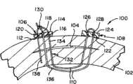
图1为本发明组织修复组件的示例性实施例的剖视图,该组件植入身体组织;Figure 1 is a cross-sectional view of an exemplary embodiment of a tissue repair assembly of the present invention implanted in body tissue;
图2A为本发明组织修复组件的示例性实施例的侧正视图,该组件设置在本发明的递送装置上;Figure 2A is a side elevational view of an exemplary embodiment of a tissue repair assembly of the present invention disposed on a delivery device of the present invention;
图2B和图2C分别为图2A中所示递送工具末端部分的侧正视图和俯视图;2B and 2C are side elevational and top views, respectively, of the end portion of the delivery tool shown in FIG. 2A;
图3A-3F为根据本发明用于修复组织缺陷的方法的示例性实施例的剖视图;3A-3F are cross-sectional views of exemplary embodiments of methods for repairing tissue defects according to the present invention;
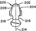
图4A-4C为本发明固定构件的示例性实施例的各自的俯视图、端视图和侧正视图,该固定构件具有三个用于接纳缝合线的贯穿开口;4A-4C are respective top, end, and side elevation views of an exemplary embodiment of a fixation member of the present invention having three through openings for receiving sutures;
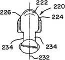
图5A-5C为本发明固定构件的另一个实施例的俯视图、端视图和侧正视图,该固定构件具有两个用于接纳缝合线的贯穿开口;5A-5C are top, end, and side elevation views of another embodiment of a fixation member of the present invention having two through openings for receiving sutures;
图6为本发明组织修复组件的透视图,该组件采用了图4A-4C和图5A-5C中的固定构件;Figure 6 is a perspective view of a tissue repair assembly of the present invention employing the fixation members of Figures 4A-4C and Figures 5A-5C;
图7为本发明固定构件的可供选择实施例的侧正视图,该固定构件具有三个用于接纳缝合线的贯穿开口;Figure 7 is a side elevational view of an alternative embodiment of a fixation member of the present invention having three through openings for receiving sutures;
图8为本发明固定构件的可供选择实施例的侧正视图,该固定构件具有两个用于接纳缝合线的贯穿开口;Figure 8 is a side elevational view of an alternative embodiment of a fixation member of the present invention having two through openings for receiving suture;
图9为本发明固定构件的另一实施例的侧正视图,该固定构件具有一个用于接纳缝合线的贯穿开口;Figure 9 is a side elevational view of another embodiment of the fixation member of the present invention having a through opening for receiving suture;
图10为沿图6中线10-10截取的剖视图;Figure 10 is a cross-sectional view taken along line 10-10 in Figure 6;
图11A-11F为本发明组织修复组件的其他实施例的俯视剖视图。11A-11F are top cross-sectional views of other embodiments of the tissue repair assembly of the present invention.
具体实施方式Detailed ways
本发明的设备和方法使得外科医生能够采用由连续缝合线段互连的两个固定构件一致地和牢靠地修复组织撕裂和分离。使用本发明的设备进行外科手术时,外科医生无需打任何缝合线结,尤其适用于进行关节镜式修复或内窥镜式修复。采用本发明进行的修复不会沿着互连固定构件的缝合线留下线结、缝合线接头或其他可能的应力点,并且可再现地将任何线结设置为远离特别易受术后损伤影响的组织区域,例如关节连接的组织表面。应当理解,本文所公开的具体设备和方法为示例性的而非限制本发明,例如本文示出的用于修复软组织(诸如膝半月板)的物质中损伤的实施例,可等同地施加以用于修复另一类软组织中的局部或完全撕裂,或用于修复一类组织与另一类组织的局部或完全分离(例如肌腱或韧带与骨的分离)。The devices and methods of the present invention enable a surgeon to consistently and securely repair tissue tears and separations using two fixation members interconnected by a continuous length of suture. When the device of the present invention is used for surgical operations, the surgeon does not need to tie any suture thread knots, and is especially suitable for arthroscopic or endoscopic repairs. Repairs using the present invention leave no knots, suture joints, or other potential stress points along the sutures interconnecting the fixation components, and reproducibly locate any knots away from the sutures that are particularly susceptible to postoperative damage tissue regions, such as articulated tissue surfaces. It should be understood that the specific devices and methods disclosed herein are exemplary and not limiting of the invention, for example the embodiments shown herein for repairing damage in a substance of soft tissue such as the knee meniscus are equally applicable to To repair a partial or complete tear in another type of soft tissue, or to repair a partial or complete separation of one type of tissue from another (eg, separation of tendons or ligaments from bone).
更具体地参见附图。图1示意性地示出了本发明组织修复组件100的示例性实施例的剖视图,该组件植入身体组织102,以用于修复组织102中的缺陷104。在一个示例性实施例中,组织102为膝中的半月板,缺陷104为半月板撕裂。在另一个实施例中,组织102为另一类身体组织。在另一个实施例中,缺陷104为两种不同类型身体组织之间的分离。See the attached drawings for more particularity. 1 schematically illustrates a cross-sectional view of an exemplary embodiment of a
修复组件100包括第一固定构件106、第二固定构件108、以及与第一固定构件106和第二固定构件108互连并且贯穿其中的连续挠性元件110。挠性元件110可包括适用于植入并且用于进行外科手术修复的任何类型的挠性元件,以下简称“缝合线”。缝合线110可为任何类型的缝合线,包括使用诸如丝绸的天然材料以及诸如聚对苯二甲酸乙二醇酯(PET)或其他聚酯材料的合成材料制成的缝合线。缝合线110可为可生物吸收的、部分可生物吸收的或不能被吸收的,并且可具有圆形横截面或其他横截面。在一个实施例中,缝合线110为部分可生物吸收的,其包含作为不能被吸收的组分的聚乙烯和作为可生物吸收的组分的聚二氧杂环己酮。The
第一固定构件106包括第一组织接触表面112、第一背表面114、以及第一组织接触表面112与第一背表面114之间的第一贯穿开口116、第二贯穿开口118和第三贯穿开口120。第二固定构件108包括第二组织接触表面122、第二背表面124、以及各自的组织接触表面122与背表面124之间的各自的第一贯穿开口126和第二贯穿开口128。在实施例中,各自的贯穿开口中的一个或多个适于缝合线110可滑动地穿过其中。在另一实施例中,各穿过第一固定构件106和第二固定构件108的相邻开口之间的各自的组织接触表面和背表面被倒圆,以优化缝合线110穿过各自的开口或在其间的可滑动性。在一个实施例中,开口中的每一个的横截面为圆形。在另一个实施例中,开口中的一个或多个在横向于连接一个或多个开口的线的方向上是细长的,其中相邻开口穿过各自的固定构件。The
缝合线110具有与第一固定构件106的背表面114相邻的滑动锁定结120。缝合线具有从滑动锁定结130延伸的连续套环部分132,套环部分132包括第一股缝合线134和第二股缝合线136。第一股缝合线134从滑动锁定结130延伸,朝向并穿过第一固定构件106中的各自的第一开口116,从各自的背表面114延伸至各自的组织接触表面112,朝向并穿过第二固定构件108中的各自的第一开口126,从各自的组织接触表面122延伸至各自的背表面124。继续从第二固定构件108的背表面124开始,第一股缝合线134与连续套环132中的第二股缝合线136是连续的,返回穿过各自的第二开口128,从背表面124延伸至第二固定构件108的组织接触表面122,朝向并穿过第一固定构件106中的各自的第二开口118到达滑动锁定结130,从而形成套环132。在实施例中,套环132设置为可滑动地穿过第一固定构件106和第二固定构件108中的每一个的各自的第一开口和第二开口中的每一个。The
在实施例中,第二股缝合线136固定连接到滑动锁定结130,第一股缝合线134可滑动地延伸穿过滑动锁定结130,到达张力调整股138并且与其是连续的,该张力调整股从滑动锁定结130延伸,朝向并穿过第三开口140,从各自的背面114延伸至第一固定构件106的组织接触面112。相对于第一固定构件106对张力调整股138施加的张力能够有效地将缝合线从套环132滑动地拉伸穿过第一固定构件中的各自的第一开口、滑动锁定结130和第三开口120,从而在传递的张力进一步将第二股缝合线136的一部分滑动地拉伸穿过第二固定构件108中的各自的第二开口128和第一开口126时缩短套环132。在实施例中,缩短套环132能够施加封闭组织102中的缺陷104的压缩力。应当注意的是,为了在图1中进行示意性的说明,示出的多种缝合线股134、136和138彼此横向分离地穿过组织102,但在使用组织修复组件100进行实际的组织修复中,多种缝合线股134、136和138沿着彼此相邻的基本上共用的通道穿过组织102。In an embodiment, the second strand of
图2A示意性地示出了组织修复组件100的示例性实施例的侧视图,其中组件设置在本发明的递送装置150上,递送装置150具有远端152和近端154。递送装置150包括从近端柄部158向远侧延伸的大致管状的远端递送构件156。图2B和图2C示出了各自的侧视图和俯视图中递送构件156的末端部分的详细视图,其中组织修复组件100设置在该递送构件上。FIG. 2A schematically illustrates a side view of an exemplary embodiment of a
第一固定构件106和第二固定构件108以及两者间延伸的缝合线110的至少一部分沿着递送构件156可滑动地保留,并且至少部分在该递送构件中。递送装置150也包括至少一个调配杆160,其在递送构件156中可向远侧滑动,以用于从递送构件156中向远侧按顺序排出第一固定构件106和第二固定构件108。柄部158包括至少一个可手动操纵的扳机162,其可操纵以用于向远侧滑动至少一个调配杆160中的一个。在一个实施例中,如图2A所示,递送构件156具有沿其长度的弯曲部164。在另一个实施例(未示出)中,递送构件156在柄部158和远端152之间基本上是直的。
在实施例中,第一固定构件106和第二固定构件108中的每一个可滑动地保留在递送构件156中的纵向狭槽166中,狭槽166从远端152朝柄部158向近侧延伸,并且具有用于可滑动地保留第一固定构件106和第二固定构件108的相对纵向边缘168。如图所示,调配杆160起初抵靠在递送构件156远端处腔体外部的第二固定构件108的下方,杆160滑动穿过腔体。调配好第一固定构件106后,接合第二扳机163,这使得第二调配杆161向远侧移动,并且将第二固定构件108沿着狭槽推入腔体内的启动位置(起初由第一固定构件106占据的位置)中,并且在扳机162接合后随时由杆160进行调配。如图所示,递送构件156在远侧终止于组织刺穿末端170中。作为另外一种选择,递送构件156在远侧终止于钝形顶端中。在实施例中,第一固定构件106和第二固定构件108中的每一个沿着呈现各自的固定构件最小截面的取向保留在递送构件156上,以用于连同递送构件156插入或穿过组织。In an embodiment, each of the
图2A中所示弹性管172设置在递送构件156周围。优选地,弹性管172由具有回弹力的透明有机硅材料制成。为了清楚起见,图2B和图2C中省去了管172。弹性管沿着递送构件的一部分设置在递送构件156周围,包围沿着第一固定构件106和第二固定构件108的递送构件156以及两者间缝合线的至少一部分的位置。弹性管172和固定构件106、108与保留在其中的缝合线之间的摩擦力将第一固定构件106和第二固定构件108在各自的固定构件递送到组织之前沿着递送构件156保留在预定的纵向位置处。相似地,弹性管172通过沿着递送构件保持缝合线为组织修复组件100提供缝合线管理。弹性管172的远端174在调配第一固定构件106和/或第二固定构件108中的任一者或两者之前对递送构件156插入组织中提供软性深度阻挡件。
图3A-3F示出了根据本发明用于修复组织缺陷的方法的示例性实施例。首先参见图3A,其上保留有组织修复组件100的递送构件156已穿过具有第一组织表面182和第二组织表面184的受损伤的身体组织180,到达第二组织表面184处的第一位置186,其中第一固定构件106已从递送构件156的远端滑动地排出,从而将第一固定构件106定位成靠近第一位置186。受损伤的身体组织180包括组织缺陷188。在实施例中,第一位置186由外科医生选定,以使得完成的修复对缺陷188施加压缩。在实施例中,组织缺陷188为半月板撕裂,并且压缩能够有效地封闭裂口。应当注意的是,为了在图3A至图3F中进行示意性的说明,如上文图1中也注明的那样,从各个固定构件延伸的多种缝合线股彼此横向分离地穿过第一组织表面182与第二组织表面184之间的组织180,但在实际组织修复过程中,多种缝合线股沿着与彼此相邻的基本上共用的通道穿过组织102。3A-3F illustrate an exemplary embodiment of a method for repairing a tissue defect according to the present invention. Referring first to FIG. 3A , the
作为另外一种选择,第一固定构件106可从递送构件156中排出,其中递送构件在受损伤的身体组织180的物质内,或在另一个身体组织的表面内或与该表面相邻。根据组织缺陷188的性质和位置,外科医生可以选择将递送构件156传递至第一位置186,直接穿过组织缺陷188、与组织缺陷188相邻或穿过组织的另一个区域,其中所调配的组织修复组件100能够有效地对整个组织缺陷188施加压缩。Alternatively,
现在参见图3B,递送构件156已从受损伤的身体组织180中退回,从而使第一固定构件106靠近第一位置186。虽然第一固定构件106可滑动地保留在递送构件156上,但却呈现出用于刺穿组织的最小截面。使用时,第一固定构件106会摆动,以使得各自的组织接触表面112在第一位置186处抵靠第二组织表面184,从而呈现出第一固定构件106的最大截面,以阻止从受损组织180中退出。Referring now to FIG. 3B , the
现在参见图3C,其上仍保留有第二固定构件108的递送构件156已第二次穿过受损伤的身体组织180,到达第二组织表面184处的第二位置190,其中第二固定构件108已从递送构件156的远端滑动地排出,从而将第二固定构件定位成靠近第二位置190。外科医生选择第二位置190和递送构件156穿过组织的通道的标准与用于选择第一位置186和穿过组织的相关通道的标准相同。优选地,第一位置186和第二位置190中的每一个都由外科医生选定,以使得完成的修复对组织缺陷188施加压缩。第二固定构件108可从递送构件156中排出,该递送构件在受损伤的身体组织188的物质内,或在另一个身体组织的表面内或与该表面相邻。Referring now to FIG. 3C , the
参见图3D,递送构件156已从受损伤的身体组织188中退回,从而使第二固定构件108靠近第二位置,并且使包括第一股缝合线134和第二股缝合线136的缝合线套环132的一部分定位成与第一组织表面182的横跨的部分192相邻。虽然第二固定构件108可滑动地保留在递送构件156上,但却呈现出用于刺穿组织的最小截面。从递送构件156排出时,作为对施加到第一股缝合线134和第二股缝合线136中的一个或两个上的张力的响应,第二固定构件108会摆动,以使得各自的组织接触表面122在第二位置190处抵靠第二组织表面184,从而呈现出第二固定构件108的最大截面,以阻止从受损组织180中退出。Referring to FIG. 3D , the
现在参见图3E,张力调整股138已相对于第一固定构件106拉紧,从而缩短缝合线套环132并且对组织缺陷188施加压缩力。如图所示,组织缺陷188为半月板撕裂,并且压缩力能够有效地封闭裂口。与第一组织表面182的横跨的部分192相邻的缝合线套环132的部分在拉紧后仍保持基本上在第一组织表面182上。优选地,拉紧使得具有套环132的缝合线局部压缩第一组织表面182,从而无缝合线暴露在第一组织表面182的其余部位上方,同时充分拉紧具有套环132的缝合线可嵌入第一组织表面182下的受损组织180,从而无缝合线暴露在第一组织表面182的其余部位上方。Referring now to FIG. 3E , tensioning
现在参见图3F,张力调整股138已在第一组织表面182处或在其下方被修整,从而无任何张力调整股138从第一组织表面182凸出。如图所示,受损组织180为膝半月板,组织缺陷为半月板撕裂,第一组织表面182为半月板的关节连接表面,第二组织表面184为半月板的周边边缘,第一固定构件106和第二固定构件108均调配在半月板周边被膜中。在其他实施例中,使用两个或更多个本发明的组织修复组件来修复组织缺陷,或修复组织中的物理地相邻的缺陷。Referring now to FIG. 3F , tension-adjusting
外科医生对第一固定构件106和第二固定构件108的各自的第一位置和第二位置的确定取决于多种因素,包括但不限于具有缺陷的组织的类型、缺陷的性质和程度、缺陷在组织中的位置、以及缺陷与外科手术部位附近可能存在的其他组织和其他缺陷的接近程度。第一固定构件和第二固定构件的各自的第一位置和第二位置可在受损组织的单个连续表面上。作为另外一种选择,第一位置和第二位置可位于沿着组织表面的组织缺陷的相对侧。第一位置和第二位置可在相对的组织表面上,组织缺陷位于两者间。第一位置和第二位置可在不同的组织上。The surgeon's determination of the respective first and second positions of the
图4A-4C示意性地示出了本发明的三开口固定构件200的示例性实施例的各自的俯视图、端视图和侧视图。在实施例中,三开口固定构件200为上文所公开的组织修复组件100的第一固定构件106。三开口固定构件200包括具有各自的第一表面204、各自的第二表面206和三个贯穿开口的第一主体202,其中三个贯穿开口包括在各自的第一表面204与第二表面206之间贯穿主体202的第一开口208、第二开口210和第三开口212。在实施例中,三开口固定构件200为第一固定构件106,各自的第一表面204为组织接触表面112,各自的第二表面206为背表面114。三开口固定构件200相对于各自的第一表面204与第二表面206之间的平面214对称。作为另外一种选择,各自的第一表面204和第二表面206可相对于平面214对称。4A-4C schematically illustrate top, end and side views, respectively, of an exemplary embodiment of a three-opening
三个贯穿开口208、210、212中的每一个以及与其相邻或在两者间的各自的第一表面204和第二表面206中的一个或两个被平滑地倒圆,以优化穿过开口以及在其间的缝合线的可滑动性。三个贯穿开口208、210、212中的一个或多个在垂直于将一个或多个开口与相邻的三个贯穿开口中的一个互连的线的方向上是细长的。一个或多个开口的细长形状可增强穿过各自的开口的缝合线的可滑动性。第一主体202也包括在各自的第一表面204和第二表面206中的每一个上的纵向凹槽216。每一个凹槽216都能够与递送构件156中的纵向狭槽166的边缘168中的一个滑动接合,以将三开口固定构件200保留在递送构件156中。Each of the three through
图5A-5C示意性地示出了本发明的双开口固定构件220的另一个实施例的各自的俯视图、端视图和侧视图。在实施例中,双开口固定构件220为上文所公开的组织修复组件100的第二固定构件108。与三开口固定构件200的构造相似,双开口固定构件220包括具有各自的第一表面224、各自的第二表面226以及两个贯穿开口的第二主体222,其中两个贯穿开口包括在各自的第一表面224与第二表面226之间贯穿第二主体222的各自的第一开口228和第二开口230。双开口固定构件220为第二固定构件108,各自的第一表面224为组织接触表面122,各自的第二表面226为各自的背表面124。双开口固定构件220相对于各自的第一表面224与第二表面226之间的各自的平面232对称。作为另外一种选择,各自的第一表面224和第二表面226相对于各自的平面232对称。Figures 5A-5C schematically illustrate top, end and side views, respectively, of another embodiment of a dual
双开口固定构件中的第一开口228和第二开口230以及与其相邻和在两者间的各自的第一表面224和第二表面226中的一个或两个被平滑地倒圆,以优化穿过开口以及在其间的缝合线的可滑动性。两个贯穿开口228、230中的一个或两个可在垂直于互连两个贯穿开口228、230的线的方向上是细长的,以增强穿过各自的开口的缝合线的可滑动性。第二主体222也包括在各自的第一表面224和第二表面226中的每一个上的各自的纵向凹槽234。每一个各自的凹槽234都能够与递送构件156中的纵向狭槽166的边缘168中的一个滑动接合,以将双开口固定构件220保留在递送构件156中。One or both of the
三开口固定构件200和双开口固定构件220可由任何生物相容性材料制成,并且可具有彼此相同或不同的组合物。在一个实施例中,固定构件200、220中的至少一个是不能被吸收的。在另一个实施例中,固定构件200、220中的至少一个由聚醚醚酮(PEEK)聚合物制成。在另一个实施例中,固定构件200、220中的至少一个是可生物吸收的。The triple-
图6示意性地示出了包括三开口固定构件200和双开口固定构件220的本发明组织修复组件250的示例性实施例的透视图。该组织修复组件具有与上文所公开的组织修复组件100相同的构造,其中缝合线110包括滑动锁定结130、第一股缝合线134、第二股缝合线136和张力调整股138,第一股缝合线134和第二股缝合线136包括缝合线套环132。FIG. 6 schematically illustrates a perspective view of an exemplary embodiment of a
缝合线110的接合部分在沿着缝合线110的位置(下文中称为“柱子”252)处滑动地穿过滑动锁定结130设置,大体上与第一固定构件200的各自的第二表面206相邻,位于第一开口208与第三开口212之间,柱子252包括沿着缝合线110在第一股缝合线134与张力调整股136之间的可滑动过渡部分。相对于三开口固定构件200拉紧张力调整股138以缩短套环132时,滑动锁定结130将柱子252锁定在其中,从而基本上防止套环132再伸长。滑动锁定结在外科手术领域是熟知的。滑动锁定结为拢帆索滑动结,这是外科手术领域以及诸如航海等其他领域已知的滑动锁定结类型。优选地,它还包括止索结254,以稳固从滑动锁定结130延伸的缝合线引线256。作为另外一种选择,止索结254可包括单8字结。The engagement portion of the
三开口固定构件200和双开口固定构件220优选地各由PEEK制成,缝合线110是包含超高分子量的聚乙烯(UHMWPE)和聚二氧杂环己酮(PDS)的部分可生物吸收的高强度缝合线。更优选地,UHMWPE和PDS缝合线由Depuy Mitek(Raynham,Massachusetts)经销的OrthocordTM缝合线。The three-opened
图7至图9示意性地示出了可包括本发明组织修复组件的多种可供选择的实施例的俯视图。图7示出了三开口固定构件260的另一个实施例的俯视图,其与图4A-4C和图6的固定构件200相似,不同的是,在图7示出的三开口固定构件260中,穿过各自的第一表面270与第二表面272之间的各自的主体268的三个开口262、264、266中的每一个都是圆形横截面。相似地,图8示出了双开口固定构件274的另一个实施例的俯视图,其与图5A-5C和图6的固定构件220相似,不同的是,在图8示出的双开口固定构件274中,穿过各自的第一表面282与第二表面284之间的各自的主体280的两个开口276、278中的每一个都是圆形横截面。7-9 schematically illustrate top views of various alternative embodiments that may include tissue repair assemblies of the present invention. FIG. 7 shows a top view of another embodiment of a three-opening fixing member 260, which is similar to the fixing
图9示意性地示出了本发明的单开口固定构件286的实施例。单开口固定构件286与双开口固定构件274和三开口固定构件260相似,但其只有穿过各自的第一表面292与第二表面294之间的各自的主体290的单开口288。结合包括三开口固定构件200和双开口固定构件220的组织修复组件250,在另一个实施例中,双开口固定构件220替换为单开口固定构件286,并且在三开口固定构件200与单开口固定构件286之间延伸的缝合线套环设置为穿过单个开口288。Figure 9 schematically illustrates an embodiment of a single
在另一个实施例中,除了用于在组织修复组件的构造中设置缝合线的贯穿开口外,包括本发明组织修复组件的固定构件还包括一个或多个开口。在另一个实施例中,基本上从三开口固定构件延伸的缝合线套环包括两个或更多个沿其设置的固定构件,穿过其中的每一个设置缝合线套环。In another embodiment, a fixation member comprising a tissue repair assembly of the present invention includes one or more openings in addition to through openings for placement of sutures in the configuration of the tissue repair assembly. In another embodiment, the suture loop extending substantially from the three-opened fixation member includes two or more fixation members disposed therealong, each of which has a suture loop disposed therethrough.
在本发明的组织固定组件中,缝合线基本上仅在一个纵向穿过与固定构件相关的止滑元件(限制元件),其中三股缝合线从固定构件延伸。限制元件可为缝合线在优选的纵向可穿过而限制在相对方向上穿过的任何类型的限制元件。在多个实施例中,限制元件为滑动锁定缝合线结。在另一个实施例中,限制元件包括在固定构件中的一个或多个开口,其中固定构件能够使具有优选滑动方向的有倒钩的缝合线穿过一个或多个开口。在另一个实施例中,限制元件为穿过或围绕固定构件本身的单向通道。In the tissue fixation assembly of the present invention, the suture passes substantially only in one longitudinal direction through the non-slip element (restricting element) associated with the fixation member, wherein three strands of suture extend from the fixation member. The restricting element may be any type of restricting element through which the suture is passable in a preferred longitudinal direction while restricting passage in the opposite direction. In various embodiments, the restraining element is a slide lock suture knot. In another embodiment, the restraining element comprises one or more openings in the fixation member, wherein the fixation member is capable of passing a barbed suture having a preferred sliding direction through the one or more openings. In another embodiment, the restricting element is a one-way channel through or around the fixation member itself.
图10示意性地示出了图6的组织修复组件250的一部分的横截面侧视图,图中示出了三开口固定构件200和穿过其设置的缝合线110的一部分的横截面图,其中滑动锁定结130顶靠第二表面206。穿过三开口固定构件200的三个开口208、210、212的内表面以及在其间的各自的第一表面204和第二表面206的一部分被倒圆,以分别优化缝合线110穿过其中和沿着其的滑动。10 schematically illustrates a cross-sectional side view of a portion of the
本发明的组织修复组件可构造成多种构型,包括任何尺寸和比例的适于修复具体组织缺陷的固定构件、选择所用缝合线的尺寸和类型、以及相对于固定构件的路线中的变型形式。继而可根据缝合线的路线选择用于构造本发明组织修复组件的固定构件中所需的贯穿开口数。图11A-11F示意性地示出了本发明组织修复组件的多种可供选择的实施例,其构型与上文所示实施例参照两个固定构件之间的缝合线路线以及穿过各自的固定构件的开口数中的一者或两者有所不同。应当注意,在不脱离本发明目的或范围的情况下,穿过本文所公开的固定构件中的任何者的开口总数可超过具体缝合线路线所需的开口数。The tissue repair assemblies of the present invention can be configured in a variety of configurations, including fixation members of any size and proportion suitable for repairing a particular tissue defect, selection of the size and type of sutures used, and variations in routing relative to the fixation members . The desired number of through openings in the fixation member used to construct the tissue repair assembly of the present invention can then be selected based on the routing of the suture. Figures 11A-11F schematically illustrate various alternative embodiments of the tissue repair assembly of the present invention, configured in the same manner as the embodiments shown above with reference to the routing of sutures between the two fixation members and through the respective One or both of the number of openings of the fixing member is different. It should be noted that the total number of openings through any of the fixation members disclosed herein may exceed the number of openings required for a particular suture route without departing from the purpose or scope of the present invention.
图11A示出了包括第一固定构件302和第二固定构件304的组织修复组件300的第一个可供选择的实施例。图11A示出的组织修复组件300也包括一段缝合线306和限制元件308。限制元件308是由缝合线306形成的滑动锁定结。该段缝合线306还包括与第二股缝合线312为连续的第一股缝合线310,第一股缝合线310和第二股缝合线312一起包括将第一固定构件302连接到第二固定构件304上的缝合线套环314。第二股缝合线312基本上固定地连接到限制构件308。第二股缝合线312穿过限制构件308延伸并且与由上文所公开的止索结318端接的缝合线引线316是连续的。第一股缝合线310按路线滑动地穿过限制构件308并且与张力调整股320是连续的。在本文所公开的多个实施例中,缝合线按路线穿过一个或多个穿过多种固定构件的开口。缝合线通常按路线滑动地穿过一个或多个开口,以确保平稳操作组件,以用于将各自的固定构件调配在组织中并且使缝合线滑动地穿过组件,以接近组织缺陷。FIG. 11A shows a first alternative embodiment of a tissue repair assembly 300 including a first fixation member 302 and a second fixation member 304 . The tissue repair assembly 300 shown in FIG. 11A also includes a length of suture 306 and a restraining
图11A至图11F中所示的多种可供选择的实施例包括一段缝合线306及其元件,但它们在各自的第一固定构件与第二固定构件周围和之间的路线有差别。如图11A所示的组织修复组件300的第一个可供选择的实施例,第一固定构件302包括穿过其中的第一开口322、第二开口324和第三开口326。第二固定构件304包括穿过其中的两个开口328、330。缝合线套环314按路线穿过第二固定构件304中的两个开口328、330中的每一个。第一股缝合线310按路线穿过第一固定构件302中的第一开口322,到达限制元件308。第二股缝合线312按路线穿过第一固定构件302中的第三开口326,到达限制元件308。张力调整股320按路线从限制元件308开始并且穿过第一固定构件302中的第二开口324。相对于第一固定构件302施加到张力调整股320上的张力能够有效地牵拉缝合线穿过限制元件308,从而减小套环314的尺寸。组织修复组件300与上文所公开的组织修复组件100、250相似,不同的是,在图11A的实施例中,张力调整股320按路线穿过各自的固定构件302的中心开口,与上文所公开的组织修复组件100、250的穿过路线设置相反。The various alternative embodiments shown in FIGS. 11A-11F include a length of suture 306 and its elements, but they route differently around and between the respective first and second fixation members. As shown in a first alternative embodiment of a tissue repair assembly 300 in FIG. 11A , the first fixation member 302 includes a first opening 322 , a second opening 324 , and a third opening 326 therethrough. The second fixation member 304 includes two openings 328, 330 therethrough. A
图11B示出了组织修复组件332的第二个可供选择的实施例,其包括图11A的实施例的第一固定构件302和第二固定构件304,但不同的是围绕和穿过第一固定构件302的缝合线路线以及限制元件308的构造不同。在图11B的组织修复组件332的实施例中,限制元件308为通过缝合线引线316附连到第一固定构件302上的滑动锁定缝合线结,其中该缝合线引线按路线穿过第一固定构件302中的第三开口326并且通过止索结318固定。第一股缝合线310和第二股缝合线312中的每一个按路线穿过第一固定构件302中的第一开口322和第二开口324中的一个。此外,在图11B的实施例中,张力调整股320的路线是围绕第一固定构件302,与图11A的组织修复组件300的第一个可供选择实施例所示的穿过第一固定构件302中的开口的路线相反。FIG. 11B shows a second alternative embodiment of a tissue repair assembly 332 that includes the first fixation member 302 and the second fixation member 304 of the embodiment of FIG. The suture routing of the fixation member 302 and the configuration of the restraining
图11C示出了组织修复组件334的第三个可供选择的实施例。图11C的组织修复组件334包括第一固定构件336,其具有穿过其中的第一开口338和第二开口340。组织修复组件334也包括第二固定构件342,其具有穿过其中的单个开口344。缝合线套环314按路线穿过第二固定构件342中的单个开口344,第一股缝合线310和第二股缝合线312中的每一个按路线穿过第一固定构件336中的第一开口338和第二开口340中的一个。如图11B的实施例所示的缝合线路线,张力调整股320的路线是围绕第一固定构件336。A third alternative embodiment of a
图11D示出了组织修复组件346的第四个可供选择的实施例。图11D中所示的组织修复组件346与图11C中所示的组织修复组件334相似,不同的是,在图11D所示的实施例中,张力调整股320的路线是从限制元件314开始,穿过第一固定构件336中的第二开口340。此外,第一股缝合线310和第二股缝合线312中的一个按路线穿过第一固定构件336中的第一开口338,第一股缝合线310和第二股缝合线312中的另一个按路线围绕在第一固定构件336周围。A fourth alternative embodiment of a
图11E示出了组织修复组件348的第五个可供选择的实施例,其包括第一固定构件350和第二固定构件352,该固定构件各具有穿过其中的单个各自的开口354、356。在该实施例中,缝合线套环320按路线穿过第二固定构件352中的单个开口356。第一股缝合线310和第二股缝合线312中的一个按路线穿过第一固定构件350中的单个开口354,缝合线的第一股缝合线310和第二股缝合线312中的另一个按路线围绕在第一固定构件350周围。此外,张力调整股320按路线围绕在第一固定构件350周围。FIG. 11E shows a fifth alternative embodiment of a
图11F示出了组织修复组件358的第六个可供选择的实施例,其包括第一固定构件360和第二固定构件362,该固定构件各具有穿过其中的两个各自的开口364、366、368、370。缝合线套环314按路线穿过第二固定构件362中的两个开口368、370中的每一个,第一股缝合线310和第二股缝合线312中的每一个按路线直接到达限制元件308,该限制元件设置为与第一固定构件360相邻,在第一固定构件360与第二固定构件362之间。限制元件308为通过缝合线引线316附连到第一固定构件360上的滑动锁定结,该缝合线引线按路线穿过第一固定构件360中的两个各自的开口364、366中的一个366,并且通过止索结318固定。张力调整股320按路线穿过第一固定构件360中的两个各自的开口364、366中的另一个364。FIG. 11F shows a sixth alternative embodiment of a
应当注意,在本文所公开的实施例中的任何者中,各自的第二固定构件的实施例中的任何者都可与各自的第一固定构件、相关限制元件和缝合线路线实施例中的任何者相结合,从而得到本发明目的和范围内的附加的实施例。It should be noted that in any of the embodiments disclosed herein, any of the respective second fixation member embodiments can be combined with any of the respective first fixation member, associated restraint element and suture route embodiments. Any combination to obtain additional embodiments within the purpose and scope of the present invention.
本发明的组织修复组件和方法具有若干优点。使用本发明组织修复组件的半月板修复手术可提供完美的组织修复,其中膝半月板关节连接表面(面向股骨的表面)上只留有缝合线,没有硬体或结,因而利于康复并且将患者在术后弯曲膝关节时接触半月板的关节连接软骨损伤的可能性降至最低。另外有利地,可相对于受损组织和相关组织缺陷以任何取向进行修复。本发明的组织修复组件为外科医生提供附加的灵活性,因为组织修复组件不包括任何限制两个组织固定构件的相对位置的固定缝合线长度。例如,用本发明组织修复组件进行的修复不会限制两个固定构件之间的最小距离。重要的是,使用本发明的组织修复组件,可从半月板的关节连接侧进行整个半月板修复,这种方法将对外围组织的手术创伤降至最低程度。The tissue repair assemblies and methods of the present invention have several advantages. Meniscus repair surgery using the tissue repair assembly of the present invention provides flawless tissue repair in which only sutures are left on the articulating surface of the knee meniscus (the surface facing the femur) without hard bodies or knots, thereby facilitating recovery and bringing the patient The possibility of damage to the articular cartilage that touches the meniscus during postoperative flexion of the knee is minimized. Also advantageously, repair can be performed in any orientation relative to the damaged tissue and associated tissue defects. The tissue repair assembly of the present invention provides additional flexibility to the surgeon because the tissue repair assembly does not include any fixed suture lengths that limit the relative position of the two tissue fixation members. For example, repairs performed with the tissue repair assemblies of the present invention do not limit the minimum distance between two fixation members. Importantly, using the tissue repair assembly of the present invention, the entire meniscus repair can be performed from the articulating side of the meniscus in a manner that minimizes surgical trauma to surrounding tissues.
另一个优点是,通过两股不间断的连续的缝合线为使用本发明组织修复组件进行的修复提供了强度和稳定性,该缝合线股在第一固定构件和第二固定构件之间不包括任何沿着其的接头、结或止动件。还有利地,相对于跨过锚定位置的单个打结的或接合的缝合线段,提供完全跨过锚定位置的两条缝合线可在所修复组织上提供出色的力分布。Another advantage is that strength and stability are provided for repairs using the tissue repair assembly of the present invention by two strands of uninterrupted continuous suture that do not include any suture strands between the first and second fixation members. Any joints, knots or stops along it. Also advantageously, providing two sutures completely across the anchor site provides superior force distribution on the repaired tissue relative to a single knotted or joined suture segment across the anchor site.
本发明的组织修复组件的应用也十分广泛,包括适用于半月板修复、局部肩袖撕裂的修复、以及任何其他两个组织或组织内的损伤需要用外科手术进行修复的软组织修复。此外,通过在骨中预先钻出一个或多个洞以用于插入递送构件,组织修复组件可用于将软组织锚定到骨上。The application of the tissue repair assembly of the present invention is also very wide, including meniscus repair, partial rotator cuff tear repair, and any other soft tissue repair where two tissues or injuries within tissues need to be repaired by surgery. Additionally, the tissue repair assembly can be used to anchor soft tissue to bone by pre-drilling one or more holes in the bone for insertion of the delivery member.
尽管本发明尤其是结合具体优选的实施例加以示出和描述,但本领域的技术人员应当理解,在不脱离由所附权利要求书限定的本发明的精神和范围的前提下,可以在形式和细节方面进行多种变更。While the present invention has been shown and described with particular reference to specific preferred embodiments, it should be understood by those skilled in the art that it may be made in the form of Variations in details and details.
Claims (47)
Priority Applications (1)
| Application Number | Priority Date | Filing Date | Title |
|---|---|---|---|
| CN202210310636.0ACN114931408A (en) | 2009-07-24 | 2010-07-23 | Apparatus and method for repairing tissue |
Applications Claiming Priority (2)
| Application Number | Priority Date | Filing Date | Title |
|---|---|---|---|
| US22839609P | 2009-07-24 | 2009-07-24 | |
| US61/228396 | 2009-07-24 |
Related Child Applications (1)
| Application Number | Title | Priority Date | Filing Date |
|---|---|---|---|
| CN202210310636.0ADivisionCN114931408A (en) | 2009-07-24 | 2010-07-23 | Apparatus and method for repairing tissue |
Publications (1)
| Publication Number | Publication Date |
|---|---|
| CN101961256Atrue CN101961256A (en) | 2011-02-02 |
Family
ID=43016114
Family Applications (2)
| Application Number | Title | Priority Date | Filing Date |
|---|---|---|---|
| CN2010102365878APendingCN101961256A (en) | 2009-07-24 | 2010-07-23 | Devices and methods for repairing tissue |
| CN202210310636.0APendingCN114931408A (en) | 2009-07-24 | 2010-07-23 | Apparatus and method for repairing tissue |
Family Applications After (1)
| Application Number | Title | Priority Date | Filing Date |
|---|---|---|---|
| CN202210310636.0APendingCN114931408A (en) | 2009-07-24 | 2010-07-23 | Apparatus and method for repairing tissue |
Country Status (6)
| Country | Link |
|---|---|
| US (5) | US8790369B2 (en) |
| EP (1) | EP2277456B1 (en) |
| JP (1) | JP5769938B2 (en) |
| CN (2) | CN101961256A (en) |
| AU (2) | AU2010202954A1 (en) |
| CA (1) | CA2710909A1 (en) |
Cited By (40)
| Publication number | Priority date | Publication date | Assignee | Title |
|---|---|---|---|---|
| CN103619266A (en)* | 2011-05-06 | 2014-03-05 | 赛特里克斯整形公司 | Meniscus repair |
| CN103892878A (en)* | 2012-12-27 | 2014-07-02 | 德普伊米特克有限责任公司 | Surgical constructs and methods for securing tissue |
| CN104274220A (en)* | 2014-10-22 | 2015-01-14 | 陕西福泰医疗科技有限公司 | Fastening device for memory alloy suture line |
| CN104394778A (en)* | 2012-03-09 | 2015-03-04 | 史密夫和内修有限公司 | Suture-based knotless repair |
| TWI481380B (en)* | 2011-12-15 | 2015-04-21 | Pergolas Medical Technology | Minimally invasive tendon suturing surgical kit |
| US9211119B2 (en) | 2007-07-03 | 2015-12-15 | Ceterix Orthopaedics, Inc. | Suture passers and methods of passing suture |
| US9247935B2 (en) | 2013-09-23 | 2016-02-02 | Ceterix Orthopaedics, Inc. | Arthroscopic knot pusher and suture cutter |
| US9247934B2 (en) | 2011-05-06 | 2016-02-02 | Ceterix Orthopaedics, Inc. | Suture passer devices and methods |
| US9314234B2 (en) | 2007-07-03 | 2016-04-19 | Ceterix Orthopaedics, Inc. | Pre-tied surgical knots for use with suture passers |
| CN105979883A (en)* | 2013-07-30 | 2016-09-28 | 阿库洛医药有限公司 | Ligation devices, kits and methods |
| US9492162B2 (en) | 2013-12-16 | 2016-11-15 | Ceterix Orthopaedics, Inc. | Automatically reloading suture passer devices and methods |
| CN106794015A (en)* | 2014-07-18 | 2017-05-31 | 伊西康公司 | The machinery retraction by tying realization for reducing Pulmonary volume |
| US9757116B2 (en) | 2012-05-07 | 2017-09-12 | Medos International Sárl | Systems, devices, and methods for securing tissue |
| US9763655B2 (en) | 2012-09-20 | 2017-09-19 | Medos International Sarl | Systems, devices, and methods for securing tissue using hard anchors |
| US9795373B2 (en) | 2012-05-07 | 2017-10-24 | Medos International Sàrl | Systems, devices, and methods for securing tissue using a suture having one or more protrusions |
| CN107361806A (en)* | 2016-05-13 | 2017-11-21 | 美多斯国际有限公司 | For delivering the devices, systems, and methods of tissue fixation device |
| US9833229B2 (en) | 2010-12-23 | 2017-12-05 | Medos International Sàrl | Adjustable anchor systems and methods |
| CN107440752A (en)* | 2016-04-20 | 2017-12-08 | 美多斯国际有限公司 | Meniscal repair devices, systems and methods |
| US9848868B2 (en) | 2011-01-10 | 2017-12-26 | Ceterix Orthopaedics, Inc. | Suture methods for forming locking loops stitches |
| US9872678B2 (en) | 2012-03-30 | 2018-01-23 | Medos International Sarl | Surgical filament assemblies |
| US9895145B2 (en) | 2010-11-23 | 2018-02-20 | Medos International Sàrl | Surgical filament snare assemblies |
| US9913638B2 (en) | 2011-01-10 | 2018-03-13 | Ceterix Orthopaedics, Inc. | Transosteal anchoring methods for tissue repair |
| CN108201455A (en)* | 2018-01-23 | 2018-06-26 | 上海利格泰生物科技有限公司 | Suture hot plate unit and threading system |
| US10004492B2 (en) | 2009-11-09 | 2018-06-26 | Ceterix Orthopaedics, Inc. | Suture passer with radiused upper jaw |
| CN108472133A (en)* | 2015-10-21 | 2018-08-31 | 核心医疗股份公司 | Medical implant and method for heart valve repair |
| CN109350151A (en)* | 2018-11-29 | 2019-02-19 | 北京天星博迈迪医疗器械有限公司 | A kind of meniscus stitching unstrument |
| CN109419541A (en)* | 2017-08-31 | 2019-03-05 | 美多斯国际有限公司 | Device and method for tissue repair |
| US10226245B2 (en) | 2015-07-21 | 2019-03-12 | Ceterix Orthopaedics, Inc. | Automatically reloading suture passer devices that prevent entanglement |
| CN109561894A (en)* | 2016-08-16 | 2019-04-02 | 康曼德公司 | For suture to be fixed to the device of the holdfast body of suture holdfast |
| US10271833B2 (en) | 2012-05-07 | 2019-04-30 | Medos International Sàrl | Systems, devices, and methods for securing tissue using snare assemblies and soft anchors |
| US10292695B2 (en) | 2010-11-23 | 2019-05-21 | Medos International Sàrl | Surgical filament snare assemblies |
| US10405853B2 (en) | 2015-10-02 | 2019-09-10 | Ceterix Orthpaedics, Inc. | Knot tying accessory |
| US10441273B2 (en) | 2007-07-03 | 2019-10-15 | Ceterix Orthopaedics, Inc. | Pre-tied surgical knots for use with suture passers |
| US10524778B2 (en) | 2011-09-28 | 2020-01-07 | Ceterix Orthopaedics | Suture passers adapted for use in constrained regions |
| US10537321B2 (en) | 2014-04-08 | 2020-01-21 | Ceterix Orthopaedics, Inc. | Suture passers adapted for use in constrained regions |
| US10631848B2 (en) | 2013-03-15 | 2020-04-28 | Medos International Sàrl | Surgical constructs with collapsing suture loop and methods for securing tissue |
| WO2022188376A1 (en)* | 2021-03-12 | 2022-09-15 | 杭州锐健马斯汀医疗器材有限公司 | Implant, implant forming method, and suture instrument |
| CN115778457A (en)* | 2022-11-10 | 2023-03-14 | 上海利格泰生物科技有限公司 | A bone implant, positioning sleeve, inserter and implantation system |
| US11744575B2 (en) | 2009-11-09 | 2023-09-05 | Ceterix Orthopaedics, Inc. | Suture passer devices and methods |
| CN119632735A (en)* | 2024-11-08 | 2025-03-18 | 常州市第一人民医院 | A meniscus implant |
Families Citing this family (71)
| Publication number | Priority date | Publication date | Assignee | Title |
|---|---|---|---|---|
| US7972337B2 (en) | 2005-12-28 | 2011-07-05 | Intrinsic Therapeutics, Inc. | Devices and methods for bone anchoring |
| EP1624832A4 (en)* | 1999-08-18 | 2008-12-24 | Intrinsic Therapeutics Inc | Devices and method for augmenting a vertebral disc nucleus |
| US7094258B2 (en)* | 1999-08-18 | 2006-08-22 | Intrinsic Therapeutics, Inc. | Methods of reinforcing an annulus fibrosis |
| US8323341B2 (en) | 2007-09-07 | 2012-12-04 | Intrinsic Therapeutics, Inc. | Impaction grafting for vertebral fusion |
| US7553329B2 (en)* | 1999-08-18 | 2009-06-30 | Intrinsic Therapeutics, Inc. | Stabilized intervertebral disc barrier |
| US7717961B2 (en)* | 1999-08-18 | 2010-05-18 | Intrinsic Therapeutics, Inc. | Apparatus delivery in an intervertebral disc |
| CA2425951C (en)* | 1999-08-18 | 2008-09-16 | Intrinsic Therapeutics, Inc. | Devices and method for nucleus pulposus augmentation and retention |
| US7998213B2 (en)* | 1999-08-18 | 2011-08-16 | Intrinsic Therapeutics, Inc. | Intervertebral disc herniation repair |
| US7722644B2 (en) | 2003-06-11 | 2010-05-25 | Medicine Lodge, Inc. | Compact line locks and methods |
| JP2007515988A (en)* | 2003-06-20 | 2007-06-21 | イントリンジック セラピューティックス インコーポレイテッド | Device and method for delivering an implant from an annular defect of an intervertebral disc |
| US8128640B2 (en) | 2005-02-07 | 2012-03-06 | Ivy Sports Medicine LLC | System and method for all-inside suture fixation for implant attachment and soft tissue repair |
| JP5030797B2 (en) | 2005-02-07 | 2012-09-19 | アイビー スポーツ メディシン、エルエルシー | System and method for fully internal suture fixation of implant placement and soft tissue repair |
| US20110196492A1 (en)* | 2007-09-07 | 2011-08-11 | Intrinsic Therapeutics, Inc. | Bone anchoring systems |
| US9717581B2 (en)* | 2009-02-05 | 2017-08-01 | Coloplast A/S | Incontinence treatment device including a system of anchors |
| US8864797B2 (en)* | 2009-07-02 | 2014-10-21 | Coorstek Medical Llc | Systems and methods for intra-operative tension and fixation of zipknot ACL fixation |
| US10010439B2 (en)* | 2010-06-13 | 2018-07-03 | Synerz Medical, Inc. | Intragastric device for treating obesity |
| US8795334B2 (en) | 2011-01-28 | 2014-08-05 | Smith & Nephew, Inc. | Tissue repair |
| US8926661B2 (en)* | 2011-06-02 | 2015-01-06 | Smith & Nephew, Inc. | Surgical fastening |
| US9198648B2 (en) | 2011-06-20 | 2015-12-01 | Ethicon, Inc. | Method and device for approximating tissue |
| US10667895B2 (en)* | 2011-06-30 | 2020-06-02 | Boston Scientific Scimed, Inc. | Implants, tools, and methods for treatments of pelvic conditions |
| US9192368B2 (en) | 2011-08-04 | 2015-11-24 | Smith & Nephew, Inc. | Suspension device to anchor tissue graft |
| US9439644B2 (en) | 2011-12-20 | 2016-09-13 | Medos International Sàrl | Systems and methods for repairing tissue |
| US9517060B2 (en) | 2012-09-27 | 2016-12-13 | Ethicon, Inc. | Method and device for approximating tissue |
| US8986327B2 (en) | 2012-10-18 | 2015-03-24 | Smith & Nephew, Inc. | Flexible anchor delivery system |
| US10111651B2 (en) | 2012-11-02 | 2018-10-30 | Coloplast A/S | System and method of anchoring support material to tissue |
| US20140128913A1 (en)* | 2012-11-02 | 2014-05-08 | Coloplast A/S | Surgical system including an anchor insertable into a cannula of an introducer |
| US9795426B2 (en)* | 2013-03-07 | 2017-10-24 | DePuy Synthes Products, Inc. | Implants |
| US10052094B2 (en) | 2013-03-11 | 2018-08-21 | Medos International Sàrl | Implant having adjustable filament coils |
| US9974643B2 (en) | 2013-03-11 | 2018-05-22 | Medos International Sàrl | Implant having adjustable filament coils |
| US12064329B2 (en)* | 2013-03-15 | 2024-08-20 | Boston Scientific Scimed, Inc. | Surgical implant system and method |
| AU2014228420B2 (en) | 2013-03-15 | 2018-11-08 | Smith & Nephew, Inc. | Surgical fastening |
| WO2014190080A1 (en)* | 2013-05-21 | 2014-11-27 | Ams Research Corporation | Surgical implant system and method |
| US9757113B2 (en) | 2013-07-31 | 2017-09-12 | Medos International Sàrl | Adjustable graft fixation device |
| US9480546B2 (en) | 2013-08-05 | 2016-11-01 | Coloplast A/S | Hysteropexy mesh apparatuses and methods |
| US10405968B2 (en) | 2013-12-11 | 2019-09-10 | Medos International Sarl | Implant having filament limbs of an adjustable loop disposed in a shuttle suture |
| US20150282803A1 (en)* | 2014-04-02 | 2015-10-08 | Vishal M. Mehta | Surgical device for repairing tissue |
| WO2015193317A1 (en)* | 2014-06-20 | 2015-12-23 | Endo Tools Therapeutics S.A. | Assembly for securing gastrointestinal tissue folds |
| US9687223B2 (en) | 2014-12-04 | 2017-06-27 | Coloplast A/S | Tissue anchor system |
| US20170027617A1 (en)* | 2015-07-31 | 2017-02-02 | Intrepid Orthopedics | Odontoid bullet |
| US10251639B1 (en) | 2015-11-20 | 2019-04-09 | Ronald Yamada | Meniscus repair system |
| EP3383281B1 (en) | 2015-12-04 | 2024-01-24 | Crossroads Extremity Systems, LLC | Devices for anchoring tissue |
| US10932769B2 (en) | 2016-05-26 | 2021-03-02 | Ivy Sports Medicine, Llc | System and method for all-inside suture fixation for implant attachment and soft tissue repair |
| WO2018085663A1 (en)* | 2016-11-03 | 2018-05-11 | Smith & Nephew, Inc. | Tissue repair assembly and system with soft anchoring implant |
| US10758224B2 (en) | 2017-03-27 | 2020-09-01 | Trimed, Incorporated | System and method controlling a relationship between first and second bodies on a person |
| US10603028B2 (en) | 2017-06-14 | 2020-03-31 | Medos International Sarl | Finger traps for collapsible suture loops |
| US10675015B2 (en)* | 2017-07-12 | 2020-06-09 | Ethicon, Inc. | Systems, devices and methods for delivering transfascial suture implants for securing surgical mesh to tissue |
| WO2020069486A1 (en)* | 2018-09-28 | 2020-04-02 | Conmed Corporation | System for repairing soft tissue tears |
| CA3121264A1 (en)* | 2018-12-05 | 2020-06-11 | Paragon 28, Inc. | Soft tissue implant systems, instruments and related methods |
| EP3905967A4 (en)* | 2019-01-04 | 2022-10-05 | The Texas A&M University System | Approximating anchor device |
| FR3094625A1 (en)* | 2019-04-02 | 2020-10-09 | Jean-Luc Raynier | Device for reinserting soft tissue to a bone support |
| FR3095586B1 (en)* | 2019-05-05 | 2023-09-29 | Missana Marie Christine | BREAST IMPLANT WITH A FIXATION CLIP |
| CN111557701B (en)* | 2019-05-10 | 2024-09-20 | 华中科技大学同济医学院附属协和医院 | A meniscus repair suture puncture needle |
| US12295563B2 (en)* | 2019-10-09 | 2025-05-13 | Board Of Supervisors Of Louisiana State University And Agricultural And Mechanical College | Button for anchoring of multiple sutures |
| US12194575B2 (en) | 2020-01-13 | 2025-01-14 | Milwaukee Electric Tool Corporation | Portable battery pack-powered welder |
| USD980424S1 (en) | 2020-04-29 | 2023-03-07 | Coloplast A/S | Tissue anchor |
| US11944288B2 (en) | 2020-04-29 | 2024-04-02 | Coloplast A/S | Tissue anchor system including a fixation device and a delivery tool |
| JP7736699B2 (en) | 2020-04-30 | 2025-09-09 | アキュームド・エルエルシー | Friction-reduced knotless suture routing |
| KR102170400B1 (en)* | 2020-08-31 | 2020-10-27 | 정윤호 | Prostate enlargement treatment device |
| US12357443B2 (en)* | 2020-08-31 | 2025-07-15 | Cedars Health Inc. | Benign prostatic hyperplasia treatment device |
| US20220280148A1 (en)* | 2021-03-03 | 2022-09-08 | Carilion Clinic | Soft tissue fixation devices and methods |
| AU2022254721B2 (en)* | 2021-04-08 | 2024-12-12 | Integrity Orthopaedics, Inc. | Cartridge device for suture anchor and suture management during implantation of a micro suture anchor array |
| CA3214365A1 (en)* | 2021-04-08 | 2022-10-13 | Integrity Orthopaedics, Inc. | Tensionable and lockable micro suture anchors and anchor arrays for anatomical attachment of soft tissue to bone |
| US11382611B1 (en)* | 2021-04-08 | 2022-07-12 | Integrity Orthopaedics, Inc. | Knotless micro-suture anchors and anchor arrays for anatomical attachment of soft tissue to bone |
| US11389154B1 (en)* | 2021-04-08 | 2022-07-19 | Integrity Orthopaedics, Inc. | Knotless micro suture anchor array for high density anatomical attachment of soft tissue to bone |
| US20220323198A1 (en)* | 2021-04-08 | 2022-10-13 | Integrity Orthopaedics, Inc. | Tensionable and lockable micro suture anchors and anchor arrays for anatomical attachment of soft tissue to bone |
| US11375992B1 (en)* | 2021-04-08 | 2022-07-05 | Integrity Orthopaedics, Inc. | Cartridge device for suture anchor and suture management during implantation of a micro suture anchor array |
| US11382613B1 (en)* | 2021-04-08 | 2022-07-12 | Integrity Orthopaedics, Inc. | Methods for transtendinous implantation of knotless micro suture anchors and anchor arrays |
| US11375995B1 (en)* | 2021-04-08 | 2022-07-05 | Integrity Orthopaedics, Inc. | Locking suture construct for tensioned suture to suture stitches in anchor arrays for attaching soft tissue to bone |
| US12226307B2 (en)* | 2021-04-08 | 2025-02-18 | Integrity Orthopaedics, Inc. | Individually lockable cinch loop micro suture anchor array for high density anatomical attachment of soft tissue to bone |
| US12433581B2 (en) | 2021-08-23 | 2025-10-07 | Arthrex, Inc. | Tensionable interconnected anchors with double punch inserter |
| US12426871B2 (en) | 2022-08-24 | 2025-09-30 | Globus Medical, Inc. | Systems, devices and methods for implanting suture buttons |
Citations (2)
| Publication number | Priority date | Publication date | Assignee | Title |
|---|---|---|---|---|
| US20050033363A1 (en)* | 1999-12-02 | 2005-02-10 | Ray Bojarski | Methods and devices for tissue repair |
| US20050251208A1 (en)* | 2004-05-07 | 2005-11-10 | Usgi Medical Inc. | Linear anchors for anchoring to tissue |
Family Cites Families (59)
| Publication number | Priority date | Publication date | Assignee | Title |
|---|---|---|---|---|
| US261501A (en)* | 1882-07-18 | Bag and sail tie | ||
| US233475A (en)* | 1880-10-19 | l vandermark | ||
| US4235238A (en)* | 1978-05-11 | 1980-11-25 | Olympus Optical Co., Ltd. | Apparatus for suturing coeliac tissues |
| US5085661A (en)* | 1990-10-29 | 1992-02-04 | Gerald Moss | Surgical fastener implantation device |
| CA2100532C (en)* | 1992-09-21 | 2004-04-20 | David T. Green | Device for applying a meniscal staple |
| US5693060A (en)* | 1992-11-17 | 1997-12-02 | Smith & Nephew, Inc. | Suture securing device and method |
| US5320633A (en)* | 1992-12-10 | 1994-06-14 | William C. Allen | Method and system for repairing a tear in the meniscus |
| US5467786A (en)* | 1992-12-10 | 1995-11-21 | William C. Allen | Method for repairing tears and incisions in soft tissue |
| US5464426A (en)* | 1993-05-14 | 1995-11-07 | Bonutti; Peter M. | Method of closing discontinuity in tissue |
| US5470337A (en)* | 1994-05-17 | 1995-11-28 | Moss; Gerald | Surgical fastener |
| US5601571A (en)* | 1994-05-17 | 1997-02-11 | Moss; Gerald | Surgical fastener implantation device |
| US5810848A (en)* | 1996-08-21 | 1998-09-22 | Hayhurst; John O. | Suturing system |
| US5709708A (en)* | 1997-01-31 | 1998-01-20 | Thal; Raymond | Captured-loop knotless suture anchor assembly |
| US6126578A (en)* | 1998-01-02 | 2000-10-03 | Lapointe; Brian | Jumping device having a flexible tether and method of using the jumping device |
| US6045551A (en)* | 1998-02-06 | 2000-04-04 | Bonutti; Peter M. | Bone suture |
| US6143006A (en)* | 1998-04-18 | 2000-11-07 | Chan; Kwan-Ho | Apparatus and method for tying and tensioning knots |
| US6056320A (en)* | 1998-10-23 | 2000-05-02 | Chrysler Corporation | Energy absorbing occupant restraint system |
| US6306159B1 (en)* | 1998-12-23 | 2001-10-23 | Depuy Orthopaedics, Inc. | Meniscal repair device |
| US7226467B2 (en) | 1999-04-09 | 2007-06-05 | Evalve, Inc. | Fixation device delivery catheter, systems and methods of use |
| EP2221007B1 (en)* | 1999-12-02 | 2015-05-20 | Smith & Nephew, Inc. | Wound closure device |
| US7153312B1 (en)* | 1999-12-02 | 2006-12-26 | Smith & Nephew Inc. | Closure device and method for tissue repair |
| US6635073B2 (en)* | 2000-05-03 | 2003-10-21 | Peter M. Bonutti | Method of securing body tissue |
| US6500184B1 (en)* | 2001-01-31 | 2002-12-31 | Yung C. Chan | Suturing apparatus and method of suturing |
| FR2826253B1 (en)* | 2001-06-21 | 2004-03-12 | Sofradim Production | ASSEMBLY COMPRISING A FASTENING ATTACHMENT FOR MEDICAL USE AND A DEVICE FOR THE POSITIONING OF THIS ATTACHMENT |
| GB0116247D0 (en)* | 2001-07-04 | 2001-08-29 | Univ Loughborough | Surgical techniques and devices |
| US20050027307A1 (en)* | 2001-07-16 | 2005-02-03 | Schwartz Herbert Eugene | Unitary surgical device and method |
| US7235091B2 (en)* | 2002-06-20 | 2007-06-26 | Brian Thornes | Apparatus and method for fixation of ankle syndesmosis |
| US6767037B2 (en)* | 2001-09-27 | 2004-07-27 | Depuy Mitek, Inc. | Sliding and locking surgical knot |
| US7150750B2 (en)* | 2002-01-10 | 2006-12-19 | Boston Scientific Scimed, Inc. | Method and device for endoscopic suturing |
| US6972027B2 (en)* | 2002-06-26 | 2005-12-06 | Stryker Endoscopy | Soft tissue repair system |
| US7594923B2 (en)* | 2003-06-11 | 2009-09-29 | Medicine Lodge, Inc | Line lock suture attachment systems and methods |
| US7357810B2 (en)* | 2003-12-18 | 2008-04-15 | Ethicon, Inc. | High strength suture with absorbable core and suture anchor combination |
| US7390332B2 (en)* | 2004-02-24 | 2008-06-24 | Depuy Mitek, Inc. | Methods and devices for repairing tissue |
| US7455683B2 (en)* | 2004-02-26 | 2008-11-25 | Depuy Mitek, Inc. | Methods and devices for repairing triangular fibrocartilage complex tears |
| US8057511B2 (en)* | 2004-05-07 | 2011-11-15 | Usgi Medical, Inc. | Apparatus and methods for positioning and securing anchors |
| US8257394B2 (en)* | 2004-05-07 | 2012-09-04 | Usgi Medical, Inc. | Apparatus and methods for positioning and securing anchors |
| WO2005110244A1 (en) | 2004-05-07 | 2005-11-24 | Usgi Medical Inc. | Apparatus and methods for positioning and securing anchors |
| US7678135B2 (en)* | 2004-06-09 | 2010-03-16 | Usgi Medical, Inc. | Compressible tissue anchor assemblies |
| US9173647B2 (en) | 2004-10-26 | 2015-11-03 | P Tech, Llc | Tissue fixation system |
| US7905904B2 (en)* | 2006-02-03 | 2011-03-15 | Biomet Sports Medicine, Llc | Soft tissue repair device and associated methods |
| US7658751B2 (en)* | 2006-09-29 | 2010-02-09 | Biomet Sports Medicine, Llc | Method for implanting soft tissue |
| US7905903B2 (en)* | 2006-02-03 | 2011-03-15 | Biomet Sports Medicine, Llc | Method for tissue fixation |
| US7909851B2 (en)* | 2006-02-03 | 2011-03-22 | Biomet Sports Medicine, Llc | Soft tissue repair device and associated methods |
| US20060190042A1 (en)* | 2004-11-05 | 2006-08-24 | Arthrotek, Inc. | Tissue repair assembly |
| US7572275B2 (en)* | 2004-12-08 | 2009-08-11 | Stryker Endoscopy | System and method for anchoring suture to bone |
| US8128640B2 (en)* | 2005-02-07 | 2012-03-06 | Ivy Sports Medicine LLC | System and method for all-inside suture fixation for implant attachment and soft tissue repair |
| JP5030797B2 (en)* | 2005-02-07 | 2012-09-19 | アイビー スポーツ メディシン、エルエルシー | System and method for fully internal suture fixation of implant placement and soft tissue repair |
| US7981140B2 (en)* | 2005-03-30 | 2011-07-19 | Arthrex, Inc. | Knotless fixation of tissue to bone with suture chain |
| CA2605251C (en)* | 2005-04-20 | 2014-09-30 | Arthroscopic Innovations Llc | Suture fixation device and method for surgical repair |
| US8333777B2 (en)* | 2005-04-22 | 2012-12-18 | Benvenue Medical, Inc. | Catheter-based tissue remodeling devices and methods |
| US8795364B2 (en)* | 2005-05-06 | 2014-08-05 | Kensey Nash Corporation | System and devices for the repair of a vertebral disc defect |
| US20060287676A1 (en)* | 2005-06-15 | 2006-12-21 | Rita Prajapati | Method of intra-operative coating therapeutic agents onto sutures, composite sutures and methods of use |
| US20070083236A1 (en)* | 2005-06-24 | 2007-04-12 | Smith & Nephew, Inc. | Methods and devices for tissue repair |
| US20060293709A1 (en)* | 2005-06-24 | 2006-12-28 | Bojarski Raymond A | Tissue repair device |
| US7815659B2 (en)* | 2005-11-15 | 2010-10-19 | Ethicon Endo-Surgery, Inc. | Suture anchor applicator |
| US20080033487A1 (en) | 2006-08-07 | 2008-02-07 | Bioduct, Llc | Medical device for repair of tissue and method for implantation and fixation |
| EP2098172B1 (en)* | 2008-03-04 | 2017-02-22 | Arthrex, Inc. | System for meniscal repair using suture implant cinch construct |
| US20090229623A1 (en)* | 2008-03-13 | 2009-09-17 | Raymond Fricker | Nail Grooming Appartus |
| US9445806B2 (en)* | 2009-02-06 | 2016-09-20 | Karl Storz Gmbh & Co. Kg | Suture holder delivery system |
- 2009
- 2009-10-30USUS12/609,448patent/US8790369B2/enactiveActive
- 2010
- 2010-07-13AUAU2010202954Apatent/AU2010202954A1/ennot_activeAbandoned
- 2010-07-22CACA2710909Apatent/CA2710909A1/ennot_activeAbandoned
- 2010-07-23CNCN2010102365878Apatent/CN101961256A/enactivePending
- 2010-07-23CNCN202210310636.0Apatent/CN114931408A/enactivePending
- 2010-07-23JPJP2010165578Apatent/JP5769938B2/enactiveActive
- 2010-07-26EPEP10251323.1Apatent/EP2277456B1/enactiveActive
- 2014
- 2014-06-17USUS14/306,299patent/US9421012B2/enactiveActive
- 2016
- 2016-01-20AUAU2016200321Apatent/AU2016200321B2/enactiveActive
- 2016-08-15USUS15/236,824patent/US10149675B2/enactiveActive
- 2018
- 2018-12-10USUS16/214,236patent/US11071537B2/enactiveActive
- 2021
- 2021-07-26USUS17/384,899patent/US20210346009A1/ennot_activeAbandoned
Patent Citations (2)
| Publication number | Priority date | Publication date | Assignee | Title |
|---|---|---|---|---|
| US20050033363A1 (en)* | 1999-12-02 | 2005-02-10 | Ray Bojarski | Methods and devices for tissue repair |
| US20050251208A1 (en)* | 2004-05-07 | 2005-11-10 | Usgi Medical Inc. | Linear anchors for anchoring to tissue |
Cited By (78)
| Publication number | Priority date | Publication date | Assignee | Title |
|---|---|---|---|---|
| US9211119B2 (en) | 2007-07-03 | 2015-12-15 | Ceterix Orthopaedics, Inc. | Suture passers and methods of passing suture |
| US9314234B2 (en) | 2007-07-03 | 2016-04-19 | Ceterix Orthopaedics, Inc. | Pre-tied surgical knots for use with suture passers |
| US10441273B2 (en) | 2007-07-03 | 2019-10-15 | Ceterix Orthopaedics, Inc. | Pre-tied surgical knots for use with suture passers |
| US10004492B2 (en) | 2009-11-09 | 2018-06-26 | Ceterix Orthopaedics, Inc. | Suture passer with radiused upper jaw |
| US11744575B2 (en) | 2009-11-09 | 2023-09-05 | Ceterix Orthopaedics, Inc. | Suture passer devices and methods |
| US10912549B2 (en) | 2010-11-23 | 2021-02-09 | Medos International Sàrl | Surgical filament snare assemblies |
| US12329371B2 (en) | 2010-11-23 | 2025-06-17 | Medos International Sarl | Surgical filament snare assemblies |
| US12357294B2 (en) | 2010-11-23 | 2025-07-15 | Medos International Sàrl | Surgical filament snare assemblies |
| US10292695B2 (en) | 2010-11-23 | 2019-05-21 | Medos International Sàrl | Surgical filament snare assemblies |
| US11039827B2 (en) | 2010-11-23 | 2021-06-22 | Medos International Sàrl | Surgical filament snare assemblies |
| US9895145B2 (en) | 2010-11-23 | 2018-02-20 | Medos International Sàrl | Surgical filament snare assemblies |
| US10835231B2 (en) | 2010-12-23 | 2020-11-17 | Medos International Sàrl | Adjustable anchor systems and methods |
| US9833229B2 (en) | 2010-12-23 | 2017-12-05 | Medos International Sàrl | Adjustable anchor systems and methods |
| US9913638B2 (en) | 2011-01-10 | 2018-03-13 | Ceterix Orthopaedics, Inc. | Transosteal anchoring methods for tissue repair |
| US10987095B2 (en) | 2011-01-10 | 2021-04-27 | Ceterix Orthopaedics, Inc. | Suture methods for forming locking loops stitches |
| US10561410B2 (en) | 2011-01-10 | 2020-02-18 | Ceterix Orthopaedics, Inc. | Transosteal anchoring methods for tissue repair |
| US9848868B2 (en) | 2011-01-10 | 2017-12-26 | Ceterix Orthopaedics, Inc. | Suture methods for forming locking loops stitches |
| US9247934B2 (en) | 2011-05-06 | 2016-02-02 | Ceterix Orthopaedics, Inc. | Suture passer devices and methods |
| US10758222B2 (en) | 2011-05-06 | 2020-09-01 | Ceterix Orthopaedics, Inc. | Meniscus repair |
| US9700299B2 (en) | 2011-05-06 | 2017-07-11 | Ceterix Orthopaedics, Inc. | Suture passer devices and methods |
| US9861354B2 (en) | 2011-05-06 | 2018-01-09 | Ceterix Orthopaedics, Inc. | Meniscus repair |
| CN103619266B (en)* | 2011-05-06 | 2017-02-08 | 赛特里克斯整形公司 | Meniscus repair |
| US10188382B2 (en) | 2011-05-06 | 2019-01-29 | Ceterix Orthopaedics, Inc. | Suture passer devices and methods |
| CN103619266A (en)* | 2011-05-06 | 2014-03-05 | 赛特里克斯整形公司 | Meniscus repair |
| US10524778B2 (en) | 2011-09-28 | 2020-01-07 | Ceterix Orthopaedics | Suture passers adapted for use in constrained regions |
| TWI481380B (en)* | 2011-12-15 | 2015-04-21 | Pergolas Medical Technology | Minimally invasive tendon suturing surgical kit |
| CN104394778A (en)* | 2012-03-09 | 2015-03-04 | 史密夫和内修有限公司 | Suture-based knotless repair |
| US10751041B2 (en) | 2012-03-30 | 2020-08-25 | Medos International Sarl | Surgical filament assemblies |
| US9872678B2 (en) | 2012-03-30 | 2018-01-23 | Medos International Sarl | Surgical filament assemblies |
| US11771414B2 (en) | 2012-03-30 | 2023-10-03 | Medos International Sarl | Surgical filament assemblies |
| US10271833B2 (en) | 2012-05-07 | 2019-04-30 | Medos International Sàrl | Systems, devices, and methods for securing tissue using snare assemblies and soft anchors |
| US9795373B2 (en) | 2012-05-07 | 2017-10-24 | Medos International Sàrl | Systems, devices, and methods for securing tissue using a suture having one or more protrusions |
| US11272915B2 (en) | 2012-05-07 | 2022-03-15 | Medos International Sarl | Systems, devices, and methods for securing tissue using snare assemblies and soft anchors |
| US9757116B2 (en) | 2012-05-07 | 2017-09-12 | Medos International Sárl | Systems, devices, and methods for securing tissue |
| US11564676B2 (en) | 2012-05-07 | 2023-01-31 | Medos International Sarl | Systems, devices, and methods for securing tissue |
| US10524777B2 (en) | 2012-05-07 | 2020-01-07 | Medos International Sàrl | Systems, devices, and methods for securing tissue |
| US12336700B2 (en) | 2012-05-07 | 2025-06-24 | Medos International Sarl | Systems, devices, and methods for securing tissue |
| US12310573B2 (en) | 2012-05-07 | 2025-05-27 | Medos International Sàrl | Systems, devices, and methods for securing tissue using snare assemblies and soft anchors |
| US9763655B2 (en) | 2012-09-20 | 2017-09-19 | Medos International Sarl | Systems, devices, and methods for securing tissue using hard anchors |
| US11672523B2 (en) | 2012-09-20 | 2023-06-13 | Medos International Sarl | Systems, devices, and methods for securing tissue using hard anchors |
| US10695047B2 (en) | 2012-09-20 | 2020-06-30 | Medos International Sarl | Systems, devices, and methods for securing tissue using hard anchors |
| US12369902B2 (en) | 2012-09-20 | 2025-07-29 | Medos International Sàrl | Systems, devices, and methods for securing tissue using hard anchors |
| US11369361B2 (en) | 2012-12-27 | 2022-06-28 | Medos International Sarl | Surgical constructs and methods for securing tissue |
| CN103892878A (en)* | 2012-12-27 | 2014-07-02 | 德普伊米特克有限责任公司 | Surgical constructs and methods for securing tissue |
| US10258321B2 (en) | 2012-12-27 | 2019-04-16 | Medos International Sàrl | Surgical constructs and methods for securing tissue |
| CN103892878B (en)* | 2012-12-27 | 2018-10-26 | 德普伊米特克有限责任公司 | Surgery tectosome and method for fixing organization |
| US11672522B2 (en) | 2013-03-15 | 2023-06-13 | Medos International Sarl | Surgical constructs with collapsing suture loop and methods for securing tissue |
| US10631848B2 (en) | 2013-03-15 | 2020-04-28 | Medos International Sàrl | Surgical constructs with collapsing suture loop and methods for securing tissue |
| US12402874B2 (en) | 2013-03-15 | 2025-09-02 | Medos International Sàrl | Surgical constructs with collapsing suture loop and methods for securing tissue |
| CN105979883A (en)* | 2013-07-30 | 2016-09-28 | 阿库洛医药有限公司 | Ligation devices, kits and methods |
| CN105979883B (en)* | 2013-07-30 | 2018-10-09 | 阿库洛医药有限公司 | Ligation devices, kits and methods |
| US10143464B2 (en) | 2013-09-23 | 2018-12-04 | Ceterix Orthopaedics, Inc. | Arthroscopic knot pusher and suture cutter |
| US9332980B2 (en) | 2013-09-23 | 2016-05-10 | Ceterix Orthopaedics, Inc. | Arthroscopic knot pusher and suture cutter |
| US9247935B2 (en) | 2013-09-23 | 2016-02-02 | Ceterix Orthopaedics, Inc. | Arthroscopic knot pusher and suture cutter |
| US10820899B2 (en) | 2013-09-23 | 2020-11-03 | Ceterix Orthopaedics, Inc. | Arthroscopic knot pusher and suture cutter |
| US10524779B2 (en) | 2013-12-16 | 2020-01-07 | Ceterix Orthopaedics, Inc. | Automatically reloading suture passer devices and methods |
| US9492162B2 (en) | 2013-12-16 | 2016-11-15 | Ceterix Orthopaedics, Inc. | Automatically reloading suture passer devices and methods |
| US10537321B2 (en) | 2014-04-08 | 2020-01-21 | Ceterix Orthopaedics, Inc. | Suture passers adapted for use in constrained regions |
| CN106794015A (en)* | 2014-07-18 | 2017-05-31 | 伊西康公司 | The machinery retraction by tying realization for reducing Pulmonary volume |
| CN104274220A (en)* | 2014-10-22 | 2015-01-14 | 陕西福泰医疗科技有限公司 | Fastening device for memory alloy suture line |
| US10226245B2 (en) | 2015-07-21 | 2019-03-12 | Ceterix Orthopaedics, Inc. | Automatically reloading suture passer devices that prevent entanglement |
| US10806442B2 (en) | 2015-07-21 | 2020-10-20 | Ceterix Orthopaedics, Inc. | Automatically reloading suture passer devices that prevent entanglement |
| US10405853B2 (en) | 2015-10-02 | 2019-09-10 | Ceterix Orthpaedics, Inc. | Knot tying accessory |
| CN112618108A (en)* | 2015-10-21 | 2021-04-09 | 核心医疗股份公司 | Medical implant and method for heart valve repair |
| CN108472133A (en)* | 2015-10-21 | 2018-08-31 | 核心医疗股份公司 | Medical implant and method for heart valve repair |
| CN107440752A (en)* | 2016-04-20 | 2017-12-08 | 美多斯国际有限公司 | Meniscal repair devices, systems and methods |
| CN107361806B (en)* | 2016-05-13 | 2022-07-05 | 美多斯国际有限公司 | Devices, systems, and methods for delivering tissue fixation devices |
| CN107361806A (en)* | 2016-05-13 | 2017-11-21 | 美多斯国际有限公司 | For delivering the devices, systems, and methods of tissue fixation device |
| US11045304B2 (en) | 2016-05-13 | 2021-06-29 | Medos International Sarl | Device, system, and method for delivery of a tissue fixation device |
| CN109561894A (en)* | 2016-08-16 | 2019-04-02 | 康曼德公司 | For suture to be fixed to the device of the holdfast body of suture holdfast |
| CN109419541A (en)* | 2017-08-31 | 2019-03-05 | 美多斯国际有限公司 | Device and method for tissue repair |
| CN108201455B (en)* | 2018-01-23 | 2023-07-18 | 上海利格泰生物科技股份有限公司 | Suture orifice mechanism and threading system |
| CN108201455A (en)* | 2018-01-23 | 2018-06-26 | 上海利格泰生物科技有限公司 | Suture hot plate unit and threading system |
| CN109350151B (en)* | 2018-11-29 | 2024-05-17 | 北京天星医疗股份有限公司 | A meniscus suture device |
| CN109350151A (en)* | 2018-11-29 | 2019-02-19 | 北京天星博迈迪医疗器械有限公司 | A kind of meniscus stitching unstrument |
| WO2022188376A1 (en)* | 2021-03-12 | 2022-09-15 | 杭州锐健马斯汀医疗器材有限公司 | Implant, implant forming method, and suture instrument |
| CN115778457A (en)* | 2022-11-10 | 2023-03-14 | 上海利格泰生物科技有限公司 | A bone implant, positioning sleeve, inserter and implantation system |
| CN119632735A (en)* | 2024-11-08 | 2025-03-18 | 常州市第一人民医院 | A meniscus implant |
Also Published As
| Publication number | Publication date |
|---|---|
| AU2016200321B2 (en) | 2017-08-31 |
| CN114931408A (en) | 2022-08-23 |
| US9421012B2 (en) | 2016-08-23 |
| EP2277456A1 (en) | 2011-01-26 |
| US11071537B2 (en) | 2021-07-27 |
| AU2016200321A1 (en) | 2016-02-11 |
| US20210346009A1 (en) | 2021-11-11 |
| CA2710909A1 (en) | 2011-01-24 |
| US20110022061A1 (en) | 2011-01-27 |
| US20160345957A1 (en) | 2016-12-01 |
| US20190105030A1 (en) | 2019-04-11 |
| EP2277456B1 (en) | 2018-04-18 |
| JP5769938B2 (en) | 2015-08-26 |
| US10149675B2 (en) | 2018-12-11 |
| US20140296913A1 (en) | 2014-10-02 |
| AU2010202954A1 (en) | 2011-02-10 |
| US20160206305A9 (en) | 2016-07-21 |
| JP2011025036A (en) | 2011-02-10 |
| US8790369B2 (en) | 2014-07-29 |
Similar Documents
| Publication | Publication Date | Title |
|---|---|---|
| US20210346009A1 (en) | Apparatus and method for repairing tissue | |
| US20210401432A1 (en) | Methods and devices for repairing and anchoring damaged tissue | |
| US12016545B2 (en) | Methods and devices for repairing meniscal tissue | |
| US20240090891A1 (en) | Filamentary Fixation Device | |
| CA3010005C (en) | Suture tape construct for providing anchor with non-sliding suture tape | |
| KR20190031274A (en) | A device for suturing anchors to anchor bodies of suture anchors |
Legal Events
| Date | Code | Title | Description |
|---|---|---|---|
| C06 | Publication | ||
| PB01 | Publication | ||
| C10 | Entry into substantive examination | ||
| SE01 | Entry into force of request for substantive examination | ||
| RJ01 | Rejection of invention patent application after publication | Application publication date:20110202 | |
| RJ01 | Rejection of invention patent application after publication |