CN101958461B - Microwave antenna and outer cover thereof - Google Patents
Microwave antenna and outer cover thereofDownload PDFInfo
- Publication number
- CN101958461B CN101958461BCN2010102748771ACN201010274877ACN101958461BCN 101958461 BCN101958461 BCN 101958461BCN 2010102748771 ACN2010102748771 ACN 2010102748771ACN 201010274877 ACN201010274877 ACN 201010274877ACN 101958461 BCN101958461 BCN 101958461B
- Authority
- CN
- China
- Prior art keywords
- microwave antenna
- cover
- antenna
- outer cover
- reflection part
- Prior art date
- Legal status (The legal status is an assumption and is not a legal conclusion. Google has not performed a legal analysis and makes no representation as to the accuracy of the status listed.)
- Expired - Fee Related
Links
Images


Classifications
- H—ELECTRICITY
- H01—ELECTRIC ELEMENTS
- H01Q—ANTENNAS, i.e. RADIO AERIALS
- H01Q19/00—Combinations of primary active antenna elements and units with secondary devices, e.g. with quasi-optical devices, for giving the antenna a desired directional characteristic
- H01Q19/10—Combinations of primary active antenna elements and units with secondary devices, e.g. with quasi-optical devices, for giving the antenna a desired directional characteristic using reflecting surfaces
- H01Q19/18—Combinations of primary active antenna elements and units with secondary devices, e.g. with quasi-optical devices, for giving the antenna a desired directional characteristic using reflecting surfaces having two or more spaced reflecting surfaces
- H—ELECTRICITY
- H01—ELECTRIC ELEMENTS
- H01Q—ANTENNAS, i.e. RADIO AERIALS
- H01Q1/00—Details of, or arrangements associated with, antennas
- H01Q1/42—Housings not intimately mechanically associated with radiating elements, e.g. radome
- H—ELECTRICITY
- H01—ELECTRIC ELEMENTS
- H01Q—ANTENNAS, i.e. RADIO AERIALS
- H01Q19/00—Combinations of primary active antenna elements and units with secondary devices, e.g. with quasi-optical devices, for giving the antenna a desired directional characteristic
- H01Q19/10—Combinations of primary active antenna elements and units with secondary devices, e.g. with quasi-optical devices, for giving the antenna a desired directional characteristic using reflecting surfaces
- H01Q19/12—Combinations of primary active antenna elements and units with secondary devices, e.g. with quasi-optical devices, for giving the antenna a desired directional characteristic using reflecting surfaces wherein the surfaces are concave
- H01Q19/13—Combinations of primary active antenna elements and units with secondary devices, e.g. with quasi-optical devices, for giving the antenna a desired directional characteristic using reflecting surfaces wherein the surfaces are concave the primary radiating source being a single radiating element, e.g. a dipole, a slot, a waveguide termination
- H01Q19/134—Rear-feeds; Splash plate feeds
- H—ELECTRICITY
- H01—ELECTRIC ELEMENTS
- H01Q—ANTENNAS, i.e. RADIO AERIALS
- H01Q19/00—Combinations of primary active antenna elements and units with secondary devices, e.g. with quasi-optical devices, for giving the antenna a desired directional characteristic
- H01Q19/10—Combinations of primary active antenna elements and units with secondary devices, e.g. with quasi-optical devices, for giving the antenna a desired directional characteristic using reflecting surfaces
- H01Q19/18—Combinations of primary active antenna elements and units with secondary devices, e.g. with quasi-optical devices, for giving the antenna a desired directional characteristic using reflecting surfaces having two or more spaced reflecting surfaces
- H01Q19/19—Combinations of primary active antenna elements and units with secondary devices, e.g. with quasi-optical devices, for giving the antenna a desired directional characteristic using reflecting surfaces having two or more spaced reflecting surfaces comprising one main concave reflecting surface associated with an auxiliary reflecting surface
Landscapes
- Details Of Aerials (AREA)
Abstract
Translated fromChinese
Description
Translated fromChinese【技术领域】【Technical field】
本发明涉及通信天线领域,尤其涉及一种微波天线及其外罩。The invention relates to the field of communication antennas, in particular to a microwave antenna and its outer cover.
【背景技术】【Background technique】
随着微波通信需求的增长,由微波天线组成的点对点或点对多点的通信网络越来越密集,微波系统之间产生互相干扰的潜在风险越来越大。为此,各行政当局和网络运营商制定了严格的标准以限定微波天线的辐射方向图包络(Radiation Patterns Envelope,RPE),再根据不同的网络要求来选择满足不同标准等级的天线。在天线的电气性能指标中,辐射前后比(Front-to-BackRatio,F/B)尤为重要,是必须在天线的设计中着重考虑的。With the increasing demand for microwave communication, the point-to-point or point-to-multipoint communication network composed of microwave antennas is becoming more and more dense, and the potential risk of mutual interference between microwave systems is increasing. To this end, various administrative authorities and network operators have formulated strict standards to limit the Radiation Patterns Envelope (RPE) of microwave antennas, and then select antennas that meet different standard levels according to different network requirements. Among the electrical performance indicators of the antenna, the Front-to-Back Ratio (F/B) is particularly important and must be considered in the design of the antenna.
天线罩是微波天线系统中的重要组成部件,主要起两重作用:第一,保护天线免受灰尘、雨雪、冰冻等自然环境的影响;第二,减小天线系统的风力负荷以减轻天线安装系统的机械性能要求。因此天线罩的工程设计目标通常包括:The radome is an important component of the microwave antenna system. It mainly plays two roles: first, to protect the antenna from dust, rain, snow, freezing and other natural environments; second, to reduce the wind load of the antenna system to lighten the antenna. Mechanical performance requirements of the installation system. The engineering design goals for a radome therefore typically include:
1)在电气性能上,天线罩不能恶化天线的增益、回波损耗、RPE以及F/B等性能指标,最佳的设计目标是能改善天线的电气性能;1) In terms of electrical performance, the radome cannot deteriorate the antenna's performance indicators such as gain, return loss, RPE, and F/B. The best design goal is to improve the electrical performance of the antenna;
2)在机械性能上,天线罩需具有结构强度好、体积小、风荷小等特点;2) In terms of mechanical properties, the radome needs to have the characteristics of good structural strength, small size, and small wind load;
3)在成本方面,天线罩本身的成本以及配合到天线上的附加成本要低。3) In terms of cost, the cost of the radome itself and the additional cost matched to the antenna are lower.
天线罩对天线电气性能的影响主要体现在:The impact of the radome on the electrical performance of the antenna is mainly reflected in:
1)损失天线增益,这主要由天线罩引入的插入损耗导致,因此要求天线罩设计时不仅要选择低损耗的介质材料还要合理设计其厚度以达到最佳的透波性能;1) The loss of antenna gain is mainly caused by the insertion loss introduced by the radome. Therefore, it is required not only to choose a low-loss dielectric material but also to design its thickness reasonably to achieve the best wave transmission performance when designing the radome;
2)增加天线的回波损耗,即恶化天线的输入电压驻波比(VSWR),这主要是由天线罩导致的反射电磁波重新回到馈源所致;2) Increase the return loss of the antenna, that is, deteriorate the input voltage standing wave ratio (VSWR) of the antenna, which is mainly caused by the reflected electromagnetic wave caused by the radome returning to the feed source;
3)影响天线的RPE性能,这主要是由于天线罩使得天线口面电场的相位分布不再均匀,从而抬高了天线的近副瓣或者远副瓣电平;3) It affects the RPE performance of the antenna, mainly because the radome makes the phase distribution of the electric field on the surface of the antenna no longer uniform, thus raising the level of the near sidelobe or far sidelobe of the antenna;
4)恶化天线的F/B性能,这主要是由于天线罩扰乱了天线口面边缘的绕射场分布所致,甚至天线罩对绕射场起后向“引导”作用,从而提高了天线的后向辐射。4) Deteriorating the F/B performance of the antenna, which is mainly due to the fact that the radome disturbs the diffraction field distribution at the edge of the antenna mouth, and even the radome plays a role of "guiding" the diffraction field backwards, thereby improving the antenna's back radiation.
传统的微波天线所用的天线罩方案主要有三种结构形式(参阅图1所包括的a、b、c):平板形(a)、外凸形(b)以及内凹形(c),天线罩的材质一般选用质地均匀、介电常数稳定和损耗低的介质材料。传统天线罩方案均不能完全满足上述电气性能设计目标,抑或机械性能和成本无优势。平板形天线罩通常采用厚度约半个介质波长以获得较好的透波性能,从而减小天线罩对增益和VSWR的影响。但是平板形天线罩存在以下不足:The radome schemes used in traditional microwave antennas mainly have three structural forms (refer to a, b, and c included in Figure 1): flat plate (a), convex (b) and concave (c), radome The material of the material generally chooses a dielectric material with uniform texture, stable dielectric constant and low loss. None of the traditional radome solutions can fully meet the above electrical performance design goals, or have no advantages in mechanical performance and cost. Flat-shaped radome usually has a thickness of about half the wavelength of the medium to obtain better wave-transmitting performance, thereby reducing the influence of the radome on gain and VSWR. However, there are the following disadvantages in the flat radome:
1)频带宽度受限,因而不适用于宽频带天线系统;1) The frequency bandwidth is limited, so it is not suitable for broadband antenna systems;
2)由于天线罩边缘部分通常未经特殊赋形,因此对天线的RPE尤其是F/B有较大影响;2) Since the edge of the radome is usually not specially shaped, it has a great influence on the RPE of the antenna, especially the F/B;
3)平板形天线罩的机械强度较差。3) The mechanical strength of the flat radome is poor.
内凹形天线罩虽然可以通过一定的锥角设计以获得较宽的频带特性,但是往往未考虑到对RPE尤其是F/B性能的影响;另外,内凹形天线罩的机械强度和风荷性能不佳。Although the concave radome can be designed with a certain cone angle to obtain wider frequency band characteristics, the impact on RPE, especially F/B performance is often not considered; in addition, the mechanical strength and wind load performance of the concave radome bad.
外凸形天线罩可经一定的赋形设计获得较好的频带特性和F/B性能,而且机械强度和风荷性能亦较好,但是在对RPE性能的影响上,外凸形天线罩至多是不产生恶化,难起改善作用;另外,外凸形天线罩会增加天线的整体尺寸,从而增加包装和运输成本。The convex radome can obtain better frequency band characteristics and F/B performance through a certain shape design, and the mechanical strength and wind load performance are also better, but in terms of the impact on RPE performance, the convex radome is at most It is difficult to improve without deterioration; in addition, the convex radome will increase the overall size of the antenna, thereby increasing the packaging and transportation costs.
【发明内容】【Content of invention】
本发明的目的在于克服上述天线罩方案之不足,提供一种微波天线及其外罩,使外罩在微波天线中不仅具有较好的电气性能和机械性能,而且成本亦较低。The object of the present invention is to overcome the disadvantages of the above-mentioned radome solution, and provide a microwave antenna and its outer cover, so that the outer cover not only has better electrical and mechanical properties in the microwave antenna, but also has a lower cost.
为实现该目的,本发明采用如下技术方案:To achieve this goal, the present invention adopts following technical scheme:
本发明的微波天线外罩,用于遮罩微波天线,为旋转对称件,该外罩包括如下同心设置的多个部分:The microwave antenna cover of the present invention is used to cover the microwave antenna and is a rotationally symmetrical piece. The cover includes a plurality of concentrically arranged parts as follows:
补偿部分,位于外罩中部,用于补偿微波天线中由于馈源遮挡造成的天线口面中部电场分布的相位延迟;The compensation part, located in the middle of the outer cover, is used to compensate the phase delay of the electric field distribution in the middle of the antenna mouth surface caused by the shielding of the feed source in the microwave antenna;
主反射部分,位于补偿部分的外围,用于将来自微波天线馈源的电磁波反射到偏离馈源的特定方向上;The main reflection part, located on the periphery of the compensation part, is used to reflect the electromagnetic wave from the microwave antenna feed to a specific direction away from the feed;
辅反射部分,位于主反射部分的外围,用于对微波天线的边缘绕射电磁波进行聚束反射。The auxiliary reflection part is located on the periphery of the main reflection part, and is used for focusing and reflecting electromagnetic waves diffracted by the edge of the microwave antenna.
所述补偿部分朝外罩的遮罩侧方向内凹,呈高斯形、锥面形或球面形内凹状。The compensation part is concave toward the mask side of the outer cover, and is in a Gaussian, conical or spherical concave shape.
所述主反射部分朝外罩的遮罩侧方向内凹,呈斜锥面形内凹状。The main reflection part is concave toward the shield side of the outer cover, and is concave in the shape of an oblique cone.
所述辅反射部分朝外罩的外露侧方向外凸。The auxiliary reflective part protrudes outward toward the exposed side of the cover.
所述补偿部分的厚度小于主反射部分的厚度。The thickness of the compensation part is smaller than the thickness of the main reflection part.
所述主反射部分将电磁波反射到的特定方向被定义为对应天线整体辐射方向图中属于主瓣之外的区域。所述特定方向为天线整体辐射方向图中的零点角度位置或远旁瓣角度位置。The specific direction to which the main reflection part reflects the electromagnetic wave is defined as a region outside the main lobe in the overall radiation pattern of the corresponding antenna. The specific direction is the zero point angle position or the far side lobe angle position in the overall radiation pattern diagram of the antenna.
该外罩补偿部分的直径与该馈源的副反射面的直径相等。The diameter of the compensating part of the cover is equal to the diameter of the secondary reflection surface of the feed source.
本发明的微波天线,包括馈源、反射面以及前述的外罩,该反射面开口面设有向外的翻边;该外罩于紧邻其辅反射部分设有与所述翻边相配合的裙边;所述翻边与所述裙边相螺锁。The microwave antenna of the present invention includes a feed source, a reflective surface and the aforementioned outer cover, the opening of the reflective surface is provided with an outward flanging; the outer cover is provided with a skirt matched with the flanging adjacent to its auxiliary reflecting part ; The flange is screw-locked with the skirt.
所述翻边与所述裙边之间以装设在外罩遮罩侧的面上的限位卡箍件卡固并限位。Between the flange and the skirt is clamped and limited by a limiting clip installed on the surface of the cover side of the outer cover.
外罩于其外露侧紧贴所述裙边设有吸波材料,所述吸波材料为泡沫、海绵、橡胶中任意一种。The outer cover is provided with a wave-absorbing material close to the skirt on its exposed side, and the wave-absorbing material is any one of foam, sponge, and rubber.
与现有技术相比,本发明具有如下优点:Compared with prior art, the present invention has following advantage:
(1)在电气性能上,能显著提高微波天线的辐射F/B性能,能改善天线的口面电场分布的相位特性进而提高天线增益和口径效率,能改善RPE性能如副瓣电平,而对其它电气性能如输入电压驻波比、交叉极化鉴别率等影响较小;(1) In terms of electrical performance, it can significantly improve the radiation F/B performance of microwave antennas, improve the phase characteristics of the antenna’s orifice electric field distribution, and then improve antenna gain and aperture efficiency, and can improve RPE performance such as sidelobe levels, while Little impact on other electrical properties such as input voltage standing wave ratio, cross polarization discrimination rate, etc.;
(2)在机械性能上,外罩部分的拱形结构同时起加强筋的作用,因此天线罩整体的结构强度好,同时天线罩还具有体积小、重量轻、风荷小、外形美观等特点;(2) In terms of mechanical properties, the arched structure of the outer cover part also acts as a reinforcing rib, so the overall structural strength of the radome is good, and the radome also has the characteristics of small size, light weight, small wind load, and beautiful appearance;
(3)在成本方面,本发明所述的外罩部分可通过模具注塑一次成型从而加工成本低,同时天线罩整体的内凹形状也使与天线配合安装后的总体尺寸增加不多,因而附加的包装和运输成本较低。(3) In terms of cost, the outer cover part of the present invention can be molded by injection molding at one time so that the processing cost is low. At the same time, the overall concave shape of the radome also makes the overall size increase after it is installed with the antenna. Therefore, the additional Packaging and shipping costs are lower.
【附图说明】【Description of drawings】
图1是几种传统的微波天线罩与反射面安装后的剖面示意图,其中(a)为平板形天线罩,(b)为外凸形天线罩,(c)为内凹形天线罩。Figure 1 is a schematic cross-sectional view of several traditional microwave radomes after installation with reflectors, where (a) is a flat radome, (b) is an outer convex radome, and (c) is an inner concave radome.
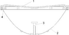
图2是本发明微波天线外罩应用于微波天线时的剖面示意图。Fig. 2 is a schematic cross-sectional view of a microwave antenna cover of the present invention applied to a microwave antenna.
图3是图2中外罩的俯视图。Fig. 3 is a top view of the housing in Fig. 2 .
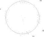
图4是图2中外罩的仰视图。Fig. 4 is a bottom view of the housing in Fig. 2 .
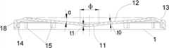
图5是图2中外罩的剖面图。Fig. 5 is a cross-sectional view of the housing in Fig. 2 .
图6是图2的微波天线的工作原理示意图。FIG. 6 is a schematic diagram of the working principle of the microwave antenna in FIG. 2 .
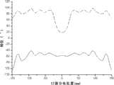
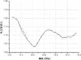
图7是本发明微波天线外罩应用时的典型口面电场相位分布曲线,其中实线表示加外罩的口面相位分布曲线,虚线表示不加外罩的口面相位分布曲线。Fig. 7 is a typical orifice-surface electric field phase distribution curve when the microwave antenna cover of the present invention is applied, wherein the solid line represents the orifice-surface phase distribution curve with the cover, and the dotted line represents the orifice-surface phase distribution curve without the cover.
图8是本发明微波天线外罩应用时的典型输入电压驻波比曲线,其中实线表示加外罩的电压驻波比曲线,虚线表示不加外罩的电压驻波比曲线。Fig. 8 is the typical input voltage standing wave ratio curve when the microwave antenna outer cover of the present invention is applied, and wherein solid line represents the voltage standing wave ratio curve of adding outer cover, and dotted line represents the voltage standing wave ratio curve of not adding outer cover.
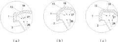
图9是本发明微波天线外罩的辅反射部分的几种实施例及原理示意。Fig. 9 is a schematic diagram of several embodiments and principles of the auxiliary reflection part of the microwave antenna cover of the present invention.
图10是本发明微波天线外罩应用时的典型辐射方向图曲线。Fig. 10 is a typical radiation pattern curve when the microwave antenna cover of the present invention is applied.
图11是揭示本发明微波天线外罩与微波天线其它组件之间装配关系的装配结构示意图。Fig. 11 is a schematic diagram of an assembly structure revealing the assembly relationship between the microwave antenna cover and other components of the microwave antenna of the present invention.
【具体实施方式】【Detailed ways】
下面结合附图和实施例对本发明作进一步的说明:Below in conjunction with accompanying drawing and embodiment the present invention will be further described:
请参阅图2、图3及图4,应用了本发明的微波天线外罩的微波天线包括:一结构旋转对称的赋形介质天线外罩1、若干安装螺柱14及若干限位卡箍件15、以及吸波材料4。外罩1通过附加螺钉5(参阅图11)连接到微波天线反射面2的翻边上,并由限位卡箍件15定位。外罩1自其旋转对称轴向外依次分布有若干同心的构成部分:位于中心区域的补偿部分11、延续自该补偿部分构成该补偿部分的外围的主反射部分12、以及延续自该主反射部分构成该主反射部分的外围的辅反射部分13,每个构成部分均通过特殊赋形设计以改善电气性能。此外,外罩1在其辅反射部分13外围还设置有垂直于外罩各构成部分的用于装配的裙边18。外罩1的裙边18用于与反射面2的翻边28相抵触并螺锁实现装配,进而形成一种整体封闭的天线结构,将微波天线的馈源3封装其内。由此,设有反射面2和馈源3的一侧相对于外罩1而言为遮罩侧,外罩1面向自由空间的一侧为外露侧,定义外罩1的遮罩侧和外露侧将有利于后述的进一步说明。Referring to Fig. 2, Fig. 3 and Fig. 4, the microwave antenna applied with the microwave antenna housing of the present invention comprises: a shape-
天线外罩1需要选取质地均匀、介电常数稳定和损耗低的介质材料,通常采用的材料有ABS、ASA、聚苯乙烯、聚四氟乙烯、聚丙稀、氧化铝、高温陶瓷、玻璃钢以及一些复合材料等。这些材料都有固定的相对介电常数εr和损耗角正切tanδ,以表征材料的电气性能属性。
请参阅图5和图6,外罩1的补偿部分11的厚度小于主反射部分12的厚度,因此补偿部分11比主反射部分12略薄,用于补偿由于馈源3遮挡造成的天线口面中心部分电场分布的相位延迟,从而使得天线口面电场分布的相位更趋于一致,因而提高天线增益和效率;补偿部分11由于外罩1的旋转对称特性而呈现圆形,其直径与馈源直径相等或相当;补偿部分11的剖面形状可以设计成高斯形、锥形、球形等向外罩1的遮罩侧方向(馈源方向)内凹的形状,以使被补偿部分反射回来的自馈源3发出的电磁波22不回到或极少量地回到馈源3,从而减小对天线输入电压驻波比的影响。Please refer to Fig. 5 and Fig. 6, the thickness of the
补偿部分11,是电磁波正向入射的部分,所以要将形状经特殊赋形,将自馈源3发出的电磁波21在补偿部分11的遮罩侧表面上反射的电磁场22,经过反射面2二次反射,使反射的电磁波23不会回到或者极少量地回到馈源3内而被馈源3再次接收,影响天线的整体性能,尤其是输入电压驻波比性能。The
由于馈源3的副反射面对微波天线本身的辐射产生了一定的遮挡效益,使天线口面电场分布的中心部分产生了一定的相位滞后,所以,就通过补偿部分11的厚度调节,对透射的电磁波进行相位补偿,即设计补偿部分11的厚度t1比环锥部分12的厚度t0要薄一些,使最后透过外罩1的口面电场分布的相位更趋于一致,因而提高天线增益和效率。这个补偿部分的直径φ与馈源3副反射面的直径大小相等或相当。Since the sub-reflection surface of the feed source 3 produces a certain shielding effect on the radiation of the microwave antenna itself, the central part of the electric field distribution on the antenna surface produces a certain phase lag. Therefore, by adjusting the thickness of the
参考图7所揭示的一种实施例的口面电场相位分布曲线,由于补偿部分的口面相位分布滞后了约60度,所以,补偿部分11的厚度t1比环锥部分12的厚度t0要略薄一定厚度,使口面电场分布的相位更趋于一致。Referring to the phase distribution curve of the orifice-surface electric field of an embodiment disclosed in FIG. 7 , since the phase distribution of the orifice-surface of the compensation part lags behind by about 60 degrees, the thickness t1 of the
请再结合图5和图6,外罩1的主反射部分12由厚度(t0)约为1/2介质波长、向遮罩侧馈源3方向内凹的斜锥面构成,其锥角经特殊设计而成,使被主反射部分12反射回来的自馈源3发出的电磁波25反射到特定的方向上,而不回到馈源3内;主反射部分12的锥角α设计的原则是使被主反射部分12反射回来的电磁波反射25到偏离馈源3的特定方向上,该方向对应在微波天线整体辐射方向图中不在辐射方向图的主瓣区域内,对应于辐射方向图中的零点角度位置或远旁瓣角度位置尤佳。Please combine Figure 5 and Figure 6 again, the
当电磁波通过介质材料时,会产生多次反射和折射,而反射的能量势必会影响微波天线本身的性能,所以要降低这部分能量,这就要选取合适的主反射部分12的厚度t0来实现:当厚度t0满足1/2介质波长或其整数倍时,电磁波在介质内多次反射和折射产生的路径相位差是2π的整数倍,使反射波相互抵消,而透射波实现了相互叠加,这样主反射部分12的反射系数最小。When electromagnetic waves pass through dielectric materials, multiple reflections and refractions will occur, and the reflected energy will inevitably affect the performance of the microwave antenna itself. Therefore, to reduce this part of energy, it is necessary to select an appropriate thickness t0 of the
主反射部分12的环锥面的锥角α经特殊设计,可以使天线口面正向辐射的电磁波24在锥环面反射的电磁波25固定的反射到180-2α角度方向上:一方面,使反射的电磁波25通过反射面2二次反射不会回到馈源3内,从而减小对天线整体性能影响,尤其是对较宽频带内的输入电压驻波比性能的影响;另一方面,可以将这个反射的电磁波25反射到的特定方向选择性地对应于天线整体辐射方向图中不在辐射方向图的主瓣区域内的位置(辐射方向图中属于主瓣之外的区域),以对应于辐射方向图中的零点角度位置或远旁瓣角度位置尤佳,从而,降低天线罩对天线本身的辐射方向图,尤其是主瓣区域的影响。The cone angle α of the annulus cone surface of the
参阅图8所揭示的一种实施例的输入电压驻波比曲线,将该锥角α的角度选取为3-10度左右,可以看到本发明的外罩1对微波天线整体的输入电压驻波比性能影响较小。Referring to the input voltage standing wave ratio curve of an embodiment disclosed in Fig. 8, the angle of the cone angle α is selected as about 3-10 degrees, and it can be seen that the input voltage standing wave of the
请继续结合图5和图6,外罩1的辅反射部分13整体呈拱形,故朝外罩1的外露侧外凸,其赋形原则是使其内表面16(参阅图9)对边缘绕射电磁波26具有聚束反射的特性,即反射电磁波27可相对集中地聚集到外罩1内某个区域。Please continue to combine Fig. 5 and Fig. 6, the auxiliary
参考图9所揭示的辅反射部分13的形状的几种实例,分别是其中(a)部分的折状拱形、(b)部分的弧状拱形及(c)部分的盖状拱形,此类拱形面16均有聚束反射的特性:外罩1的遮罩侧,天线口面边缘绕射的电磁波26在遮罩侧拱形面16上反射,而这个拱形面16将反射的电磁波27相对集中聚集到外罩1内的某个区域。Referring to several examples of the shape of the auxiliary
进一步,请再回顾图5和图6,在外罩1辅反射部分13对应的区域(于外罩遮罩侧)紧靠外罩1的裙边18装设吸波材料4,吸波材料4的形状一般为具有一定厚度的圆环状,其安装位置可以与辅反射部分13的内表面形状协同设计,保证尽可能地将吸波材料置于外罩1的裙边18和辅反射部分13所共同定义的范围的反射电磁波相对聚集的区域,从而有效吸收反射电磁波27,减少向天线后向绕射的电磁波,进而提高微波天线的F/B性能。Further, please review Fig. 5 and Fig. 6 again, in the area corresponding to the
吸波材料4是可选部件,其在微波天线装配后,被夹持在外罩1的裙边18、辅反射部分13与反射面2的翻边28之间,用于吸收被外罩1辅反射部分13内表面16反射回来的电磁波27以及部分绕射电磁波26;吸波材料可选用泡沫型、海绵型、橡胶型等材质形式。The absorbing
如图10所示,本发明的外罩显著的提高了辐射F/B性能约10dB。As shown in FIG. 10, the housing of the present invention significantly improves the radiation F/B performance by about 10 dB.
参考图11,本发明的微波天线外罩1与反射面2和馈源3装配的示意图中,作为可选部件的吸波材料4可根据需要进行装配,需要安装时,先将吸波材料4固定在外罩1遮罩侧的表面的若干限位卡箍件15上;外罩1与反射面2的整体装配是采用数个螺钉5将反射面2的翻边28与螺柱14相联接,同时通过限位卡箍件15进行定位,保证外罩1与反射面2完全配合以形成紧凑结构。Referring to Fig. 11, in the schematic diagram of the assembly of the
本发明的外罩可以采用模具注塑工艺一次加工成型,包括天线罩上的螺柱14、限位卡箍15均一体成型,由此制备的产品一致性较好,加工成本低。The outer cover of the present invention can be processed and formed by mold injection molding at one time, including the
在机械性能上,本发明与传统的外凸或内凹形天线罩相比,整体的体积较小,同时拱形的辅反射部分13及裙边28又给外罩提供了较好的结构强度,外形也美观。In terms of mechanical performance, compared with the traditional convex or concave radome, the present invention has a smaller overall volume, and at the same time, the arched
因此,本发明的微波天线外罩无论在电气性能还是机械性能上均取得优于传统技术的效果,由其装配而得的微波天线自然优于其它传统同类天线。Therefore, the microwave antenna cover of the present invention is better than the traditional technology in terms of electrical performance and mechanical performance, and the microwave antenna assembled by it is naturally better than other similar traditional antennas.
以上实施例仅用以说明本发明而并非限制本发明所描述的技术方案;因此,尽管本说明书参照上述的各个实施例对本发明已进行了详细的说明,但是,本领域的普通技术人员应当理解,仍然可以对本发明进行修改或者等同替换;而一切不脱离本发明的精神和范围的技术方案及其改进,其均应涵盖在本发明的权利要求范围当中。The above embodiments are only used to illustrate the present invention and are not intended to limit the technical solutions described in the present invention; therefore, although the specification has described the present invention in detail with reference to the above-mentioned embodiments, those of ordinary skill in the art should understand , the present invention can still be modified or equivalently replaced; and all technical solutions and improvements that do not depart from the spirit and scope of the present invention should be covered by the claims of the present invention.
Claims (14)
Translated fromChinesePriority Applications (4)
| Application Number | Priority Date | Filing Date | Title |
|---|---|---|---|
| CN2010102748771ACN101958461B (en) | 2010-09-07 | 2010-09-07 | Microwave antenna and outer cover thereof |
| BR112013005521ABR112013005521A2 (en) | 2010-09-07 | 2010-11-11 | microwave antenna and radome of the same |
| PCT/CN2010/078648WO2012031427A1 (en) | 2010-09-07 | 2010-11-11 | Microwave antenna and its outer cover |
| EP10856889.0AEP2615688B1 (en) | 2010-09-07 | 2010-11-11 | Microwave antenna and its outer cover |
Applications Claiming Priority (1)
| Application Number | Priority Date | Filing Date | Title |
|---|---|---|---|
| CN2010102748771ACN101958461B (en) | 2010-09-07 | 2010-09-07 | Microwave antenna and outer cover thereof |
Publications (2)
| Publication Number | Publication Date |
|---|---|
| CN101958461A CN101958461A (en) | 2011-01-26 |
| CN101958461Btrue CN101958461B (en) | 2013-11-20 |
Family
ID=43485668
Family Applications (1)
| Application Number | Title | Priority Date | Filing Date |
|---|---|---|---|
| CN2010102748771AExpired - Fee RelatedCN101958461B (en) | 2010-09-07 | 2010-09-07 | Microwave antenna and outer cover thereof |
Country Status (4)
| Country | Link |
|---|---|
| EP (1) | EP2615688B1 (en) |
| CN (1) | CN101958461B (en) |
| BR (1) | BR112013005521A2 (en) |
| WO (1) | WO2012031427A1 (en) |
Cited By (127)
| Publication number | Priority date | Publication date | Assignee | Title |
|---|---|---|---|---|
| US9608740B2 (en) | 2015-07-15 | 2017-03-28 | At&T Intellectual Property I, L.P. | Method and apparatus for launching a wave mode that mitigates interference |
| US9640850B2 (en) | 2015-06-25 | 2017-05-02 | At&T Intellectual Property I, L.P. | Methods and apparatus for inducing a non-fundamental wave mode on a transmission medium |
| US9667317B2 (en) | 2015-06-15 | 2017-05-30 | At&T Intellectual Property I, L.P. | Method and apparatus for providing security using network traffic adjustments |
| US9674711B2 (en) | 2013-11-06 | 2017-06-06 | At&T Intellectual Property I, L.P. | Surface-wave communications and methods thereof |
| US9685992B2 (en) | 2014-10-03 | 2017-06-20 | At&T Intellectual Property I, L.P. | Circuit panel network and methods thereof |
| US9705561B2 (en) | 2015-04-24 | 2017-07-11 | At&T Intellectual Property I, L.P. | Directional coupling device and methods for use therewith |
| US9705610B2 (en) | 2014-10-21 | 2017-07-11 | At&T Intellectual Property I, L.P. | Transmission device with impairment compensation and methods for use therewith |
| US9722318B2 (en) | 2015-07-14 | 2017-08-01 | At&T Intellectual Property I, L.P. | Method and apparatus for coupling an antenna to a device |
| US9729197B2 (en) | 2015-10-01 | 2017-08-08 | At&T Intellectual Property I, L.P. | Method and apparatus for communicating network management traffic over a network |
| US9735833B2 (en) | 2015-07-31 | 2017-08-15 | At&T Intellectual Property I, L.P. | Method and apparatus for communications management in a neighborhood network |
| US9742521B2 (en) | 2014-11-20 | 2017-08-22 | At&T Intellectual Property I, L.P. | Transmission device with mode division multiplexing and methods for use therewith |
| US9742462B2 (en) | 2014-12-04 | 2017-08-22 | At&T Intellectual Property I, L.P. | Transmission medium and communication interfaces and methods for use therewith |
| US9749053B2 (en) | 2015-07-23 | 2017-08-29 | At&T Intellectual Property I, L.P. | Node device, repeater and methods for use therewith |
| US9748626B2 (en) | 2015-05-14 | 2017-08-29 | At&T Intellectual Property I, L.P. | Plurality of cables having different cross-sectional shapes which are bundled together to form a transmission medium |
| US9749013B2 (en) | 2015-03-17 | 2017-08-29 | At&T Intellectual Property I, L.P. | Method and apparatus for reducing attenuation of electromagnetic waves guided by a transmission medium |
| US9762289B2 (en) | 2014-10-14 | 2017-09-12 | At&T Intellectual Property I, L.P. | Method and apparatus for transmitting or receiving signals in a transportation system |
| US9769020B2 (en) | 2014-10-21 | 2017-09-19 | At&T Intellectual Property I, L.P. | Method and apparatus for responding to events affecting communications in a communication network |
| US9769128B2 (en) | 2015-09-28 | 2017-09-19 | At&T Intellectual Property I, L.P. | Method and apparatus for encryption of communications over a network |
| US9768833B2 (en) | 2014-09-15 | 2017-09-19 | At&T Intellectual Property I, L.P. | Method and apparatus for sensing a condition in a transmission medium of electromagnetic waves |
| US9780834B2 (en) | 2014-10-21 | 2017-10-03 | At&T Intellectual Property I, L.P. | Method and apparatus for transmitting electromagnetic waves |
| US9787412B2 (en) | 2015-06-25 | 2017-10-10 | At&T Intellectual Property I, L.P. | Methods and apparatus for inducing a fundamental wave mode on a transmission medium |
| US9788326B2 (en) | 2012-12-05 | 2017-10-10 | At&T Intellectual Property I, L.P. | Backhaul link for distributed antenna system |
| US9793951B2 (en) | 2015-07-15 | 2017-10-17 | At&T Intellectual Property I, L.P. | Method and apparatus for launching a wave mode that mitigates interference |
| US9793955B2 (en) | 2015-04-24 | 2017-10-17 | At&T Intellectual Property I, Lp | Passive electrical coupling device and methods for use therewith |
| US9793954B2 (en) | 2015-04-28 | 2017-10-17 | At&T Intellectual Property I, L.P. | Magnetic coupling device and methods for use therewith |
| US9800327B2 (en) | 2014-11-20 | 2017-10-24 | At&T Intellectual Property I, L.P. | Apparatus for controlling operations of a communication device and methods thereof |
| US9820146B2 (en) | 2015-06-12 | 2017-11-14 | At&T Intellectual Property I, L.P. | Method and apparatus for authentication and identity management of communicating devices |
| US9838078B2 (en) | 2015-07-31 | 2017-12-05 | At&T Intellectual Property I, L.P. | Method and apparatus for exchanging communication signals |
| US9838896B1 (en) | 2016-12-09 | 2017-12-05 | At&T Intellectual Property I, L.P. | Method and apparatus for assessing network coverage |
| US9847850B2 (en) | 2014-10-14 | 2017-12-19 | At&T Intellectual Property I, L.P. | Method and apparatus for adjusting a mode of communication in a communication network |
| US9847566B2 (en) | 2015-07-14 | 2017-12-19 | At&T Intellectual Property I, L.P. | Method and apparatus for adjusting a field of a signal to mitigate interference |
| US9853342B2 (en) | 2015-07-14 | 2017-12-26 | At&T Intellectual Property I, L.P. | Dielectric transmission medium connector and methods for use therewith |
| US9860075B1 (en) | 2016-08-26 | 2018-01-02 | At&T Intellectual Property I, L.P. | Method and communication node for broadband distribution |
| US9866309B2 (en) | 2015-06-03 | 2018-01-09 | At&T Intellectual Property I, Lp | Host node device and methods for use therewith |
| US9866276B2 (en) | 2014-10-10 | 2018-01-09 | At&T Intellectual Property I, L.P. | Method and apparatus for arranging communication sessions in a communication system |
| US9865911B2 (en) | 2015-06-25 | 2018-01-09 | At&T Intellectual Property I, L.P. | Waveguide system for slot radiating first electromagnetic waves that are combined into a non-fundamental wave mode second electromagnetic wave on a transmission medium |
| US9871558B2 (en) | 2014-10-21 | 2018-01-16 | At&T Intellectual Property I, L.P. | Guided-wave transmission device and methods for use therewith |
| US9871282B2 (en) | 2015-05-14 | 2018-01-16 | At&T Intellectual Property I, L.P. | At least one transmission medium having a dielectric surface that is covered at least in part by a second dielectric |
| US9871283B2 (en) | 2015-07-23 | 2018-01-16 | At&T Intellectual Property I, Lp | Transmission medium having a dielectric core comprised of plural members connected by a ball and socket configuration |
| US9876264B2 (en) | 2015-10-02 | 2018-01-23 | At&T Intellectual Property I, Lp | Communication system, guided wave switch and methods for use therewith |
| US9876570B2 (en) | 2015-02-20 | 2018-01-23 | At&T Intellectual Property I, Lp | Guided-wave transmission device with non-fundamental mode propagation and methods for use therewith |
| US9876605B1 (en) | 2016-10-21 | 2018-01-23 | At&T Intellectual Property I, L.P. | Launcher and coupling system to support desired guided wave mode |
| US9882257B2 (en) | 2015-07-14 | 2018-01-30 | At&T Intellectual Property I, L.P. | Method and apparatus for launching a wave mode that mitigates interference |
| US9887447B2 (en) | 2015-05-14 | 2018-02-06 | At&T Intellectual Property I, L.P. | Transmission medium having multiple cores and methods for use therewith |
| US9893795B1 (en) | 2016-12-07 | 2018-02-13 | At&T Intellectual Property I, Lp | Method and repeater for broadband distribution |
| US9906269B2 (en) | 2014-09-17 | 2018-02-27 | At&T Intellectual Property I, L.P. | Monitoring and mitigating conditions in a communication network |
| US9912381B2 (en) | 2015-06-03 | 2018-03-06 | At&T Intellectual Property I, Lp | Network termination and methods for use therewith |
| US9911020B1 (en) | 2016-12-08 | 2018-03-06 | At&T Intellectual Property I, L.P. | Method and apparatus for tracking via a radio frequency identification device |
| US9912419B1 (en) | 2016-08-24 | 2018-03-06 | At&T Intellectual Property I, L.P. | Method and apparatus for managing a fault in a distributed antenna system |
| US9913139B2 (en) | 2015-06-09 | 2018-03-06 | At&T Intellectual Property I, L.P. | Signal fingerprinting for authentication of communicating devices |
| US9912033B2 (en) | 2014-10-21 | 2018-03-06 | At&T Intellectual Property I, Lp | Guided wave coupler, coupling module and methods for use therewith |
| US9912027B2 (en) | 2015-07-23 | 2018-03-06 | At&T Intellectual Property I, L.P. | Method and apparatus for exchanging communication signals |
| US9917341B2 (en) | 2015-05-27 | 2018-03-13 | At&T Intellectual Property I, L.P. | Apparatus and method for launching electromagnetic waves and for modifying radial dimensions of the propagating electromagnetic waves |
| US9927517B1 (en) | 2016-12-06 | 2018-03-27 | At&T Intellectual Property I, L.P. | Apparatus and methods for sensing rainfall |
| US9929755B2 (en) | 2015-07-14 | 2018-03-27 | At&T Intellectual Property I, L.P. | Method and apparatus for coupling an antenna to a device |
| US9930668B2 (en) | 2013-05-31 | 2018-03-27 | At&T Intellectual Property I, L.P. | Remote distributed antenna system |
| US9948333B2 (en) | 2015-07-23 | 2018-04-17 | At&T Intellectual Property I, L.P. | Method and apparatus for wireless communications to mitigate interference |
| US9948355B2 (en) | 2014-10-21 | 2018-04-17 | At&T Intellectual Property I, L.P. | Apparatus for providing communication services and methods thereof |
| US9948354B2 (en) | 2015-04-28 | 2018-04-17 | At&T Intellectual Property I, L.P. | Magnetic coupling device with reflective plate and methods for use therewith |
| US9954287B2 (en) | 2014-11-20 | 2018-04-24 | At&T Intellectual Property I, L.P. | Apparatus for converting wireless signals and electromagnetic waves and methods thereof |
| US9954286B2 (en) | 2014-10-21 | 2018-04-24 | At&T Intellectual Property I, L.P. | Guided-wave transmission device with non-fundamental mode propagation and methods for use therewith |
| US9967173B2 (en) | 2015-07-31 | 2018-05-08 | At&T Intellectual Property I, L.P. | Method and apparatus for authentication and identity management of communicating devices |
| US9973940B1 (en) | 2017-02-27 | 2018-05-15 | At&T Intellectual Property I, L.P. | Apparatus and methods for dynamic impedance matching of a guided wave launcher |
| US9973416B2 (en) | 2014-10-02 | 2018-05-15 | At&T Intellectual Property I, L.P. | Method and apparatus that provides fault tolerance in a communication network |
| US9991580B2 (en) | 2016-10-21 | 2018-06-05 | At&T Intellectual Property I, L.P. | Launcher and coupling system for guided wave mode cancellation |
| US9997819B2 (en) | 2015-06-09 | 2018-06-12 | At&T Intellectual Property I, L.P. | Transmission medium and method for facilitating propagation of electromagnetic waves via a core |
| US9999038B2 (en) | 2013-05-31 | 2018-06-12 | At&T Intellectual Property I, L.P. | Remote distributed antenna system |
| US9998870B1 (en) | 2016-12-08 | 2018-06-12 | At&T Intellectual Property I, L.P. | Method and apparatus for proximity sensing |
| US10009067B2 (en) | 2014-12-04 | 2018-06-26 | At&T Intellectual Property I, L.P. | Method and apparatus for configuring a communication interface |
| US10009063B2 (en) | 2015-09-16 | 2018-06-26 | At&T Intellectual Property I, L.P. | Method and apparatus for use with a radio distributed antenna system having an out-of-band reference signal |
| US10020844B2 (en) | 2016-12-06 | 2018-07-10 | T&T Intellectual Property I, L.P. | Method and apparatus for broadcast communication via guided waves |
| US10027398B2 (en) | 2015-06-11 | 2018-07-17 | At&T Intellectual Property I, Lp | Repeater and methods for use therewith |
| US10027397B2 (en) | 2016-12-07 | 2018-07-17 | At&T Intellectual Property I, L.P. | Distributed antenna system and methods for use therewith |
| US10033108B2 (en) | 2015-07-14 | 2018-07-24 | At&T Intellectual Property I, L.P. | Apparatus and methods for generating an electromagnetic wave having a wave mode that mitigates interference |
| US10044409B2 (en) | 2015-07-14 | 2018-08-07 | At&T Intellectual Property I, L.P. | Transmission medium and methods for use therewith |
| US10069535B2 (en) | 2016-12-08 | 2018-09-04 | At&T Intellectual Property I, L.P. | Apparatus and methods for launching electromagnetic waves having a certain electric field structure |
| US10079661B2 (en) | 2015-09-16 | 2018-09-18 | At&T Intellectual Property I, L.P. | Method and apparatus for use with a radio distributed antenna system having a clock reference |
| US10090606B2 (en) | 2015-07-15 | 2018-10-02 | At&T Intellectual Property I, L.P. | Antenna system with dielectric array and methods for use therewith |
| US10090594B2 (en) | 2016-11-23 | 2018-10-02 | At&T Intellectual Property I, L.P. | Antenna system having structural configurations for assembly |
| US10103801B2 (en) | 2015-06-03 | 2018-10-16 | At&T Intellectual Property I, L.P. | Host node device and methods for use therewith |
| US10103422B2 (en) | 2016-12-08 | 2018-10-16 | At&T Intellectual Property I, L.P. | Method and apparatus for mounting network devices |
| US10135145B2 (en) | 2016-12-06 | 2018-11-20 | At&T Intellectual Property I, L.P. | Apparatus and methods for generating an electromagnetic wave along a transmission medium |
| US10135146B2 (en) | 2016-10-18 | 2018-11-20 | At&T Intellectual Property I, L.P. | Apparatus and methods for launching guided waves via circuits |
| US10135147B2 (en) | 2016-10-18 | 2018-11-20 | At&T Intellectual Property I, L.P. | Apparatus and methods for launching guided waves via an antenna |
| US10136434B2 (en) | 2015-09-16 | 2018-11-20 | At&T Intellectual Property I, L.P. | Method and apparatus for use with a radio distributed antenna system having an ultra-wideband control channel |
| US10139820B2 (en) | 2016-12-07 | 2018-11-27 | At&T Intellectual Property I, L.P. | Method and apparatus for deploying equipment of a communication system |
| US10144036B2 (en) | 2015-01-30 | 2018-12-04 | At&T Intellectual Property I, L.P. | Method and apparatus for mitigating interference affecting a propagation of electromagnetic waves guided by a transmission medium |
| US10148016B2 (en) | 2015-07-14 | 2018-12-04 | At&T Intellectual Property I, L.P. | Apparatus and methods for communicating utilizing an antenna array |
| US10170840B2 (en) | 2015-07-14 | 2019-01-01 | At&T Intellectual Property I, L.P. | Apparatus and methods for sending or receiving electromagnetic signals |
| US10168695B2 (en) | 2016-12-07 | 2019-01-01 | At&T Intellectual Property I, L.P. | Method and apparatus for controlling an unmanned aircraft |
| US10178445B2 (en) | 2016-11-23 | 2019-01-08 | At&T Intellectual Property I, L.P. | Methods, devices, and systems for load balancing between a plurality of waveguides |
| US10205655B2 (en) | 2015-07-14 | 2019-02-12 | At&T Intellectual Property I, L.P. | Apparatus and methods for communicating utilizing an antenna array and multiple communication paths |
| US10225025B2 (en) | 2016-11-03 | 2019-03-05 | At&T Intellectual Property I, L.P. | Method and apparatus for detecting a fault in a communication system |
| US10224634B2 (en) | 2016-11-03 | 2019-03-05 | At&T Intellectual Property I, L.P. | Methods and apparatus for adjusting an operational characteristic of an antenna |
| US10243784B2 (en) | 2014-11-20 | 2019-03-26 | At&T Intellectual Property I, L.P. | System for generating topology information and methods thereof |
| US10243270B2 (en) | 2016-12-07 | 2019-03-26 | At&T Intellectual Property I, L.P. | Beam adaptive multi-feed dielectric antenna system and methods for use therewith |
| US10264586B2 (en) | 2016-12-09 | 2019-04-16 | At&T Mobility Ii Llc | Cloud-based packet controller and methods for use therewith |
| US10291334B2 (en) | 2016-11-03 | 2019-05-14 | At&T Intellectual Property I, L.P. | System for detecting a fault in a communication system |
| US10291311B2 (en) | 2016-09-09 | 2019-05-14 | At&T Intellectual Property I, L.P. | Method and apparatus for mitigating a fault in a distributed antenna system |
| US10298293B2 (en) | 2017-03-13 | 2019-05-21 | At&T Intellectual Property I, L.P. | Apparatus of communication utilizing wireless network devices |
| US10305190B2 (en) | 2016-12-01 | 2019-05-28 | At&T Intellectual Property I, L.P. | Reflecting dielectric antenna system and methods for use therewith |
| US10312567B2 (en) | 2016-10-26 | 2019-06-04 | At&T Intellectual Property I, L.P. | Launcher with planar strip antenna and methods for use therewith |
| US10320586B2 (en) | 2015-07-14 | 2019-06-11 | At&T Intellectual Property I, L.P. | Apparatus and methods for generating non-interfering electromagnetic waves on an insulated transmission medium |
| US10326689B2 (en) | 2016-12-08 | 2019-06-18 | At&T Intellectual Property I, L.P. | Method and system for providing alternative communication paths |
| US10326494B2 (en) | 2016-12-06 | 2019-06-18 | At&T Intellectual Property I, L.P. | Apparatus for measurement de-embedding and methods for use therewith |
| US10340603B2 (en) | 2016-11-23 | 2019-07-02 | At&T Intellectual Property I, L.P. | Antenna system having shielded structural configurations for assembly |
| US10340573B2 (en) | 2016-10-26 | 2019-07-02 | At&T Intellectual Property I, L.P. | Launcher with cylindrical coupling device and methods for use therewith |
| US10340983B2 (en) | 2016-12-09 | 2019-07-02 | At&T Intellectual Property I, L.P. | Method and apparatus for surveying remote sites via guided wave communications |
| US10340600B2 (en) | 2016-10-18 | 2019-07-02 | At&T Intellectual Property I, L.P. | Apparatus and methods for launching guided waves via plural waveguide systems |
| US10341142B2 (en) | 2015-07-14 | 2019-07-02 | At&T Intellectual Property I, L.P. | Apparatus and methods for generating non-interfering electromagnetic waves on an uninsulated conductor |
| US10340601B2 (en) | 2016-11-23 | 2019-07-02 | At&T Intellectual Property I, L.P. | Multi-antenna system and methods for use therewith |
| US10355367B2 (en) | 2015-10-16 | 2019-07-16 | At&T Intellectual Property I, L.P. | Antenna structure for exchanging wireless signals |
| US10359749B2 (en) | 2016-12-07 | 2019-07-23 | At&T Intellectual Property I, L.P. | Method and apparatus for utilities management via guided wave communication |
| US10361489B2 (en) | 2016-12-01 | 2019-07-23 | At&T Intellectual Property I, L.P. | Dielectric dish antenna system and methods for use therewith |
| US10374316B2 (en) | 2016-10-21 | 2019-08-06 | At&T Intellectual Property I, L.P. | System and dielectric antenna with non-uniform dielectric |
| US10382976B2 (en) | 2016-12-06 | 2019-08-13 | At&T Intellectual Property I, L.P. | Method and apparatus for managing wireless communications based on communication paths and network device positions |
| US10389029B2 (en) | 2016-12-07 | 2019-08-20 | At&T Intellectual Property I, L.P. | Multi-feed dielectric antenna system with core selection and methods for use therewith |
| US10389037B2 (en) | 2016-12-08 | 2019-08-20 | At&T Intellectual Property I, L.P. | Apparatus and methods for selecting sections of an antenna array and use therewith |
| US10411356B2 (en) | 2016-12-08 | 2019-09-10 | At&T Intellectual Property I, L.P. | Apparatus and methods for selectively targeting communication devices with an antenna array |
| US10439675B2 (en) | 2016-12-06 | 2019-10-08 | At&T Intellectual Property I, L.P. | Method and apparatus for repeating guided wave communication signals |
| US10446936B2 (en) | 2016-12-07 | 2019-10-15 | At&T Intellectual Property I, L.P. | Multi-feed dielectric antenna system and methods for use therewith |
| US10498044B2 (en) | 2016-11-03 | 2019-12-03 | At&T Intellectual Property I, L.P. | Apparatus for configuring a surface of an antenna |
| US10530505B2 (en) | 2016-12-08 | 2020-01-07 | At&T Intellectual Property I, L.P. | Apparatus and methods for launching electromagnetic waves along a transmission medium |
| US10535928B2 (en) | 2016-11-23 | 2020-01-14 | At&T Intellectual Property I, L.P. | Antenna system and methods for use therewith |
| US10547348B2 (en) | 2016-12-07 | 2020-01-28 | At&T Intellectual Property I, L.P. | Method and apparatus for switching transmission mediums in a communication system |
| US10637149B2 (en) | 2016-12-06 | 2020-04-28 | At&T Intellectual Property I, L.P. | Injection molded dielectric antenna and methods for use therewith |
| US10650940B2 (en) | 2015-05-15 | 2020-05-12 | At&T Intellectual Property I, L.P. | Transmission medium having a conductive material and methods for use therewith |
Families Citing this family (24)
| Publication number | Priority date | Publication date | Assignee | Title |
|---|---|---|---|---|
| CN102280709A (en)* | 2011-05-27 | 2011-12-14 | 京信通信系统(中国)有限公司 | Outer cover of broadband shaped antenna and microwave antenna |
| CN102307359B (en)* | 2011-08-22 | 2014-07-09 | 北京交通大学 | Method for improving covering range of field intensity of wireless communication network |
| US9577323B2 (en) | 2014-03-07 | 2017-02-21 | Commscope Technologies Llc | Radome—reflector assembly mechanism |
| EP2924804A1 (en)* | 2014-03-28 | 2015-09-30 | Alcatel- Lucent Shanghai Bell Co., Ltd | Radome with absorbent device, and antenna comprising same |
| US10812174B2 (en) | 2015-06-03 | 2020-10-20 | At&T Intellectual Property I, L.P. | Client node device and methods for use therewith |
| US11032819B2 (en) | 2016-09-15 | 2021-06-08 | At&T Intellectual Property I, L.P. | Method and apparatus for use with a radio distributed antenna system having a control channel reference signal |
| US10811767B2 (en) | 2016-10-21 | 2020-10-20 | At&T Intellectual Property I, L.P. | System and dielectric antenna with convex dielectric radome |
| US10694379B2 (en) | 2016-12-06 | 2020-06-23 | At&T Intellectual Property I, L.P. | Waveguide system with device-based authentication and methods for use therewith |
| US10727599B2 (en) | 2016-12-06 | 2020-07-28 | At&T Intellectual Property I, L.P. | Launcher with slot antenna and methods for use therewith |
| US10819035B2 (en) | 2016-12-06 | 2020-10-27 | At&T Intellectual Property I, L.P. | Launcher with helical antenna and methods for use therewith |
| US10755542B2 (en) | 2016-12-06 | 2020-08-25 | At&T Intellectual Property I, L.P. | Method and apparatus for surveillance via guided wave communication |
| US10916969B2 (en) | 2016-12-08 | 2021-02-09 | At&T Intellectual Property I, L.P. | Method and apparatus for providing power using an inductive coupling |
| US10601494B2 (en) | 2016-12-08 | 2020-03-24 | At&T Intellectual Property I, L.P. | Dual-band communication device and method for use therewith |
| US10938108B2 (en) | 2016-12-08 | 2021-03-02 | At&T Intellectual Property I, L.P. | Frequency selective multi-feed dielectric antenna system and methods for use therewith |
| US10777873B2 (en) | 2016-12-08 | 2020-09-15 | At&T Intellectual Property I, L.P. | Method and apparatus for mounting network devices |
| CN107538599B (en)* | 2017-08-14 | 2019-08-23 | 湖北三江航天江北机械工程有限公司 | Based on Wrapping formed special-shaped negative cruvature composite ceramic wave-transparent antenna house cover preparation method |
| CN108461916B (en)* | 2018-02-13 | 2020-04-17 | 广东通宇通讯股份有限公司 | Broadband flexible antenna housing of microwave antenna |
| CN108963417A (en)* | 2018-08-30 | 2018-12-07 | 广东通宇通讯股份有限公司 | A kind of microwave antenna being easily achieved different frequency range switching |
| US11385325B2 (en) | 2019-08-07 | 2022-07-12 | Waymo Llc | Corrugated radomes |
| US20230272200A1 (en)* | 2020-06-29 | 2023-08-31 | Sabic Global Technologies B.V. | Polymer composition with improved flowability and falling weight impact resistance at low temperature |
| CN112635990B (en)* | 2021-01-05 | 2023-06-13 | 大连海事大学 | Digital television transmitting antenna housing |
| US11476568B2 (en) | 2021-02-09 | 2022-10-18 | Jabil Inc. | Radome with aperture and method making same |
| CN113140908A (en)* | 2021-04-15 | 2021-07-20 | 大连海事大学 | Antenna housing of broadband circularly polarized satellite navigation mobile terminal |
| CN114243255A (en)* | 2022-01-14 | 2022-03-25 | 东莞东石新材料开发有限公司 | Millimeter wave antenna structure |
Citations (2)
| Publication number | Priority date | Publication date | Assignee | Title |
|---|---|---|---|---|
| CN2408577Y (en)* | 2000-03-02 | 2000-11-29 | 寰波科技股份有限公司 | Parabolic reflector antenna |
| CN201859944U (en)* | 2010-09-07 | 2011-06-08 | 京信通信系统(中国)有限公司 | Microwave antenna and outer housing thereof |
Family Cites Families (10)
| Publication number | Priority date | Publication date | Assignee | Title |
|---|---|---|---|---|
| US4581615A (en)* | 1983-02-08 | 1986-04-08 | Levy Stanley P | Double reflector antenna with integral radome reflector support |
| EP0170726A1 (en)* | 1984-07-13 | 1986-02-12 | Siemens Aktiengesellschaft | Dual reflector directional antenna |
| US6150991A (en)* | 1998-11-12 | 2000-11-21 | Raytheon Company | Electronically scanned cassegrain antenna with full aperture secondary/radome |
| JP3871255B2 (en)* | 2001-11-01 | 2007-01-24 | アンテン株式会社 | Radome |
| US7042407B2 (en)* | 2003-08-14 | 2006-05-09 | Andrew Corporation | Dual radius twist lock radome and reflector antenna for radome |
| US7138953B2 (en)* | 2004-01-29 | 2006-11-21 | Malibu Research Associates | Method and apparatus for reducing the effects of collector blockage in a reflector antenna |
| US7138958B2 (en)* | 2004-02-27 | 2006-11-21 | Andrew Corporation | Reflector antenna radome with backlobe suppressor ring and method of manufacturing |
| FR2894391B1 (en)* | 2005-12-06 | 2008-01-04 | Alcatel Sa | RADIO COMMUNICATION ANTENNA WITH RADOME AND METHOD FOR ASSEMBLING SUCH A RADIO RADIO ANTENNA WITH RADOME |
| JP4557177B2 (en)* | 2006-09-04 | 2010-10-06 | トヨタ自動車株式会社 | Antenna device |
| WO2010064660A1 (en)* | 2008-12-05 | 2010-06-10 | 日本電気株式会社 | Antenna device and communication device provided therewith |
- 2010
- 2010-09-07CNCN2010102748771Apatent/CN101958461B/ennot_activeExpired - Fee Related
- 2010-11-11BRBR112013005521Apatent/BR112013005521A2/ennot_activeApplication Discontinuation
- 2010-11-11WOPCT/CN2010/078648patent/WO2012031427A1/enactiveApplication Filing
- 2010-11-11EPEP10856889.0Apatent/EP2615688B1/ennot_activeNot-in-force
Patent Citations (2)
| Publication number | Priority date | Publication date | Assignee | Title |
|---|---|---|---|---|
| CN2408577Y (en)* | 2000-03-02 | 2000-11-29 | 寰波科技股份有限公司 | Parabolic reflector antenna |
| CN201859944U (en)* | 2010-09-07 | 2011-06-08 | 京信通信系统(中国)有限公司 | Microwave antenna and outer housing thereof |
Cited By (143)
| Publication number | Priority date | Publication date | Assignee | Title |
|---|---|---|---|---|
| US9788326B2 (en) | 2012-12-05 | 2017-10-10 | At&T Intellectual Property I, L.P. | Backhaul link for distributed antenna system |
| US9930668B2 (en) | 2013-05-31 | 2018-03-27 | At&T Intellectual Property I, L.P. | Remote distributed antenna system |
| US10051630B2 (en) | 2013-05-31 | 2018-08-14 | At&T Intellectual Property I, L.P. | Remote distributed antenna system |
| US9999038B2 (en) | 2013-05-31 | 2018-06-12 | At&T Intellectual Property I, L.P. | Remote distributed antenna system |
| US10091787B2 (en) | 2013-05-31 | 2018-10-02 | At&T Intellectual Property I, L.P. | Remote distributed antenna system |
| US9674711B2 (en) | 2013-11-06 | 2017-06-06 | At&T Intellectual Property I, L.P. | Surface-wave communications and methods thereof |
| US9768833B2 (en) | 2014-09-15 | 2017-09-19 | At&T Intellectual Property I, L.P. | Method and apparatus for sensing a condition in a transmission medium of electromagnetic waves |
| US9906269B2 (en) | 2014-09-17 | 2018-02-27 | At&T Intellectual Property I, L.P. | Monitoring and mitigating conditions in a communication network |
| US10063280B2 (en) | 2014-09-17 | 2018-08-28 | At&T Intellectual Property I, L.P. | Monitoring and mitigating conditions in a communication network |
| US9973416B2 (en) | 2014-10-02 | 2018-05-15 | At&T Intellectual Property I, L.P. | Method and apparatus that provides fault tolerance in a communication network |
| US9685992B2 (en) | 2014-10-03 | 2017-06-20 | At&T Intellectual Property I, L.P. | Circuit panel network and methods thereof |
| US9866276B2 (en) | 2014-10-10 | 2018-01-09 | At&T Intellectual Property I, L.P. | Method and apparatus for arranging communication sessions in a communication system |
| US9762289B2 (en) | 2014-10-14 | 2017-09-12 | At&T Intellectual Property I, L.P. | Method and apparatus for transmitting or receiving signals in a transportation system |
| US9847850B2 (en) | 2014-10-14 | 2017-12-19 | At&T Intellectual Property I, L.P. | Method and apparatus for adjusting a mode of communication in a communication network |
| US9780834B2 (en) | 2014-10-21 | 2017-10-03 | At&T Intellectual Property I, L.P. | Method and apparatus for transmitting electromagnetic waves |
| US9912033B2 (en) | 2014-10-21 | 2018-03-06 | At&T Intellectual Property I, Lp | Guided wave coupler, coupling module and methods for use therewith |
| US9871558B2 (en) | 2014-10-21 | 2018-01-16 | At&T Intellectual Property I, L.P. | Guided-wave transmission device and methods for use therewith |
| US9769020B2 (en) | 2014-10-21 | 2017-09-19 | At&T Intellectual Property I, L.P. | Method and apparatus for responding to events affecting communications in a communication network |
| US9876587B2 (en) | 2014-10-21 | 2018-01-23 | At&T Intellectual Property I, L.P. | Transmission device with impairment compensation and methods for use therewith |
| US9948355B2 (en) | 2014-10-21 | 2018-04-17 | At&T Intellectual Property I, L.P. | Apparatus for providing communication services and methods thereof |
| US9705610B2 (en) | 2014-10-21 | 2017-07-11 | At&T Intellectual Property I, L.P. | Transmission device with impairment compensation and methods for use therewith |
| US9960808B2 (en) | 2014-10-21 | 2018-05-01 | At&T Intellectual Property I, L.P. | Guided-wave transmission device and methods for use therewith |
| US9954286B2 (en) | 2014-10-21 | 2018-04-24 | At&T Intellectual Property I, L.P. | Guided-wave transmission device with non-fundamental mode propagation and methods for use therewith |
| US9749083B2 (en) | 2014-11-20 | 2017-08-29 | At&T Intellectual Property I, L.P. | Transmission device with mode division multiplexing and methods for use therewith |
| US9800327B2 (en) | 2014-11-20 | 2017-10-24 | At&T Intellectual Property I, L.P. | Apparatus for controlling operations of a communication device and methods thereof |
| US9742521B2 (en) | 2014-11-20 | 2017-08-22 | At&T Intellectual Property I, L.P. | Transmission device with mode division multiplexing and methods for use therewith |
| US10243784B2 (en) | 2014-11-20 | 2019-03-26 | At&T Intellectual Property I, L.P. | System for generating topology information and methods thereof |
| US9954287B2 (en) | 2014-11-20 | 2018-04-24 | At&T Intellectual Property I, L.P. | Apparatus for converting wireless signals and electromagnetic waves and methods thereof |
| US10009067B2 (en) | 2014-12-04 | 2018-06-26 | At&T Intellectual Property I, L.P. | Method and apparatus for configuring a communication interface |
| US9742462B2 (en) | 2014-12-04 | 2017-08-22 | At&T Intellectual Property I, L.P. | Transmission medium and communication interfaces and methods for use therewith |
| US10144036B2 (en) | 2015-01-30 | 2018-12-04 | At&T Intellectual Property I, L.P. | Method and apparatus for mitigating interference affecting a propagation of electromagnetic waves guided by a transmission medium |
| US9876571B2 (en) | 2015-02-20 | 2018-01-23 | At&T Intellectual Property I, Lp | Guided-wave transmission device with non-fundamental mode propagation and methods for use therewith |
| US9876570B2 (en) | 2015-02-20 | 2018-01-23 | At&T Intellectual Property I, Lp | Guided-wave transmission device with non-fundamental mode propagation and methods for use therewith |
| US9749013B2 (en) | 2015-03-17 | 2017-08-29 | At&T Intellectual Property I, L.P. | Method and apparatus for reducing attenuation of electromagnetic waves guided by a transmission medium |
| US10224981B2 (en) | 2015-04-24 | 2019-03-05 | At&T Intellectual Property I, Lp | Passive electrical coupling device and methods for use therewith |
| US9831912B2 (en) | 2015-04-24 | 2017-11-28 | At&T Intellectual Property I, Lp | Directional coupling device and methods for use therewith |
| US9705561B2 (en) | 2015-04-24 | 2017-07-11 | At&T Intellectual Property I, L.P. | Directional coupling device and methods for use therewith |
| US9793955B2 (en) | 2015-04-24 | 2017-10-17 | At&T Intellectual Property I, Lp | Passive electrical coupling device and methods for use therewith |
| US9948354B2 (en) | 2015-04-28 | 2018-04-17 | At&T Intellectual Property I, L.P. | Magnetic coupling device with reflective plate and methods for use therewith |
| US9793954B2 (en) | 2015-04-28 | 2017-10-17 | At&T Intellectual Property I, L.P. | Magnetic coupling device and methods for use therewith |
| US9887447B2 (en) | 2015-05-14 | 2018-02-06 | At&T Intellectual Property I, L.P. | Transmission medium having multiple cores and methods for use therewith |
| US9748626B2 (en) | 2015-05-14 | 2017-08-29 | At&T Intellectual Property I, L.P. | Plurality of cables having different cross-sectional shapes which are bundled together to form a transmission medium |
| US9871282B2 (en) | 2015-05-14 | 2018-01-16 | At&T Intellectual Property I, L.P. | At least one transmission medium having a dielectric surface that is covered at least in part by a second dielectric |
| US10650940B2 (en) | 2015-05-15 | 2020-05-12 | At&T Intellectual Property I, L.P. | Transmission medium having a conductive material and methods for use therewith |
| US9917341B2 (en) | 2015-05-27 | 2018-03-13 | At&T Intellectual Property I, L.P. | Apparatus and method for launching electromagnetic waves and for modifying radial dimensions of the propagating electromagnetic waves |
| US9912381B2 (en) | 2015-06-03 | 2018-03-06 | At&T Intellectual Property I, Lp | Network termination and methods for use therewith |
| US9912382B2 (en) | 2015-06-03 | 2018-03-06 | At&T Intellectual Property I, Lp | Network termination and methods for use therewith |
| US10050697B2 (en) | 2015-06-03 | 2018-08-14 | At&T Intellectual Property I, L.P. | Host node device and methods for use therewith |
| US9967002B2 (en) | 2015-06-03 | 2018-05-08 | At&T Intellectual I, Lp | Network termination and methods for use therewith |
| US10103801B2 (en) | 2015-06-03 | 2018-10-16 | At&T Intellectual Property I, L.P. | Host node device and methods for use therewith |
| US9866309B2 (en) | 2015-06-03 | 2018-01-09 | At&T Intellectual Property I, Lp | Host node device and methods for use therewith |
| US9935703B2 (en) | 2015-06-03 | 2018-04-03 | At&T Intellectual Property I, L.P. | Host node device and methods for use therewith |
| US9997819B2 (en) | 2015-06-09 | 2018-06-12 | At&T Intellectual Property I, L.P. | Transmission medium and method for facilitating propagation of electromagnetic waves via a core |
| US9913139B2 (en) | 2015-06-09 | 2018-03-06 | At&T Intellectual Property I, L.P. | Signal fingerprinting for authentication of communicating devices |
| US10142010B2 (en) | 2015-06-11 | 2018-11-27 | At&T Intellectual Property I, L.P. | Repeater and methods for use therewith |
| US10027398B2 (en) | 2015-06-11 | 2018-07-17 | At&T Intellectual Property I, Lp | Repeater and methods for use therewith |
| US9820146B2 (en) | 2015-06-12 | 2017-11-14 | At&T Intellectual Property I, L.P. | Method and apparatus for authentication and identity management of communicating devices |
| US9667317B2 (en) | 2015-06-15 | 2017-05-30 | At&T Intellectual Property I, L.P. | Method and apparatus for providing security using network traffic adjustments |
| US9865911B2 (en) | 2015-06-25 | 2018-01-09 | At&T Intellectual Property I, L.P. | Waveguide system for slot radiating first electromagnetic waves that are combined into a non-fundamental wave mode second electromagnetic wave on a transmission medium |
| US10069185B2 (en) | 2015-06-25 | 2018-09-04 | At&T Intellectual Property I, L.P. | Methods and apparatus for inducing a non-fundamental wave mode on a transmission medium |
| US9640850B2 (en) | 2015-06-25 | 2017-05-02 | At&T Intellectual Property I, L.P. | Methods and apparatus for inducing a non-fundamental wave mode on a transmission medium |
| US9787412B2 (en) | 2015-06-25 | 2017-10-10 | At&T Intellectual Property I, L.P. | Methods and apparatus for inducing a fundamental wave mode on a transmission medium |
| US9722318B2 (en) | 2015-07-14 | 2017-08-01 | At&T Intellectual Property I, L.P. | Method and apparatus for coupling an antenna to a device |
| US10341142B2 (en) | 2015-07-14 | 2019-07-02 | At&T Intellectual Property I, L.P. | Apparatus and methods for generating non-interfering electromagnetic waves on an uninsulated conductor |
| US10044409B2 (en) | 2015-07-14 | 2018-08-07 | At&T Intellectual Property I, L.P. | Transmission medium and methods for use therewith |
| US10170840B2 (en) | 2015-07-14 | 2019-01-01 | At&T Intellectual Property I, L.P. | Apparatus and methods for sending or receiving electromagnetic signals |
| US10148016B2 (en) | 2015-07-14 | 2018-12-04 | At&T Intellectual Property I, L.P. | Apparatus and methods for communicating utilizing an antenna array |
| US9882257B2 (en) | 2015-07-14 | 2018-01-30 | At&T Intellectual Property I, L.P. | Method and apparatus for launching a wave mode that mitigates interference |
| US9929755B2 (en) | 2015-07-14 | 2018-03-27 | At&T Intellectual Property I, L.P. | Method and apparatus for coupling an antenna to a device |
| US10320586B2 (en) | 2015-07-14 | 2019-06-11 | At&T Intellectual Property I, L.P. | Apparatus and methods for generating non-interfering electromagnetic waves on an insulated transmission medium |
| US10205655B2 (en) | 2015-07-14 | 2019-02-12 | At&T Intellectual Property I, L.P. | Apparatus and methods for communicating utilizing an antenna array and multiple communication paths |
| US9853342B2 (en) | 2015-07-14 | 2017-12-26 | At&T Intellectual Property I, L.P. | Dielectric transmission medium connector and methods for use therewith |
| US10033108B2 (en) | 2015-07-14 | 2018-07-24 | At&T Intellectual Property I, L.P. | Apparatus and methods for generating an electromagnetic wave having a wave mode that mitigates interference |
| US9847566B2 (en) | 2015-07-14 | 2017-12-19 | At&T Intellectual Property I, L.P. | Method and apparatus for adjusting a field of a signal to mitigate interference |
| US10090606B2 (en) | 2015-07-15 | 2018-10-02 | At&T Intellectual Property I, L.P. | Antenna system with dielectric array and methods for use therewith |
| US9608740B2 (en) | 2015-07-15 | 2017-03-28 | At&T Intellectual Property I, L.P. | Method and apparatus for launching a wave mode that mitigates interference |
| US9793951B2 (en) | 2015-07-15 | 2017-10-17 | At&T Intellectual Property I, L.P. | Method and apparatus for launching a wave mode that mitigates interference |
| US9948333B2 (en) | 2015-07-23 | 2018-04-17 | At&T Intellectual Property I, L.P. | Method and apparatus for wireless communications to mitigate interference |
| US9912027B2 (en) | 2015-07-23 | 2018-03-06 | At&T Intellectual Property I, L.P. | Method and apparatus for exchanging communication signals |
| US9749053B2 (en) | 2015-07-23 | 2017-08-29 | At&T Intellectual Property I, L.P. | Node device, repeater and methods for use therewith |
| US9806818B2 (en) | 2015-07-23 | 2017-10-31 | At&T Intellectual Property I, Lp | Node device, repeater and methods for use therewith |
| US9871283B2 (en) | 2015-07-23 | 2018-01-16 | At&T Intellectual Property I, Lp | Transmission medium having a dielectric core comprised of plural members connected by a ball and socket configuration |
| US9967173B2 (en) | 2015-07-31 | 2018-05-08 | At&T Intellectual Property I, L.P. | Method and apparatus for authentication and identity management of communicating devices |
| US9838078B2 (en) | 2015-07-31 | 2017-12-05 | At&T Intellectual Property I, L.P. | Method and apparatus for exchanging communication signals |
| US9735833B2 (en) | 2015-07-31 | 2017-08-15 | At&T Intellectual Property I, L.P. | Method and apparatus for communications management in a neighborhood network |
| US10009063B2 (en) | 2015-09-16 | 2018-06-26 | At&T Intellectual Property I, L.P. | Method and apparatus for use with a radio distributed antenna system having an out-of-band reference signal |
| US10136434B2 (en) | 2015-09-16 | 2018-11-20 | At&T Intellectual Property I, L.P. | Method and apparatus for use with a radio distributed antenna system having an ultra-wideband control channel |
| US10079661B2 (en) | 2015-09-16 | 2018-09-18 | At&T Intellectual Property I, L.P. | Method and apparatus for use with a radio distributed antenna system having a clock reference |
| US9769128B2 (en) | 2015-09-28 | 2017-09-19 | At&T Intellectual Property I, L.P. | Method and apparatus for encryption of communications over a network |
| US9729197B2 (en) | 2015-10-01 | 2017-08-08 | At&T Intellectual Property I, L.P. | Method and apparatus for communicating network management traffic over a network |
| US9876264B2 (en) | 2015-10-02 | 2018-01-23 | At&T Intellectual Property I, Lp | Communication system, guided wave switch and methods for use therewith |
| US10355367B2 (en) | 2015-10-16 | 2019-07-16 | At&T Intellectual Property I, L.P. | Antenna structure for exchanging wireless signals |
| US9912419B1 (en) | 2016-08-24 | 2018-03-06 | At&T Intellectual Property I, L.P. | Method and apparatus for managing a fault in a distributed antenna system |
| US9860075B1 (en) | 2016-08-26 | 2018-01-02 | At&T Intellectual Property I, L.P. | Method and communication node for broadband distribution |
| US10291311B2 (en) | 2016-09-09 | 2019-05-14 | At&T Intellectual Property I, L.P. | Method and apparatus for mitigating a fault in a distributed antenna system |
| US10340600B2 (en) | 2016-10-18 | 2019-07-02 | At&T Intellectual Property I, L.P. | Apparatus and methods for launching guided waves via plural waveguide systems |
| US10135146B2 (en) | 2016-10-18 | 2018-11-20 | At&T Intellectual Property I, L.P. | Apparatus and methods for launching guided waves via circuits |
| US10135147B2 (en) | 2016-10-18 | 2018-11-20 | At&T Intellectual Property I, L.P. | Apparatus and methods for launching guided waves via an antenna |
| US9991580B2 (en) | 2016-10-21 | 2018-06-05 | At&T Intellectual Property I, L.P. | Launcher and coupling system for guided wave mode cancellation |
| US10374316B2 (en) | 2016-10-21 | 2019-08-06 | At&T Intellectual Property I, L.P. | System and dielectric antenna with non-uniform dielectric |
| US9876605B1 (en) | 2016-10-21 | 2018-01-23 | At&T Intellectual Property I, L.P. | Launcher and coupling system to support desired guided wave mode |
| US10340573B2 (en) | 2016-10-26 | 2019-07-02 | At&T Intellectual Property I, L.P. | Launcher with cylindrical coupling device and methods for use therewith |
| US10312567B2 (en) | 2016-10-26 | 2019-06-04 | At&T Intellectual Property I, L.P. | Launcher with planar strip antenna and methods for use therewith |
| US10291334B2 (en) | 2016-11-03 | 2019-05-14 | At&T Intellectual Property I, L.P. | System for detecting a fault in a communication system |
| US10225025B2 (en) | 2016-11-03 | 2019-03-05 | At&T Intellectual Property I, L.P. | Method and apparatus for detecting a fault in a communication system |
| US10224634B2 (en) | 2016-11-03 | 2019-03-05 | At&T Intellectual Property I, L.P. | Methods and apparatus for adjusting an operational characteristic of an antenna |
| US10498044B2 (en) | 2016-11-03 | 2019-12-03 | At&T Intellectual Property I, L.P. | Apparatus for configuring a surface of an antenna |
| US10178445B2 (en) | 2016-11-23 | 2019-01-08 | At&T Intellectual Property I, L.P. | Methods, devices, and systems for load balancing between a plurality of waveguides |
| US10535928B2 (en) | 2016-11-23 | 2020-01-14 | At&T Intellectual Property I, L.P. | Antenna system and methods for use therewith |
| US10340601B2 (en) | 2016-11-23 | 2019-07-02 | At&T Intellectual Property I, L.P. | Multi-antenna system and methods for use therewith |
| US10090594B2 (en) | 2016-11-23 | 2018-10-02 | At&T Intellectual Property I, L.P. | Antenna system having structural configurations for assembly |
| US10340603B2 (en) | 2016-11-23 | 2019-07-02 | At&T Intellectual Property I, L.P. | Antenna system having shielded structural configurations for assembly |
| US10305190B2 (en) | 2016-12-01 | 2019-05-28 | At&T Intellectual Property I, L.P. | Reflecting dielectric antenna system and methods for use therewith |
| US10361489B2 (en) | 2016-12-01 | 2019-07-23 | At&T Intellectual Property I, L.P. | Dielectric dish antenna system and methods for use therewith |
| US10382976B2 (en) | 2016-12-06 | 2019-08-13 | At&T Intellectual Property I, L.P. | Method and apparatus for managing wireless communications based on communication paths and network device positions |
| US9927517B1 (en) | 2016-12-06 | 2018-03-27 | At&T Intellectual Property I, L.P. | Apparatus and methods for sensing rainfall |
| US10439675B2 (en) | 2016-12-06 | 2019-10-08 | At&T Intellectual Property I, L.P. | Method and apparatus for repeating guided wave communication signals |
| US10135145B2 (en) | 2016-12-06 | 2018-11-20 | At&T Intellectual Property I, L.P. | Apparatus and methods for generating an electromagnetic wave along a transmission medium |
| US10020844B2 (en) | 2016-12-06 | 2018-07-10 | T&T Intellectual Property I, L.P. | Method and apparatus for broadcast communication via guided waves |
| US10637149B2 (en) | 2016-12-06 | 2020-04-28 | At&T Intellectual Property I, L.P. | Injection molded dielectric antenna and methods for use therewith |
| US10326494B2 (en) | 2016-12-06 | 2019-06-18 | At&T Intellectual Property I, L.P. | Apparatus for measurement de-embedding and methods for use therewith |
| US10027397B2 (en) | 2016-12-07 | 2018-07-17 | At&T Intellectual Property I, L.P. | Distributed antenna system and methods for use therewith |
| US10547348B2 (en) | 2016-12-07 | 2020-01-28 | At&T Intellectual Property I, L.P. | Method and apparatus for switching transmission mediums in a communication system |
| US9893795B1 (en) | 2016-12-07 | 2018-02-13 | At&T Intellectual Property I, Lp | Method and repeater for broadband distribution |
| US10168695B2 (en) | 2016-12-07 | 2019-01-01 | At&T Intellectual Property I, L.P. | Method and apparatus for controlling an unmanned aircraft |
| US10446936B2 (en) | 2016-12-07 | 2019-10-15 | At&T Intellectual Property I, L.P. | Multi-feed dielectric antenna system and methods for use therewith |
| US10243270B2 (en) | 2016-12-07 | 2019-03-26 | At&T Intellectual Property I, L.P. | Beam adaptive multi-feed dielectric antenna system and methods for use therewith |
| US10139820B2 (en) | 2016-12-07 | 2018-11-27 | At&T Intellectual Property I, L.P. | Method and apparatus for deploying equipment of a communication system |
| US10359749B2 (en) | 2016-12-07 | 2019-07-23 | At&T Intellectual Property I, L.P. | Method and apparatus for utilities management via guided wave communication |
| US10389029B2 (en) | 2016-12-07 | 2019-08-20 | At&T Intellectual Property I, L.P. | Multi-feed dielectric antenna system with core selection and methods for use therewith |
| US9911020B1 (en) | 2016-12-08 | 2018-03-06 | At&T Intellectual Property I, L.P. | Method and apparatus for tracking via a radio frequency identification device |
| US9998870B1 (en) | 2016-12-08 | 2018-06-12 | At&T Intellectual Property I, L.P. | Method and apparatus for proximity sensing |
| US10389037B2 (en) | 2016-12-08 | 2019-08-20 | At&T Intellectual Property I, L.P. | Apparatus and methods for selecting sections of an antenna array and use therewith |
| US10411356B2 (en) | 2016-12-08 | 2019-09-10 | At&T Intellectual Property I, L.P. | Apparatus and methods for selectively targeting communication devices with an antenna array |
| US10069535B2 (en) | 2016-12-08 | 2018-09-04 | At&T Intellectual Property I, L.P. | Apparatus and methods for launching electromagnetic waves having a certain electric field structure |
| US10530505B2 (en) | 2016-12-08 | 2020-01-07 | At&T Intellectual Property I, L.P. | Apparatus and methods for launching electromagnetic waves along a transmission medium |
| US10326689B2 (en) | 2016-12-08 | 2019-06-18 | At&T Intellectual Property I, L.P. | Method and system for providing alternative communication paths |
| US10103422B2 (en) | 2016-12-08 | 2018-10-16 | At&T Intellectual Property I, L.P. | Method and apparatus for mounting network devices |
| US9838896B1 (en) | 2016-12-09 | 2017-12-05 | At&T Intellectual Property I, L.P. | Method and apparatus for assessing network coverage |
| US10340983B2 (en) | 2016-12-09 | 2019-07-02 | At&T Intellectual Property I, L.P. | Method and apparatus for surveying remote sites via guided wave communications |
| US10264586B2 (en) | 2016-12-09 | 2019-04-16 | At&T Mobility Ii Llc | Cloud-based packet controller and methods for use therewith |
| US9973940B1 (en) | 2017-02-27 | 2018-05-15 | At&T Intellectual Property I, L.P. | Apparatus and methods for dynamic impedance matching of a guided wave launcher |
| US10298293B2 (en) | 2017-03-13 | 2019-05-21 | At&T Intellectual Property I, L.P. | Apparatus of communication utilizing wireless network devices |
Also Published As
| Publication number | Publication date |
|---|---|
| WO2012031427A1 (en) | 2012-03-15 |
| CN101958461A (en) | 2011-01-26 |
| EP2615688A4 (en) | 2014-07-16 |
| EP2615688B1 (en) | 2017-06-07 |
| BR112013005521A2 (en) | 2016-05-03 |
| EP2615688A1 (en) | 2013-07-17 |
Similar Documents
| Publication | Publication Date | Title |
|---|---|---|
| CN101958461B (en) | Microwave antenna and outer cover thereof | |
| US6697027B2 (en) | High gain, low side lobe dual reflector microwave antenna | |
| US5959590A (en) | Low sidelobe reflector antenna system employing a corrugated subreflector | |
| US3983560A (en) | Cassegrain antenna with improved subreflector for terrestrial communication systems | |
| EP2912719B1 (en) | Communication arrangement | |
| CN202042599U (en) | Dual reflector antenna | |
| US4626863A (en) | Low side lobe Gregorian antenna | |
| US6107973A (en) | Dual-reflector microwave antenna | |
| CN101976766B (en) | Ultrahigh-performance microwave antenna and feed source assembly thereof | |
| CN103548204B (en) | Low Sidelobe Reflector Antenna | |
| WO2012163237A1 (en) | Broadband shaped antenna radome and microwave antenna | |
| Burnside et al. | An aperture-matched horn design | |
| US6985120B2 (en) | Reflector antenna with injection molded feed assembly | |
| US20080094298A1 (en) | Antenna with Shaped Asymmetric Main Reflector and Subreflector with Asymmetric Waveguide Feed | |
| KR20080028714A (en) | Circularly Polarized Dielectric Horn Parabolic Antenna | |
| US20140292605A1 (en) | Reflector antenna including dual band splashplate support | |
| CN108346852A (en) | A kind of millimeter wave multibeam antenna used for positioning | |
| JPH0936634A (en) | Feedome, primary radiator and antenna for microwave | |
| CN201859944U (en) | Microwave antenna and outer housing thereof | |
| CN214313516U (en) | An E-band dual-band parabolic antenna | |
| JP3871255B2 (en) | Radome | |
| KR20110075218A (en) | Polarized Monopulse Tracking Antenna | |
| KR102332501B1 (en) | Circularly polarized window and antenna includnig the same | |
| US7280081B2 (en) | Parabolic reflector and antenna incorporating same | |
| CN202103164U (en) | Broadband shaped antenna housing and microwave antenna |
Legal Events
| Date | Code | Title | Description |
|---|---|---|---|
| C06 | Publication | ||
| PB01 | Publication | ||
| C10 | Entry into substantive examination | ||
| SE01 | Entry into force of request for substantive examination | ||
| C14 | Grant of patent or utility model | ||
| GR01 | Patent grant | ||
| TR01 | Transfer of patent right | Effective date of registration:20200116 Address after:510730 No. 6, layered Road, Guangzhou economic and Technological Development Zone, Guangdong Patentee after:COMBA TELECOM SYSTEMS (GUANGZHOU) Ltd. Address before:510663 Guangzhou Science City, Guangdong Shenzhou Road, No. 10 Patentee before:COMBA TELECOM SYSTEMS (CHINA) Ltd. | |
| TR01 | Transfer of patent right | ||
| CF01 | Termination of patent right due to non-payment of annual fee | Granted publication date:20131120 | |
| CF01 | Termination of patent right due to non-payment of annual fee |