CN101952780B - Lithographic apparatus including magnet, method of protecting magnet in lithographic apparatus, and device manufacturing method - Google Patents
Lithographic apparatus including magnet, method of protecting magnet in lithographic apparatus, and device manufacturing methodDownload PDFInfo
- Publication number
- CN101952780B CN101952780BCN2009801054379ACN200980105437ACN101952780BCN 101952780 BCN101952780 BCN 101952780BCN 2009801054379 ACN2009801054379 ACN 2009801054379ACN 200980105437 ACN200980105437 ACN 200980105437ACN 101952780 BCN101952780 BCN 101952780B
- Authority
- CN
- China
- Prior art keywords
- gas
- magnet
- hydrogen
- outer cover
- lithographic apparatus
- Prior art date
- Legal status (The legal status is an assumption and is not a legal conclusion. Google has not performed a legal analysis and makes no representation as to the accuracy of the status listed.)
- Active
Links
Images

Classifications
- G—PHYSICS
- G03—PHOTOGRAPHY; CINEMATOGRAPHY; ANALOGOUS TECHNIQUES USING WAVES OTHER THAN OPTICAL WAVES; ELECTROGRAPHY; HOLOGRAPHY
- G03F—PHOTOMECHANICAL PRODUCTION OF TEXTURED OR PATTERNED SURFACES, e.g. FOR PRINTING, FOR PROCESSING OF SEMICONDUCTOR DEVICES; MATERIALS THEREFOR; ORIGINALS THEREFOR; APPARATUS SPECIALLY ADAPTED THEREFOR
- G03F7/00—Photomechanical, e.g. photolithographic, production of textured or patterned surfaces, e.g. printing surfaces; Materials therefor, e.g. comprising photoresists; Apparatus specially adapted therefor
- G03F7/70—Microphotolithographic exposure; Apparatus therefor
- G03F7/708—Construction of apparatus, e.g. environment aspects, hygiene aspects or materials
- G03F7/70908—Hygiene, e.g. preventing apparatus pollution, mitigating effect of pollution or removing pollutants from apparatus
- G03F7/70933—Purge, e.g. exchanging fluid or gas to remove pollutants
- G—PHYSICS
- G03—PHOTOGRAPHY; CINEMATOGRAPHY; ANALOGOUS TECHNIQUES USING WAVES OTHER THAN OPTICAL WAVES; ELECTROGRAPHY; HOLOGRAPHY
- G03F—PHOTOMECHANICAL PRODUCTION OF TEXTURED OR PATTERNED SURFACES, e.g. FOR PRINTING, FOR PROCESSING OF SEMICONDUCTOR DEVICES; MATERIALS THEREFOR; ORIGINALS THEREFOR; APPARATUS SPECIALLY ADAPTED THEREFOR
- G03F7/00—Photomechanical, e.g. photolithographic, production of textured or patterned surfaces, e.g. printing surfaces; Materials therefor, e.g. comprising photoresists; Apparatus specially adapted therefor
- G03F7/20—Exposure; Apparatus therefor
- G03F7/2002—Exposure; Apparatus therefor with visible light or UV light, through an original having an opaque pattern on a transparent support, e.g. film printing, projection printing; by reflection of visible or UV light from an original such as a printed image
- G03F7/2004—Exposure; Apparatus therefor with visible light or UV light, through an original having an opaque pattern on a transparent support, e.g. film printing, projection printing; by reflection of visible or UV light from an original such as a printed image characterised by the use of a particular light source, e.g. fluorescent lamps or deep UV light
- G—PHYSICS
- G03—PHOTOGRAPHY; CINEMATOGRAPHY; ANALOGOUS TECHNIQUES USING WAVES OTHER THAN OPTICAL WAVES; ELECTROGRAPHY; HOLOGRAPHY
- G03F—PHOTOMECHANICAL PRODUCTION OF TEXTURED OR PATTERNED SURFACES, e.g. FOR PRINTING, FOR PROCESSING OF SEMICONDUCTOR DEVICES; MATERIALS THEREFOR; ORIGINALS THEREFOR; APPARATUS SPECIALLY ADAPTED THEREFOR
- G03F7/00—Photomechanical, e.g. photolithographic, production of textured or patterned surfaces, e.g. printing surfaces; Materials therefor, e.g. comprising photoresists; Apparatus specially adapted therefor
- G03F7/70—Microphotolithographic exposure; Apparatus therefor
- G03F7/708—Construction of apparatus, e.g. environment aspects, hygiene aspects or materials
- G03F7/70808—Construction details, e.g. housing, load-lock, seals or windows for passing light in or out of apparatus
- G—PHYSICS
- G03—PHOTOGRAPHY; CINEMATOGRAPHY; ANALOGOUS TECHNIQUES USING WAVES OTHER THAN OPTICAL WAVES; ELECTROGRAPHY; HOLOGRAPHY
- G03F—PHOTOMECHANICAL PRODUCTION OF TEXTURED OR PATTERNED SURFACES, e.g. FOR PRINTING, FOR PROCESSING OF SEMICONDUCTOR DEVICES; MATERIALS THEREFOR; ORIGINALS THEREFOR; APPARATUS SPECIALLY ADAPTED THEREFOR
- G03F7/00—Photomechanical, e.g. photolithographic, production of textured or patterned surfaces, e.g. printing surfaces; Materials therefor, e.g. comprising photoresists; Apparatus specially adapted therefor
- G03F7/70—Microphotolithographic exposure; Apparatus therefor
- G03F7/708—Construction of apparatus, e.g. environment aspects, hygiene aspects or materials
- G03F7/70858—Environment aspects, e.g. pressure of beam-path gas, temperature
- G—PHYSICS
- G03—PHOTOGRAPHY; CINEMATOGRAPHY; ANALOGOUS TECHNIQUES USING WAVES OTHER THAN OPTICAL WAVES; ELECTROGRAPHY; HOLOGRAPHY
- G03F—PHOTOMECHANICAL PRODUCTION OF TEXTURED OR PATTERNED SURFACES, e.g. FOR PRINTING, FOR PROCESSING OF SEMICONDUCTOR DEVICES; MATERIALS THEREFOR; ORIGINALS THEREFOR; APPARATUS SPECIALLY ADAPTED THEREFOR
- G03F7/00—Photomechanical, e.g. photolithographic, production of textured or patterned surfaces, e.g. printing surfaces; Materials therefor, e.g. comprising photoresists; Apparatus specially adapted therefor
- G03F7/70—Microphotolithographic exposure; Apparatus therefor
- G03F7/708—Construction of apparatus, e.g. environment aspects, hygiene aspects or materials
- G03F7/70908—Hygiene, e.g. preventing apparatus pollution, mitigating effect of pollution or removing pollutants from apparatus
- G03F7/70916—Pollution mitigation, i.e. mitigating effect of contamination or debris, e.g. foil traps
- H—ELECTRICITY
- H01—ELECTRIC ELEMENTS
- H01L—SEMICONDUCTOR DEVICES NOT COVERED BY CLASS H10
- H01L21/00—Processes or apparatus adapted for the manufacture or treatment of semiconductor or solid state devices or of parts thereof
- H01L21/02—Manufacture or treatment of semiconductor devices or of parts thereof
- H01L21/027—Making masks on semiconductor bodies for further photolithographic processing not provided for in group H01L21/18 or H01L21/34
- H01L21/0271—Making masks on semiconductor bodies for further photolithographic processing not provided for in group H01L21/18 or H01L21/34 comprising organic layers
- H01L21/0273—Making masks on semiconductor bodies for further photolithographic processing not provided for in group H01L21/18 or H01L21/34 comprising organic layers characterised by the treatment of photoresist layers
- H01L21/0274—Photolithographic processes
Landscapes
- Health & Medical Sciences (AREA)
- Epidemiology (AREA)
- Public Health (AREA)
- General Physics & Mathematics (AREA)
- Engineering & Computer Science (AREA)
- Physics & Mathematics (AREA)
- Atmospheric Sciences (AREA)
- Life Sciences & Earth Sciences (AREA)
- Environmental & Geological Engineering (AREA)
- Toxicology (AREA)
- Condensed Matter Physics & Semiconductors (AREA)
- Manufacturing & Machinery (AREA)
- Computer Hardware Design (AREA)
- Microelectronics & Electronic Packaging (AREA)
- Power Engineering (AREA)
- Exposure And Positioning Against Photoresist Photosensitive Materials (AREA)
- Exposure Of Semiconductors, Excluding Electron Or Ion Beam Exposure (AREA)
- Manufacturing Cores, Coils, And Magnets (AREA)
Abstract
Description
Translated fromChinese相关申请的交叉引用Cross References to Related Applications
本申请要求于2008年2月20日申请的美国临时申请61/064,165的权益,且在此处通过引用将其全部内容并入本文中。This application claims the benefit of US Provisional Application 61/064,165, filed February 20, 2008, which is hereby incorporated by reference in its entirety.
技术领域technical field
本发明涉及包括磁体的光刻设备、保护在光刻设备中的磁体的方法,并且还涉及器件制造方法。The present invention relates to a lithographic apparatus comprising a magnet, a method of protecting a magnet in a lithographic apparatus, and also to a method of device fabrication.
背景技术Background technique
光刻设备是一种将所需图案应用到衬底上(通常应用到所述衬底的目标部分上)的机器。例如,可以将光刻设备用在集成电路(IC)的制造中。在这种情况下,可以将可选地称为掩模或掩模板的图案形成装置用于生成待形成在所述IC的单层上的电路图案。可以将该图案转移到衬底(例如,硅晶片)上的目标部分(例如,包括一个或多个管芯的一部分)上。典型地,经由成像将所述图案转移到在所述衬底上设置的辐射敏感材料(抗蚀剂)层上。通常,单个衬底将包含连续形成图案的相邻目标部分的网络。公知的光刻设备包括:所谓步进机,在所述步进机中,通过将整个图案一次曝光到所述目标部分上来辐射每一个目标部分;以及所谓扫描器,在所述扫描器中,通过辐射束沿给定方向(“扫描”方向)扫描所述图案、同时沿与该方向平行或反向平行的方向同步扫描所述衬底来辐射每一个目标部分。还可以通过将所述图案压印到所述衬底上,而将所述图案从所述图案形成装置转移到所述衬底上。A lithographic apparatus is a machine that applies a desired pattern to a substrate, usually to a target portion of the substrate. For example, lithographic equipment may be used in the manufacture of integrated circuits (ICs). In this case, a patterning device, alternatively referred to as a mask or reticle, may be used to generate the circuit pattern to be formed on the individual layers of the IC. The pattern can be transferred onto a target portion (eg, a portion comprising one or more dies) on a substrate (eg, a silicon wafer). Typically, the pattern is transferred via imaging to a layer of radiation sensitive material (resist) provided on the substrate. Typically, a single substrate will contain a network of successively patterned adjacent target portions. Known lithographic apparatuses include so-called steppers, in which each target portion is irradiated by exposing the entire pattern onto the target portion at once, and so-called scanners, in which Each target portion is irradiated by scanning the pattern with a radiation beam in a given direction (the "scanning" direction) while synchronously scanning the substrate in a direction parallel or anti-parallel to that direction. The pattern may also be transferred from the patterning device to the substrate by imprinting the pattern onto the substrate.
在光刻设备中,能够被成像到衬底上的特征的尺寸可能受到投影辐射的波长的限制。为了制造具有更高密度的器件的集成电路,并且因此具有更高的操作速度,期望能够使更小的特征成像。虽然大多数现行的光刻投影设备采用由汞灯或准分子激光器产生的紫外光,但是已经提出使用更短波长,例如约13nm的波长的辐射。这样的辐射被称为极紫外(EUV)或软x射线,且可能的源包括例如激光诱导等离子体源、放电等离子体源或来自电子存储环的同步加速器辐射。In a lithographic apparatus, the size of features that can be imaged onto a substrate may be limited by the wavelength of the projection radiation. In order to fabricate integrated circuits with higher density devices, and thus higher operating speeds, it is desirable to be able to image smaller features. While most current lithographic projection apparatus employ ultraviolet light generated by mercury lamps or excimer lasers, it has been proposed to use radiation of shorter wavelengths, such as wavelengths around 13 nm. Such radiation is known as extreme ultraviolet (EUV) or soft x-rays, and possible sources include, for example, laser-induced plasma sources, discharge plasma sources, or synchrotron radiation from electron storage rings.
EUV辐射源典型地是等离子体源,例如激光诱导等离子体或放电源。任何等离子体源的共同特征是产生快速的离子和原子,其被沿所有方向从等离子体中射出。这些粒子可能对收集器和聚光器反射镜造成损坏,所述收集器和聚光器反射镜通常是具有易碎表面的多层反射镜或掠入射反射镜。这种表面由于从等离子体射出的粒子的冲击或溅射而逐渐劣化,并且因此反射镜的寿命被降低。对于辐射收集器或收集器反射镜来说,所述溅射作用是尤其有问题的。这种反射镜的目的是收集由等离子体源沿所有方向发射出的辐射且朝向照射系统中的其它反射镜引导所述辐射。辐射收集器被设置成非常靠近等离子体源且在等离子体源的视线内,因此接收来自等离子体的大流量的快速粒子。因为所述系统中的其它反射镜可以在一定程度上被庇护,所以它们通常在从等离子体发射出的粒子的溅射情况下遭受较小程度的损坏。The source of EUV radiation is typically a plasma source, such as a laser-induced plasma or a discharge source. A common feature of any plasma source is the production of fast ions and atoms, which are ejected from the plasma in all directions. These particles can cause damage to collector and concentrator mirrors, which are typically multilayer mirrors or grazing incidence mirrors with fragile surfaces. Such surfaces gradually deteriorate due to impact or sputtering of particles ejected from the plasma, and thus the lifetime of the mirror is reduced. This sputtering effect is particularly problematic for radiation collectors or collector mirrors. The purpose of such mirrors is to collect the radiation emitted by the plasma source in all directions and to direct said radiation towards other mirrors in the illumination system. The radiation collector is arranged very close to and within line of sight of the plasma source, thus receiving a large flux of fast particles from the plasma. Since the other mirrors in the system can be sheltered to some extent, they generally suffer to a lesser degree from the sputtering of particles emitted from the plasma.
在不久的将来,极紫外(EUV)源可能使用锡(Sn)或另一种金属蒸汽来产生EUV辐射。这种锡可能泄漏到光刻设备中,且可能沉积到光刻设备的反射镜上,例如辐射收集器的反射镜上。这样的辐射收集器的反射镜可能具有例如钌(Ru)的EUV反射顶层。在反射钌(RU)层上沉积的大于约10nm的锡(Sn)可以以与成块的锡相同的方式反射EUV辐射。因为锡的反射系数远小于钌的反射系数,所以收集器的整体透射率可能显著地降低。为了防止来自所述源的碎片或由这种碎片产生的二次粒子沉积到辐射收集器上,可以使用污染物阻挡件。通过这样的污染物阻挡件或阱可以移除一部分碎片,但是一些碎片仍然可能沉积到辐射收集器或其它光学元件上。In the near future, extreme ultraviolet (EUV) sources may use tin (Sn) or another metal vapor to generate EUV radiation. This tin may leak into the lithographic apparatus and may deposit on mirrors of the lithographic apparatus, such as mirrors of radiation collectors. Mirrors of such radiation collectors may have an EUV reflective top layer, eg ruthenium (Ru). Tin (Sn) larger than about 10 nm deposited on a reflective ruthenium (RU) layer can reflect EUV radiation in the same way as bulk tin. Since the reflection coefficient of tin is much smaller than that of ruthenium, the overall transmittance of the collector may be significantly reduced. To prevent debris from the source or secondary particles generated by such debris from depositing on the radiation collector, a contamination barrier may be used. A portion of the debris may be removed by such a contamination barrier or trap, but some debris may still deposit on the radiation collector or other optical elements.
为了移除碎片,已经讨论了清洗方法,包括例如氢根清洗(例如在第WO 2008/002134号国际专利申请公开出版物中所描述的)。这样,H2和氢根被引入到光刻设备的至少一部分中。To remove debris, cleaning methods have been discussed including, for example, hydrogen radical cleaning (such as described in International Patent Application Publication No. WO 2008/002134). In this way,H2 and hydrogen radicals are introduced into at least a portion of the lithographic apparatus.
发明内容Contents of the invention
光刻设备可以包括一个或更多的磁体,其可以用于例如控制遮蔽件(shutter)等多种应用或电机或致动器中的应用,以将多个零件安装到框架和平台等上,参见例如第2007/0145831号美国专利申请公开出版物。A lithographic apparatus may include one or more magnets, which may be used in a variety of applications such as controlling shutters or in motors or actuators, to mount parts to frames and stages, etc., See, eg, US Patent Application Publication No. 2007/0145831.
本发明的一个方面是提供包含磁体的可替代的光刻设备。本发明的另一方面是提供一种用于保护光刻设备中的磁体的方法。本发明的还一方面是提供一种器件制造方法。One aspect of the present invention is to provide an alternative lithographic apparatus comprising magnets. Another aspect of the invention is to provide a method for protecting a magnet in a lithographic apparatus. Still another aspect of the present invention is to provide a device manufacturing method.
为此目的,光刻设备可以被设置成包括具有内部空间的至少一个腔;磁体;和保护性外罩,所述磁体被包含在保护性外罩内且所述保护性外罩被布置以保护磁体而不与在保护性外罩内出现的包含氢的气体接触,其中所述包含氢的气体包括从由包含H2的气体和包含H原子的气体组成的组中选择出的一种或更多种气体。因为H原子和H2可能侵蚀磁体,尤其是磁体包括例如Nd、Sm、La等稀土,保护性外罩被布置以保护磁体而不与可能在光刻设备中出现的包含氢的气体接触,其可以提供磁体的更长寿命和/或更好的操作(即保护磁体)。外罩的使用可以防止或降低由氢原子和H2造成的侵蚀。外罩尤其被布置以保护磁体而不与可能出现在光刻设备的腔的内部空间中的包含氢的气体接触。因此,保护性外罩尤其被布置以拒绝磁体进入到光刻设备的腔的内部空间的其余部分。光刻设备的内部在此处也被称为光刻设备的体积或保护性外罩的外部。在光刻设备中,可以应用在约0.1-100Pa范围内的H2压强。此外,例如在清洗过程中可以出现氢原子(或氢根)(参见例如第WO2008/002134号国际专利申请公开出版物)。To this end, a lithographic apparatus may be provided comprising at least one chamber having an interior space; a magnet; and a protective housing within which the magnet is contained and which is arranged to protect the magnet from the Contacting a hydrogen-containing gas present within the protective enclosure, wherein the hydrogen-containing gas includes one or more gases selected from the group consisting ofH2 -containing gas and H atom-containing gas. Because H atoms andH2 may attack magnets, especially magnets including rare earths such as Nd, Sm, La, etc., a protective housing is arranged to protect the magnets from contact with hydrogen-containing gases that may occur in lithographic equipment, which can Provides longer life and/or better operation of the magnet (ie protects the magnet). The use of the outer cover can prevent or reduce the attack caused by hydrogen atoms andH2 . The housing is arranged in particular to protect the magnets from contact with hydrogen-containing gases that may be present in the inner space of the chamber of the lithographic apparatus. Thus, the protective enclosure is arranged in particular to deny access to the magnets to the rest of the inner space of the cavity of the lithographic apparatus. The interior of the lithographic apparatus is also referred to herein as the volume of the lithographic apparatus or the exterior of the protective enclosure. In a lithographic apparatus,H2 pressures in the range of about 0.1-100 Pa can be applied. Furthermore, hydrogen atoms (or hydrogen radicals) may be present eg during cleaning (see eg International Patent Application Publication No. WO2008/002134).
因为即使再好地封闭的外罩迟早也可能会包括或开设有漏洞或裂缝,所述漏洞或裂缝可以允许在光刻设备中出现的H2和/或氢原子进入到外罩内,甚至可以通过另外地使用氢气吸气剂更好地保护磁体。在实施例中,保护性外罩还容装氢气吸气剂。氢气吸气剂可以例如是稀土金属(诸如Sm或La)或贵金属(例如Pd)或可以被氢化的烃或在本领域中已知的用于氢气的其它吸气剂。在此处,氢气吸气剂是能够键合氢原子和/或氢气的材料,尤其是对于其自身的质量相对于未被键合的吸气剂(即相对于保护性外罩内的还没有键合的氢气和/或H的吸气剂)的相当大的分数,诸如例如在0.01-50%(重量百分比)范围内,尤其是在0.01-10%(重量百分比)内。这样的吸气剂在本领域中是已知的。在实施例中,还可以应用两个或更多的吸气剂的组合。术语“吸气剂”表示由固体吸气剂(例如Sm、La等)和/或气体吸气剂和/或液体吸气剂(例如可以被氢化的烃,诸如乙烯、丙烯等)组成的组中选择的一种或更多种吸气剂。Because sooner or later even a well-closed enclosure may contain or open holes or cracks that may allowH2 and/or hydrogen atoms present in the lithographic apparatus to enter the enclosure, even through other Better use of hydrogen getters to better protect the magnets. In an embodiment, the protective enclosure also contains a hydrogen getter. The hydrogen getter may eg be a rare earth metal such as Sm or La or a noble metal such as Pd or a hydrocarbon which may be hydrogenated or other getters known in the art for hydrogen. Here, a hydrogen getter is a material capable of bonding hydrogen atoms and/or hydrogen, especially for its own mass relative to an unbonded getter (i.e. relative to an as-yet-unbonded combined hydrogen and/or H getter), such as for example in the range of 0.01-50% by weight, especially in the range of 0.01-10% by weight. Such getters are known in the art. In an embodiment, a combination of two or more getters may also be applied. The term "getter" denotes the group consisting of solid getters (e.g. Sm, La, etc.) and/or gaseous getters and/or liquid getters (e.g. hydrocarbons which may be hydrogenated such as ethylene, propylene, etc.) One or more getters selected in .
在实施例中,通过使用磁体表面修饰气体,磁体可以可替代地或另外地被保护。例如,保护性外罩可以容装这样的磁体表面修饰气体。适合的磁体表面修饰气体是包含O2的气体,例如氧气或水蒸气。这样的磁体表面修饰气体可以被应用,以对所述表面进行修饰,使得H2或H的存在可能不再是有害的。例如,磁体表面修饰气体可以在物理上形成保护性涂层,而且可以在化学上形成保护性涂层。例如,当使用包含氧气的气体时,磁体表面可能由于氧气的出现而形成氧化涂层,从而有效地保护磁体免受H和/或H2的影响。保护性外罩内的氧气可以允许在所述表面处的化学反应总是朝氧化的方向,而不是朝氢化的方向。在实施例中,保护性外罩还可以容装磁体表面修饰气体。In an embodiment, the magnet may alternatively or additionally be protected by using a magnet surface modifying gas. For example, a protective enclosure may contain such a magnet surface modifying gas. Suitable magnet surface modifying gases areO2 containing gases such as oxygen or water vapor. Such magnet surface modifying gases may be applied to modify the surface such that the presence ofH2 or H may no longer be detrimental. For example, a magnet surface modifying gas can physically form a protective coating and can also chemically form a protective coating. For example, when using a gas containing oxygen, the surface of the magnet may form an oxide coating due to the presence of oxygen, effectively protecting the magnet from H and/orH2 . Oxygen within a protective enclosure may allow chemical reactions at the surface to always be in the direction of oxidation rather than hydrogenation. In an embodiment, the protective enclosure may also contain a magnet surface modifying gas.
在此处,术语“包含氢的气体”是指包含氢分子(即H2和其类似物)的气体,也被称为包含H2的气体;和/或是指包含氢根(即H和其类似物)的气体,也被称为包含氢原子的气体。氢原子或氢根的类似物包括D(氘)和T(氚),且H2的类似物包括D2、T2、HD、TD、HT。为了简明起见,H2(包括其类似物)和H(包括其类似物)也被分别称为H2和H。因此,H2可以表示从由H2、D2、T2、HD、TD、HT组成的组中选择的一种或更多种,且H可以表示从由H、D和T组成的组中选择的一种或更多种。Herein, the term "hydrogen-containing gas" refers to a gas containing hydrogen molecules (i.e.H2 and its analogs), also known as aH2 -containing gas; and/or refers to a gas containing hydrogen radicals (i.e. H and Its analogues) are also known as gases containing hydrogen atoms. Analogs of a hydrogen atom or radical include D (deuterium) and T (tritium), and analogs ofH2 includeD2 ,T2 , HD, TD, HT. For simplicity,H2 (including analogs thereof) and H (including analogs thereof) are also referred to asH2 and H, respectively. Therefore, H2 may represent one or more selected from the group consisting of H2 , D2 , T2 , HD, TD, HT, and H may represent One or more of the options.
在此处,术语“包含H2的气体”或“包含O2的气体”涉及包括这样的分子或由这样的分子组成的气体,例如在掺有H2的包含H2的气体(例如H2和一种或更多种惰性气体的混合物)的情形中,且在掺有O2(例如空气)或纯O2的包含O2的气体的情形中。术语“包含氢的气体”通常表示包含氢根和H2的气体。Herein, the term "H2 -containing gas" or "O2 -containing gas" refers to a gas comprising or consisting of such molecules, for example in the presence ofH2 -dopedH2 -containing gas (e.g.H2 and one or more inert gases), and in the case of an O 2 -comprising gas doped with O2 (eg air) or pureO2 . The term "hydrogen-comprising gas" generally means a gas comprising hydrogen radicals andH2 .
在另一实施例中,磁体被保持在保护性气体中。这可以通过将非包含氢的气体馈送到保护性外罩内来实现。因此,在实施例中,保护性外罩还包括用于非包含氢的气体的入口,和光刻设备还可以包括控制器,该控制器被布置以控制在保护性外罩内的预定压强的非包含氢的气体。这样,例如保护性外罩内的气体环境可以被保持在大于保护性外罩的外部的压强的压强。因此,可以降低或甚至防止H2气体或H根泄漏到保护性外罩中。在实施例中,这样的非包含氢的气体还包括磁体表面修饰气体,例如上文所描述的。内部的保护性外罩的压强与保护性外罩的外部的压强的比可以大于1,例如在1.01-10000的范围内,或在1.1-10000的范围内。注意到,磁体表面修饰气体就定义来说是非包含氢的气体。In another embodiment, the magnets are kept in a protective gas. This can be achieved by feeding a non-hydrogen containing gas into the protective enclosure. Thus, in an embodiment, the protective enclosure further comprises an inlet for a non-hydrogen-containing gas, and the lithographic apparatus may further comprise a controller arranged to control the non-containing hydrogen at a predetermined pressure within the protective enclosure. hydrogen gas. In this way, for example, the gaseous environment inside the protective enclosure may be maintained at a pressure greater than the pressure outside the protective enclosure. Thus, leakage ofH2 gas or H2 into the protective enclosure can be reduced or even prevented. In embodiments, such non-hydrogen-containing gases also include magnet surface modifying gases, such as those described above. The ratio of the pressure inside the protective enclosure to the pressure outside the protective enclosure may be greater than 1, for example in the range of 1.01-10000, or in the range of 1.1-10000. Note that the magnet surface modifying gas is by definition a non-hydrogen containing gas.
术语“非包含氢的气体”表示基本上不包含H2(或其类似物,例如D2、T2、HD、TD、HT等)的气体。在实施例中,“非包含氢的气体”具有小于约10ppm或小于约1ppm或在约10-0.001ppm范围内的H2(包括H2的类似物)含量。在实施例中,术语“非包含氢的气体”也表示不包含H(或其类似物,例如D和T)的气体,且具有小于约10ppm或小于约1ppm或在约10-0.001ppm范围内的H(包括H的类似物)含量。The term "non-hydrogen-comprising gas" means a gas substantially free ofH2 (or its analogues, such asD2 ,T2 , HD, TD, HT, etc.). In embodiments, the "non-hydrogen-containing gas" hasa H2 (including analogs ofH2 ) content of less than about 10 ppm, or less than about 1 ppm, or in the range of about 10-0.001 ppm. In an embodiment, the term "non-hydrogen-containing gas" also refers to a gas that does not contain H (or its analogues, such as D and T), and has less than about 10 ppm or less than about 1 ppm or in the range of about 10-0.001 ppm H (including H analogs) content.
保护性外罩还可以容装从由氢气吸气剂、非包含氢的气体和磁体表面修饰气体的组中选择的一种或更多种磁体保护剂。因为在实施例中非包含氢的气体可以包括磁体表面修饰气体,所述保护性外罩可以包括从氢气吸气剂和非包含氢的气体的组中选择的一种或更多种磁体保护剂。The protective enclosure may also contain one or more magnet protectants selected from the group consisting of hydrogen getters, non-hydrogen containing gases, and magnet surface modifying gases. Since in an embodiment the non-hydrogen containing gas may include a magnet surface modifying gas, the protective enclosure may include one or more magnet protectors selected from the group of hydrogen getters and non-hydrogen containing gases.
在实施例中,保护性外罩可以进一步包括被布置以检测气体从保护性外罩泄漏的检测器。这样的检测器可以被布置在保护性外罩的外面,用于测量来自保护性外罩的气体是否从保护性外罩泄漏到外部空间中。这样的检测器可以例如是质谱仪。非包含氢的气体或磁体表面修饰气体可以包括被选择以便于检测的气体,例如高移动性的轻质的气体,例如He或Ne,或另一种惰性气体,其可能通过化学、光谱方法或通过质量选择检测器等被相对容易地进行检测。In an embodiment, the protective enclosure may further comprise a detector arranged to detect gas leakage from the protective enclosure. Such a detector may be arranged outside the protective enclosure for measuring whether gas from the protective enclosure leaks from the protective enclosure into the external space. Such a detector may eg be a mass spectrometer. Gases other than hydrogen-containing or magnet-surface modifying gases may include gases selected for ease of detection, such as highly mobile light gases such as He or Ne, or another noble gas that may be detected chemically, spectroscopically, or Detection is relatively easy by mass selective detectors and the like.
在上文的实施例中,被容装或被馈送至保护性外罩的气体可以提供大致静态的实施例或情形,意味着例如仅当内部气体压强降到特定的预定压强或压强比(也参见上文)时,气体被添加至保护性外罩。然而,在另一实施例中,大致动态的情形或实施例可以被产生,其中提供了通过保护性外罩的气流。因此,在特定的实施例中,保护性外罩还包括用于非包含氢的气体的入口和出口(用于来自保护性外罩的气体),且其中光刻设备可以进一步可选地包括控制器,所述控制器被布置以控制通过保护性外罩的至少一部分的非包含氢的气体的流。注意到,出口是被设计以允许气体从保护性外罩逸出的开口,而漏洞或裂缝不是被设计而允许气体逸出的开口,而是可以在例如制造保护性外罩的期间或在光刻设备的操作期间发展而成的开口。在这样的实施例中,保护性外罩被用非包含氢的气体进行净化(其可以如上所述的包括磁体表面修饰气体)。In the above embodiments, the gas contained or fed to the protective enclosure may provide a substantially static embodiment or situation, meaning for example only when the internal gas pressure drops to a certain predetermined pressure or pressure ratio (see also above), the gas is added to the protective enclosure. However, in another embodiment, a substantially dynamic situation or embodiment may be created wherein airflow through the protective enclosure is provided. Thus, in certain embodiments, the protective enclosure further comprises an inlet and an outlet (for gas from the protective enclosure) for a non-hydrogen containing gas, and wherein the lithographic apparatus may further optionally comprise a controller, The controller is arranged to control the flow of non-hydrogen containing gas through at least a portion of the protective enclosure. Note that outlets are openings designed to allow gas to escape from the protective enclosure, whereas leaks or cracks are not openings designed to allow gas to escape, but can be found, for example, during manufacture of the protective enclosure or in a lithographic apparatus. The opening developed during the operation. In such embodiments, the protective enclosure is purged with a non-hydrogen containing gas (which may include a magnet surface modifying gas as described above).
根据另一方面,本发明提供了一种用于保护光刻设备中的磁体的方法,所述方法包括将磁体包含在保护性外罩内,所述保护性外罩被布置以保护磁体不与包含氢的气体接触,例如通过使用上文的且在此处的进一步描述的保护性外罩的实施例来实现。According to another aspect, the present invention provides a method for protecting a magnet in a lithographic apparatus, the method comprising containing the magnet within a protective enclosure arranged to protect the magnet from contact with hydrogen containing The gas contact is achieved, for example, by using the embodiments of the protective enclosure described above and further herein.
在实施例中,用于保护磁体的方法可以包括:将非包含氢的气体(包括磁体表面修饰气体)馈送至保护性外罩内。在实施例中,所述方法可以包括使非包含氢的气体(包括磁体表面修饰气体)流过外罩的至少一部分。In an embodiment, a method for protecting a magnet may include feeding a non-hydrogen containing gas, including a magnet surface modifying gas, into a protective enclosure. In an embodiment, the method may include flowing a non-hydrogen-containing gas, including a magnet surface modifying gas, through at least a portion of the enclosure.
根据又一方面,提供了一种使用光刻设备的器件制造方法,其中光刻设备包括磁体,且所述方法包括:将磁体包含到保护性外罩内,所述保护性外罩被布置以保护磁体不与包含氢的气体接触,其中包含氢的气体是从由包含H2的和包含H原子的气体组成的组中选择的。磁体被容装在保护性外罩内,且被根据上文描述的实施例进行保护。According to yet another aspect, there is provided a method of device fabrication using a lithographic apparatus, wherein the lithographic apparatus includes a magnet, and the method comprises: containing the magnet within a protective housing arranged to protect the magnet Not in contact with a hydrogen-containing gas selected from the group consisting ofH2 -containing and H atom-containing gases. The magnets are housed within a protective housing and protected according to the embodiments described above.
在实施例中,光刻设备包括辐射源,该辐射源被构造以产生EUV辐射,其中辐射源是Sn等离子体源。在此处,术语“被构造以产生EUV辐射”尤其表示被设计以产生EUV辐射且可以被设计以用于EUV光刻术中的源。在特定的实施例中,辐射源分别包括激光诱导等离子体源(LPP源)或放电诱导等离子体源(DPP源)。In an embodiment, a lithographic apparatus includes a radiation source configured to generate EUV radiation, wherein the radiation source is a Sn plasma source. Here, the term "configured to generate EUV radiation" means in particular a source which is designed to generate EUV radiation and which can be designed for use in EUV lithography. In particular embodiments, the radiation source comprises a laser-induced plasma source (LPP source) or a discharge-induced plasma source (DPP source), respectively.
在实施例中,光刻设备包括照射系统,该照射系统被配置以调节辐射束;支撑件,该支撑件被构造以支撑图案形成装置,所述图案形成装置能够将图案在辐射束的横截面中赋予辐射束以形成图案化的辐射束;衬底台,所述衬底台被构造以保持衬底;和投影系统,该投影系统被配置以将图案化的辐射束投影到衬底的目标部分上。在实施例中,光刻设备是EUV光刻设备。光刻设备包括辐射源,该辐射源被构造以产生辐射束,所述辐射束在实施例中尤其是指EUV辐射束,且辐射源被构造以产生EUV辐射。In an embodiment, a lithographic apparatus includes an illumination system configured to condition a radiation beam; a support configured to support a patterning device capable of placing a pattern in a cross-section of the radiation beam wherein the radiation beam is imparted to form a patterned radiation beam; a substrate table configured to hold a substrate; and a projection system configured to project the patterned radiation beam onto a target of the substrate partly on. In an embodiment, the lithographic apparatus is an EUV lithographic apparatus. The lithographic apparatus comprises a radiation source configured to generate a radiation beam, in an embodiment notably an EUV radiation beam, and the radiation source configured to generate EUV radiation.
在实施例中,磁体是包含稀土元素的磁体,例如包含Nd或Sm的磁体。In an embodiment, the magnet is a magnet comprising a rare earth element, such as a magnet comprising Nd or Sm.
附图说明Description of drawings
现在参照随附的示意性附图,仅以举例的方式,描述本发明的实施例,其中,在附图中相应的附图标记表示相应的部件,且其中:Embodiments of the present invention are now described, by way of example only, with reference to the accompanying schematic drawings, wherein corresponding reference numerals indicate corresponding parts throughout, and in which:
图1示意性地示出根据本发明实施例的光刻设备;Fig. 1 schematically shows a lithographic apparatus according to an embodiment of the present invention;
图2示意性地示出根据图1的光刻设备的实施例的EUV照射系统和投影光学装置的侧视图;Fig. 2 schematically shows a side view of an EUV illumination system and projection optics according to an embodiment of the lithographic apparatus of Fig. 1;
图3示意性地示出图1的光刻设备中的磁体外罩的实施例;Figure 3 schematically illustrates an embodiment of a magnet housing in the lithographic apparatus of Figure 1;
图4示意性地示出图1的光刻设备中的磁体外罩的实施例;和Figure 4 schematically illustrates an embodiment of a magnet housing in the lithographic apparatus of Figure 1; and
图5示意性地示出图1的光刻设备中的磁体外罩的实施例。FIG. 5 schematically shows an embodiment of a magnet housing in the lithographic apparatus of FIG. 1 .
具体实施方式Detailed ways
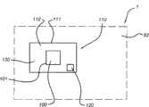
图1示意性地示出根据本发明的实施例的光刻设备1。所述设备1包括用于产生辐射的源SO;照射系统(照射器)IL,配置用于调节来自所接收到的从源SO发出的辐射的辐射束B(例如,紫外(UV)辐射或极紫外(EUV)辐射)。所述源SO可以被设置成分立的单元。支撑件(例如掩模台)MT,被配置以支撑图案形成装置(例如掩模)MA并与配置用于根据确定的参数精确地定位图案形成装置MA的第一定位装置PM相连。衬底台(例如晶片台)WT,被配置以保持衬底(例如涂覆有抗蚀剂的晶片)W,并与配置用于根据确定的参数精确地定位衬底W的第二定位装置PW相连。投影系统(例如折射式投影透镜系统)PS被配置用于将由图案形成装置MA赋予辐射束B的图案投影到衬底W的目标部分C(例如包括一根或多根管芯)上。Fig. 1 schematically shows a
所述照射系统可以包括各种类型的光学部件,例如折射型、反射型、磁性型、电磁型、静电型或其它类型的光学部件、或其任意组合,以引导、成形、或控制辐射。The illumination system may include various types of optical components, such as refractive, reflective, magnetic, electromagnetic, electrostatic, or other types of optical components, or any combination thereof, to direct, shape, or control radiation.
所述支撑件支撑图案形成装置(例如承载其重量)。支撑件以依赖于图案形成装置的方向、光刻设备的设计以及诸如图案形成装置是否保持在真空环境中等其它条件的方式保持图案形成装置。支撑件可以采用机械的、真空的、静电的或其它夹持技术来保持图案形成装置。所述支撑件可以是框架或台,例如,其可以根据需要成为固定的或可移动的。所述支撑件可以确保图案形成装置位于所需的位置上(例如相对于投影系统)。在这里任何使用的术语“掩模板”或“掩模”都可以认为与更上位的术语“图案形成装置”同义。The support supports the patterning device (eg carries its weight). The support holds the patterning device in a manner that depends on the orientation of the patterning device, the design of the lithographic apparatus, and other conditions such as whether the patterning device is held in a vacuum environment. The support may employ mechanical, vacuum, electrostatic or other clamping techniques to hold the patterning device. The support may be a frame or a table, for example, which may be fixed or movable as required. The support may ensure that the patterning device is in a desired position (eg relative to the projection system). Any use of the terms "reticle" or "mask" herein may be considered synonymous with the more general term "patterning device."
这里所使用的术语“图案形成装置”应该被广义地理解为表示能够用于将图案在辐射束的横截面上赋予辐射束、以便在衬底的目标部分上形成图案的任何装置。应当注意,被赋予辐射束的图案可能不与在衬底的目标部分上的所需图案完全相符(例如如果该图案包括相移特征或所谓辅助特征)。通常,被赋予辐射束的图案将与在目标部分上形成的器件中的特定的功能层相对应,例如集成电路。The term "patterning device" as used herein should be broadly construed to mean any device that can be used to impart a radiation beam with a pattern in its cross-section so as to form a pattern in a target portion of a substrate. It should be noted that the pattern imparted to the radiation beam may not exactly correspond to the desired pattern on the target portion of the substrate (eg if the pattern includes phase shifting features or so-called assist features). Typically, the pattern imparted to the radiation beam will correspond to a specific functional layer in a device formed on the target portion, such as an integrated circuit.
图案形成装置可以是透射式的或反射式的。图案形成装置的示例包括掩模、可编程反射镜阵列以及可编程液晶显示(LCD)面板。掩模在光刻术中是公知的,并且包括诸如二元掩模类型、交替型相移掩模类型、衰减型相移掩模类型和各种混合掩模类型之类的掩模类型。可编程反射镜阵列的示例采用小反射镜的矩阵布置,每一个小反射镜可以独立地倾斜,以便沿不同方向反射入射的辐射束。所述已倾斜的反射镜将图案赋予由所述反射镜矩阵反射的辐射束。The patterning device can be transmissive or reflective. Examples of patterning devices include masks, programmable mirror arrays, and programmable liquid crystal display (LCD) panels. Masks are well known in lithography and include mask types such as binary, alternating phase-shift, attenuated phase-shift, and various hybrid mask types. An example of a programmable mirror array employs a matrix arrangement of small mirrors, each of which can be independently tilted to reflect an incident radiation beam in different directions. The tilted mirrors impart a pattern to the radiation beam reflected by the mirror matrix.
这里使用的术语“投影系统”应该广义地解释为包括任意类型的投影系统,包括折射型、反射型、反射折射型、磁性型、电磁型和静电型光学系统、或其任意组合,如对于所使用的曝光辐射所适合的、或对于诸如使用浸没液或使用真空之类的其他因素所适合的。这里使用的术语“投影透镜”可以认为是与更上位的术语“投影系统”同义。As used herein, the term "projection system" should be broadly interpreted to include any type of projection system, including refractive, reflective, catadioptric, magnetic, electromagnetic, and electrostatic optical systems, or any combination thereof, as for all as appropriate for the exposure radiation used, or for other factors such as the use of immersion liquid or the use of a vacuum. The term "projection lens" as used herein may be considered synonymous with the more general term "projection system".
如这里所示的,所述设备是反射型的(例如,采用反射式掩模)。替代地,所述设备可以是透射型的(例如,采用透射式掩模)。As shown here, the device is reflective (eg, employs a reflective mask). Alternatively, the device may be transmissive (eg, employing a transmissive mask).
所述光刻设备可以是具有两个(双台)或更多衬底台(和/或两个或更多的掩模台)的类型。在这种“多台”机器中,可以并行地使用附加的台,或可以在一个或更多个台上执行预备步骤的同时,将一个或更多个其它台用于曝光。The lithographic apparatus may be of the type with two (dual-stage) or more substrate stages (and/or two or more mask stages). In such "multi-stage" machines, additional tables may be used in parallel, or one or more other tables may be used for exposure while preparatory steps are being performed on one or more tables.
光刻设备也可以是以下类型的,其中衬底的至少一部分可以被具有相对高折射率的液体(例如水)所覆盖,以填充投影系统和衬底之间的空间。浸没液体也可以施加到光刻设备中的其它空间,例如施加到掩模和投影系统之间。浸没技术可用于增加投影系统的数值孔径在本领域是公知的。此处所使用的术语“浸没”并不意味着诸如衬底等结构必须浸没在液体中,而仅仅意味着在曝光期间液体处于例如投影系统和衬底之间。The lithographic apparatus may also be of the type in which at least a portion of the substrate may be covered with a relatively high refractive index liquid, such as water, to fill the space between the projection system and the substrate. The immersion liquid can also be applied to other spaces in the lithographic apparatus, for example between the mask and the projection system. It is well known in the art that immersion techniques can be used to increase the numerical aperture of projection systems. The term "immersion" as used herein does not mean that the structure such as the substrate is necessarily submerged in the liquid, but only that the liquid is between eg the projection system and the substrate during exposure.
参照图1,所述照射器IL接收从辐射源SO发出的辐射束。该源和所述光刻设备可以是分立的实体(例如当该源为准分子激光器时)。在这种情况下,不会将该源考虑成形成光刻设备的一部分,并且通过包括例如合适的定向反射镜和/或扩束器的束传递系统的帮助,将所述辐射从所述源SO传到所述照射器IL。在其它情况下,所述源可以是所述光刻设备的组成部分(例如当所述源是汞灯时)。可以将所述源SO和所述照射器IL、以及如果需要时设置的所述束传递系统一起称作辐射系统。Referring to FIG. 1 , the illuminator IL receives a radiation beam emitted from a radiation source SO. The source and the lithographic apparatus may be separate entities (eg when the source is an excimer laser). In this case, the source is not considered to form part of the lithographic apparatus and the radiation is diverted from the source to SO passes to the illuminator IL. In other cases, the source may be an integral part of the lithographic apparatus (eg when the source is a mercury lamp). The source SO and the illuminator IL, together with the beam delivery system if required, may be referred to as a radiation system.
所述照射器IL可以包括配置用于调整所述辐射束的角强度分布的调整装置。通常,可以对所述照射器的光瞳平面中的强度分布的至少所述外部和/或内部径向范围(一般分别称为σ-外部和σ-内部)进行调整。此外,所述照射器IL可以包括各种其它部件,例如积分器和聚光器。可以将所述照射器用于调节所述辐射束,以在其横截面中具有所需的均匀性和强度分布。The illuminator IL may comprise adjustment means configured to adjust the angular intensity distribution of the radiation beam. Typically, at least the outer and/or inner radial extent (commonly referred to as σ-outer and σ-inner, respectively) of the intensity distribution in the pupil plane of the illuminator can be adjusted. In addition, the illuminator IL may include various other components such as integrators and condensers. The illuminator can be used to condition the radiation beam to have a desired uniformity and intensity distribution in its cross-section.
所述辐射束B入射到保持在支撑件(例如,掩模台)MT上的所述图案形成装置(例如,掩模MA)上,并且通过所述图案形成装置来形成图案。已经穿过掩模MA之后,所述辐射束B通过投影系统PS,所述投影系统PS将所述束投影到所述衬底W的目标部分C上。通过第二定位装置PW和位置传感器IF2(例如,干涉仪器件、线性编码器或电容传感器)的帮助,可以精确地移动所述衬底台WT,例如以便将不同的目标部分C定位于所述辐射束B的路径中。类似地,例如在从掩模库的机械获取之后,或在扫描期间,可以将所述第一定位装置PM和另一个位置传感器IF1(例如干涉仪器件、线性编码器或电容传感器)可以用于相对于所述辐射束B的路径精确地定位掩模MA。通常,可以通过形成所述第一定位装置PM的一部分的长行程模块(粗定位)和短行程模块(精定位)的帮助来实现掩模台MT的移动。类似地,可以采用形成所述第二定位装置PW的一部分的长行程模块和短行程模块来实现所述衬底台WT的移动。在步进机的情况下(与扫描器相反),所述掩模台MT可以仅与短行程致动器相连,或可以是固定的。可以使用掩模对准标记M1、M2和衬底对准标记P1、P2来对准掩模MA和衬底W。尽管所示的衬底对准标记占据了专用目标部分,但是它们可以位于目标部分之间的空间(这些公知为划线对准标记)中。类似地,在将多于一个的管芯设置在掩模MA上的情况下,所掩模对准标记可以位于所述管芯之间。The radiation beam B is incident on the patterning device (eg mask MA) held on a support (eg mask table) MT and is patterned by the patterning device. After having passed through the mask MA, the radiation beam B passes through a projection system PS which projects the beam onto a target portion C of the substrate W. With the help of a second positioner PW and a position sensor IF2 (e.g. an interferometric device, a linear encoder or a capacitive sensor), the substrate table WT can be moved precisely, for example in order to position different target portions C on the In the path of radiation beam B. Similarly, the first positioner PM and a further position sensor IF1 (such as an interferometric device, linear encoder or capacitive sensor) can be used for The mask MA is precisely positioned relative to the path of said radiation beam B. Typically, the movement of the mask table MT can be achieved with the aid of a long-stroke module (coarse positioning) and a short-stroke module (fine positioning) forming part of said first positioner PM. Similarly, movement of the substrate table WT may be achieved using a long-stroke module and a short-stroke module forming part of the second positioner PW. In the case of a stepper (as opposed to a scanner), the mask table MT may be connected to a short-stroke actuator only, or may be fixed. Mask MA and substrate W may be aligned using mask alignment marks M1 , M2 and substrate alignment marks P1 , P2 . Although the substrate alignment marks are shown occupying dedicated target portions, they may be located in spaces between target portions (these are known as scribe line alignment marks). Similarly, where more than one die is disposed on the mask MA, the mask alignment marks may be located between the dies.
可以将所述设备用于以下模式中的至少一种中:The device can be used in at least one of the following modes:
a.在步进模式中,在将掩模台MT和衬底台WT保持为基本静止的同时,将赋予所述辐射束的整个图案一次投影到目标部分C上(即,单一的静态曝光)。然后将所述衬底台WT沿X和/或Y方向移动,使得可以对不同目标部分C曝光。在步进模式中,曝光场的最大尺寸限制了在单一的静态曝光中成像的所述目标部分C的尺寸。a. In step mode, while holding the mask table MT and substrate table WT substantially stationary, the entire pattern imparted to the radiation beam is projected onto the target portion C at once (i.e., a single static exposure) . The substrate table WT is then moved in the X and/or Y direction so that different target portions C can be exposed. In step mode, the maximum size of the exposure field limits the size of the target portion C imaged in a single static exposure.
b.在扫描模式中,在对掩模台MT和衬底台WT同步地进行扫描的同时,将赋予所述辐射束的图案投影到目标部分C上(即,单一的动态曝光)。衬底台WT相对于掩模台MT的速度和方向可以通过所述投影系统PS的(缩小)放大率和图像反转特征来确定。在扫描模式中,曝光场的最大尺寸限制了单一动态曝光中所述目标部分的宽度(沿非扫描方向),而所述扫描运动的长度确定了所述目标部分的高度(沿所述扫描方向)。b. In scan mode, the pattern imparted to the radiation beam is projected onto the target portion C while the mask table MT and substrate table WT are scanned synchronously (ie a single dynamic exposure). The velocity and direction of the substrate table WT relative to the mask table MT can be determined by the (de-)magnification and image inversion characteristics of the projection system PS. In scanning mode, the maximum size of the exposure field limits the width of the target portion (along the non-scanning direction) in a single dynamic exposure, while the length of the scanning motion determines the height of the target portion (along the scanning direction). ).
c.在另一个模式中,将用于保持可编程图案形成装置的掩模台MT保持为基本静止,并且在对所述衬底台WT进行移动或扫描的同时,将赋予所述辐射束的图案投影到目标部分C上。在这种模式中,通常采用脉冲辐射源,并且在所述衬底台WT的每一次移动之后、或在扫描期间的连续辐射脉冲之间,根据需要更新所述可编程图案形成装置。这种操作模式可易于应用于利用可编程图案形成装置(例如,如上所述类型的可编程反射镜阵列)的无掩模光刻术中。c. In another mode, the mask table MT holding the programmable patterning device is held substantially stationary, and while the substrate table WT is being moved or scanned, the radiation beam imparted The pattern is projected onto the target portion C. In this mode, a pulsed radiation source is typically employed and the programmable patterning device is updated as required after each movement of the substrate table WT, or between successive radiation pulses during scanning. This mode of operation is readily applicable in maskless lithography using programmable patterning devices, such as programmable mirror arrays of the type described above.
也可以采用上述使用模式的组合和/或变体,或完全不同的使用模式。Combinations and/or variations of the above described modes of use, or entirely different modes of use may also be employed.
在上下文允许的情况下,术语“透镜”可以表示各种类型的光学部件中的任意一个或它们的组合,包括折射式、反射式、磁性式、电磁式和静电式光学部件。The term "lens", where the context permits, may refer to any one or combination of various types of optical components, including refractive, reflective, magnetic, electromagnetic, and electrostatic optical components.
此处使用的术语“辐射”和“束”包括全部类型的电磁辐射,包括紫外(UV)辐射(例如具有365、248、193、157或126nm的波长λ)和极紫外(EUV或软X射线)辐射(例如具有在5-20nm范围内的波长,例如约13.5nm)以及粒子束(例如离子束或电子束)。通常,具有在约780-3000nm(或更大)之间的波长的辐射被认为是红外(IR)辐射。UV表示具有约100-400nm的波长的辐射。在光刻术中,通常还可以应用由汞放电灯产生的波长:G线436nm、H线405nm和/或I线365nm。VUV是真空UV(即被空气吸收的UV)且表示约100-200nm的波长。DUV是深UV,且由准分子激光器产生的例如126-248nm的波长的DUV通常被用于光刻术。本领域技术人员应当理解,具有在例如5-20nm范围内的波长的辐射与至少一部分在5-20nm范围内的特定波长带的辐射相关。The terms "radiation" and "beam" as used herein include all types of electromagnetic radiation, including ultraviolet (UV) radiation (e.g. having a wavelength λ of 365, 248, 193, 157 or 126 nm) and extreme ultraviolet (EUV or soft X-ray ) radiation (eg having a wavelength in the range of 5-20 nm, eg about 13.5 nm) and particle beams (eg ion beams or electron beams). Generally, radiation having a wavelength between about 780-3000 nm (or greater) is considered infrared (IR) radiation. UV denotes radiation having a wavelength of about 100-400 nm. In photolithography, wavelengths generated by mercury discharge lamps are generally also applicable: G-line 436 nm, H-line 405 nm and/or I-line 365 nm. VUV is vacuum UV (ie, UV absorbed by air) and refers to wavelengths of about 100-200 nm. DUV is deep UV, and DUV at wavelengths such as 126-248 nm generated by excimer lasers is commonly used in photolithography. A person skilled in the art will understand that radiation having a wavelength in the range of, for example, 5-20 nm is associated with at least a portion of radiation of a specific wavelength band in the range of 5-20 nm.
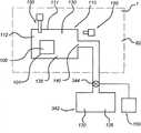
图2更详细地显示出投影设备1,包括辐射系统42、照射光学装置单元44和投影系统PS。辐射系统42包括可以由放电等离子体形成的照射源SO。EUV辐射可以由气体或蒸汽来产生,例如Xe气体、Li蒸汽或Sn蒸汽,其中非常热的等离子体被产生以发射在EUV范围的电磁光谱中的辐射。通过例如放电产生至少部分地电离的等离子体,来形成非常热的等离子体。对于有效地产生辐射来说,可能需要例如分压为10Pa的Xe、Li、Sn蒸汽或任何其它的适合的气体或蒸汽。在实施例中,应用锡(Sn)源作为EUV源。由辐射源SO发射出的辐射从源腔47经由可选择的气体阻挡件或污染物阱49(也被描述为污染物阻挡件或翼片阱)传送至收集器腔48中,所述气体阻挡件或污染物阱49被定位在源腔47中的开口中或其后面。污染物阱49可以包括通道结构。污染物阱49还可以包括气体阻挡件或者气体阻挡件和通道结构的组合。在此处进一步描述的污染物阱或污染物阻挡件49至少包括如在本领域中所知的通道结构。Fig. 2 shows the
收集器腔48包括可以由掠入射收集器形成的辐射收集器50(在此处也被表示为收集器反射镜)。辐射收集器50具有上游辐射收集器侧50a和下游辐射收集器侧50b。通过收集器50的辐射可以被反射远离光栅光谱滤光片51,以被聚焦到在收集器腔48中的孔径处的虚源点52上。来自收集器腔48的辐射束56在照射光学装置单元44中被经由正入射反射器53、54反射到定位到掩模板或掩模台MT上的掩模板或掩模上。形成了图案化的束57,该图案化的束57在投影系统PS中被经由反射元件58、59成像到晶片平台或衬底台WT上。通常在照射光学装置单元44和投影系统PS中可以出现比所显示的元件更多的元件。光栅光谱滤光片51可以依赖于光刻设备的类型可选择地出现。此外,可能具有比图中显示的反射镜更多的反射镜,例如可能具有比反射镜58、59多1-4个的反射性元件。辐射收集器50是从现有技术已知的。The
除了掠入射反射镜作为收集器反射镜50之外,也可以应用正入射收集器。如在此处在实施例中更加描述的收集器反射镜50是具有反射器142、143和146的巢状收集器,且如示意性地描绘出的以及其它的,图2在此处被进一步地用作为收集器(或收集器反射镜)的例子。因此,在可应用的情况下,用作掠入射收集器的收集器反射镜50通常可以解释为收集器,在特定的实施例中也可被解释为正入射收集器。Instead of grazing incidence mirrors as collector mirrors 50, normal incidence collectors can also be used.
此外,除了光栅51之外,如在图2中示意性地显示地,也可以采用透射式光学滤光片,或在实施例中可以根本不使用滤光片51。对于EUV辐射是透射的而对于UV辐射是较不透射的或甚至基本上吸收UV辐射的光学滤光片在本领域中是已知的。“光栅光谱纯度滤光片”在此处被表示成“光谱纯度滤光片”,其包括光栅或透射滤光片。虽然没有在图2中示出,但是所包含的可选择的光学元件可以是EUV透射光学滤光片(例如被布置在收集器反射镜50的上游)或在照射单元44和/或投影系统PS中的光学EUV透射滤光片。Furthermore, instead of the grating 51 , as schematically shown in FIG. 2 , a transmissive optical filter may also be employed, or in an embodiment no
在实施例(也可参见上文)中,辐射收集器50可以是掠入射收集器。收集器50被沿着光轴O对准。源SO或其图像被定位在光轴O上。辐射收集器50可以包括反射器142、143、146(也被称为包括多个沃尔特(Wolter)类型的反射器的Wolter类型反射器)。有时,它们也被称为壳(shell)。这些反射器(或壳)142、143、146可以巢状的且关于光轴O是旋转对称的。在图2(以及其它图中),内反射器由附图标记142表示,中间反射器由附图标记143表示,以及外反射器由附图标记146表示。辐射收集器50包围特定的体积,即在外反射器146内的体积。典型地,尽管可以出现小的开口,但是在外反射器146内的这一体积是圆周地密闭的。所有的反射器142、143和146包括多个表面,所述反射器的表面的至少一部分包括一反射层或多个反射层。因此,反射器142、143和146(可以设置更多的反射器,且具有多于3个反射器或壳的辐射收集器(也被称为收集器反射镜)50的实施例也被包含于其中)至少一部分被设计用于反射和收集来自源SO的EUV辐射,且反射器的至少一部分可以不被设计用于反射和收集EUV辐射。例如,反射器的后侧的至少一部分可以不被设计用于反射和收集EUV辐射。上述后一部分也可以被称为后侧。另外地,在这些反射层的表面上可以具有用于保护的或用作设置在反射层表面的至少一部分上的光学滤光片的覆盖层。In an embodiment (see also above), the
辐射收集器50通常放置在源SO或源SO的像的邻近区域内。每个反射器142、143、146可以包括至少两个相邻的反射表面,与更靠近源SO的反射表面相比,更远离源SO的反射表面被以与光轴O成更小的角度设置。这样,掠入射收集器50被配置以产生沿着光轴O传播的(E)UV辐射束。至少两个反射器可以被基本上同轴地设置且关于光轴O基本上旋转对称地延伸。应当理解,辐射收集器50可以在外反射器146的外表面上具有另外的特征或围绕外反射器146具有另外的特征,例如保护性保持器、加热器等。附图标记180表示两个反射器之间的空间,例如反射器142和143之间的空间。每一反射器142、143、146可以包括至少两个相邻的反射表面,与更靠近源SO的反射表面相比,更远离源SO的反射表面被以与光轴O成更小的角度设置。这样,掠入射反射器50被配置以产生沿着光轴O传播的(E)UV辐射束。至少两个反射器可以被基本上同轴地设置且关于光轴O基本上旋转对称地延伸。应当理解,辐射收集器50可以在外反射器146的外表面上具有另外的特征或围绕外反射器146具有另外的特征,例如保护性保持器、加热器等。附图标记180表示两个反射器之间的空间,例如反射器142和143之间的空间。The
图3示意性地示出被光刻设备1包含的保护性外罩110。因为可以在光刻设备的任意位置应用磁体,所以光刻设备1以虚线画出的外框表示。附图标记82表示光刻设备内部的一部分,其中布置有磁体100和保护性外罩110。附图标记82表示被光刻设备1所包含的保护性外罩110的外部。FIG. 3 schematically shows a
注意到,术语“磁体”和“外罩”也可以分别涉及多个磁体和多个外罩。为了简明起见,在此处仅示意性示出了在一个保护性外罩110中仅有一个磁体100,但是本发明不限于这样的配置。Note that the terms "magnet" and "housing" may also refer to a plurality of magnets and a plurality of housings, respectively. For simplicity, only one
外罩110具有壁111,从而将磁体100包围在体积112中。磁体100的体积通常将小于保护性外罩110的体积112(即被保护性外罩110包围的体积)。外罩体积112和磁体100的体积的比可以在约1.1-20范围内,或在约1.1-10范围内。The
外罩体积112可以包括气体130。该气体可以是非包含氢的气体。在实施例中,外罩体积112中的压强在真空范围内,例如在约0.001-0.1Pa的范围内。外罩体积112可以进一步包括氢气吸气剂120,诸如例如La、Nd、Sm、Gd等的稀土金属。外罩110内的压强也可以更大。在实施例中,外罩110内的压强可以在约0.001Pa至大于气体环境压强的范围内,例如达到约6巴。
这样,光刻设备1包括磁体100,该磁体110被包含在保护性外罩110内,且保护性外罩110被布置以保护磁体100不与包含H2或包含H原子的气体接触,所述气体可能出现在光刻设备内部82(的至少一部分)内。因为观察到H2和/或H可能侵蚀磁体100,尤其是包括诸如Sm或La等稀土元素的磁体,保护性外罩110可以被布置以保护磁体100不与可能出现在光刻设备1(例如光刻设备内部82的一部分)中的包含H2或包含H原子的气体接触。这可以为磁体100提供更长寿命和/或更好的操作(即保护磁体100)。外罩110的使用可以防止或减小H根和/或H2的侵蚀,由附图标记101表示的磁体的表面可以被保护以防止H2和/或H原子(或H根)的侵蚀。Thus, the
在特定的实施例中,非包含氢的气体包括磁体表面修饰气体。适合的磁体表面修饰气体尤其是包含O2的气体,例如O2或空气或水蒸汽。这样的包含O2的气体可能导致侵蚀磁体表面101,从而形成氧化层。这样的氧化层可以进一步保护磁体100免受H和/或H2的侵蚀。当例如包含O2的气体的磁体表面修饰气体出现在外罩110中时,在表面101处的反应可能是氧化性的。In certain embodiments, the non-hydrogen-containing gas includes a magnet surface modifying gas. Suitable magnet surface modifying gases are especiallyO2 -containing gases, such asO2 or air or water vapour. Such O2 -containing gases may cause erosion of the
在图4中,示意性地示出了一实施例,其中保护性外罩110包括非包含氢的气体130。这一气体可以具有磁体表面修饰功能,因而是磁体表面修饰气体135,而且还可以是不具有修饰表面的能力的另一种气体。在图4中非包含氢的气体用附图标记130表示。图4示意性示出了一实施例,在该实施例中,非包含氢的气体130可以是用附图标记135表示的磁体表面修饰气体。In FIG. 4 , an embodiment is schematically shown wherein the
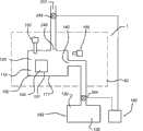
在实施例中,保护性外罩110还包括用于非包含氢的气体130的入口140。通过入口140,可以由气体源342提供气体130。为此目的,泵或阀344可以将气体130引入到保护性外罩110中。再者,非包含氢的气体130可以包括磁体表面修饰气体135(在此处被示意性地示出的)。在实施例中,可以通过控制器160来控制泵或阀344,该控制器160以例如被布置以在保护性外罩110中保持气体130(包括可选择地包含磁体表面修饰气体135)的预定压强。为此目的,控制器160还可以接收传感器150的输入信号,在实施例中,传感器150被布置成测量保护性外罩110内的气体压强。可替代地,或与在实施例中被布置成测量保护性外罩110内的气体压强的传感器150结合,传感器150(还)可以被布置成感测在保护性外罩110内H2的存在和/或测量H2的压强(分压)。在实施例中,控制器150可以被布置成对保护性外罩110内的非包含氢的气体130的预定压强进行控制和/或可以被布置以感测在保护性外罩110内H2的存在和/或测量H2的压强(分压)。这样,例如保护性外罩110内的气体环境可以被保持处于高于保护性外罩的外部(即在光刻设备体积82中)的压强的压强上。如上文所提及的,在实施例中,非包含氢的气体130还可以包括磁体表面修饰气体135。内部保护性外罩的压强与保护性外罩110的外部的压强的比可以高于约1,例如在约1.01-10000的范围内,或在约1.1-10000的范围内。In an embodiment, the
在实施例中,保护性外罩110或更精确地是光刻设备1可以还包括检测器155,该检测器155被布置以检测气体从保护性外罩110的泄漏。检测器155可以被布置在保护性外罩110的外面,用以测量来自保护性外罩110的气体是否泄漏到保护性外罩110的外部空间82。检测器155可以例如是质谱仪。为了便于检测,非氢气体或磁体表面修饰气体可以包括被选择以便于检测的气体,诸如例如Ne或另一种惰性气体,其可能利用化学方法或光谱方法或通过质量选择检测器等被相对容易地检测。控制器160还可以被布置以接收来自传感器155的信号,且基于这一信号控制非包含氢的气体130到保护性外罩110的输入和/或非包含氢的气体130在保护性外罩110内的压强。因此,这样还提供了一种方法,所述方法包括:将非包含氢的气体130馈送至保护性外罩110内。如上所述,在实施例中,非包含氢的气体130包括磁体表面修饰气体135。In an embodiment, the
在另一实施例中,形成了大致动态的情形或实施例,其中非包含氢的气体130流过保护性外罩110。在图5中示意性地示出了这样的实施例。在此处,保护性外罩110还包括用于非包含氢的气体130的入口140和出口240。光刻设备1还可以包括控制器160,该控制器160被布置以控制非包含氢的气体130的通过保护性外罩110的至少一部分的流。控制器160可以被布置以控制所述流的体积流量、所述流的质量流量或上述两者。在实施例中,气体从气体源342流过保护性外罩110的至少一部分,且在出口240离开保护性外罩110。光刻设备1可以进一步包括泵或阀244,所述泵或阀244被布置以允许气体从保护性外罩110经由出口240逃逸至排放装置242。在实施例中,控制器160可以被布置以控制阀或泵344和/或阀或泵244,从而允许在贯穿的保护性外罩110中分别保持气体130的预定的压强或流量或者压强和流量两者。再者,可以应用传感器150和/或传感器155。因此,保护性方法可以包括使得非包含氢的气体130流过外罩110的至少一部分。如上所述,在实施例中,非包含氢的气体130包括磁体表面修饰气体135。内部的保护性外罩的压强与保护性外罩110的外部的压强的比可以大于约1,例如在约1.01-10000的范围内,或在约1.1-10000的范围内。这样,可以建立净化流配置,使得在磁体100附近的氢气含量可以被限制。In another embodiment, a substantially dynamic situation or embodiment is created wherein the
此处描述的实施例提供了具有特定的磁体保护的光刻设备1。光刻设备1包括被包含在保护性外罩110内的磁体100,所述保护性外罩110被布置以保护磁体100不与包含H2的或包含H原子的气体接触。外罩还可以包含氢气吸气剂120(在图3中显示的),和/或在实施例中包含磁体表面修饰气体135,和/或包含另一种非包含氢的气体130。另外,非包含氢的气流可以被提供或磁体表面修饰气流可以被提供穿过保护性外罩110的至少一部分。The embodiments described here provide a
在实施例中,提供了一种用于保护光刻设备1中的磁体100的方法,其中所述方法包括:将磁体100包含到保护性外罩110内,该保护性外罩110被布置以保护磁体100不与可能出现在外罩外部82中的包含H2或包含H原子的气体接触,例如通过使用上文和在此处进一步描述的保护性外罩110的实施例。这样的方法可以还包括一个或更多的保护性措施,所述保护性措施被从由(a)提供氢气吸气剂120至保护性外罩110、(b)分别将非包含氢的气体130馈送或流动至保护性外罩110或到保护性外罩110中和(c)分别地将磁体表面修饰气体135馈送或流动至保护性外罩110或到保护性外罩110中的步骤构成的组中选出。在实施例中,内部的保护性外罩的压强与保护性外罩110的外部的压强的比可以被保持大于约1,例如在约1.01-10000的范围内,或在约1.1-10000的范围内。这样,非包含氢的气体130(包括磁体表面修饰气体135)的存在可以有效地削减或甚至防止氢根和/或氢气被引入到保护性外罩110内(其中氢根和/或氢气可以存在于包含保护性外罩110的光刻设备中)。In an embodiment there is provided a method for protecting a
在实施例中,磁体是包含稀土(元素)的磁体,例如包含Nd或Sm的磁体。In an embodiment, the magnet is a rare earth (element) containing magnet, such as a Nd or Sm containing magnet.
此处公开的实施例还提供了使用光刻设备1的器件制造方法,其中光刻设备1包括磁体100,且所述方法包括:将磁体100包含到保护性外罩110内,该保护性外罩110被布置以保护磁体100不与可能在外罩外部82中出现的包含H2的或包含H原子的气体接触。Embodiments disclosed herein also provide a method of device fabrication using a
附图示出了多个可能的实施例,本发明不限于此。磁体100可以被从氢气吸气剂120、非包含氢的气体130和磁体表面修饰气体135的组中选择的一种或更多种磁体保护剂保护,且当使用气体时,保护性外罩可以被布置以提供非包含氢的气体130的流和/或磁体表面修饰气体135的流。The figures show a number of possible embodiments, to which the invention is not limited. The
尽管在本文中可以做出具体的参考,将所述光刻设备用于制造IC,但应当理解这里所述的光刻设备可以有其他的应用,例如,集成光学系统、磁畴存储器的引导和检测图案、平板显示器、包括液晶显示器(LCD)的平板显示器、薄膜磁头等的制造。本领域技术人员应该理解的是,在这种替代应用的情况中,可以将其中使用的任意术语“晶片”或“管芯”分别认为是与更上位的术语“衬底”或“目标部分”同义。这里所指的衬底可以在曝光之前或之后进行处理,例如在轨道(一种典型地将抗蚀剂层涂到衬底上,并且对已曝光的抗蚀剂进行显影的工具)、量测工具和/或检验工具中。在可应用的情况下,可以将此处公的开内容应用于这种和其它衬底处理工具中。另外,所述衬底可以处理一次以上,例如以便产生多层IC,使得这里使用的所述术语“衬底”也可以表示已经包含多个已处理层的衬底。Although specific reference may be made herein to the use of the lithographic apparatus in the fabrication of ICs, it should be understood that the lithographic apparatus described herein may have other applications, such as integrated optical systems, magnetic domain memory guidance and Manufacture of inspection patterns, flat panel displays, flat panel displays including liquid crystal displays (LCD), thin film magnetic heads, etc. It will be understood by those skilled in the art that, in the case of this alternate application, any term "wafer" or "die" used therein may be considered to be synonymous with the more general term "substrate" or "target portion", respectively. synonymous. The substrate referred to here can be processed before or after exposure, such as in a track (a tool that typically applies a layer of resist to a substrate and develops the exposed resist), metrology tools and/or inspection tools. Where applicable, the disclosure disclosed herein may be applied to this and other substrate processing tools. In addition, the substrate may be processed more than once, for example in order to produce a multilayer IC, so that the term "substrate" as used herein may also denote a substrate that already contains a plurality of processed layers.
尽管以上已经做出了具体的参考,在光学光刻的情况中使用本发明的实施例,但应该理解的是,本发明可以用于其他应用中,例如压印光刻,并且只要情况允许,不局限于光学光刻。在压印光刻中,图案形成装置中的拓扑限定了在衬底上产生的图案。可以将所述图案形成装置的拓扑印刷到提供给所述衬底的抗蚀剂层中,在其上通过施加电磁辐射、热、压力或其组合来使所述抗蚀剂固化。在所述抗蚀剂固化之后,所述图案形成装置从所述抗蚀剂上移走,并在抗蚀剂中留下图案。Although specific reference has been made above to the use of embodiments of the invention in the context of optical lithography, it should be understood that the invention may be used in other applications, such as imprint lithography, and as far as the circumstances warrant, Not limited to optical lithography. In imprint lithography, the topology in the patterning device defines the pattern produced on the substrate. The topography of the patterning device may be printed into a resist layer provided to the substrate whereupon the resist is cured by application of electromagnetic radiation, heat, pressure or a combination thereof. After the resist is cured, the patterning device is removed from the resist, leaving a pattern in the resist.
尽管以上已经描述了本发明的特定的实施例,但是应该理解的是本发明可以以与上述不同的形式实现。例如,本发明可以采取包含用于描述上述公开的方法的一个或更多个机器可读指令序列的计算机程序的形式,或者采取具有在其中存储的这种计算机程序的数据存储介质的形式(计算机可读介质,例如,半导体存储器、磁盘或光盘)。这种计算机程序可以用于控制沉积物的移除、控制压强等。While specific embodiments of the invention have been described above, it should be understood that the invention may be embodied in forms other than those described above. For example, the invention may take the form of a computer program containing one or more sequences of machine-readable instructions for describing the methods disclosed above, or a data storage medium having such a computer program stored therein (computer readable medium such as semiconductor memory, magnetic disk or optical disk). Such a computer program can be used to control the removal of deposits, control pressure, and the like.
上文的描述的意图是说明性的,而不是限制性的。因此,本领域技术人员应当明白可以在不背离下文所阐述的权利要求的范围的情况下对如所描述的本发明进行修改。动词“包括”的使用和其变形不排除出现除了权利要求中所描述的之外的元件或步骤。在元件之前的“一”或“一个”不排除出现多个这样的元件。The description above is intended to be illustrative, not restrictive. Accordingly, it will be apparent to those skilled in the art that modifications may be made in the invention as described without departing from the scope of the claims hereinafter set forth. Use of the verb "to comprise" and its conjugations does not exclude the presence of elements or steps other than those stated in a claim. "A" or "an" preceding an element does not exclude the presence of a plurality of such elements.
本发明不限于光刻设备的应用或用于如在实施例中描述的光刻设备。另外,附图通常只包括理解本发明所必需的元件和特征。除此之外,光刻设备的附图是示意性的且不是按比例绘制的。本发明不限制于在示意性附图中显示的这些元件(例如在示意性附图中绘制的反射镜的数量)。此外,本发明不限于关于图1描述的光刻设备。可以将关于辐射收集器所描述的本发明用于(其它的)多层的、掠入射反射镜或其它的光学元件。应当理解,可以组合上文描述的实施例。The invention is not limited to application to lithographic apparatus or to a lithographic apparatus as described in the examples. In addition, the drawings generally only include elements and features that are necessary to understand the invention. Otherwise, the drawings of the lithographic apparatus are schematic and not drawn to scale. The invention is not limited to the elements shown in the schematic drawings (for example the number of mirrors drawn in the schematic drawings). Furthermore, the invention is not limited to the lithographic apparatus described with respect to FIG. 1 . The invention described in relation to radiation collectors can be used for (other) multilayer, grazing incidence mirrors or other optical elements. It should be understood that the embodiments described above may be combined.
Claims (14)
Applications Claiming Priority (3)
| Application Number | Priority Date | Filing Date | Title |
|---|---|---|---|
| US6416508P | 2008-02-20 | 2008-02-20 | |
| US61/064,165 | 2008-02-20 | ||
| PCT/NL2009/050074WO2009104962A1 (en) | 2008-02-20 | 2009-02-19 | Lithographic apparatus comprising a magnet, method for the protection of a magnet in a lithographic apparatus and device manufacturing method |
Publications (2)
| Publication Number | Publication Date |
|---|---|
| CN101952780A CN101952780A (en) | 2011-01-19 |
| CN101952780Btrue CN101952780B (en) | 2013-01-23 |
Family
ID=40548602
Family Applications (1)
| Application Number | Title | Priority Date | Filing Date |
|---|---|---|---|
| CN2009801054379AActiveCN101952780B (en) | 2008-02-20 | 2009-02-19 | Lithographic apparatus including magnet, method of protecting magnet in lithographic apparatus, and device manufacturing method |
Country Status (7)
| Country | Link |
|---|---|
| US (1) | US8446560B2 (en) |
| JP (1) | JP2011512688A (en) |
| KR (1) | KR101583644B1 (en) |
| CN (1) | CN101952780B (en) |
| NL (1) | NL1036543A1 (en) |
| TW (1) | TWI422984B (en) |
| WO (1) | WO2009104962A1 (en) |
Families Citing this family (4)
| Publication number | Priority date | Publication date | Assignee | Title |
|---|---|---|---|---|
| DE102009008209A1 (en)* | 2009-02-10 | 2010-08-19 | Carl Zeiss Smt Ag | Actuator with at least one magnet for a projection exposure apparatus and projection exposure apparatus with a magnet and manufacturing method thereof |
| DE102009029282A1 (en)* | 2009-09-08 | 2011-03-24 | Carl Zeiss Smt Gmbh | Optical arrangement, in particular in a projection exposure apparatus for EUV lithography |
| JP2013519221A (en) | 2010-02-09 | 2013-05-23 | エーエスエムエル ネザーランズ ビー.ブイ. | Radiation source, lithographic apparatus, and device manufacturing method |
| KR101947049B1 (en)* | 2014-07-16 | 2019-05-16 | 에이에스엠엘 네델란즈 비.브이. | Lithographic apparatus and device manufacturing method |
Citations (4)
| Publication number | Priority date | Publication date | Assignee | Title |
|---|---|---|---|---|
| CN1440512A (en)* | 2000-03-31 | 2003-09-03 | 株式会社尼康 | Method and device for holding optical member, optical device, exposure apparatus and device manufacturing method |
| CN1441317A (en)* | 2002-02-01 | 2003-09-10 | Asml荷兰有限公司 | Method for producing photoetching device and equipment |
| CN1791793A (en)* | 2003-05-22 | 2006-06-21 | 皇家飞利浦电子股份有限公司 | Method and device for cleaning at least one optical component |
| EP1712955A2 (en)* | 2005-04-14 | 2006-10-18 | Canon Kabushiki Kaisha | Optical unit and exposure apparatus having the same |
Family Cites Families (13)
| Publication number | Priority date | Publication date | Assignee | Title |
|---|---|---|---|---|
| JP4567131B2 (en)* | 1999-12-27 | 2010-10-20 | 川惣電機工業株式会社 | Continuous temperature measuring device |
| JP5024531B2 (en)* | 2001-12-28 | 2012-09-12 | 信越化学工業株式会社 | How to use rare earth sintered magnets |
| EP1475668A1 (en)* | 2003-05-09 | 2004-11-10 | ASML Netherlands B.V. | Method of preparing components for a lithographic apparatus |
| US6853062B1 (en)* | 2003-12-02 | 2005-02-08 | Northrop Grumman Corporation | Single substrate hydrogen and microwave absorber for integrated microwave assembly and method of manufacturing same |
| JP4583048B2 (en)* | 2004-02-26 | 2010-11-17 | 信越化学工業株式会社 | Rare earth magnet sealed body and method of manufacturing IPM motor |
| JP4922638B2 (en)* | 2005-03-29 | 2012-04-25 | エーエスエムエル ネザーランズ ビー.ブイ. | Lithographic apparatus, seal, device manufacturing method, computer program, and data recording medium |
| US7367138B2 (en)* | 2005-10-11 | 2008-05-06 | Nikon Corporation | Devices and methods for thermophoretic and electrophoretic reduction of particulate contamination of lithographic reticles |
| US7541699B2 (en) | 2005-12-27 | 2009-06-02 | Asml Netherlands B.V. | Magnet assembly, linear actuator, planar motor and lithographic apparatus |
| JP4765747B2 (en)* | 2006-04-19 | 2011-09-07 | 日立金属株式会社 | Method for producing R-Fe-B rare earth sintered magnet |
| US7518128B2 (en) | 2006-06-30 | 2009-04-14 | Asml Netherlands B.V. | Lithographic apparatus comprising a cleaning arrangement, cleaning arrangement and method for cleaning a surface to be cleaned |
| JP4296442B2 (en)* | 2006-10-20 | 2009-07-15 | 信越化学工業株式会社 | Method for preventing hydrogen embrittlement of rare earth sintered magnets |
| EP1976344B1 (en) | 2007-03-28 | 2011-04-20 | Tokyo Institute Of Technology | Extreme ultraviolet light source device and extreme ultraviolet radiation generating method |
| US7985363B2 (en)* | 2008-02-12 | 2011-07-26 | Mack Molding Company | Method of encasing a magnet |
- 2009
- 2009-02-10NLNL1036543Apatent/NL1036543A1/enactiveSearch and Examination
- 2009-02-19JPJP2010547581Apatent/JP2011512688A/enactivePending
- 2009-02-19KRKR1020107020983Apatent/KR101583644B1/enactiveActive
- 2009-02-19USUS12/735,823patent/US8446560B2/enactiveActive
- 2009-02-19WOPCT/NL2009/050074patent/WO2009104962A1/enactiveApplication Filing
- 2009-02-19CNCN2009801054379Apatent/CN101952780B/enactiveActive
- 2009-02-20TWTW098105515Apatent/TWI422984B/enactive
Patent Citations (4)
| Publication number | Priority date | Publication date | Assignee | Title |
|---|---|---|---|---|
| CN1440512A (en)* | 2000-03-31 | 2003-09-03 | 株式会社尼康 | Method and device for holding optical member, optical device, exposure apparatus and device manufacturing method |
| CN1441317A (en)* | 2002-02-01 | 2003-09-10 | Asml荷兰有限公司 | Method for producing photoetching device and equipment |
| CN1791793A (en)* | 2003-05-22 | 2006-06-21 | 皇家飞利浦电子股份有限公司 | Method and device for cleaning at least one optical component |
| EP1712955A2 (en)* | 2005-04-14 | 2006-10-18 | Canon Kabushiki Kaisha | Optical unit and exposure apparatus having the same |
Non-Patent Citations (1)
| Title |
|---|
| JP特开2006-185992A 2006.07.13 |
Also Published As
| Publication number | Publication date |
|---|---|
| TW200942987A (en) | 2009-10-16 |
| WO2009104962A1 (en) | 2009-08-27 |
| CN101952780A (en) | 2011-01-19 |
| NL1036543A1 (en) | 2009-08-24 |
| US20110013157A1 (en) | 2011-01-20 |
| JP2011512688A (en) | 2011-04-21 |
| US8446560B2 (en) | 2013-05-21 |
| KR101583644B1 (en) | 2016-01-08 |
| KR20100121677A (en) | 2010-11-18 |
| TWI422984B (en) | 2014-01-11 |
Similar Documents
| Publication | Publication Date | Title |
|---|---|---|
| US7372049B2 (en) | Lithographic apparatus including a cleaning device and method for cleaning an optical element | |
| US9207548B2 (en) | Radiation source with a debris mitigation system, lithographic apparatus with a debris mitigation system, method for preventing debris from depositing on collector mirror, and device manufacturing method | |
| US7473908B2 (en) | Getter and cleaning arrangement for a lithographic apparatus and method for cleaning a surface | |
| US7504643B2 (en) | Method for cleaning a lithographic apparatus module, a cleaning arrangement and a lithographic apparatus comprising the cleaning arrangement | |
| US7518128B2 (en) | Lithographic apparatus comprising a cleaning arrangement, cleaning arrangement and method for cleaning a surface to be cleaned | |
| EP1674932B1 (en) | Lithographic apparatus, illumination system and debris trapping system | |
| CN102037408B (en) | Lithographic apparatus comprising an internal sensor and a mini-reactor, and method for treating a sensing surface of the internal sensor | |
| US7332731B2 (en) | Radiation system and lithographic apparatus | |
| US7495239B2 (en) | Method for cleaning a lithographic apparatus module, a cleaning arrangement and a lithographic apparatus comprising the cleaning arrangement | |
| CN101952780B (en) | Lithographic apparatus including magnet, method of protecting magnet in lithographic apparatus, and device manufacturing method | |
| CN102047183B (en) | Multilayer mirror and lithographic apparatus | |
| US7667820B2 (en) | Method for chemical reduction of an oxidized contamination material, or reducing oxidation of a contamination material and a conditioning system for doing the same | |
| US20090074962A1 (en) | Method for the protection of an optical element of a lithographic apparatus and device manufacturing method |
Legal Events
| Date | Code | Title | Description |
|---|---|---|---|
| C06 | Publication | ||
| PB01 | Publication | ||
| C10 | Entry into substantive examination | ||
| SE01 | Entry into force of request for substantive examination | ||
| C14 | Grant of patent or utility model | ||
| GR01 | Patent grant |