CN101951965B - Hollow shaped cannula device for minimally invasive extraocular delivery of radiation to the back of the eye and use thereof - Google Patents
Hollow shaped cannula device for minimally invasive extraocular delivery of radiation to the back of the eye and use thereofDownload PDFInfo
- Publication number
- CN101951965B CN101951965BCN2009801017399ACN200980101739ACN101951965BCN 101951965 BCN101951965 BCN 101951965BCN 2009801017399 ACN2009801017399 ACN 2009801017399ACN 200980101739 ACN200980101739 ACN 200980101739ACN 101951965 BCN101951965 BCN 101951965B
- Authority
- CN
- China
- Prior art keywords
- cannula
- target
- eye
- distal portion
- brachytherapy source
- Prior art date
- Legal status (The legal status is an assumption and is not a legal conclusion. Google has not performed a legal analysis and makes no representation as to the accuracy of the status listed.)
- Active
Links
Images


Classifications
- A—HUMAN NECESSITIES
- A61—MEDICAL OR VETERINARY SCIENCE; HYGIENE
- A61F—FILTERS IMPLANTABLE INTO BLOOD VESSELS; PROSTHESES; DEVICES PROVIDING PATENCY TO, OR PREVENTING COLLAPSING OF, TUBULAR STRUCTURES OF THE BODY, e.g. STENTS; ORTHOPAEDIC, NURSING OR CONTRACEPTIVE DEVICES; FOMENTATION; TREATMENT OR PROTECTION OF EYES OR EARS; BANDAGES, DRESSINGS OR ABSORBENT PADS; FIRST-AID KITS
- A61F9/00—Methods or devices for treatment of the eyes; Devices for putting in contact-lenses; Devices to correct squinting; Apparatus to guide the blind; Protective devices for the eyes, carried on the body or in the hand
- A61F9/007—Methods or devices for eye surgery
- A—HUMAN NECESSITIES
- A61—MEDICAL OR VETERINARY SCIENCE; HYGIENE
- A61F—FILTERS IMPLANTABLE INTO BLOOD VESSELS; PROSTHESES; DEVICES PROVIDING PATENCY TO, OR PREVENTING COLLAPSING OF, TUBULAR STRUCTURES OF THE BODY, e.g. STENTS; ORTHOPAEDIC, NURSING OR CONTRACEPTIVE DEVICES; FOMENTATION; TREATMENT OR PROTECTION OF EYES OR EARS; BANDAGES, DRESSINGS OR ABSORBENT PADS; FIRST-AID KITS
- A61F9/00—Methods or devices for treatment of the eyes; Devices for putting in contact-lenses; Devices to correct squinting; Apparatus to guide the blind; Protective devices for the eyes, carried on the body or in the hand
- A—HUMAN NECESSITIES
- A61—MEDICAL OR VETERINARY SCIENCE; HYGIENE
- A61N—ELECTROTHERAPY; MAGNETOTHERAPY; RADIATION THERAPY; ULTRASOUND THERAPY
- A61N5/00—Radiation therapy
- A61N5/10—X-ray therapy; Gamma-ray therapy; Particle-irradiation therapy
- A—HUMAN NECESSITIES
- A61—MEDICAL OR VETERINARY SCIENCE; HYGIENE
- A61N—ELECTROTHERAPY; MAGNETOTHERAPY; RADIATION THERAPY; ULTRASOUND THERAPY
- A61N5/00—Radiation therapy
- A61N5/10—X-ray therapy; Gamma-ray therapy; Particle-irradiation therapy
- A61N5/1001—X-ray therapy; Gamma-ray therapy; Particle-irradiation therapy using radiation sources introduced into or applied onto the body; brachytherapy
- A61N5/1014—Intracavitary radiation therapy
- A61N5/1017—Treatment of the eye, e.g. for "macular degeneration"
- A—HUMAN NECESSITIES
- A61—MEDICAL OR VETERINARY SCIENCE; HYGIENE
- A61M—DEVICES FOR INTRODUCING MEDIA INTO, OR ONTO, THE BODY; DEVICES FOR TRANSDUCING BODY MEDIA OR FOR TAKING MEDIA FROM THE BODY; DEVICES FOR PRODUCING OR ENDING SLEEP OR STUPOR
- A61M2210/00—Anatomical parts of the body
- A61M2210/06—Head
- A61M2210/0612—Eyes
- A—HUMAN NECESSITIES
- A61—MEDICAL OR VETERINARY SCIENCE; HYGIENE
- A61M—DEVICES FOR INTRODUCING MEDIA INTO, OR ONTO, THE BODY; DEVICES FOR TRANSDUCING BODY MEDIA OR FOR TAKING MEDIA FROM THE BODY; DEVICES FOR PRODUCING OR ENDING SLEEP OR STUPOR
- A61M25/00—Catheters; Hollow probes
- A61M25/0021—Catheters; Hollow probes characterised by the form of the tubing
- A61M25/0041—Catheters; Hollow probes characterised by the form of the tubing pre-formed, e.g. specially adapted to fit with the anatomy of body channels
- A—HUMAN NECESSITIES
- A61—MEDICAL OR VETERINARY SCIENCE; HYGIENE
- A61M—DEVICES FOR INTRODUCING MEDIA INTO, OR ONTO, THE BODY; DEVICES FOR TRANSDUCING BODY MEDIA OR FOR TAKING MEDIA FROM THE BODY; DEVICES FOR PRODUCING OR ENDING SLEEP OR STUPOR
- A61M25/00—Catheters; Hollow probes
- A61M25/0067—Catheters; Hollow probes characterised by the distal end, e.g. tips
- A61M25/0068—Static characteristics of the catheter tip, e.g. shape, atraumatic tip, curved tip or tip structure
- A—HUMAN NECESSITIES
- A61—MEDICAL OR VETERINARY SCIENCE; HYGIENE
- A61M—DEVICES FOR INTRODUCING MEDIA INTO, OR ONTO, THE BODY; DEVICES FOR TRANSDUCING BODY MEDIA OR FOR TAKING MEDIA FROM THE BODY; DEVICES FOR PRODUCING OR ENDING SLEEP OR STUPOR
- A61M25/00—Catheters; Hollow probes
- A61M25/0067—Catheters; Hollow probes characterised by the distal end, e.g. tips
- A61M25/0082—Catheter tip comprising a tool
- A—HUMAN NECESSITIES
- A61—MEDICAL OR VETERINARY SCIENCE; HYGIENE
- A61M—DEVICES FOR INTRODUCING MEDIA INTO, OR ONTO, THE BODY; DEVICES FOR TRANSDUCING BODY MEDIA OR FOR TAKING MEDIA FROM THE BODY; DEVICES FOR PRODUCING OR ENDING SLEEP OR STUPOR
- A61M25/00—Catheters; Hollow probes
- A61M25/01—Introducing, guiding, advancing, emplacing or holding catheters
Landscapes
- Health & Medical Sciences (AREA)
- Life Sciences & Earth Sciences (AREA)
- Engineering & Computer Science (AREA)
- Biomedical Technology (AREA)
- Animal Behavior & Ethology (AREA)
- General Health & Medical Sciences (AREA)
- Public Health (AREA)
- Veterinary Medicine (AREA)
- Heart & Thoracic Surgery (AREA)
- Ophthalmology & Optometry (AREA)
- Nuclear Medicine, Radiotherapy & Molecular Imaging (AREA)
- Pulmonology (AREA)
- Biophysics (AREA)
- Anesthesiology (AREA)
- Hematology (AREA)
- Pathology (AREA)
- Radiology & Medical Imaging (AREA)
- Vascular Medicine (AREA)
- Surgery (AREA)
- Radiation-Therapy Devices (AREA)
- Prostheses (AREA)
- Infusion, Injection, And Reservoir Apparatuses (AREA)
Abstract
Description
Translated fromChinese参考相关申请案 Refer to related applications
本案要求美国临时专利申请第61/010,322号,申请日2008年1月7日;美国临时专利申请第61/033,238号,申请日2008年3月3日;美国临时专利申请第61/035,371号,申请日2008年3月10日;及美国临时专利申请第61/047,693号,申请日2008年4月24日的优先权;其说明书全文以引用方式并入此处。 This case calls for U.S. Provisional Patent Application No. 61/010,322, filed January 7, 2008; U.S. Provisional Patent Application No. 61/033,238, filed March 3, 2008; U.S. Provisional Patent Application No. 61/035,371, Filing March 10, 2008; and U.S. Provisional Patent Application No. 61/047,693, priority of April 24, 2008; the entire specification of which is incorporated herein by reference. the
发明领域field of invention
本发明针对用于将辐射导入到眼睛后部用于治疗和/或处置包括黄斑部退化的眼睛病症的最小侵入性方法及装置。 The present invention is directed to minimally invasive methods and devices for introducing radiation into the back of the eye for the treatment and/or management of eye conditions including macular degeneration. the
发明背景 Background of the invention
某些眼后段的疾病及病症威胁视力。老化相关的黄斑部退化(ARMD)、脉络膜血管新生(CNV)、视网膜病变(例如糖尿病性视网膜病变、玻璃体视网膜病变)、视网膜炎(例如细胞巨病毒(CMV)性视网膜炎)、葡萄膜炎、黄斑部水肿、及青光眼属于其中若干实例。 Certain diseases and conditions of the posterior segment of the eye threaten vision. Aging-related macular degeneration (ARMD), choroidal neovascularization (CNV), retinopathy (eg, diabetic retinopathy, vitreoretinopathy), retinitis (eg, cytomegalovirus (CMV) retinitis), uveitis, Macular edema, and glaucoma are a few examples. the
老化相关的黄斑部退化(ARMD)为老人第一大致盲起因。ARMD攻击负责细节视力的视网膜中心区(即黄斑部)并且摧毁黄斑部,造成阅读、开车、辨识脸部及其它细节工作的困难或变成不可能。目前估计显示约有40%75岁以上族群以及约20%60岁以上族群患有某种程度的黄斑部退化。“湿型”ARMD或渗出性ARMD属于最常引发失明的ARMD类型。湿型ARMD中,新生脉络膜血管(脉络膜血管新生(CNV))渗出液体,造成视网膜的进行性受损。单独美国每年即出现约20万个湿型ARMD的新病例。 Aging-related macular degeneration (ARMD) is the leading cause of blindness in the elderly. ARMD attacks and destroys the central area of the retina (the macula) responsible for detailed vision, making reading, driving, recognizing faces, and other fine tasks difficult or impossible. Current estimates indicate that about 40% of people over the age of 75 and about 20% of people over the age of 60 have some degree of macular degeneration. "Wet" ARMD, or exudative ARMD, is the type of ARMD that most commonly causes blindness. In wet ARMD, new choroidal blood vessels (choroidal neovascularization (CNV)) leak fluid, causing progressive damage to the retina. Approximately 200,000 new cases of wet ARMD occur each year in the United States alone. the
短程放射治疗为将放射性同位素放置于一区域之中、之上或附近的治疗。恶性病及良性病都可成功地使用短程治疗处理。病灶位置决定治疗技术。为了治疗于乳房、舌头、腹部、或肌筋膜的肿瘤或肿瘤床,将套管插入组织内部(间质施用)。经由将成索的放射性核素插入套管内经历预定时间可递送辐射。持久性植体亦属可能。举例来说,用于前列腺癌的治疗,放射性核素直接放置于摄护腺内,无限期保持于摄护腺内部。 在血管支架植入后冠状动脉的再狭窄是一种非恶性病症,经由将套管放置于冠状动脉内部,然后将放射性源插入套管内部,且固定套管在该处经历一段预定时间,从而便递送足够剂量至血管壁,已经可成功地治疗冠状动脉的再狭窄。β射线发射体诸如磷32(P-32)及锶90(Sr-90)、及γ射线发射体诸如铱192(Ir-192)都曾使用。由国家眼睛研究院与国家癌症研究院所赞助的一项多中心随机化试验研究称作合作眼黑素瘤调查研究(COMS)证实短程放射治疗用于眼部癌症和/或肿瘤的治疗用途。该技术采用侵入性手术来放置表面施用器(称作为巩膜外斑块),该巩膜外斑块通过缝合于巩膜上而由眼球外施用。黄金斑块含有内模,在内模内插入放射性碘125(I-125)核素。黄金斑块被用来屏蔽眼球外部组织同时将巩膜、脉络膜、脉络膜黑素瘤、及之上的视网膜暴露于辐射。斑块保持固定数日至一周来将约85Gy递送至肿瘤顶点。 Brachytherapy is treatment in which radioactive isotopes are placed in, on, or near an area. Both malignant and benign diseases can be successfully treated with short-course therapy. The location of the lesion determines the treatment technique. For the treatment of tumors or tumor beds in the breast, tongue, abdomen, or myofascia, the cannula is inserted into the tissue (interstitial administration). Radiation may be delivered via insertion of corded radionuclides into the cannula for a predetermined period of time. Permanent implants are also possible. For example, for the treatment of prostate cancer, radionuclides are placed directly into the prostate and remain there indefinitely. Restenosis of coronary arteries after stent implantation is a non-malignant condition obtained by placing a cannula inside the coronary artery, inserting a radioactive source inside the cannula, and holding the cannula there for a predetermined period of time, thereby The restenosis of coronary arteries has been successfully treated by delivering sufficient doses to the vessel wall. Beta emitters such as phosphorus 32 (P-32) and strontium 90 (Sr-90), and gamma emitters such as iridium 192 (Ir-192) have been used. A multicenter randomized pilot study sponsored by the National Eye Institute and the National Cancer Institute called the Collaborative Ocular Melanoma Survey (COMS) demonstrated the use of brachytherapy for the treatment of ocular cancers and/or tumors. This technique uses an invasive procedure to place a surface applicator, called an episcleral patch, which is applied from outside the eye by suturing to the sclera. The gold plaque contains an inner mold into which the radioactive iodine 125 (I-125) nuclide is inserted. The gold plaque is used to shield the outer tissues of the eyeball while exposing the sclera, choroid, choroidal melanoma, and overlying retina to radiation. Plaques remain immobilized for days to a week to deliver approximately 85 Gy to the tumor apex. the
长久以来已经使用放射性疗法用于治疗脑部的动静脉畸形(AVM),动静脉畸形是一种涉及病变性血管生成的良性病症。AVM是一种先天性血管病变,以静脉与动脉缠结为其特征。由此处所述装置施用于老化相关的黄斑部退化(WAMD)的血管新生的治疗剂量可基于动静脉畸形(AVM)的立体定向放射性手术(SRS)治疗。SRS用来由外部递送辐射至AVM从而便消灭AVM,辐射可高度有效地用于AVM的治疗。高度可能消灭AVM所需最小剂量约为20盖格(Gy)。但小型AVM(<1厘米)经常以较高剂量(例如30Gy)治疗,原因在于当治疗小型AVM时,有相当大量的富表现力的(eloquent)脑部(例如其中伤害典型地造成失能的神经缺陷的脑区)并未暴露于高剂量辐射。所报告的SRS剂量与在AVM周边所接收到的剂量相对应,而于病灶(中心)的剂量可高达比所报告的SRS剂量大2.5倍因子。 Radiation therapy has long been used to treat arteriovenous malformations (AVMs) of the brain, a benign condition involving diseased angiogenesis. AVM is a congenital vascular lesion characterized by entanglement of veins and arteries. Therapeutic doses for neovascularization of age-related macular degeneration (WAMD) administered by the devices described herein may be based on stereotactic radiosurgery (SRS) treatment of arteriovenous malformations (AVM). SRS is used to destroy the AVM by externally delivering radiation to the AVM, which is highly effective in the treatment of AVM. A minimum dose of approximately 20 Geiger (Gy) is required for highly likely destruction of AVM. However, small AVMs (<1 cm) are often treated with higher doses (e.g. 30 Gy) because when treating small AVMs there is a considerable amount of eloquent brain (e.g. where the injury is typically incapacitating). neurological deficits) were not exposed to high doses of radiation. The reported SRS doses correspond to doses received at the periphery of the AVM, while the doses at the lesion (center) can be up to a factor 2.5 greater than the reported SRS doses. the
涉及WAMD的血管区甚至远比最小型AVM更小,如此有效剂量预期为类似用于AVM的最高剂量。WAMD刺激研究显示需要大于20Gy,但有一项调查研究指示某些WAMD在16Gy有反应。不欲将本发明局限于任何理论或机理,此处对WAMD所述装置预期可借助递送接近均匀剂量至血管新生全区发挥效果;或借助递送非均匀剂量发挥效果,该非均匀剂量在中心区可能比该区的边界更高2.5倍因子,由最小剂量20Gy至最大剂量75Gy。使用放射手术治疗黄斑部退化的报告说明只有10Gy的剂量无法发挥效果(Haas等人,神经手术期刊93,172-76,2000)。在该项调查研究中, 所述剂量为周边剂量,中心剂量比周边剂量更高约10%。此外研究结果严重遭遇视网膜并发症的苦。 The vascular area involved in WAMD is much smaller than even the smallest AVM, so the effective dose is expected to be similar to the highest dose used for AVM. WAMD stimulation studies have shown that greater than 20Gy is required, but one survey study indicated that some WAMDs responded at 16Gy. Without intending to limit the invention to any theory or mechanism, it is contemplated that the devices described herein for WAMD can be effective by delivering a near uniform dose to the entire area of angiogenesis; or by delivering a non-uniform dose in the central area. Possibly a factor of 2.5 higher than the boundaries of this zone, from a minimum dose of 20 Gy to a maximum dose of 75 Gy. A report of the use of radiosurgery for macular degeneration indicated that a dose of only 10 Gy was ineffective (Haas et al., Journal of Neurosurgery 93, 172-76, 2000). In this investigation, the doses described were peripheral doses, with the central dose being approximately 10% higher than the peripheral dose. In addition the findings severely suffer from retinal complications. the
不欲将本发明局限于任何理论或机理,相信本发明的装置优于背景技术的装置。举例来说,由于SRS采用容易穿透眼部结构且通过整个脑部的外部光子束,因此病人的位置必须让光子束可朝向黄斑部导向,造成几何方面的递送不确定性只有数毫米。本发明装置具有几何图形优势及剂量计量方面的优势,原因在于本发明装置可以次毫米准确度安置于黄斑部,以及β放射性同位素可用来构成具有有限范围的辐射源。 Without intending to limit the present invention to any theory or mechanism, it is believed that the devices of the present invention are superior to devices of the background art. For example, since SRS uses an external photon beam that readily penetrates ocular structures and passes through the entire brain, the patient must be positioned such that the photon beam can be directed toward the macula, resulting in a geometric delivery uncertainty of only a few millimeters. The device of the present invention has geometric and dosimetry advantages due to its sub-millimeter placement in the macula and beta radioisotopes that can be used to form radiation sources with limited range. the
本发明的特征在于用于最小侵入性眼外递送辐射至眼睛后部的方法及装置。 The invention features methods and devices for minimally invasive extraocular delivery of radiation to the back of the eye. the
发明概要Summary of the invention
本发明的特征在于一种辐射照射病人眼睛的标靶的方法。该方法包含将套管插入眼球鞘下方的潜在空间中。该套管包含在治疗位置的放射性核素短程治疗源(RBS),由此使RBS位于标靶上。RBS照射该标靶。在一些实施方案中,治疗位置为套管上或套管内部的位置(例如套管中央、套管全长或套管部分全长、接近套管末端)。 The invention features a method of irradiating a target in the eye of a patient. The method involves inserting a cannula into the latent space below the sheath of the eye. The cannula contains a radionuclide brachytherapy source (RBS) at the treatment site, thereby positioning the RBS on the target. The RBS illuminates the target. In some embodiments, the treatment location is a location on or inside the cannula (eg, the center of the cannula, the full length or partial length of the cannula, near the end of the cannula). the
在一些实施方案中,眼球鞘导引套管的插入且提供套管的定位支持。在一些实施方案中,该标靶为与视网膜相关的病灶。在一些实施方案中,该标靶位于眼睛的玻璃体侧。在一些实施方案中,该标靶(例如病灶)为良性生长或恶性生长的。 In some embodiments, the globe sheath guides the insertion of the cannula and provides positioning support for the cannula. In some embodiments, the target is a lesion associated with the retina. In some embodiments, the target is located on the vitreous side of the eye. In some embodiments, the target (eg, lesion) is a benign growth or a malignant growth. the
在一些实施方案中,该方法包含将套管插入眼球鞘与眼睛巩膜之间,例如在边缘、眼边缘后方的点、边缘与穹窿间的点。在一些实施方案中,适当套管可根据本发明用于眼球下手术。在一些实施方案中,可根据本发明使用的套管包括可挠性套管,固定形状套管(或可挠性套管与固定形状套管的组合),并且被制作为锥形而可以在插入时保持在眼球鞘中的套管部分提供更大的周边表面,由此提供额外定位支持来保持套管在标靶上的套管。在一些实施方案中,套管远侧部分的弧长适当地具有足够长度以穿过眼球鞘且环绕眼球外侧延伸至接近于黄斑部标靶的远端位置。 In some embodiments, the method comprises inserting a cannula between the sheath of the eye and the sclera of the eye, eg, at the limbus, at a point behind the limbus of the eye, at a point between the limbus and the fornix. In some embodiments, suitable sleeves may be used in subocular surgery in accordance with the present invention. In some embodiments, sleeves that may be used in accordance with the present invention include flexible sleeves, fixed shape sleeves (or a combination of flexible and fixed shape sleeves), and are tapered so as to be The portion of the cannula that remains in the sheath of the eye upon insertion provides a larger peripheral surface, thereby providing additional positioning support to keep the cannula on target. In some embodiments, the arc length of the distal portion of the cannula is suitably of sufficient length to extend through the sheath of the eye and around the outside of the eye to a location proximal to the distal end of the macular target. the
在一些实施方案中,本发明的眼球下手术所采用的套管包含远侧部分,远侧部分为套管环绕眼球部分定位的部分。套管具有在治疗位置(例如在套管中央、接近套管末端、在套管中部、顺着套管全长)的放射性核素短程治疗源(“RBS”)。套管可“预先加载”RBS或“后加载”RBS。举例来 说,在一些实施方案中,在套管插入前将RBS加载入套管。举例来说,在授权给White的美国专利第7,070,554号中,短程放射治疗装置包含“预加载的”辐射源,即在装置插入眼睛内部之前将一辐射源固定于装置末端。在一些实施方案中,RBS在套管插入后才加载入套管。例如参考图6,在将套管插入眼睛内部后,辐射源加载于接近末端。也例如参考图1C及图1D,在定位远侧部分之后,由手柄/清管器使辐射源前进。该方法进一步包含将RBS定位于与标靶(例如病灶)相对应的巩膜部分,而RBS通过巩膜照射标靶(例如病灶)。 In some embodiments, the cannula employed in the subocular surgery of the present invention comprises a distal portion, the distal portion being the portion of the cannula positioned around a portion of the eyeball. The cannula has a radionuclide brachytherapy source ("RBS") at the treatment location (eg, in the center of the cannula, near the end of the cannula, in the middle of the cannula, along the entire length of the cannula). The casing can be "preloaded" with RBS or "postloaded" with RBS. For example, in some embodiments, RBS is loaded into the cannula prior to cannulation. For example, in US Patent No. 7,070,554 to White, a brachytherapy device includes a "preloaded" radiation source, ie, a radiation source that is affixed to the end of the device prior to insertion into the eye. In some embodiments, the RBS is loaded into the cannula after insertion of the cannula. Referring to Figure 6, for example, after the cannula is inserted inside the eye, the radiation source is loaded proximally. Referring also for example to Figures 1C and ID, after the distal portion is positioned, the radiation source is advanced by the handle/pig. The method further comprises positioning the RBS at a portion of the sclera corresponding to the target (eg, lesion), and the RBS irradiates the target (eg, lesion) through the sclera. the
套管具有多种形状及尺寸且由多种材料制成。在一些实施方案中,套管为固定形状套管。在一些实施方案中,套管为可挠性套管,包括内视镜状的装置。在一些实施方案中,套管为锥形(例如在套管插入时保留在眼球鞘的部分具有更大的周边区域)。 Sleeves come in a variety of shapes and sizes and are made from a variety of materials. In some embodiments, the sleeve is a fixed shape sleeve. In some embodiments, the cannula is a flexible cannula, including an endoscope-like device. In some embodiments, the cannula is tapered (eg, has a larger peripheral area at the portion that remains in the sheath of the eye when the cannula is inserted). the
在一些实施方案中,标靶为与视网膜相关的病灶。在一些实施方案中,标靶(例如病灶)为血管新生病灶。 In some embodiments, the target is a lesion associated with the retina. In some embodiments, the target (eg, lesion) is an angiogenic lesion. the
湿型黄斑部退化的血管新生病灶通常无法经由间接/直接检眼镜检查法观察到。在一些实施方案中,例如在将套管插入眼球鞘与巩膜间之前执行血管造影(或其它定位技术,诸如光学相干断层成像、超音波)。血管造影可协助套管及标靶(例如病灶)的定位且将套管导引至标靶上的正确位置。例如通过周围的标志与先前拍摄得的血管造影定位标靶(例如病灶)时,套管可导引至精确位置。在一些实施方案中,套管包含窗口或孔口,套管的窗口或孔口可恰好定位于标靶(例如病灶)后方。在一些实施方案中,在手术期间可拍摄照片或录像来记录套管的安置。 Neovascular foci of wet macular degeneration are often not visible with indirect/direct ophthalmoscopy. In some embodiments, angiography (or other localization techniques such as optical coherence tomography, ultrasound) is performed, eg, prior to insertion of the cannula between the sheath of the eye and the sclera. Angiography can assist in positioning the cannula and target (eg, lesion) and guide the cannula to the correct location on the target. The cannula can be guided to a precise position, for example, when locating a target (eg a lesion) by surrounding landmarks and a previously captured angiogram. In some embodiments, the cannula includes a window or orifice, which can be positioned just behind the target (eg, lesion). In some embodiments, photographs or video may be taken during the procedure to document placement of the cannula. the
在一些实施方案中,在将套管插入眼球鞘与巩膜间之后,施行血管造影、光学相干断层成像、超音波、或其它定位技术。定位技术(例如血管造影)可协助套管与标靶(例如病灶)的定位且将套管导引至标靶上的正确位置。举例来说,当通过定位技术(例如血管造影)目测观察标靶(例如病灶)时,可将套管导引至正确位置。在一些实施方案中,套管包含窗口和/或孔口,套管的窗口/孔口可恰放置于标靶(例如病灶)后方。在一些实施方案中,定位技术(例如血管造影)为实时手术。在一些实施方案中,定位技术为光学相干断层摄影术或超音波或其它技术。在一些实施方案中,手术期间可拍摄照片或录像来记录套管的放置。 In some embodiments, angiography, optical coherence tomography, ultrasound, or other localization techniques are performed after the cannula is inserted between the sheath of the eye and the sclera. Positioning techniques such as angiography can assist in positioning the cannula to a target (eg lesion) and guide the cannula to the correct location on the target. For example, when a target such as a lesion is visualized by localization techniques such as angiography, the cannula can be guided to the correct position. In some embodiments, the cannula includes a window and/or orifice, and the window/orifice of the cannula can be placed just behind the target (eg, lesion). In some embodiments, the localization technique (eg, angiography) is a real-time procedure. In some embodiments, the localization technique is optical coherence tomography or ultrasound or other techniques. In some embodiments, photographs or video may be taken during the procedure to document placement of the cannula. the
RBS的结构可向标靶提供任何剂量率。在一些实施方案中,RBS向标 靶(例如病灶)提供0.1至1格雷/分钟(Gy/min)、约1至10格雷/分钟、约10至20格雷/分钟、约20至30格雷/分钟、约30至40格雷/分钟、约40至50格雷/分钟、约50至60格雷/分钟、约60至70格雷/分钟、约70至80格雷/分钟、约80至90格雷/分钟、约90至100格雷/分钟、或大于100格雷/分钟的剂量率。 The RBS is configured to deliver any dose rate to the target. In some embodiments, the RBS provides 0.1 to 1 Gy/minute (Gy/min), about 1 to 10 Gy/min, about 10 to 20 Gy/min, about 20 to 30 Gy/min to the target (e.g., lesion) , about 30 to 40 Gy/min, about 40 to 50 Gy/min, about 50 to 60 Gy/min, about 60 to 70 Gy/min, about 70 to 80 Gy/min, about 80 to 90 Gy/min, about A dose rate of 90 to 100 Gy/min, or greater than 100 Gy/min. the
本发明的特征也在于一种照射病人眼睛的标靶(例如与视网膜有关的病灶)的方法。该方法包含将套管插入眼睛的眼球鞘下方的潜在空间(例如眼球鞘与巩膜间)。在若干实施方案中,套管在边缘、边缘后方的点、或边缘与穹窿间的点插入。在一些实施方案中,套管包含远侧部分(例如位于眼球部分之上的套管部分)。在一些实施方案中,套管的远侧部分位于标靶(例如视网膜上的病灶)后方的巩膜上或巩膜附近。放射性核素短程治疗源(RBS)通过使RBS前进的装置而经由套管前进至例如治疗位置(例如在套管中央、接近远侧部分末端/末端)。标靶暴露于RBS。RBS可于套管插入前或套管插入后加载。 The invention also features a method of irradiating a target in the eye of a patient, such as a lesion associated with the retina. The method involves inserting a cannula into a potential space below the sheath of the eye (eg, between the sheath and the sclera) of the eye. In several embodiments, the cannula is inserted at the edge, at a point behind the edge, or at a point between the edge and the fornix. In some embodiments, the cannula comprises a distal portion (eg, the portion of the cannula positioned over the portion of the eyeball). In some embodiments, the distal portion of the cannula is located on or near the sclera behind the target (eg, a lesion on the retina). A radionuclide brachytherapy source (RBS) is advanced through the cannula by means for advancing the RBS to, for example, a treatment location (eg, in the center of the cannula, proximal to the tip/tip of the distal portion). Targets are exposed to RBS. RBS can be loaded before cannulation or after cannulation. the
套管可组成为多种形状及尺寸。在一些实施方案中,远侧部分被设计成可环绕眼球部分放置。在一些实施方案中,远侧部分具有约9毫米至15毫米的曲率半径及约25毫米至35毫米的弧长。在一些实施方案中,套管进一步包含具有大约从套管的内剖面半径至约1毫米的曲率半径。在一些实施方案中,套管进一步包含拐点,拐点为该远侧部分与该近侧部分彼此连接的一点。在一些实施方案中,在拐点的眼球切线L3与近侧部分间的角度θ1为从大于约0度至约180度。 Sleeves can be assembled in a variety of shapes and sizes. In some embodiments, the distal portion is designed to be placed around the eyeball portion. In some embodiments, the distal portion has a radius of curvature of about 9 mm to 15 mm and an arc length of about 25 mm to 35 mm. In some embodiments, the cannula further comprises a radius of curvature from about from the inner cross-sectional radius of the cannula to about 1 millimeter. In some embodiments, the cannula further comprises an inflection point, which is the point at which the distal portion and the proximal portion connect to each other. In some embodiments, the angle θ1 between the eyeball tangent L3 at the inflection point and the proximal portion is from greater than about 0 degrees to about 180 degrees.
本发明也具有一特征在于一种具有固定形状的中空套管。套管包含用以环绕眼球部分定位的远侧部分,此处该远侧部分具有约9毫米至15毫米的曲率半径及约25毫米至35毫米的弧长。套管进一步包含具有从约从套管的内剖面半径至约1毫米的曲率半径。套管进一步包含拐点,拐点为该远侧部分与该近侧部分彼此连接的一点。在一些实施方案中,在拐点的眼球切线L3与近侧部分间的角度θ1为大于约0度至约180度。 The invention also features a hollow sleeve having a fixed shape. The cannula includes a distal portion for positioning around the eyeball portion, where the distal portion has a radius of curvature of about 9 mm to 15 mm and an arc length of about 25 mm to 35 mm. The cannula further includes a radius of curvature having an inner cross-sectional radius of from about 1 mm to about 1 millimeter. The cannula further includes an inflection point, which is the point at which the distal portion and the proximal portion connect to each other. In some embodiments, the angle θ1 between the eyeball tangent L3 at the inflection point and the proximal portion is greater than about 0 degrees to about 180 degrees.
在一些实施方案中,一旦该远侧部分的远端定位于标靶附近区域中,则该近侧部分弯曲远离视轴,以允许使用者具有在眼睛中的直接视觉通路(direct visual access)。 In some embodiments, once the distal end of the distal portion is positioned in the vicinity of the target, the proximal portion bends away from the visual axis to allow the user to have direct visual access in the eye. the
本发明的特征也关于一种具有固定形状的套管。该套管包含用于环绕眼球部分安置的远侧部分和通过拐点而连接至该远侧部分的近侧部分。在一些实施方案中,远侧部分具有由位于椭圆体两点间的连接所形 成的弧形,其中该椭圆体具有x轴维度“a”、y轴维度“b”、及z轴维度“c”。在一些实施方案中,“a”为约0至1米、“b”为约0至1米、及“c”为约0至1米。在一些实施方案中,近侧部分具有由位于椭圆体两点间的连接所形成的弧形,其中该椭圆体具有x轴维度“d”、y轴维度“e”、及z轴维度“f”。在一些实施方案中,“d”为约0至1米、“e”为约0至1米、及“f”为约0至1米。在一些实施方案中,在拐点的眼球切线L3与近侧部分间的角度θ1为大于约0度至约180度。 The invention is also characterized by a sleeve having a fixed shape. The sleeve includes a distal portion for placement around the eye portion and a proximal portion connected to the distal portion by an inflection point. In some embodiments, the distal portion has an arc formed by the connection between two points of an ellipsoid having an x-axis dimension "a", a y-axis dimension "b", and a z-axis dimension "c"". In some embodiments, "a" is about 0 to 1 meter, "b" is about 0 to 1 meter, and "c" is about 0 to 1 meter. In some embodiments, the proximal portion has an arc formed by the connection between two points of an ellipsoid having an x-axis dimension "d", a y-axis dimension "e", and a z-axis dimension "f ". In some embodiments, "d" is about 0 to 1 meter, "e" is about 0 to 1 meter, and "f" is about 0 to 1 meter. In some embodiments, the angle θ1 between the eyeball tangent L3 at the inflection point and the proximal portion is greater than about 0 degrees to about 180 degrees.
本发明的特征也在于一种递送辐射至眼睛的方法。该方法包含由巩膜外表面照射标靶(例如视网膜相关的病灶、眼球的玻璃体侧上的标靶、良性生长、恶性生长)。在一些实施方案中,该标靶接收大于约10格雷/分钟的剂量率。 The invention also features a method of delivering radiation to an eye. The method involves irradiating a target (eg, retinal-associated lesion, target on the vitreous side of the eye, benign growth, malignant growth) from the outer surface of the sclera. In some embodiments, the target receives a dose rate greater than about 10 Gy/min. the
本发明的特征也在于一种照射病人眼睛的标靶(例如与视网膜相关的标靶/病灶)的方法。该方法包含将放射性核素短程治疗源(RBS)放置在与该标靶相对应的眼睛部分(例如巩膜)或接近于与该标靶相对应的眼睛部分(例如巩膜)。RBS通过巩膜照射该标靶,其中大于1%来自于RBS的辐射被沉积在距该RBS 1厘米距离的组织上或距该RBS超过1厘米距离的组织上。在一些实施方案中,约1%至15%来自于RBS的辐射被沉积在距RBS1厘米距离的组织上或距RBS超过1厘米距离的组织上。在一些实施方案中,约少于99%来自于RBS的辐射被沉积于距RBS少于1厘米距离的组织。 The invention also features a method of irradiating a target (eg, a retina-related target/lesion) in the eye of a patient. The method comprises placing a radionuclide brachytherapy source (RBS) at or proximate to the portion of the eye corresponding to the target (eg, the sclera). The RBS irradiates the target through the sclera, wherein greater than 1% of the radiation from the RBS is deposited on tissue at a distance of 1 cm from the RBS or on tissue at a distance of more than 1 cm from the RBS. In some embodiments, about 1% to 15% of the radiation from the RBS is deposited on tissue at a distance of 1 centimeter from the RBS or on tissue at a distance of more than 1 centimeter from the RBS. In some embodiments, about less than 99% of the radiation from the RBS is deposited on tissue at a distance of less than 1 centimeter from the RBS. the
本发明的方法与其它程序相比允许递送更小量体积/面积的辐射。例如呈盘状的放射性核素短程治疗源(“RBS”)可提供辐射(例如治疗剂量)投射至标靶上,同时允许在标靶周边的辐射剂量快速降低。如此将辐射维持在有限面积/体积内部,协助预防结构诸如视神经和/或晶状体非期望的暴露于辐射。不欲将本发明局限于任何理论或机理,相信低面积/体积照射允许使用较高剂量率,又转而允许手术时间更快速与更少并发症。 The methods of the present invention allow for the delivery of smaller volumes/areas of radiation than other procedures. A radionuclide brachytherapy source ("RBS"), for example in the form of a disc, can deliver radiation (eg, a therapeutic dose) to a target while allowing rapid reduction of the radiation dose at the periphery of the target. This maintains radiation within a limited area/volume, helping to prevent undesired exposure of structures such as the optic nerve and/or lens to radiation. Without intending to limit the invention to any theory or mechanism, it is believed that low area/volume irradiation allows higher dose rates to be used, which in turn allows for faster procedure times and fewer complications. the
此处所述任一种特征或特征组合被包括在本发明的范围,但限制条件为如由上下文、本说明书、及本领域技术人员的知识显然易知,包含在任一种此类组合中的各项特征不可彼此互相矛盾。本发明的额外优点及方面在后文详细说明及权利要求将更为明显。 Any feature or combination of features described herein is included within the scope of the present invention, provided that, as is apparent from the context, this specification, and the knowledge of a person skilled in the art, what is included in any such combination The features must not contradict each other. Additional advantages and aspects of the present invention will become apparent from the following detailed description and claims. the
附图简单说明 A brief description of the accompanying drawings
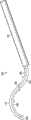
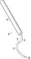
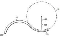
图1显示根据本发明的多种固定形状套管100的视图。图1A显示一固定形状套管100的侧视图,包含远侧部分110、近侧部分120、拐点130、 及手柄140。也显示末端200、该远侧部分110的弧长185、及该近侧部分120的弧长195。图1B显示1A图的固定形状套管100的透视图。图1C显示该远侧部分110的远区112、该远侧部分的中区113、窗口510、种籽形状的RBS 400、及具有远端320的导引线350,其中该导引线350被罩在固定形状套管100的手柄140内部。图1D显示延伸通过固定形状套管100的近侧部分120及远侧部分110的导引线350。图1E显示由远侧部分110的曲率、圆圈181的半径182、及远侧部分110的曲率半径180所限定的圆圈181。1F图显示由近侧部分120的曲率、圆圈191的半径192、及近侧部分120的曲率半径190所限定的圆圈191。 Figure 1 shows views of various fixed
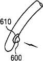
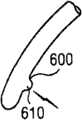
图2显示根据本发明的远侧部分110的多个末端200的侧视图。多个末端200可包含孔口500或窗口510和/或光源610和/或锯齿状末端600。图2J显示记忆线300,其中该记忆线300当由末端200伸出时形成平坦螺旋310。图2K显示远侧腔室210,其中记忆线300伸入该远侧腔室210内部时形成平坦螺旋310。 Figure 2 shows a side view of the plurality of
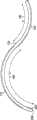
图3显示根据本发明的远侧部分110及近侧部分120的侧视图。 Figure 3 shows a side view of the
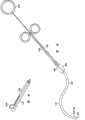
图4显示根据本发明的手柄140的透视图。图4A显示包含姆指环810的手柄140,其中该手柄包含非线柱塞800。图4B显示手柄140包含刻度盘820。图4C显示手柄140包含滑块830。4D图显示固定形状套管的实例,包含在该近侧部分120与该手柄140间的辐射屏蔽清管器900。种籽形状RBS 400被附接至导引线350,且该种籽形状RBS 400被罩在该清管器900内部。 Figure 4 shows a perspective view of a
图5显示根据本发明的已组装的固定形状套管100的插入。固定形状套管100包含定位器160。手柄140及近侧部分120偏离医生与病人的视轴220。眼球鞘为由前方边缘至后方视神经延伸的一层组织。眼球鞘的前方围绕着始于边缘的眼球结膜,而后方反折进入结膜穹窿的睑板结膜。 Figure 5 shows the insertion of an assembled
图6显示根据本发明的拆卸后的固定形状套管100的插入,其中该手柄140和/或辐射屏蔽清管器900在固定形状套管100定位之后通过连接器150而附接至近侧部分120。 6 shows insertion of a disassembled fixed
图7显示插入固定形状套管中的放射性核素短程治疗源(“RBS”)(例如种籽形状RBS 400)的实例。 Figure 7 shows an example of a radionuclide brachytherapy source ("RBS") inserted into a fixed shape cannula, such as the seed shaped
图8显示多种装置的侧向辐射剂量分布,包括本装置(沙陆塔(SalutarisMD))的剂量分布。图解表示距标靶中心(x轴)测得的相对辐射剂 量(y轴)的实例。沙陆塔装置呈现随着距标靶周边(距标靶中心约1毫米内的区域)距离的增加,辐射剂量愈来愈快速地降低。 Figure 8 shows the lateral radiation dose distribution for various devices, including the dose distribution for this device (Salutaris MD). The graph represents an example of the relative radiation dose (y-axis) measured from the center of the target (x-axis). The Shaluta device showed that the radiation dose decreased more and more rapidly as the distance from the periphery of the target (the area within about 1 mm from the center of the target) increased. the
图9显示本发明的固定形状套管100插入(根据后方辐射方法)与用于玻璃体内辐射方法910的装置插入的比较。 FIG. 9 shows a comparison of the insertion of a fixed
图10为“侧向”一词的限定说明。附图可为眼球的水平剖面的代表图,其中标靶为脉络膜新生血管膜(CNVM),来源为放射性源(例如种籽形状RBS 400)及巩膜位于放射性源与标靶间。 Figure 10 is a definition of the word "lateral". The attached figure is a representation of a horizontal section of the eyeball, where the target is the choroidal neovascular membrane (CNVM), the source is a radioactive source (eg, seed-shaped RBS 400) and the sclera is located between the radioactive source and the target. the
图11显示在1.5毫米深度在侧向测量的1毫米Sr-90源的辐射剂量分布的实例。 Figure 11 shows an example of the radiation dose distribution of a 1 mm Sr-90 source measured laterally at a depth of 1.5 mm. the
图12显示顺着线LR由RBS/标靶上向下观看时垂直于线LR的线的实例。 Figure 12 shows an example of a line perpendicular to lineLR as viewed from above the RBS/target along lineLR .
图13显示顺着线LR由RBS/标靶上向下观看时,垂直于线LR的等剂量(直接环绕标靶中央的区域,其中辐射剂量实质上均匀)的一个实例。在本实例中,辐射剂量实质均匀的区域距标靶中心延伸达约1.0毫米距离。 Figure 13 shows an example of the isodose (the area directly surrounding the center of the target where the radiation dose is substantially uniform) perpendicular to the lineLR looking down from the RBS/target along the lineLR . In this example, the region of substantially uniform radiation dose extends up to a distance of about 1.0 mm from the center of the target.
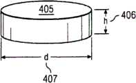
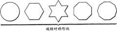
图14A为固定形状套管100的远侧部分110之前剖面视图,其中该固定形状套管100的顶部(例如远侧部分110)为圆化,而底部为平坦。图14B为图14A的远侧部分110的底视图。图14C为具有高度“h”406及直径“d”407的呈盘状405的RBS的实例的透视图。图14D显示具有多种形状(例如矩形、三角形、梯形)的多种RBS的侧剖面视图。图14E显示包含盘状基材361的RBS实例。在该基材361的底面363上为同位素362。图14F显示旋转性对称形状的实例。本发明非仅限于图14F所示形状。图14G显示包含窗口364(例如旋转性对称形状窗口)的辐射整形器366的一个实例。窗口364大致上为辐射可透性,而辐射整形器366大致上为辐射不透性。来自于RBS的辐射实质上被辐射整形器366所阻断或衰减而不会被窗口364所阻断或衰减。 14A is a front cross-sectional view of the
图15显示具有x轴维度、y轴维度、及z轴维度的椭圆体450的实例。 FIG. 15 shows an example of an ellipsoid 450 having an x-axis dimension, a y-axis dimension, and a z-axis dimension. the
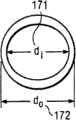
图16A显示固定形状套管100的近侧部分120的侧视图。图16B-D显示固定形状套管100的近侧部分120的剖面的内直径171、外直径172、及内半径173的实例。 FIG. 16A shows a side view of the
图17显示在拐点130及近侧部分120的眼球切线L3420间的角度θ1 425的实例。 FIG. 17 shows an example of the angle θ1 425 between the
图18A显示两个不同平面P1431及P2432。图18B显示由平面n1的法线 所限定的平面P1 431及由平面n2的法线所限定的平面P2432。图18C显示P1431与P2 432间的角度实例。 FIG. 18A shows two
图19A显示固定形状套管100的透视图,其中远侧部分110及近侧部分120的剖面为大致圆形。图19B显示固定形状套管100的透视图,其中远侧部分110及近侧部分120的剖面为平坦化成为丝带化构形。 Figure 19A shows a perspective view of fixed
图20A显示插入于一种用于将RBS朝向固定形状套管100的末端200前进的装置内部的盘状RBS的透视图。图20B为插入于一种用于将RBS朝向固定形状套管100的末端200前进的装置内部的多个圆柱形RBS的透视图。 FIG. 20A shows a perspective view of a disc-shaped RBS inserted inside a device for advancing the RBS towards the
图21显示具有辐射不透性壁的孔的透视图以及放射性核素短程治疗源固定于该孔内。 Figure 21 shows a perspective view of a hole with radiopaque walls and a radionuclide brachytherapy source immobilized within the hole. the
图22显示辐射分布数据,此处在边缘的辐射强度显著降低,即在标靶边缘快速降低。当采用屏蔽时,在边缘的辐射降低比未采用屏蔽时更快速。 Figure 22 shows the radiation distribution data, where the radiation intensity is significantly reduced at the edges, ie drops rapidly at the edges of the target. When shielding is used, the radiation decreases more rapidly at the edge than when it is not shielded. the
优选实施方案的详细说明 Detailed Description of Preferred Embodiments
本发明用于最小侵入性递送辐射至眼睛后部的方法及装置。不欲将本发明局限于任何理论或机理,相信本发明的递送辐射至眼睛后部的眼球下方法由于若干理由而具有优势。举例来说,眼球下手术为最小侵入性的,无需全面性的手术切开。这种独特的手术与需要切开的背景技术方法相比更快速、更容易、且造成更少副作用和/或更少并发症。此外,眼球下方法允许更简单的诊疗室内手术且恢复时间更快。 The present invention provides methods and devices for minimally invasive delivery of radiation to the back of the eye. Without wishing to limit the present invention to any theory or mechanism, it is believed that the present subocular method of delivering radiation to the back of the eye is advantageous for several reasons. For example, surgery under the eyeball is minimally invasive and does not require a full surgical incision. This unique procedure is quicker, easier, and causes fewer side effects and/or fewer complications than background art methods that require incision. Additionally, the subocular approach allows for simpler in-office procedures with faster recovery times. the
眼球下方法也允许眼球鞘及其它结构(例如巩膜)来协助于使用装置时导引装置与将装置固定定位。将眼球鞘保持于固定位置且在治疗期间固定在距标靶的一段距离,减少错误机会且增加剂量递送的可预测性。在玻璃体内方法(例如将辐射由玻璃体室内前方向后朝向标靶导引至眼睛视网膜而照射标靶区域)中,要求医生将装置固定于空旷的玻璃体室内距离标靶的固定位置与固定距离(参考图9)。医生难以准确固定定位经历任何时间长度。此外,医生/手术医生通常未知探头与视网膜间的正确距离;医生只能估算该距离。 The subocular approach also allows the sheath of the eye and other structures such as the sclera to assist in guiding and holding the device in place during use. Keeping the eye sheath in a fixed position and at a fixed distance from the target during treatment reduces the chance of error and increases the predictability of dose delivery. In intravitreal methods (such as directing radiation from the front of the vitreous chamber toward the target backwards to irradiate the target area of the eye), the physician is required to fix the device in the empty vitreous chamber at a fixed position and a fixed distance from the target ( Refer to Figure 9). Physicians have difficulty immobilizing the position accurately for any length of time. Also, the doctor/surgeon usually does not know the correct distance between the probe and the retina; the doctor can only estimate it. the
本发明方法由眼睛后侧向前导引辐射至标靶,辐射被屏蔽于眼睛后部。不欲将本发明局限于任何理论或机理,相信这样的方法让病人免于眼睛后方比眼睛更深入的组织接收到游离辐射。视网膜前方法(例如经由 将辐射由视网膜前侧向后导引朝向标靶来照射标靶区)照射眼睛前方结构(例如角膜、虹膜、睫状体、晶状体),可能照射比病灶更深入的组织,例如眼眶周围脂肪、骨骼、及脑部。玻璃体内辐射方法也可能照射比病灶更深部的组织(例如眼眶周围脂肪、骨骼、脑部)同时在正向也可能照射晶状体、睫状体及角膜。 The method of the present invention directs the radiation to the target from the back side of the eye forward, and the radiation is shielded at the back of the eye. Without intending to limit the present invention to any theory or mechanism, it is believed that such a method protects the patient from ionizing radiation received by tissues deeper than the eye behind the eye. Preretinal approaches (eg, irradiating a target area by directing radiation from the anterior side of the retina back toward the target) irradiate structures in the front of the eye (eg, cornea, iris, ciliary body, lens), possibly irradiating tissues deeper than the lesion , such as periorbital fat, bone, and brain. Intravitreal radiation approaches may also target tissues deeper than the lesion (eg, periorbital fat, bone, brain) and may also target the lens, ciliary body, and cornea in the forward direction. the
在本发明之前施用至眼睛的放射性治疗通常涉及侵入性眼睛手术。例如辐射治疗业界称作为“COMS研究”的权威报告揭示一种方案采用侵入性手术程序来切割眼周组织安放入短程放射治疗装置。此方面不像本发明的最少侵入性眼球下方法。 Radiation therapy administered to the eye prior to the present invention typically involved invasive eye surgery. For example, an authoritative report known in the radiation therapy industry as the "COMS Study" reveals an approach using an invasive surgical procedure to cut tissue around the eye for placement in a brachytherapy device. This aspect is not like the least invasive subocular approach of the present invention. the
背景技术曾经揭示多种使用短程放射治疗装置来由眼球后方照射病灶的多种短程治疗装置及方法。但这样的技术并未采用本发明的最小侵入性眼球下方法。当研读背景技术的揭示时,技艺界人士容易了解背景技术揭示的手术为象限切开法或眼球后眼眶内方法,任一种方法都不是最小侵入性眼球下方法。 BACKGROUND OF THE INVENTION Various brachytherapy devices and methods using brachytherapy devices to irradiate lesions from the back of the eye have been disclosed. Such techniques, however, do not employ the minimally invasive subocular approach of the present invention. When perusing the background art disclosure, one skilled in the art readily understands that the surgery disclosed in the background art is a quadrantotomy or a retro-orbital intra-orbital approach, neither of which is a minimally invasive sub-ocular approach. the
以下为此处所述与特定组件相对应的组件符号窗体: The following are the component symbol forms that correspond to specific components as described here:
100...固定形状套管 100...fixed shape sleeve
110...远侧部分 110...distal part
112...远侧部分的远区 112...far zone of the distal portion
113...远侧部分的中区 113...central region of the distal portion
120...近侧部分 120...proximal part
130...拐点 130...inflection point
140...手柄 140...handle
150...连接器 150...connector
160...定位器 160...Positioner
171...套管的内直径 171...inner diameter of casing
172...套管的外直径 172... Outer diameter of casing
173...近侧部分的内半径 173...inner radius of proximal part
180...远侧部分的曲率半径 180...radius of curvature of the distal portion
181...由远侧部分的弯曲所限定的圆形/卵圆形 181...circle/oval defined by curvature of distal portion
182...由远侧部分的弯曲所限定的圆形/卵圆形的半径 182...the radius of the circle/oval defined by the curvature of the distal portion
185...远侧部分的弧长 185...Arc length of the distal portion
190...近侧部分的曲率半径 190...radius of curvature of proximal portion
191...由近侧部分的弯曲所限定的圆形/卵圆形 191...circle/oval defined by curvature of proximal portion
192...由近侧部分的弯曲所限定的圆形/卵圆形的半径 192...the radius of the circle/oval defined by the curvature of the proximal portion
195...近侧部分的弧长 195...The arc length of the proximal part
200...末端 200...end
210...远侧腔室(盘状) 210...distal chamber (disc)
220...使用者的视轴 220...View axis of user
230...眼球鞘 230...Eye sheath
235...巩膜 235...sclera
300...记忆线 300...memory line
310...平坦螺旋 310...flat spiral
320...线的远端 320... the far end of the line
350...导引线 350...guide wire
361...基材 361...substrate
362...同位素(或“放射性核素”) 362...isotopes (or "radionuclides")
363...基材底面 363... Substrate bottom surface
364...辐射整形器的窗口 364... Window of the Radiation Shaper
366...辐射整形器 366... Radiation Shaper
400...种籽形RBS,种籽形放射性核素短程治疗源 400...seed-shaped RBS, seed-shaped radionuclide brachytherapy source
405...圆盘 405...disc
406...圆盘高度 406...disc height
407...圆盘直径 407...disc diameter
410...线的放射性源部 410...line radioactive source
420...线l3420...Line l3
425...角θ1425...angle θ1
431...平面P1431...Plane P1
432...平面P2432...Plane P2
450...椭圆体 450...ellipsoid
500...孔口 500...orifice
510...窗口 510...window
520...孔口/窗口的远缘 520...far edge of orifice/window
600...锯齿状末端 600...serrated ends
610...光源 610...Light source
800...非线柱塞 800...non-linear plunger
810...拇指环 810...thumb ring
820...刻度盘 820... dial
830...滑块 830...slider
900...辐射屏蔽清管器 900... Radiation shielding pig
910...玻璃体内辐射方法所使用的装置 910...Apparatus for intravitreal radiation methods
如此处使用,“约”一词表示该数目加或减10%。例如约50度角的实施方案包括45度至55度间的角度。 As used herein, the word "about" means plus or minus 10% of that number. For example, embodiments with an angle of about 50 degrees include angles between 45 degrees and 55 degrees. the
眼睛 Eye
哺乳动物眼睛大致为球状结构,经由将外部照明对象的影像形成于感光组织视网膜上而发挥视觉功能。眼睛的功能组件的基本支持结构为大致球状的强韧白色外壳即巩膜235,巩膜主要由胶原结缔组织所组成,借助眼球内部压力来维持球形。巩膜235外部围绕眼球鞘230(眼球筋膜),眼球鞘是由前方边缘延伸至后方视神经的组织薄层。眼球鞘230的前方包围着眼球结膜,眼球结膜为源自于边缘的薄形、松散、血管床化淋巴组织,而后方在结膜穹窿反折入睑板结膜。巩膜235的前方接合角膜,角膜为透明且较为凸起结构。巩膜与角膜接合该点称作为边缘。巩膜235的前部支持且容纳发挥将入射光线聚焦功能的组件,例如角膜及晶状体,以及发挥调节进入眼睛的光线强度的功能的组件例如虹膜。眼球后部支持视网膜及相关组织。 Mammalian eyes are roughly spherical structures that perform visual functions by forming images of externally illuminated objects on the photosensitive retina. The basic support structure of the functional components of the eye is a roughly spherical tough white shell, namely the
在眼球后部(在此处称作为“眼睛后部”)紧邻巩膜235内表面有脉络膜,脉络膜为灵活供应血管的含色素组织薄层。脉络膜相邻其内表面部分包含微血管网络,称作为脉络膜微血管,脉络膜微血管的重要性在于将氧气及养份供应到视网膜邻近各层。紧邻于脉络膜前方为视网膜,视网膜为眼后段的最内层,接收由眼球前部的屈光组件所形成的影像。视网膜的感光杆状细胞及锥状细胞被落入细胞上的光线刺激,将其感觉通过视网膜神经节细胞送至大脑。视网膜的中区称作为“黄斑部”,黄斑部大致上是由中心视网膜动脉的上及下颞骨分支所画界,大部分负责色彩视力、对比灵敏度及形状辨识。黄斑部的极为中部称作为“中央窝”,中央窝负责视锐度。 At the back of the eyeball (herein referred to as "the back of the eye"), adjacent to the inner surface of the
将放射性核素短程治疗源(“RBS”)导入眼球后部的新的眼球下方法 Novel Subocular Method for Introducing a Radionuclide Brachytherapy Source (“RBS”) into the Back of the Eye
本发明的特征在于一种以最小侵入性方式(就眼内空间而言)由外侧 将辐射导入到眼睛后部的方法。大致上,该方法包含由巩膜235外表面照射标靶。标靶可为黄斑部、视网膜、巩膜235、和/或脉络膜。在一些实施方案中,标靶可在眼睛的玻璃体侧上。在一些实施方案中,标靶为血管新生病灶。在一些实施方案中,标靶接收大于约10格雷/分钟的辐射剂量率。 The invention features a method of introducing radiation into the back of the eye from the outside in a minimally invasive manner (with respect to the intraocular space). In general, the method involves illuminating the target from the outer surface of the
在一些实施方案中,该方法包含使用中空套管100来递送RBS至与标靶相对应的巩膜235该区。(虽然本发明的套管100用于眼球下方法,但其它仪器诸如内视镜也可根据本新的眼球下方法使用)。套管100可在眼睛的外部曲线上滑动来到达眼睛后部。特别地,在一些实施方案中,该方法包含将包含RBS的套管导入至位于眼球鞘230与巩膜235间的眼睛后部,让眼睛后部暴露于辐射。套管100可在眼睛边缘后方的点插入(例如在边缘与结膜穹窿间的任一点)。 In some embodiments, the method comprises using the
该方法进一步包含通过用于使RBS前进的装置将RBS通过套管100前进至该远侧部分110的末端200。 The method further comprises advancing the RBS through the
在一些实施方案中,该方法进一步包含将眼睛标靶(例如黄斑部)暴露于辐射的步骤。在一些实施方案中,该方法包含以于黄斑部的血管新生生长为标靶。 In some embodiments, the method further comprises the step of exposing an ocular target (eg, the macula) to radiation. In some embodiments, the method comprises targeting neovascular growth at the macula. the
在一些实施方案中,RBS置于眼球下方空间紧邻于巩膜235之上覆盖有受到眼球病症(例如WAMD、肿瘤)影响的脉络膜和/或视网膜部分的该巩膜部分。如此处使用,放置于“紧邻附近”的RBS表示该RBS距巩膜235表面约0毫米至约10毫米。在一些实施方案中,辐射经由巩膜235照射至脉络膜和/或视网膜。 In some embodiments, the RBS is placed in the subocular space immediately above the portion of the
在一些实施方案中,将套管100插入眼球鞘230与巩膜235间的步骤进一步包含将套管100插入眼睛的上颞骨象限。在一些实施方案中,将套管100插入眼球鞘230与巩膜235间的步骤进一步包含将套管100插入眼睛的下颞骨象限。在一些实施方案中,将套管100插入眼球鞘230与巩膜235间的步骤进一步包含将套管100插入眼睛的上鼻骨象限。在一些实施方案中,将套管100插入眼球鞘230与巩膜235间的步骤进一步包含将套管100插入眼睛的下鼻骨象限。 In some embodiments, the step of inserting the
位于套管100远端的RBS照射标靶,标靶接收大于约10格雷/分钟的剂量率。在一些实施方案中,RBS向标靶提供大于约11格雷/分钟的剂量率。在一些实施方案中,RBS向标靶提供大于约12格雷/分钟的剂量率。在一 些实施方案中,RBS提供向标靶大于约13格雷/分钟的剂量率。在一些实施方案中,RBS向标靶提供大于约14格雷/分钟的剂量率。在一些实施方案中,RBS向标靶提供大于约15格雷/分钟的剂量率。在一些实施方案中,RBS提供约10至15格雷/分钟的剂量率。在一些实施方案中,RBS提供约15至20格雷/分钟的剂量率。在一些实施方案中,RBS提供约20至30格雷/分钟的剂量率。在一些实施方案中,RBS提供约30至40格雷/分钟的剂量率。在一些实施方案中,RBS提供约40至50格雷/分钟的剂量率。在一些实施方案中,RBS提供约50至60格雷/分钟的剂量率。在一些实施方案中,RBS提供约60至70格雷/分钟的剂量率。在一些实施方案中,RBS提供约70至80格雷/分钟的剂量率。在一些实施方案中,RBS提供约80至90格雷/分钟的剂量率。在一些实施方案中,RBS提供约90至100格雷/分钟的剂量率。在一些实施方案中,RBS提供大于100格雷/分钟的剂量率。 The RBS located at the distal end of the
在一些实施方案中,由RBS至标靶的距离为约0.4毫米至2.0毫米。在一些实施方案中,由RBS至标靶的距离为约0.4毫米至1.0毫米。在一些实施方案中,由RBS至标靶的距离为约1.0毫米至1.6毫米。在一些实施方案中,由RBS至标靶的距离为约1.6毫米至2.0毫米。 In some embodiments, the distance from the RBS to the target is about 0.4 mm to 2.0 mm. In some embodiments, the distance from the RBS to the target is about 0.4 mm to 1.0 mm. In some embodiments, the distance from the RBS to the target is about 1.0 mm to 1.6 mm. In some embodiments, the distance from the RBS to the target is about 1.6 mm to 2.0 mm. the
在一些实施方案中,RBS向标靶提供约15至20格雷/分钟的剂量率。在一些实施方案中,RBS向标靶提供约20至25格雷/分钟的剂量率。在一些实施方案中,RBS向标靶提供约25至30格雷/分钟的剂量率。在一些实施方案中,RBS向标靶提供约30至35格雷/分钟的剂量率。在一些实施方案中,RBS向标靶提供约35至40格雷/分钟的剂量率。在一些实施方案中,RBS向标靶提供约40至50格雷/分钟的剂量率。在一些实施方案中,RBS向标靶提供约50至60格雷/分钟的剂量率。在一些实施方案中,RBS向标靶提供约60至70格雷/分钟的剂量率。在一些实施方案中,RBS向标靶提供约70至80格雷/分钟的剂量率。在一些实施方案中,RBS向标靶提供约80至90格雷/分钟的剂量率。在一些实施方案中,RBS向标靶提供约90至100格雷/分钟的剂量率。在一些实施方案中,RBS向标靶提供大于约100格雷/分钟的剂量率。 In some embodiments, the RBS provides a dose rate of about 15 to 20 Gy/min to the target. In some embodiments, the RBS provides a dose rate of about 20 to 25 Gy/min to the target. In some embodiments, the RBS provides a dose rate of about 25 to 30 Gy/min to the target. In some embodiments, the RBS provides a dose rate of about 30 to 35 Gy/min to the target. In some embodiments, the RBS provides a dose rate of about 35 to 40 Gy/min to the target. In some embodiments, the RBS provides a dose rate of about 40 to 50 Gy/min to the target. In some embodiments, the RBS provides a dose rate of about 50 to 60 Gy/min to the target. In some embodiments, the RBS provides a dose rate of about 60 to 70 Gy/min to the target. In some embodiments, the RBS provides a dose rate of about 70 to 80 Gy/min to the target. In some embodiments, the RBS provides a dose rate of about 80 to 90 Gy/min to the target. In some embodiments, the RBS provides a dose rate of about 90 to 100 Gy/min to the target. In some embodiments, the RBS provides a dose rate to the target greater than about 100 Gy/min. the
本方法可有效用于治疗和/或处置病情(例如眼睛病症)。举例来说,本方法可用于治疗和/或处理湿型(血管新生)老化相关黄斑部退化。本方法并非局限于治疗和/或处置湿型(血管新生)老化相关黄斑部退化。例如本方法可用于治疗和/或处置包括黄斑部退化、异常细胞增殖、脉络膜血 管新生、视网膜病变(例如糖尿病性视网膜病变、玻璃体视网膜病变)、黄斑部水肿、及肿瘤(例如眼球内黑素瘤、视网膜母细胞瘤)等病症。 The methods are useful in the treatment and/or management of medical conditions (eg, eye disorders). For example, the method can be used to treat and/or manage wet (angiogenesis) age-related macular degeneration. The present method is not limited to the treatment and/or management of wet (angiogenesis) age-related macular degeneration. For example, the method can be used for the treatment and/or management of diseases including macular degeneration, abnormal cell proliferation, choroidal neovascularization, retinopathy (e.g. diabetic retinopathy, vitreoretinopathy), macular edema, and tumors (e.g. intraocular melanoma). tumor, retinoblastoma) and other diseases. the
眼球下手术的优点 Advantages of eye surgery
不欲将本发明局限于任何理论或机理,相信本发明的新的眼球下方法优于背景技术,原因在于眼球下方法较为不具侵入性(例如未侵入眼球下空间),只需局部麻醉且病人复原时间更快速。举例来说,通过将放射性斑块缝合在眼睛后部的巩膜235上而将辐射导入眼睛后部的技术要求360度环切术(例如结膜的切开),分离四条直肌以及全面性眼球手术。此外,当放射性斑块留置定位然后于数日后移出时需要第二次手术。本发明方法更容易执行。此外,将眼后极暴露于辐射的眼球内手术涉及执行玻璃体切开术,以及将放射性探头放置且固定于视网膜前方玻璃体腔经历一段长时间而无稳定化机制。此种技术难以执行,需要侵入眼球内空间,容易发生多种可能的并发症诸如视网膜剥离、白内障、青光眼、和/或眼内炎风险。由于此种技术复杂,因此需要其它玻璃体视网膜手术医生的共同参与。本发明方法更容易执行,最小侵入性,不会造成眼球内构造损伤的风险。此外,本发明方法无需接受额外玻璃体视网膜手术医生的训练,原因在于这样的方法可由任何眼科手术医师执行。 Without wishing to limit the invention to any theory or mechanism, it is believed that the novel subocular method of the present invention is superior to the background art in that the subocular method is less invasive (eg, does not invade the subocular space), requires only local anesthesia and the patient Recovery time is faster. For example, the technique of introducing radiation into the back of the eye by suturing a radioactive plaque to the
如此处使用,“最小侵入性方法”表示不要求仪器导入眼睛的眼球内空间(前室、后室、或玻璃体舱)用以将放射性源递送至眼睛后部;或一种不要求将放射性斑块缝合于巩膜上或全面性结膜环切术的方法。例如,本发明的最小侵入性方法只要求结膜及眼球鞘230的小型切口用来插入包含RBS的套管100至眼睛后部。优选的方法是通过颞骨上象限,但也可采用通过鼻骨上象限、颞骨下象限或鼻骨下象限的进入方式。 As used herein, "minimally invasive approach" means a method that does not require instrumentation into the intraocular space (anterior, posterior, or vitreous compartment) of the eye to deliver a radioactive source to the back of the eye; or a method that does not require the introduction of a radioactive spot Methods of block suture on the sclera or general conjunctival circumcision. For example, the minimally invasive method of the present invention requires only a small incision in the conjunctiva and
本发明的特征在于一种将辐射导入人眼的方法,包含下列步骤:将一套管100插入人眼的眼球鞘230与巩膜235之间,位于人眼边缘后方的点;其中套管100包含具有约9毫米至15毫米的曲率半径180及约25毫米至35毫米的弧长185的远侧部分110;近侧部分120;以及用于将RBS朝向套管100的末端200(例如远侧部分110的末端200)前进的装置;将远侧部分110安置于血管新生病灶后方的巩膜235上或附近;将该RBS前进至远侧部分110的末端200;以及将血管新生病灶暴露于该RBS。 The invention features a method of introducing radiation into a human eye comprising the steps of: inserting a
在一些实施方案中,暴露于辐射的巩膜235的区域直径为约0.1毫米至约0.5毫米。在一些实施方案中,暴露于辐射的巩膜235的区域直径为约0.5 毫米至约2毫米。在一些实施方案中,暴露于辐射的巩膜235的区域直径为约2毫米至约3毫米。在一些实施方案中,暴露于辐射的巩膜235的区域直径为约3毫米至约5毫米。在一些实施方案中,暴露于辐射的巩膜235的区域直径为约5毫米至约10毫米。在一些实施方案中,暴露于辐射的巩膜235的区域直径为约10毫米至约25毫米。 In some embodiments, the region of the
套管 Casing
本发明的特征在于一种用于将RBS递送至眼睛后部的固定形状套管100。该固定形状套管100具有经限定的固定形状,包含通过拐点130而连接至近侧部分120的远侧部分110。固定形状套管100的远侧部分110用于环绕眼球部分定位。在一些实施方案中,将固定形状套管100的远侧部分110插入眼球鞘230下方而位于巩膜235之上。在一些实施方案中,固定形状套管100为中空。 The present invention features a fixed
如此处使用,具有“固定的”形状的固定形状套管100是指具有单一持久形状而无法被操作成另一种形状的固定形状套管100。举例来说,本发明的固定形状套管100具有“固定的”形状,原因在于其通常具有一种形状,而内视镜不具有“固定的”形状,原因在于内视镜为可挠性而可操作成为另一种形状。具有“固定的”形状的固定形状套管100也可由具有若干可挠性的材料所制成。如此当施加压力于本发明的固定形状套管100时可弯曲。但当压力移开时,本发明的固定形状套管100可回复其原先的固定形状或保有部分变形形状。 As used herein, a fixed-
在一些实施方案中,拐点130可定义为在曲线上其中弯曲标记或弯曲方向改变的点。在一些实施方案中,该固定形状套管在远侧部分及近侧部分间可有直线部分。如此,在一些实施方案中,近侧部分与远侧部分在弯曲改变标记的拐点分开。在一些实施方案中,近侧部分结束在弯曲由有限值改变成零的一点。 In some embodiments, an
在一些实施方案中,拐点130协助将固定形状套管100的近侧部分120弯离个体(例如病人)的视轴220及弯离将固定形状套管100插入个体的使用者(例如医生)的视轴220。在一些实施方案中,经由采用同轴检眼镜装置诸如间接检眼镜或手术显微镜,同时将固定形状套管100固定定位,使用者可目测观察个体的眼睛后部。 In some embodiments,
固定形状套管的远侧部分维度 Dimensions of the distal portion of the fixed-shape cannula
成人的眼球维度相当恒定,多项调查研究中通常改变不超过约1毫 米。但对于远视眼及近视眼,眼球的前后直径可能显著偏离正常测量值。 Eye dimensions in adults are fairly constant, typically varying by no more than about 1 mm across several studies. But for hyperopia and nearsightedness, the anteroposterior diameter of the eyeball may deviate significantly from normal measurements. the
正视眼眼球的外部前后直径为约21.7毫米至28.75毫米的范围,平均约为24.15毫米(半径为约10.8毫米至14.4毫米的范围,平均约为12.1毫米);而内部前后直径平均约为22.12毫米(半径平均约为11.1毫米)。对于高度远视眼及近视眼,前后直径经常分别低抵约20毫米及高达约29毫米或以上。 The external anterior-posterior diameter of the emmetropic eyeball ranges from approximately 21.7 mm to 28.75 mm, with an average of approximately 24.15 mm (the radius ranges from approximately 10.8 mm to 14.4 mm, with an average of approximately 12.1 mm); while the internal anterior-posterior diameter averages approximately 22.12 mm (The average radius is about 11.1mm). For high hypermetropia and nearsightedness, the anterior and posterior diameters are often as low as about 20 millimeters and as high as about 29 millimeters or more, respectively. the
横向直径(例如对于由鼻骨侧至颞骨侧测量得的解剖赤道线的眼球直径)平均约为23.48毫米(半径平均约为11.75毫米),纵向直径(例如对于解剖赤道线由上至下测量得的眼球直径)平均约为23.48毫米(半径平均约为11.75毫米)。在解剖赤道线的眼球周长平均约为74.91毫米。眼球容积约为6.5毫升至7.2毫升且具有约22.86平方厘米的表面积。 Transverse diameter (e.g., eyeball diameter for the anatomical equator line measured from the nasal bone side to the temporal bone side) averaged about 23.48 mm (radius averaged about 11.75 mm), and longitudinal diameter (e.g., the anatomical equator line measured from top to bottom Eyeball diameter) averaged about 23.48 mm (radius averaged about 11.75 mm). The average eye circumference at the anatomical equator is about 74.91 mm. The eyeball has a volume of approximately 6.5 milliliters to 7.2 milliliters and has a surface area of approximately 22.86 square centimeters. the
固定形状套管100的远侧部分110可以多种方式设计。在一些实施方案中,固定形状套管100的远侧部分110具有约25毫米至35毫米的弧长185。 The
在一些实施方案中,远侧部分110的弧长185(例如远侧部分110的弧111的长度)可具有不等长度。例如远视病人或儿童病人的眼睛较小,可能要求远侧部分110的较小弧长185。或者例如,固定形状套管100的不同插入点(例如边缘、结膜穹窿)可能要求远侧部分110的不同弧长185。在一些实施方案中,远侧部分110的弧长185可为约10毫米至约15毫米。在一些实施方案中,远侧部分110的弧长185可为约15毫米至约20毫米。在一些实施方案中,远侧部分110的弧长185可为约20毫米至约25毫米。在一些实施方案中,远侧部分110的弧长185可为约25毫米至约30毫米。在一些实施方案中,远侧部分110的弧长185可为约30毫米至约35毫米。在一些实施方案中,远侧部分110的弧长185可为约35毫米至约50毫米。在一些实施方案中,远侧部分110的弧长185可为约50毫米至约75毫米。 In some embodiments, the
如此处使用,固定形状套管的远侧部分110的“弧长”185一词是指由远侧部分110的末端200测量至拐点130的弧长。固定形状套管100的远侧部分110的“曲率半径”180一词是指由远侧部分110的弯曲所限定的圆形/卵圆形181的半径182的长度(参考图19A)。在一些实施方案中,本发明采用一种独特的眼球下插入方法,其中弧长被设计为具有可横亘眼球鞘及位于眼球鞘入口点与标靶区(例如黄斑部)间的眼球部分的足够长度。 As used herein, the term "arc length" 185 of the
在一些实施方案中,固定形状套管100的远侧部分110具有约9毫米至15毫米的曲率半径180。在一些实施方案中,固定形状套管100的远侧部 分110具有约9毫米至10毫米的曲率半径180。在一些实施方案中,固定形状套管100的远侧部分110具有约10毫米至11毫米的曲率半径180。在一些实施方案中,固定形状套管100的远侧部分110具有约11毫米至12毫米的曲率半径180。在一些实施方案中,固定形状套管100的远侧部分110具有约12毫米至13毫米的曲率半径180。在一些实施方案中,固定形状套管100的远侧部分110具有约13毫米至14毫米的曲率半径180。在一些实施方案中,固定形状套管100的远侧部分110具有约14毫米至15毫米的曲率半径180。在一些实施方案中,远侧部分110至拐点130的弧长185也用来限制该固定形状套管100顺着巩膜235插入的深度,防止远侧部分110的末端200意外损伤后睫状体动脉或视神经。 In some embodiments, the
在一些实施方案中,远侧部分110具有实质上等于成人眼睛的巩膜235的曲率半径的曲率半径180。不欲将本发明局限于任何理论或机理,相信远侧部分110的曲率半径180实质上等于成人眼睛的巩膜235的曲率半径的优异原因在于可确保暴露于辐射的区域为巩膜235的外表面,该区通常位于黄斑部之上。此外,该项设计允许正确安置RBS,且允许使用者(例如手术医生)在施用辐射剂量期间只要最小努力即可让该RBS保持固定于正确位置。如此允许改进的剂量递送的几何准确度及改进的剂量给予。 In some embodiments, the
在一些实施方案中,远侧部分110的曲率半径180为恒定。例如,远侧部分110的曲率半径180恒定于12毫米。在一些实施方案中,远侧部分110的曲率半径180为可变的。例如,远侧部分110的曲率半径180在远区112较大而在中区113较小。 In some embodiments, the radius of
不欲将本发明局限于任何理论或机理,相信不同的可变的曲率半径提供在特殊情况下更容易且更准确地定位,诸如对于近视眼,其中前后直径大于垂直直径。在此种情况下,可能优选使用具有总体而言较大的曲率半径180的远侧部分110的固定形状套管100,特别为具有远区112的曲率半径比中区113的曲率半径相对更短。同理,可能优选使用具有总体而言较小的曲率半径180的远侧部分110的固定形状套管100,特别为具有远区112的曲率半径比中区113的曲率半径相对较大。 Without intending to limit the invention to any theory or mechanism, it is believed that the different variable radii of curvature provide for easier and more accurate positioning in special cases, such as for myopia, where the anterior-posterior diameter is greater than the vertical diameter. In such cases, it may be preferable to use a fixed
固定形状套管100的远侧部分110及近侧部分120各自具有个别纵剖面的内直径171及外直径172。如图16所示,在一些实施方案中,远侧部分110的纵剖面的内直径171为恒定(例如固定形状套管100的内侧具有圆 形剖面)。在一些实施方案中,远侧部分110的纵剖面的内直径171为可变(例如固定形状套管100的内侧具有卵圆形剖面)。在一些实施方案中,远侧部分110的纵剖面的外直径172为恒定(例如固定形状套管100的外侧具有圆形剖面)。在一些实施方案中,远侧部分110的纵剖面的外直径172为可变(例如固定形状套管100的外侧具有卵圆形剖面)。 The
在一些实施方案中,固定形状套管100具有大致上为圆形的外剖面形状。在一些实施方案中,固定形状套管100具有大致上为弧形的外剖面形状。在一些实施方案中,固定形状套管100具有大致上为椭圆形、矩形、卵形、或梯形的外剖面形状。 In some embodiments, fixed
在一些实施方案中,固定形状套管100具有经组配而允许RBS通过其中的内剖面形状。 In some embodiments, fixed
在一些实施方案中,固定形状套管100具有大致上为圆形的内剖面形状。在一些实施方案中,固定形状套管100具有大致上为弧形的内剖面形状。在一些实施方案中,固定形状套管100具有大致上为椭圆形、矩形、卵形、或梯形的内剖面形状。 In some embodiments, fixed
在一些实施方案中,远侧部分110的纵剖面的平均外直径172为约0.1毫米至0.4毫米。在一些实施方案中,远侧部分110的纵剖面的平均外直径172为约0.4毫米至1.0毫米。在一些实施方案中,远侧部分110的纵剖面的平均外直径172为约0.9毫米。在一些实施方案中,远侧部分110的纵剖面的平均外直径172为约1.0毫米至2.0毫米。在一些实施方案中,远侧部分110的纵剖面的平均外直径172为约2.0毫米至5.0毫米。在一些实施方案中,远侧部分110的纵剖面的平均外直径172为约5.0毫米至10.0毫米。 In some embodiments, the average
在一些实施方案中,远侧部分110的纵剖面的平均内直径171为约0.1毫米至0.4毫米。在一些实施方案中,远侧部分110的纵剖面的平均内直径171为约0.4毫米至1.0毫米。在一些实施方案中,远侧部分110的纵剖面的平均内直径171为约0.9毫米。在一些实施方案中,远侧部分110的纵剖面的平均内直径171为约1.0毫米至2.0毫米。在一些实施方案中,远侧部分110的纵剖面的平均内直径171为约2.0毫米至5.0毫米。在一些实施方案中,远侧部分110的纵剖面的平均内直径171为约5.0毫米至10.0毫米。 In some embodiments, the average
在一些实施方案中,远侧部分110的纵剖面的平均外直径172为约0.4毫米及远侧部分110的纵剖面的平均内直径171为约0.1毫米(例如壁厚度约为0.15毫米)。在一些实施方案中,远侧部分110的纵剖面的平均外直径 172为约0.7毫米及远侧部分110的纵剖面的平均内直径171为约0.4毫米(例如壁厚度约为0.15毫米)。在一些实施方案中,远侧部分110的纵剖面的平均外直径172为约0.9毫米及远侧部分110的纵剖面的平均内直径171为约0.6毫米(例如壁厚度约为0.15毫米)。在一些实施方案中,远侧部分110的纵剖面的平均外直径172为约1.3毫米及远侧部分110的纵剖面的平均内直径171为约0.8毫米(例如壁厚度约为0.25毫米)。在一些实施方案中,远侧部分110的纵剖面的平均外直径172为约1.7毫米及远侧部分110的纵剖面的平均内直径171为约1.2毫米(例如壁厚度约为0.25毫米)。在一些实施方案中,远侧部分110的纵剖面的平均外直径172为约1.8毫米及远侧部分110的纵剖面的平均内直径171为约1.4毫米(例如壁厚度约为0.20毫米)。在一些实施方案中,远侧部分110的纵剖面的平均外直径172为约2.1毫米及远侧部分110的纵剖面的平均内直径171为约1.6毫米(例如壁厚度约为0.25毫米)。 In some embodiments, the average
在一些实施方案中,远侧部分110的直径为12号至22号线针尺寸。 In some embodiments, the diameter of the
在一些实施方案中,远侧部分壁厚度(例如在远侧部分110的内直径171至远侧部分110的外直径172间测量)为约0.01毫米至约0.1毫米。在一些实施方案中,远侧部分壁厚度(例如在远侧部分110的内直径171至远侧部分110的外直径172间测量)为约0.1毫米至约0.3毫米。在一些实施方案中,远侧部分壁厚度为约0.3毫米至约1.0毫米。在一些实施方案中,远侧部分壁厚度为约1.0毫米至约5.0毫米。在一些实施方案中,远侧部分壁厚度顺着远侧部分110的纵向为恒定。如图16B所示,在一些实施方案中,远侧部分壁厚度大约恒定于内直径171及外直径172。在一些实施方案中,远侧部分壁厚度在整个远侧部分110改变,例如顺着远侧部分110的纵向改变。如图16C及16D所示,在一些实施方案中,远侧部分壁厚度大约在内直径171至外直径172而改变。 In some embodiments, the distal portion wall thickness (eg, measured between the
固定形状套管的近侧部分维度 Proximal Section Dimensions of Fixed Shape Cannulas
固定形状套管100的近侧部分120也可以多种方式设计。在一些实施方案中,固定形状套管100的近侧部分120具有约10毫米至75毫米的弧长195。 The
近侧部分120的弧长195(例如近侧部分120的弧的长度)可具有不等长度。在一些实施方案中,近侧部分120的弧长195为约10毫米至约15毫米。在一些实施方案中,近侧部分120的弧长195为约15毫米至约18毫米。在 一些实施方案中,近侧部分120的弧长195为约18毫米至约25毫米。在一些实施方案中,近侧部分120的弧长195为约25毫米至约50毫米。在一些实施方案中,近侧部分120的弧长195为约50毫米至约75毫米。 The
如此处使用,固定形状套管100的近侧部分120的“弧长”195一词是指由拐点130测量至近侧部分120的相对端的弧长。固定形状套管100的近侧部分120的“曲率半径”190一词是指由近侧部分120的弯曲所限定的圆形/卵圆形191的半径192的长度(参考图19B)。 As used herein, the term "arc length" 195 of the
在一些实施方案中,固定形状套管100的近侧部分120具有约固定形状套管100的近侧部分120的内半径173间的曲率半径190例如为0.1毫米至1米。在一些实施方案中,近侧部分120的曲率半径190为常数。在一些实施方案中,近侧部分120的曲率半径190为变数。 In some embodiments, the
固定形状套管100的远侧部分110及近侧部分120各自具有个别纵剖面的内直径171及外直径172。如图16所示,在一些实施方案中,近侧部分120的纵剖面的内直径171为恒定(例如固定形状套管100的内侧具有圆形剖面)。在一些实施方案中,近侧部分120的纵剖面的内直径171为可变(例如固定形状套管100的内侧具有卵圆形剖面)。在一些实施方案中,近侧部分120的纵剖面的外直径172为恒定(例如固定形状套管100的外侧具有圆形剖面)。在一些实施方案中,近侧部分120的纵剖面的外直径172为可变(例如固定形状套管100的外侧具有卵圆形剖面)。 The
在一些实施方案中,固定形状套管100具有大致上为圆形的外剖面形状。在一些实施方案中,固定形状套管100具有大致上为椭圆形、矩形、卵形、或梯形的外剖面形状。 In some embodiments, fixed
在一些实施方案中,固定形状套管100具有经组配而允许RBS通过其中的内剖面形状。 In some embodiments, fixed
在一些实施方案中,固定形状套管100具有大致上为圆形的内剖面形状。在一些实施方案中,固定形状套管100具有大致上为椭圆形、矩形、卵形、或梯形的内剖面形状。 In some embodiments, fixed
如图17所示,线L3420表示在拐点130和/或边缘的眼球切线。线L3420与线L4(固定形状套管100的直线部分或固定形状套管100的直线部分的并行线)形成角θ1 425(参考图17)。固定形状套管100可以多种方式组成,因此角θ1 425可具有不等数值。在一些实施方案中,角θ1 425为大于约0度至180度。在一些实施方案中,若固定形状套管100弯曲角度较大,则角θ1 425 的数值较大。 As shown in FIG. 17,
在一些实施方案中,角θ1 425为约1度至10度。在一些实施方案中,角θ1 425为约10度至20度。在一些实施方案中,角θ1 425为约20度至30度。在一些实施方案中,角θ14 25为约30度至40度。在一些实施方案中,角θ1425为约40度至50度。在一些实施方案中,角θ1 425为约50度至60度。在一些实施方案中,角θ1 425为约60度至70度。在一些实施方案中,角θ1 425为约70度至80度。在一些实施方案中,角θ1 425为约80度至90度。 In some implementations, the
在一些实施方案中,角θ1 425为约90度至100度。在一些实施方案中,角θ1 425为约100度至110度。在一些实施方案中,角θ 1425为约110度至120度。在一些实施方案中,角θ1 425为约120度至130度。在一些实施方案中,角θ1 425为约140度至150度。在一些实施方案中,角θ1425为约150度至160度。在一些实施方案中,角θ1 425为约160度至170度。在一些实施方案中,角θ1 425为约170度至180度。 In some implementations, the
如图1、图3、及图5所示,在一些实施方案中,远侧部分110及近侧部分120位于同一平面。在一些实施方案中,近侧部分120与远侧部分110成夹角,例如近侧部分120相对于远侧部分110为旋转或扭转,从而远侧部分110与近侧部分120位于不同平面。如图18A及18B所示,在一些实施方案中,远侧部分110位于平面P1431而近侧部分120位于平面P2432。平面P1431及平面P2432可由其个别法线限定,例如n1限定平面P1431及n2限定平面P2432。假设远侧部分110可以n1表示而近侧部分120可以n2表示,在一些实施方案中,远侧部分110及近侧部分120相对于彼此可旋转/扭转约-90度至+90度。图18C显示近侧部分120P2432与远侧部分110P1431间的空间关系的若干实例。近侧部分120与远侧部分110间的空间关系并未受图18的实例所限。 As shown in FIGS. 1 , 3 , and 5 , in some embodiments, the
在一些实施方案中,环绕拐点130该区通常为弯曲,从而辐射源(例如盘状405RBS种籽形400RBS)可推送通过固定形状套管100(例如由近侧部分120至远侧部分110)。 In some embodiments, the region around
在一些实施方案中,固定形状套管100的拐点130延伸入远侧部分110与近侧部分120间所述固定形状套管的直线节段。在一些实施方案中,该节段为约0毫米至2毫米。在一些实施方案中,该节段为约2毫米至5毫米。在一些实施方案中,该节段为约5毫米至7毫米。在一些实施方案中,该节段为约7毫米至10毫米。在一些实施方案中,该节段超过约10毫米。 In some embodiments,
本发明的特征也在于一种具有固定形状的固定形状套管100,包含远侧部分110、一近侧部分120、及连接该远侧部分110与该近侧部分120的拐点130,其中该远侧部分110和/或近侧部分120具有由位于一椭圆体450上的第一点至第二点间的连接所形成的弧形,该椭圆体450具有x轴、y轴、及z轴(参考图15)。椭圆体可由如下方程序定义: The present invention also features a fixed
在一些实施方案中,远侧部分110具有x轴维度“a”、y轴维度“b”、及z轴维度“c”的该椭圆体450衍生得的弧形。在一些实施方案中,“a”为约0米至1米,“b”为约0米至1米,及“c”为约0米至1米。例如,在一些实施方案中,“a”为约0毫米至50毫米,“b”为约0毫米至50毫米,及“c”为约0毫米至50毫米。 In some embodiments, the
在一些实施方案中,该椭圆体450具有约1毫米至3毫米的维度“a”、“b”和/或“c”。在一些实施方案中,该椭圆体450具有约3毫米至5毫米的维度“a”、“b”和/或“c”。在一些实施方案中,该椭圆体450具有约5毫米至8毫米的维度“a”、“b”和/或“c”。在一些实施方案中,该椭圆体450具有约8毫米至10毫米的维度“a”、“b”和/或“c”。在一些实施方案中,该椭圆体450具有约10毫米至12毫米的维度“a”、“b”和/或“c”。在一些实施方案中,该椭圆体450具有约12毫米至15毫米的维度“a”、“b”和/或“c”。在一些实施方案中,该椭圆体450具有约15毫米至18毫米的维度“a”、“b”和/或“c”。在一些实施方案中,该椭圆体450具有约18毫米至20毫米的维度“a”、“b”和/或“c”。在一些实施方案中,该椭圆体450具有约20毫米至25毫米的维度“a”、“b”和/或“c”。在一些实施方案中,该椭圆体450具有大于约25毫米的维度“a”、“b”和/或“c”。 In some embodiments, the ellipsoid 450 has dimensions "a", "b" and/or "c" of about 1 millimeter to 3 millimeters. In some embodiments, the ellipsoid 450 has dimensions "a", "b" and/or "c" of about 3 millimeters to 5 millimeters. In some embodiments, the ellipsoid 450 has dimensions "a", "b" and/or "c" of about 5 millimeters to 8 millimeters. In some embodiments, the ellipsoid 450 has dimensions "a", "b" and/or "c" of about 8 millimeters to 10 millimeters. In some embodiments, the ellipsoid 450 has dimensions "a", "b" and/or "c" of about 10 millimeters to 12 millimeters. In some embodiments, the ellipsoid 450 has dimensions "a", "b" and/or "c" of about 12 millimeters to 15 millimeters. In some embodiments, the ellipsoid 450 has dimensions "a", "b" and/or "c" of about 15 millimeters to 18 millimeters. In some embodiments, the ellipsoid 450 has dimensions "a", "b" and/or "c" of about 18 millimeters to 20 millimeters. In some embodiments, the ellipsoid 450 has dimensions "a", "b" and/or "c" of about 20 millimeters to 25 millimeters. In some embodiments, the ellipsoid 450 has dimensions "a," "b," and/or "c" that are greater than about 25 millimeters. the
在一些实施方案中,椭圆体450具有皆为约9毫米至15毫米例如约12.1毫米的维度“a”及“b”。此椭圆体450适合用于设计供正视眼使用的固定形状套管100,例如眼睛为概略球形。在一些实施方案中,椭圆体450具有约11毫米至17毫米例如约14毫米的维度“a”、及约9毫米至15毫米例如约12.1毫米的维度“b”。椭圆体450适合用于设计供近视眼使用的固定形状套管100,其中轴长约为28毫米。在一些实施方案中,椭圆体450具有约7毫米至13毫米例如约10毫米的维度“a”、及约9毫米至15毫米例如约12毫米的维度“b”。椭圆体450适合用于远视眼,其中轴长约为20毫米。 In some implementations, ellipsoid 450 has dimensions "a" and "b" that are both about 9 millimeters to 15 millimeters, such as about 12.1 millimeters. This ellipsoid 450 is suitable for use in designing a fixed
在一些实施方案中,近侧部分120具有衍生自具有x轴维度“d”、y轴维度“e”、及z轴维度“f”的弧形。在一些实施方案中,“d”为约0米至1米、“e”为约0米至1米、及“f”为约0米至1米。在一些实施方案中,“d”为约0毫米至50毫米、“e”为约0毫米至50毫米、及“f”为约0毫米至50毫米。 In some embodiments, the
在一些实施方案中,椭圆体450具有约1毫米至3毫米的维度“d”、“e”和/或“f”。在一些实施方案中,椭圆体450具有约3毫米至5毫米的维度“d”、“e”和/或“f”。在一些实施方案中,椭圆体450具有约5毫米至8毫米的维度“d”、“e”和/或“f”。在一些实施方案中,椭圆体450具有约8毫米至10毫米的维度“d”、“e”和/或“f”。在一些实施方案中,椭圆体450具有约10毫米至12毫米的维度“d”、“e”和/或“f”。在一些实施方案中,椭圆体450具有约12毫米至15毫米的维度“d”、“e”和/或“f”。在一些实施方案中,椭圆体450具有约15毫米至18毫米的维度“d”、“e”和/或“f”。在一些实施方案中,椭圆体450具有约18毫米至20毫米的维度“d”、“e”和/或“f”。在一些实施方案中,椭圆体450具有约20毫米至25毫米的维度“d”、“e”和/或“f”。在一些实施方案中,椭圆体450具有约25毫米至30毫米的维度“d”、“e”和/或“f”。在一些实施方案中,椭圆体450具有约30毫米至40毫米的维度“d”、“e”和/或“f”。在一些实施方案中,椭圆体450具有约40毫米至50毫米的维度“d”、“e”和/或“f”。在一些实施方案中,椭圆体450具有大于约50毫米的维度“d”、“e”和/或“f”。 In some embodiments, ellipsoid 450 has dimensions "d", "e", and/or "f" of about 1 millimeter to 3 millimeters. In some embodiments, ellipsoid 450 has dimensions "d", "e", and/or "f" of about 3 mm to 5 mm. In some embodiments, ellipsoid 450 has dimensions "d", "e", and/or "f" of about 5 millimeters to 8 millimeters. In some embodiments, ellipsoid 450 has dimensions "d", "e", and/or "f" of about 8 mm to 10 mm. In some embodiments, ellipsoid 450 has dimensions "d," "e," and/or "f" of about 10 millimeters to 12 millimeters. In some embodiments, ellipsoid 450 has dimensions "d," "e," and/or "f" of about 12 millimeters to 15 millimeters. In some embodiments, ellipsoid 450 has dimensions "d," "e," and/or "f" of about 15 millimeters to 18 millimeters. In some embodiments, ellipsoid 450 has dimensions "d," "e," and/or "f" of about 18 millimeters to 20 millimeters. In some embodiments, ellipsoid 450 has dimensions "d," "e," and/or "f" of about 20 millimeters to 25 millimeters. In some embodiments, ellipsoid 450 has dimensions "d," "e," and/or "f" of about 25 millimeters to 30 millimeters. In some embodiments, ellipsoid 450 has dimensions "d," "e," and/or "f" of about 30 millimeters to 40 millimeters. In some embodiments, ellipsoid 450 has dimensions "d", "e", and/or "f" of about 40 millimeters to 50 millimeters. In some embodiments, ellipsoid 450 has dimensions "d," "e," and/or "f" that are greater than about 50 millimeters. the
椭圆体450可为球体,其中“a”等于“b”而“b”等于“c”。椭圆体450可为不等边椭圆体(例如三轴椭圆体),其中“a”不等于“b”,“b”不等于“c”及“a”不等于“c”。 Ellipsoid 450 may be a sphere, where "a" is equal to "b" and "b" is equal to "c". Ellipsoid 450 may be a scalene ellipsoid, such as a triaxial ellipsoid, where "a" does not equal "b", "b" does not equal "c", and "a" does not equal "c". the
在一些实施方案中,椭圆体450为扁椭圆体,其中“a”等于“b”而“a”及“b”大于“c”。在一些实施方案中,椭圆体450为长椭圆体,其中“a”等于“b”而“a”及“b”小于“c”。 In some embodiments, ellipsoid 450 is an oblate ellipsoid, where "a" is equal to "b" and "a" and "b" are greater than "c". In some implementations, the ellipsoid 450 is a prolate ellipsoid, where "a" is equal to "b" and "a" and "b" are smaller than "c". the
在一些实施方案中,“a”为大约等于“b”(例如用于正视眼)。在一些实施方案中,“a”为不等于“b”(例如用于正视眼)。在一些实施方案中,“b”为约等于“c”。在一些实施方案中,“b”为不等于“c”。在一些实施方案中,“a”为约等于“c”。在一些实施方案中,“a”为不等于“c”。在一些实施方案中,“d”为约等于“e”。在一些实施方案中,“d”为不等于“e”。在一些实施方案中,“e”为约等于“f”。在一些实施方案中,“e”为不等于“f”。在一些实施方案中,“d”为约等于“f”。在一些实施方案中,“d”为不等于“f”。 In some embodiments, "a" is approximately equal to "b" (eg, for emmetropia). In some embodiments, "a" is not equal to "b" (eg, for emmetropia). In some embodiments, "b" is about equal to "c." In some embodiments, "b" is not equal to "c". In some embodiments, "a" is about equal to "c". In some embodiments, "a" is not equal to "c". In some embodiments, "d" is about equal to "e." In some embodiments, "d" is not equal to "e". In some embodiments, "e" is about equal to "f." In some embodiments, "e" is not equal to "f". In some embodiments, "d" is about equal to "f." In some embodiments, "d" is not equal to "f". the
维度“a”、“b”及“c”可改变。表1列举若干维度的组合。维度“a”、“b”及“c”非仅限于表1列举的尺寸。 Dimensions "a", "b" and "c" may vary. Table 1 lists combinations of several dimensions. Dimensions "a", "b" and "c" are not limited to the dimensions listed in Table 1. the
表1(维度,单位为毫米±1毫米) Table 1 (dimensions, the unit is mm ± 1 mm)
维度“d”、“e”及“f”可改变。表2列举若干维度的组合。维度“d”、“e”及“f”非仅限于表2列举的尺寸。 Dimensions "d", "e" and "f" may vary. Table 2 lists combinations of several dimensions. Dimensions "d", "e" and "f" are not limited to the dimensions listed in Table 2. the
表2(维度,单位为毫米±1毫米) Table 2 (dimensions, the unit is mm ± 1 mm)
[0191] [0191]
在一些实施方案中,椭圆体450为卵圆形或其变化形状。 In some embodiments, ellipsoid 450 is oval or variations thereof. the
本发明的特征也在于一种具固定形状的固定形状套管100,包含用于环绕眼球部分安置的远侧部分110,其中该远侧部分110具有约9毫米至15毫米的曲率半径180及约25毫米至35毫米的弧长185。固定形状套管100包含近侧部分120,其具有该固定形状套管100的大约从内剖面半径173(例如固定形状套管100的近侧部分120)至约1米的曲率半径190,以及拐点130,拐点130为远侧部分110与近侧部分120彼此连接之处。在一些实施方案中,一旦远侧部分110的远端(例如末端200、远区112)位于该标靶附近,则近侧部分120弯曲远离视轴220,从而允许使用者(例如医生)可直接观看该部位。 The present invention also features a fixed-
在一些实施方案中,本发明的特征在于一种新的套管,该新的套管包含:(a)用于环绕眼球的部分安置的远侧段,其中该远侧段具有约9毫米至15毫米的曲率半径及约25毫米至35毫米的弧长;(b)具有大约从该新的套管的内剖面半径至约1米的曲率半径的近端段;及(c)拐点,其为该远侧段与该近端段彼此连接之处;其中局拐点的眼球切线L3与近端段间的夹角θ1为大于约0度至约180度。在一些实施方案中,该新的套管的远侧段的近端为锥形,因此近端的周长大于远侧段的远端周长。在一些实施方案中,该新的套管的远侧段具有弧长,该弧长为接受治疗的眼球直径的至少π/4倍。在一些实施方案中,该新的套管的远侧段具有足够弧长可穿透接受治疗的眼睛的眼球鞘,且环绕该眼睛外直径延伸,从而该远侧段的远端位于黄斑部附近且位于黄斑部后方。在一些实施方案中,有一种使RBS前进的装置被设置于该新的套管内部,其中该新的套管用于将该RBS递送至眼睛后部,该RBS具有旋转对称性暴露面,其可将大于1%总来源辐射能通量递送超过该暴露面1厘米距离。 In some embodiments, the invention features a novel sleeve comprising: (a) a distal segment for partial placement around the eyeball, wherein the distal segment has a diameter of about 9 mm to a radius of curvature of 15 millimeters and an arc length of about 25 millimeters to 35 millimeters; (b) a proximal section having a radius of curvature from about the inner profile radius of the new sleeve to about 1 meter; and (c) an inflection point whose It is the place where the distal section and the proximal section are connected to each other; the angle θ1 between the eyeball tangent line L3 at the inflection point and the proximal section is greater than about 0 degrees to about 180 degrees. In some embodiments, the proximal end of the distal section of the new cannula is tapered such that the proximal end has a greater perimeter than the distal section's distal perimeter. In some embodiments, the distal segment of the new cannula has an arc length that is at least π/4 times the diameter of the eye being treated. In some embodiments, the distal segment of the novel sleeve has sufficient arc length to penetrate the sheath of the eye of the treated eye and extend around the outer diameter of the eye such that the distal end of the distal segment is located near the macula and located behind the macula. In some embodiments, a device for advancing the RBS is placed inside the new cannula used to deliver the RBS to the back of the eye, the RBS has a rotationally symmetric exposed surface that can Delivering greater than 1% of the total source radiant energy flux a distance of 1 cm beyond the exposed face.
套管上的定位器 Locator on casing
在一些实施方案中,套管100包含定位器160。在一些实施方案中,定位器160为设置于套管100上的物理记号(例如视觉记号和/或物理凸部)。在一些实施方案中,定位器160用于校准套管100来协助远侧部分110和/或末端200和/或RBS的定位。在一些实施方案中,定位器160被设置于套管100上从而当套管100定位时该定位器160将校准边缘(例如参考图5、6B图)。在一些实施方案中,位于套管100上的拐点130可作为定位器160。例如使用者可将拐点130置于边缘来作为套管100的末端200大约位于与标靶例如黄斑部相对应的巩膜235区。 In some embodiments,
套管材料 Casing material
在一些实施方案中,套管100是由包含不锈钢、金、铂、钛等或其组合的材料所组成。在一些实施方案中,远侧部分110和/或近侧部分120是由包含手术用不锈钢的材料所组成。在一些实施方案中,远侧部分110和/或近侧部分120可由包含现有材料诸如铁氟龙的材料所组成,也可使用其它金属、金属合金、聚乙烯、聚丙烯、其它现有塑料、或前述各种材料的组合。例如,远侧部分110可由包含塑料的材料所组成。举个实例,远侧部分110的末端部分可由包含塑料的材料所组成,远侧部分110及近侧部分120的其余部分可由包含金属的材料所组成。不欲将本发明局限于任何理论或机理,相信塑料有足够柔软度和/或可挠性来在如此处所述套管100插入眼睛时,最小化刺穿巩膜235和/或眼球鞘230的机率。此外,优选地选择远侧部分110的塑料部分以及特定塑料的长度,而当套管100插入眼睛时,远侧部分110维持其曲率半径180。 In some embodiments, the
手柄、挤压/前进机构、导引线 Handle, Squeeze/Advance Mechanism, Guide Wire
在一些实施方案中,套管100功能上连接手柄140(参考图1、图4、图5)。手柄140可连接至套管100的近侧部分120。在一些实施方案中,套管100不含近侧部分120,在近侧部分120正常连接于远侧部分110的位置(例如拐点130)附近,手柄140被附接至远侧部分110。不欲将本发明局限于任何理论或机理,相信手柄140可对使用者提供套管100的更好抓握,允许使用者更容易到达眼睛后部。在一些实施方案中,手柄140凭借摩擦嵌合和/或现有扣接机构而附接至套管100。在一些实施方案中,手柄140包含辐射屏蔽材料。在一些实施方案中,套管100及手柄140被预先组装成单件。在一些实施方案中,套管100及手柄140在插入眼睛之前组装。在一 些实施方案中,套管100及手柄140在根据本发明将套管100插入眼睛后部之后组装。 In some embodiments,
在一些实施方案中,近侧部分120和/或手柄140包含用于使RBS前进的一个或多个机构(例如圆盘405、种籽形RBS 400)。此种机构的实例包括滑块机构、拨盘机构、姆指环810、刻度盘820、滑块830、嵌合件、妥菲-博斯特(Toughy-Burst)型嵌合件等或其组合(参考图4)。 In some embodiments,
在一些实施方案中,套管100进一步包含非线柱塞800(参考图4)。非线柱塞800的非限制性实例包括实心杆、活塞、或心轴。在一些实施方案中,非线柱塞800是由包含塑料、金属、木材、或其组合等材料所组成。在一些实施方案中,RBS以非线柱塞800而在套管100伸缩。在一些实施方案中,非线柱塞800为气密性。在一些实施方案中,非线柱塞800为非气密性。在一些实施方案中,套管100进一步包含弹簧。 In some embodiments,
在一些实施方案中,套管100包含用于使RBS前进的导引线350和/或非线柱塞800。在一些实施方案中,导引线350及非线柱塞800是由用来使RBS前进的其它机构所取代。在一些实施方案中,使用注射器或其它方法借助采用流体(例如食盐水、油、或其它类型流体)借助流体静力压而伸缩RBS。在一些实施方案中,RBS借助气动机构(例如空气压力)前进和/或回缩而借助真空回缩。 In some embodiments, the
在一些实施方案中,非线柱塞800和/或导引线350包含不锈钢。在一些实施方案中,非线柱塞800和/或导引线350经编织。在一些实施方案中,导引线350包含与用来罩住RBS(例如圆盘405、种籽形RBS 400)所使用的材料的相信材料,诸如金、银、不锈钢、钛、铂等或其组合。在一些实施方案中,导引线350包含与辐射已经沉积入其中的材料相同材料。在一些实施方案中,RBS可借助尼提诺(Nitinol)线伸缩。 In some embodiments,
套管的孔口 orifice of casing
在一些实施方案中,套管100包含位于远侧部分110的下侧(例如底部)的孔口500(参考图2)。孔口500允许辐射通过套管100到达标靶。在一些实施方案中,孔口500可位于远侧部分110的末端200或远侧部分110的其它区。在一些实施方案中,远侧部分110有多个孔口500。在一些实施方案中,孔口500为圆形(例如圆形)。孔口500也可有其它形状例如正方形、卵圆形、矩形、椭圆形、或三角形。在一些实施方案中,孔口500具有约0.01平方毫米至0.1平方毫米的面积。在一些实施方案中,孔口500具有约0.1 平方毫米至1.0平方毫米的面积。在一些实施方案中,孔口500具有约1.0平方毫米至10.0平方毫米的面积。 In some embodiments, the
在一些实施方案中,孔口500的尺寸小于RBS(例如圆盘405、种籽形RBS 400)的尺寸。在一些实施方案中,孔口500为圆形,具有约0.1毫米的直径。在一些实施方案中,孔口500为圆形且具有约0.01毫米至约0.1毫米的直径。在一些实施方案中,孔口500为圆形且具有约0.1毫米至约1.0毫米的直径。在一些实施方案中,孔口500为圆形且具有约1.0毫米至约5.0毫米的直径。在一些实施方案中,孔口500为圆形且具有约5.0毫米至约10.0毫米的直径。 In some embodiments, the size of the
在一些实施方案中,孔口500为矩形。在一些实施方案中,孔口500为矩形且为约1.0毫米乘2.5毫米。在一些实施方案中,孔口500为矩形且为约0.5毫米乘2.5毫米。在一些实施方案中,孔口500为矩形且为约0.5毫米乘2.0毫米。在一些实施方案中,孔口500为矩形且为约0.5毫米乘1.5毫米。在一些实施方案中,孔口500为矩形且为约0.5毫米乘1.0毫米。在一些实施方案中,孔口500为矩形且为约0.5毫米乘0.5毫米。在一些实施方案中,孔口500为矩形且为约0.25毫米乘2.5毫米。在一些实施方案中,孔口500为矩形且为约0.25毫米乘2.0毫米。在一些实施方案中,孔口500为矩形且为约0.25毫米乘1.5毫米。在一些实施方案中,孔口500为矩形且为约0.25毫米乘1.0毫米。在一些实施方案中,孔口500为矩形且为约0.25毫米乘0.5毫米。在一些实施方案中,孔口500为矩形且为约0.25毫米乘0.25毫米。 In some embodiments, the
在一些实施方案中,孔口500的远缘520位于距远侧部分110的末端200约0.1毫米至0.5毫米间。在一些实施方案中,孔口500的远缘520位于距远侧部分110的末端200约0.5毫米至1.0毫米间。在一些实施方案中,孔口500的远缘520位于距远侧部分110的末端200约1.0毫米至2.0毫米间。在一些实施方案中,孔口500的远缘520位于距远侧部分110的末端200约2.0毫米至5.0毫米间。在一些实施方案中,孔口500的远缘520位于距远侧部分110的末端200约5.0毫米至10.0毫米间。在一些实施方案中,孔口500的远缘520位于距远侧部分110的末端200约10.0毫米至20.0毫米间。 In some embodiments, the
套管的窗口 Casing window
如此处使用,“辐射可透性”一词是指吸收小于约10-1或小于约10-2辐射通量的材料。例如,包含辐射可透性材料的窗口510包括包含可吸收10-5 辐射通量的材料的窗口510。 As used herein, the term "radiation transparent" refers to a material that absorbs less than about 10"1 or less than about 10"2 radiant flux. For example, a
在一些实施方案中,套管100包含窗口510。在一些实施方案中,套管100包含孔口500及窗口510,二者大致位于套管100的远侧部分110(参考图2)。在一些实施方案中,套管100的窗口510包含允许比套管100的其它部分透射更多辐射的材料。例如窗口510包含较低密度材料或包含具有较低原子数的材料。在一些实施方案中,窗口510包含与套管100相同材料但有较小壁厚度。在一些实施方案中,窗口510包含辐射可透性材料。在一些实施方案中,窗口510包含与套管100的相同材料且具有套管100的相同壁厚度。在一些实施方案中,窗口510为由其中射出辐射的套管100该区。 In some embodiments,
在一些实施方案中,套管100包含位于远侧部分110下侧(例如底部)的窗口510。该窗口510可用来允许辐射通过套管100而到达一标靶组织。在一些实施方案中,窗口510为具有比套管壁厚度更薄的厚度的套管100部分。在一些实施方案中,窗口510为具有等于套管壁厚度的厚度的套管100部分。在一些实施方案中,窗口510为具有大于套管壁厚度的厚度的套管100部分。 In some embodiments, the
在一些实施方案中,远侧部分110有多个窗口510。在一些实施方案中,窗口510为圆形(例如圆形)。窗口510也可有其它形状例如正方形、卵圆形、矩形、椭圆形、或三角形。在一些实施方案中,窗口510具有约0.01平方毫米至0.1平方毫米的面积。在一些实施方案中,窗口510具有约0.1平方毫米至1.0平方毫米的面积。在一些实施方案中,窗口510具有约1.0平方毫米至10.0平方毫米的面积。在一些实施方案中,窗口510具有约2.5平方毫米的面积。在一些实施方案中,窗口510具有大于2.5平方毫米例如50平方毫米或100平方毫米的面积。 In some embodiments, the
在一些实施方案中,窗口510为矩形。在一些实施方案中,窗口510为矩形且为约1.0毫米乘2.5毫米。在一些实施方案中,窗口510为矩形且为约0.5毫米乘2.5毫米。在一些实施方案中,窗口510为矩形且为约0.5毫米乘2.0毫米。在一些实施方案中,窗口510为矩形且为约0.5毫米乘1.5毫米。在一些实施方案中,窗口510为矩形且为约0.5毫米乘1.0毫米。在一些实施方案中,窗口510为矩形且为约0.5毫米乘0.5毫米。在一些实施方案中,窗口510为矩形且为约0.25毫米乘2.5毫米。在一些实施方案中,窗口510为矩形且为约0.25毫米乘2.0毫米。在一些实施方案中,窗口510为 矩形且为约0.25毫米乘1.5毫米。在一些实施方案中,窗口510为矩形且为约0.25毫米乘1.0毫米。在一些实施方案中,窗口510为矩形且为约0.25毫米乘0.5毫米。在一些实施方案中,窗口510为矩形且为约0.25毫米乘0.25毫米。在一些实施方案中,窗口510具有大于2.5平方毫米例如50平方毫米或100平方毫米的面积。 In some embodiments,
在一些实施方案中,窗口510的尺寸小于RBS(例如圆盘405、种籽形RBS 400)的尺寸。在一些实施方案中,窗口510的尺寸大于RBS的尺寸。在一些实施方案中,窗口510为椭圆形具有约0.1毫米的轴维度。在一些实施方案中,窗口510为椭圆形具有约0.1毫米至1.0毫米的轴维度。在一些实施方案中,窗口510为椭圆形具有约1.0毫米至5.0毫米的轴维度。 In some embodiments, the size of the
在一些实施方案中,窗口510的远缘520位于距离远侧部分110的末端200约0.1毫米至0.5毫米间。在一些实施方案中,窗口510的远缘520位于距离远侧部分110的末端200约0.5毫米至1.0毫米间。在一些实施方案中,窗口510的远缘520位于距离远侧部分110的末端200约1.0毫米至2.0毫米间。在一些实施方案中,窗口510的远缘520位于距离远侧部分110的末端200约2.0毫米至5.0毫米间。在一些实施方案中,窗口510的远缘520位于距离远侧部分110的末端200约5.0毫米至10.0毫米间。在一些实施方案中,窗口510的远缘520位于距离远侧部分110的末端200约10.0毫米至20.0毫米间。 In some embodiments, the
辐射屏蔽 radiation shielding
在一些实施方案中,套管100的手柄140和/或近侧部分120和/或远侧部分110是由可更加屏蔽使用者免于接触RBS(例如圆盘405)的材料所组成。在一些实施方案中,手柄140和/或近侧部分120包含比套管100更致密的材料。在一些实施方案中,手柄140和/或近侧部分120包含比套管100更厚的材料。在一些实施方案中,手柄140和/或近侧部分120包含比套管100更多层材料。 In some embodiments, handle 140 and/or
在一些实施方案中,远侧部分110的部分是由可屏蔽使用者和/或病人免于接触RBS的材料所组成。例如,远侧部分110的与接触巩膜235该侧的对侧是由可进一步屏蔽病人免于接触RBS的材料所组成。 In some embodiments, portions of the
在一些实施方案中,近侧部分120和/或手柄140包含提供辐射屏蔽的容器,此处称作为辐射屏蔽“清管器”900(参考图4、图6)。辐射屏蔽清管器900允许RBS(例如圆盘405、种籽形RBS 400)储存于回缩位置。在一些 实施方案中,辐射屏蔽清管器900提供RBS的储存,让使用者可安全地操控该装置。 In some embodiments,
在一些实施方案中,套管100的近侧部分120和/或手柄140具有设计来屏蔽RBS的壁厚度。在一些实施方案中,套管100的近侧部分120和/或手柄140包含不锈钢且具有约1毫米至约2毫米的厚度。在一些实施方案中,套管100的近侧部分120和/或手柄140包含不锈钢且具有约2毫米至约3毫米的厚度。在一些实施方案中,套管100的近侧部分120和/或手柄140包含不锈钢且具有约3毫米至约4毫米的厚度。在一些实施方案中,套管100的近侧部分120和/或手柄140包含不锈钢且具有约4毫米至约5毫米的厚度。在一些实施方案中,套管100的近侧部分120和/或手柄140包含不锈钢且具有约5毫米至约10毫米的厚度。 In some embodiments,
在一些实施方案中,套管100的近侧部分120和/或手柄140包含多层。在一些实施方案中,近侧部分120和/或手柄140包含多种材料。在一些实施方案中,多种材料包含钨合金。钨合金为本领域技术人员众所周知。例如在一些实施方案中,钨合金具有高钨含量及低NiFe含量,此种含量偶尔用于辐射屏蔽。 In some embodiments,
在一些实施方案中,屏蔽RBS中的β同位素困难。在一些实施方案中,具有低原子序(Z)的材料可用于屏蔽(例如聚甲基丙烯酸甲酯)。在一些实施方案中,可使用一层或多层材料来屏蔽,其中内层包含具有低原子序的材料(例如聚甲基丙烯酸甲酯)及外层包含铅。在一些实施方案中,近侧部分120和/或手柄140和/或辐射屏蔽清管器900包含由外层所包围的内层。在一些实施方案中,近侧部分120和/或手柄140和/或辐射屏蔽清管器900包含由铅(或其它材料)外层所包围的聚甲基丙烯酸甲酯(或其它材料)之内层。 In some embodiments, masking beta isotopes in RBS is difficult. In some embodiments, materials with a low atomic number (Z) can be used for shielding (eg, polymethyl methacrylate). In some implementations, one or more layers of material may be used for shielding, where an inner layer includes a material with a low atomic number (eg, polymethyl methacrylate) and an outer layer includes lead. In some embodiments,
在一些实施方案中,内层为约0.1毫米至0.25毫米。在一些实施方案中,内层为约厚0.25毫米至0.50毫米。在一些实施方案中,内层为约厚0.5毫米至1.0毫米。在一些实施方案中,内层为约厚1.0毫米至1.5毫米。在一些实施方案中,内层为约厚1.5毫米至2.0毫米。在一些实施方案中,内层为约厚2.0毫米至5.0毫米。 In some embodiments, the inner layer is about 0.1 mm to 0.25 mm. In some embodiments, the inner layer is about 0.25 mm to 0.50 mm thick. In some embodiments, the inner layer is about 0.5 mm to 1.0 mm thick. In some embodiments, the inner layer is about 1.0 mm to 1.5 mm thick. In some embodiments, the inner layer is about 1.5 millimeters to 2.0 millimeters thick. In some embodiments, the inner layer is about 2.0 millimeters to 5.0 millimeters thick. the
在一些实施方案中,外层为约厚0.01毫米至0.10毫米。在一些实施方案中,外层为约厚0.10毫米至0.15毫米。在一些实施方案中,外层为约厚0.15毫米至0.20毫米。在一些实施方案中,外层为约厚0.20毫米至0.50毫 米。在一些实施方案中,外层为约厚0.50毫米至1.0毫米。 In some embodiments, the outer layer is about 0.01 mm to 0.10 mm thick. In some embodiments, the outer layer is about 0.10 mm to 0.15 mm thick. In some embodiments, the outer layer is about 0.15 mm to 0.20 mm thick. In some embodiments, the outer layer is about 0.20 mm to 0.50 mm thick. In some embodiments, the outer layer is about 0.50 mm to 1.0 mm thick. the
在一些实施方案中,内层(例如聚甲基丙烯酸甲酯或其它材料)为约1.0毫米厚而外层(例如铅或其它材料)为约0.16毫米厚。在一些实施方案中,内层(例如聚甲基丙烯酸甲酯或其它材料)为约0.1毫米至1.0毫米厚而外层(例如铅或其它材料)为约0.01毫米至0.10毫米厚。在一些实施方案中,内层(例如聚甲基丙烯酸甲酯或其它材料)为约0.1毫米至1.0毫米厚而外层(例如铅或其它材料)为约0.10毫米至0.20毫米厚。在一些实施方案中,内层(例如聚甲基丙烯酸甲酯或其它材料)为约1.0毫米至2.0毫米厚而外层(例如铅或其它材料)为约0.15毫米至0.50毫米厚。在一些实施方案中,内层(例如聚甲基丙烯酸甲酯或其它材料)为约2.0毫米至5.0毫米厚而外层(例如铅或其它材料)为约0.25毫米至1.0毫米厚。 In some embodiments, the inner layer (eg, polymethylmethacrylate or other material) is about 1.0 mm thick and the outer layer (eg, lead or other material) is about 0.16 mm thick. In some embodiments, the inner layer (eg, polymethylmethacrylate or other material) is about 0.1 mm to 1.0 mm thick and the outer layer (eg, lead or other material) is about 0.01 mm to 0.10 mm thick. In some embodiments, the inner layer (eg, polymethylmethacrylate or other material) is about 0.1 mm to 1.0 mm thick and the outer layer (eg, lead or other material) is about 0.10 mm to 0.20 mm thick. In some embodiments, the inner layer (eg, polymethylmethacrylate or other material) is about 1.0 mm to 2.0 mm thick and the outer layer (eg, lead or other material) is about 0.15 mm to 0.50 mm thick. In some embodiments, the inner layer (eg, polymethylmethacrylate or other material) is about 2.0 mm to 5.0 mm thick and the outer layer (eg, lead or other material) is about 0.25 mm to 1.0 mm thick. the
如图1、图4及图5所示,在一些实施方案中,套管100以手柄140为终端。在一些实施方案中,近侧部分120进一步包含一连接器150。在一些实施方案中,手柄140和/或辐射屏蔽清管器900可通过连接器150而嵌合至套管100。在一些实施方案中,辐射屏蔽清管器900进一步包含柱塞机构。在一些实施方案中,套管100在插入病人体内之前已组装好。在一些实施方案中,在插入前套管100并未经组装,例如套管100在远侧部分110插入病人体内后组装。 As shown in FIGS. 1 , 4 and 5 , in some embodiments, the
在一些实施方案中,在套管100通过眼球下方法插入后,手柄140和/或清管器900附接至套管100。不欲将本发明局限于任何理论或机理,相信在套管100插入后附接手柄140和/或清管器900至套管100有其优点,原因在于手柄140和/或清管器900不会干扰套管100的放置。此外,套管100的放置较为容易,原因在于庞大的手柄140和/或清管器900不会干扰病人的生理特征。 In some embodiments, the
套管末端,锯齿状末端 Sleeve end, serrated end
远侧部分110包含一末端200。在一些实施方案中,远侧部分110包含具有圆化形状的末端200(参考图2)。在一些实施方案中,该末端200为钝端。在一些实施方案中,远侧部分110的末端200为开启。在一些实施方案中,远侧部分110的末端200为关闭。在一些实施方案中,远侧部分110有一末端200,其中该末端200为钝端从而免于伤害眼周组织的血管和/或神经且可顺利通过巩膜235之上。在一些实施方案中,远侧部分110的末端200进一步包含由套管100凸起的一隆凸(例如锯齿状末端600),从而压 迫巩膜235凹陷且作为导引套管100的远侧部分110至眼球后方正确位置的视觉辅助(例如参考图2)。在一些实施方案中,巩膜235的凹陷可通过瞳孔观看而于眼后极观察得。 The
在一些实施方案中,隆凸(例如锯齿状末端600)位于RBS之上(参考图2)。在一些实施方案中,套管壁与锯齿状末端600(二者皆包含不锈钢)的组合厚度约为0.33毫米,如此RBS形成大于1%该RBS所放射的能量沉积超过1厘米的x射线。 In some embodiments, a protuberance (eg, serrated tip 600 ) is located above the RBS (see FIG. 2 ). In some embodiments, the combined thickness of the cannula wall and serrated tip 600 (both comprising stainless steel) is about 0.33 mm, such that the RBS forms greater than 1% of the x-rays emitted by the RBS with an energy deposition greater than 1 cm. the
在一些实施方案中,隆凸(例如锯齿状末端600)为约0.01毫米至0.10毫米厚。在一些实施方案中,隆凸(例如锯齿状末端600)为约0.10毫米至0.20毫米厚。在一些实施方案中,锯齿状末端600为约0.20毫米至0.33毫米厚。在一些实施方案中,锯齿状末端600为约0.33毫米至0.50毫米厚。在一些实施方案中,锯齿状末端600为约0.50毫米至0.75毫米厚。在一些实施方案中,锯齿状末端600为约0.75毫米至1.0毫米厚。在一些实施方案中,锯齿状末端600为约1.0毫米至5.0毫米厚。 In some embodiments, the protuberance (eg, serrated tip 600 ) is about 0.01 mm to 0.10 mm thick. In some embodiments, the protuberance (eg, serrated tip 600 ) is about 0.10 mm to 0.20 mm thick. In some embodiments, the
套管的光源 Tube light source
在一些实施方案中,远侧部分110包含一末端200及位于末端200的光源610(参考图2)。在一些实施方案中,远侧部分110包含通过该远侧部分110的部分长度的光源610。在一些实施方案中,远侧部分110包含通过该远侧部分110的全长的光源610。不欲将本发明局限于任何理论或机理,相信通过套管100全长的光源610是优选的,原因在于照明整个套管100可协助使用者(例如医生、手术医生)导引套管100的放置和/或观察于放置区的生理结构。 In some embodiments, the
在一些实施方案中,光源610包含在套管100的末端200的发光二极管(LED)。LED的光可借助透射照明观看,可协助手术医师正确定位套管100。在一些实施方案中,光源610借助纤维光学镜而导引通过套管100。在一些实施方案中,光源610、锯齿状末端600与窗口510或孔口500为同轴。 In some embodiments, the
在一些实施方案中,光源610照明一标靶区。在一些实施方案中,光源610照明标靶区的位置。在一些实施方案中,光源610照明该标靶区及一非标靶区。如此处使用,一“标靶区”为接收约100%期望治疗性辐射剂量的区。在一些实施方案中,套管100包含照明大于标靶辐射区的光源610。不欲将本发明局限于任何理论或机理,相信光源610为较佳原因在 于光源610经由侧向散射可形成漫射照明而可用来替代间接检眼镜的光。来自于光源610的光可延伸超过病灶,让参考点(例如视神经、小窝、血管)变成目测可见而可协助使用者(例如医生、手术医生)定向。 In some embodiments,
在一些实施方案中,部分或全部套管100发光。如此允许使用者(例如医生、手术医生)观察套管100的插入和/或观察标靶。在一些实施方案中,套管100并未照明欲置于标靶上的该区(例如除了标靶以外的任何对象都被照明)。 In some embodiments, some or all of
放射性核素短程治疗源 Radionuclide Brachytherapy Sources
根据联邦法规,放射性核素短程治疗源(RBS)包含罩于封装层内部的放射性核素。例如,联邦法规定义放射性核素短程治疗源如下: In accordance with federal regulations, a radionuclide brachytherapy source (RBS) consists of a radionuclide enclosed within an encapsulation. For example, federal regulations define radionuclide brachytherapy sources as follows:
“放射性核素短程治疗源为由放射性核素所组成的装置,该放射性核素可封于金、钛、不锈钢、或铂所制成的密封容器内,且期望用于医疗目的放置于体表上或体腔内或组织内作为治疗用的核子辐射源。” "A radionuclide brachytherapy source is a device consisting of a radionuclide, which may be enclosed in a hermetically sealed container of gold, titanium, stainless steel, or platinum, and intended to be placed on a body surface for medical purposes Nuclear radiation sources for therapeutic purposes on or in body cavities or tissues."
本发明的特征在于一种新的放射性核素短程治疗源(“RBS”)。本发明的RBS的组成方式符合联邦法规,但并非局限于法规中所述及的术语。例如,本发明的RBS视需要可进一步包含一基材(容后详述)。此外,例如除了借助所述的“金、钛、不锈钢、或铂”封装之外,在一些实施方案中,本发明的放射性核素(同位素)可由“金、钛、不锈钢、或铂”中的一种或多种的组合所封装。在一些实施方案中,本发明的放射性核素(同位素)可由包含银、金、钛、不锈钢、铂、锡、锌、镍、铜、其它金属、陶瓷、或其组合的一层或多层惰性材料所封装。 The present invention features a novel radionuclide brachytherapy source ("RBS"). The composition of the RBS of the present invention complies with federal regulations, but is not limited to the terms described in the regulations. For example, the RBS of the present invention may further include a substrate (details will be described later) if necessary. In addition, for example, in addition to encapsulation by means of "gold, titanium, stainless steel, or platinum" as described, in some embodiments, the radionuclide (isotope) of the present invention can be made of "gold, titanium, stainless steel, or platinum" Packaged by one or more combinations. In some embodiments, the radionuclides (isotopes) of the present invention can be made of one or more layers of inert metals comprising silver, gold, titanium, stainless steel, platinum, tin, zinc, nickel, copper, other metals, ceramics, or combinations thereof. material encapsulated. the
RBS可以多种方式组成,具有多种设计和/或形状和/或辐射分布。在一些实施方案中,RBS包含一基材361、一放射性同位素362(例如锶-90)、及一包封。图14E。在一些实施方案中,同位素362涂覆于基材361上,且基材361及同位素362都进一步以包封涂覆。在一些实施方案中,放射性同位素362被埋置于基材361中。在一些实施方案中,放射性同位素362为基材361基体的一部分。在一些实施方案中,包封可涂覆于同位素362上,视需要可涂覆于部分基材361上。在一些实施方案中,包封环绕整个基材361及同位素362涂覆。在一些实施方案中,包封罩住同位素362。在一些实施方案中,包封罩住整个基材361及同位素362。在一些实施方案中,放射性同位素362为独立块,且被夹置于包封于基材361间。 RBSs can be composed in a variety of ways, with a variety of designs and/or shapes and/or radiation distributions. In some embodiments, the RBS comprises a substrate 361 , a radioisotope 362 (eg, strontium-90), and an encapsulation. Figure 14E. In some embodiments, isotope 362 is coated on substrate 361, and both substrate 361 and isotope 362 are further coated in an encapsulation. In some embodiments, radioisotope 362 is embedded in substrate 361 . In some embodiments, radioisotope 362 is part of the matrix of substrate 361 . In some embodiments, the encapsulation can be applied to the isotope 362 and optionally to a portion of the substrate 361 . In some embodiments, the encapsulation surrounds the entire substrate 361 and isotope 362 coating. In some embodiments, the encapsulation caps isotope-362. In some embodiments, the encapsulation covers the entire substrate 361 and isotope 362 . In some embodiments, the radioisotope 362 is a discrete piece and is sandwiched between the encapsulating substrates 361 . the
RBS被设计成可提供经控制的辐射投射成旋转对称性(例如圆对称) 形状至标靶上。在一些实施方案中,RBS具有旋转对称形状的暴露面来提供旋转对称性照射投射至标靶上。 The RBS is designed to provide a controlled projection of radiation onto a target in a rotationally symmetric (eg, circularly symmetric) shape. In some embodiments, the RBS has a rotationally symmetric shaped exposed face to provide rotationally symmetric illumination projection onto the target. the
具有n边的形状在n旋转360度/n幅度时产生相同图形则被视为具有n-重旋转对称性。在一些实施方案中,此处叙述为旋转对称性的形状为具有n-重旋转对称的形状,其中n为3或3以上的正整数。 A shape with n sides is said to have n-fold rotational symmetry if it produces the same figure when n is rotated 360 degrees/n magnitude. In some embodiments, a shape described herein as having rotational symmetry is a shape having n-fold rotational symmetry, where n is a positive integer of 3 or more. the
在一些实施方案中,旋转对称形状具有至少5-重旋转对称性(n=5)。在一些实施方案中,旋转对称形状具有至少6-重旋转对称性(n=6)。在一些实施方案中,旋转对称形状具有至少7-重旋转对称性(n=7)。在一些实施方案中,旋转对称形状具有至少8-重旋转对称性(n=8)。在一些实施方案中,旋转对称形状具有至少9-重旋转对称性(n=9)。在一些实施方案中,旋转对称形状具有至少10-重旋转对称性(n=10)。在一些实施方案中,旋转对称形状具有无限倍旋转对称性(n=∞)。旋转对称性形状实例诸如圆形、正方形、等边三角形、六面体、八面体、六尖星形、及十二尖星形可参考图14F。 In some embodiments, the rotationally symmetric shape has at least 5-fold rotational symmetry (n=5). In some embodiments, the rotationally symmetric shape has at least 6-fold rotational symmetry (n=6). In some embodiments, the rotationally symmetric shape has at least 7-fold rotational symmetry (n=7). In some embodiments, the rotationally symmetric shape has at least 8-fold rotational symmetry (n=8). In some embodiments, the rotationally symmetric shape has at least 9-fold rotational symmetry (n=9). In some embodiments, the rotationally symmetric shape has at least 10-fold rotational symmetry (n=10). In some embodiments, the rotationally symmetric shape has infinite-fold rotational symmetry (n=∞). Examples of rotationally symmetric shapes such as circle, square, equilateral triangle, hexahedron, octahedron, six-pointed star, and twelve-pointed star can be referred to FIG. 14F. the
不欲将本发明局限于任何理论或机理,相信旋转对称性几何形状将提供在标靶周边辐射的快速降低。在一些实施方案中,旋转对称性几何形状将提供在标靶周边辐射的均匀降低。在一些实施方案中,在标靶周边辐射的快速降低可减少所照射的体积和/或面积。 Without intending to limit the present invention to any theory or mechanism, it is believed that the rotationally symmetric geometry will provide a rapid reduction in radiation at the periphery of the target. In some embodiments, a rotationally symmetric geometry will provide a uniform reduction in radiation around the perimeter of the target. In some embodiments, the rapid reduction of radiation at the periphery of the target can reduce the volume and/or area irradiated. the
由基材形状控制的旋转对称性暴露面 Rotational symmetry exposed face controlled by substrate shape
在一些实施方案中,基材361表面经成形来提供以旋转对称性形状辐射经控制地投射至标靶上。例如,在一些实施方案中,基材361的底面363为旋转对称性,例如圆形、六角形、八角形、十角形等。当放射性同位素362被涂覆于基材361的此种旋转对称性底面363上时可形成旋转对称的暴露面。 In some embodiments, the substrate 361 surface is shaped to provide controlled projection of radiation onto the target in a rotationally symmetric shape. For example, in some embodiments, the
在一些实施方案中,基材361为圆盘405例如具有高度406及直径407的圆盘405(参考图14)。在一些实施方案中,圆盘405的高度406为约0.1毫米至10毫米。例如在一些实施方案中,圆盘405的高度406为约0.1毫米至0.2毫米。在一些实施方案中,圆盘405的高度406为约0.2毫米至2毫米诸如1.5毫米。在一些实施方案中,圆盘405的高度406为约2毫米至5毫米。在一些实施方案中,圆盘405的高度406为约5毫米至10毫米。在一些实施方案中,圆盘405的直径407为约0.1至0.5毫米。在一些实施方案中,圆盘405的直径407为约0.5至10毫米。例如,在一些实施方案中,圆盘405的直 径407为约0.5至2.5毫米诸如2毫米。在一些实施方案中,圆盘405的直径407为约2.5至5毫米。在一些实施方案中,圆盘405的直径407为约5至10毫米。在一些实施方案中,圆盘405的直径407为约10至20毫米。 In some embodiments, the substrate 361 is a
基材361可由多种材料组成。例如,在一些实施方案中,基材361是由包含银、铝、不锈钢、钨、镍、锡、锆、锌、铜、金属材料、陶瓷材料、陶瓷基体等、或其组合的材料所组成。在一些实施方案中,基材361用于屏蔽由同位素362所发射的部分辐射。例如在一些实施方案中,基材361的厚度使得来自于同位素362的辐射无法通过基材361。在一些实施方案中,基材361的密度乘以厚度为约0.01克/平方厘米至10克/平方厘米。 Substrate 361 may be composed of a variety of materials. For example, in some embodiments, substrate 361 is composed of a material comprising silver, aluminum, stainless steel, tungsten, nickel, tin, zirconium, zinc, copper, metallic material, ceramic material, ceramic matrix, etc., or combinations thereof. In some embodiments, substrate 361 is used to shield a portion of the radiation emitted by isotope 362 . For example, in some embodiments, the thickness of substrate 361 is such that radiation from isotope 362 cannot pass through substrate 361 . In some embodiments, substrate 361 has a density times thickness of about 0.01 grams per square centimeter to about 10 grams per square centimeter. the
基材361可组成为多种形状。例如该等形状包括但非限于立方体、球体、圆柱体、矩形棱柱体、三角形棱柱体、棱锥体、圆锥体、截头锥体、半球体、椭圆体、不规则形状等、或该等形状的组合。如图14所示,在一些实施方案中,基材361具有大致上矩形的侧剖面。在一些实施方案中,基材361具有大致上三角形或锥形的侧剖面。在一些实施方案中,基材361具有大致上圆形/卵圆形或锥形的侧剖面。基材361的侧剖面可为多种几何形状和/或不规则形状的组合。 The substrate 361 can be formed into various shapes. For example, such shapes include, but are not limited to, cubes, spheres, cylinders, rectangular prisms, triangular prisms, pyramids, cones, frustums, hemispheres, ellipsoids, irregular shapes, etc., or variations of such shapes combination. As shown in FIG. 14, in some embodiments, substrate 361 has a generally rectangular side profile. In some embodiments, substrate 361 has a generally triangular or tapered side profile. In some embodiments, substrate 361 has a generally circular/oval or tapered side profile. The side profile of the substrate 361 may be a combination of various geometric and/or irregular shapes. the
由同位素形状所控制的旋转对称性暴露面 Rotational symmetry exposed faces controlled by isotope shape
在一些实施方案中,同位素362被涂覆于整个基材361上。在一些实施方案中,同位素362以多种形状涂覆于或埋置于基材361的部分上(例如基材361的底面363上)。例如,同位素362涂覆于基材361上可为旋转对称形,例如圆形、六角形、八角形、十角形等。涂覆于基材361底面363上的同位素362的旋转对称形状提供旋转对称性暴露面,结果导致辐射以旋转对称形状经控制地投射至标靶上。 In some embodiments, isotope 362 is coated throughout substrate 361 . In some embodiments, isotope 362 is coated or embedded in various shapes on portions of substrate 361 (eg, on
由封装形状所控制的旋转对称性暴露面 Rotational symmetry exposed face controlled by package shape
在一些实施方案中,封装的组成为可提供旋转对称性暴露面用于具有旋转对称形状的辐射控制式投射至标靶上。在一些实施方案中,封装有不等厚度,从而在某些部分实质上屏蔽全部辐射而在其它部分实质上透射全部辐射。例如在一个实施方案中,于距辐射源的放射性部分中心大于1毫米距离的封装密度乘以厚度为1克/平方厘米;而于距辐射源的放射性部分中心小于1毫米距离的封装密度乘以厚度为0.01克/平方厘米。对Sr-90辐射源而言,此种封装将可阻断由距辐射源的放射性部分中心大于1毫米所发射的实质上全部辐射,而又允许于辐射源的放射性部分中心1毫 米以内所发射的全部辐射通过。在一些实施方案中,封装的厚度从0.001克/平方厘米至10克/平方厘米改变。在一些实施方案中,使用如前文说明的高密度区及低密度区的旋转对称形状。 In some embodiments, the package is composed to provide a rotationally symmetric exposed surface for controlled projection of radiation onto a target having a rotationally symmetric shape. In some implementations, the package has unequal thicknesses such that certain portions are shielded from substantially all radiation while other portions are substantially transparent to all radiation. For example, in one embodiment, the packing density at a distance greater than 1 millimeter from the center of the radioactive portion of the radiation source multiplies the thickness by 1 g/cm2; The thickness is 0.01 g/cm2. For Sr-90 radiation sources, such encapsulation will block substantially all radiation emitted from greater than 1 mm from the center of the radioactive portion of the source, while allowing all radiation within 1 mm of the center of the radioactive portion of the source All emitted radiation passes through. In some embodiments, the thickness of the encapsulation varies from 0.001 g/cm2 to 10 g/cm2. In some implementations, a rotationally symmetric shape of high and low density regions as previously described is used. the
封装可由多种材料所制成,例如由一或多层惰性材料所制成,该等惰性材料包含钢、银、金、钛、铂、其它可生物兼容性材料等、或其组合。在一些实施方案中,封装厚约0.01毫米。在一些实施方案中,封装厚约0.01毫米至0.10毫米。在一些实施方案中,封装厚约0.10毫米至0.50毫米。在一些实施方案中,封装厚约0.50毫米至1.0毫米。在一些实施方案中,封装厚约1.0毫米至2.0毫米。在一些实施方案中,封装厚大于约2.0毫米,例如厚约3毫米、约4毫米、或约5毫米。在一些实施方案中,封装厚度大于约5毫米例如6毫米、7毫米、8毫米、9毫米、或10毫米。 The package can be made of various materials, such as one or more layers of inert materials including steel, silver, gold, titanium, platinum, other biocompatible materials, etc., or combinations thereof. In some embodiments, the package is about 0.01 mm thick. In some embodiments, the package is about 0.01 mm to 0.10 mm thick. In some embodiments, the package is about 0.10 mm to 0.50 mm thick. In some embodiments, the package is about 0.50 mm to 1.0 mm thick. In some embodiments, the package is about 1.0 mm to 2.0 mm thick. In some embodiments, the package is greater than about 2.0 millimeters thick, such as about 3 millimeters, about 4 millimeters, or about 5 millimeters thick. In some embodiments, the package thickness is greater than about 5 millimeters, such as 6 millimeters, 7 millimeters, 8 millimeters, 9 millimeters, or 10 millimeters. the
由其它组件所控制的旋转对称性暴露面 Rotationally symmetric exposed faces controlled by other components
在一些实施方案中,辐射整形器366提供呈旋转对称形状的经控制的辐射投射至标靶上(图14G)。辐射整形器366包含一辐射不透性部及一实质上辐射可透性部(后文称作为“窗口364”)。在一些实施方案中,辐射整形器366被置于RBS下方。重迭窗口364来自于RBS该部分的辐射通过窗口364朝向标靶发射,来自于未重迭窗口364部分的辐射被辐射不透性部阻断而免于到达标靶。如此,具有旋转对称形状的窗口364将允许标靶的旋转对称性照射的投射。 In some embodiments,
在一些实施方案中,套管100的窗口510(或孔口500)可为辐射整形器366的窗口364来提供呈旋转对称形状的经控制的辐射投射至标靶上。举例来说,在一些实施方案中,窗口510为圆形。 In some embodiments, the window 510 (or aperture 500) of the
如前文讨论,呈旋转对称形状经控制的辐射投射至标靶上允许在标靶边缘的辐射快速下降。也预期落入本发明的范围者为RBS和/或套管100的多个组件配置的各种组合来产生呈旋转对称形状经控制的辐射投射至标靶上。基于本文讨论,本领域技术人员了解如何发展此类各种组合来产生呈旋转对称形状经控制的辐射投射至标靶上,允许在标靶边缘的辐射快速下降。借助RBS凹陷入有深的辐射不透性壁的孔口,也可增强在标靶边缘的辐射降低。例如,图21显示凹陷于具有深壁的孔内的RBS,此处该等壁可增强且甚至加速在标靶边缘的辐射降低。 As previously discussed, the controlled projection of radiation onto the target in a rotationally symmetric shape allows rapid falloff of radiation at the edges of the target. Also contemplated within the scope of the present invention are various combinations of multiple component configurations of the RBS and/or
同位素及放射性 Isotopes and radioactivity
多种同位素可用于本发明的范围。β发射体诸如磷32及锶90先前被识 别为有用的放射性同位素,原因在于其为具有有限穿透力且容易屏蔽的β发射体。在一些实施方案中,同位素362包含磷32(P-32)、锶-90(Sr-90)、钌106(Ru-106)、钇90(Y-90)等或其组合。 A variety of isotopes are useful within the scope of the present invention. Beta emitters such as phosphorus 32 and
虽然可能与β发射体不同,但在一些实施方案中,RBS可包含诸如γ发射体和/或α发射体的同位素362。例如在一些实施方案中,同位素362包含碘125(I-125)、钯103(Pd-103)、铯131(Cs-131)、铯137(Cs-137)、钴60(Co-60)等或其组合。在一些实施方案中,RBS包含各类同位素362的组合。例如在一些实施方案中,同位素362包含Sr-90与P-32的组合。在一些实施方案中,同位素362包含Sr-90与Y-90的组合。 Although possibly distinct from beta emitters, in some embodiments the RBS may comprise isotope 362 such as gamma emitters and/or alpha emitters. For example, in some embodiments, isotope 362 includes iodine 125 (I-125), palladium 103 (Pd-103), cesium 131 (Cs-131), cesium 137 (Cs-137), cobalt 60 (Co-60), etc. or a combination thereof. In some embodiments, the RBS comprises a combination of various isotopes of 362. For example, in some embodiments, isotope 362 comprises a combination of Sr-90 and P-32. In some embodiments, isotope 362 comprises a combination of Sr-90 and Y-90. the
为了在标靶达成特定剂量率,欲使用的同位素活性对同位素与标靶间的给定距离测定。例如,若辐射源为钛酸锶-钇-90,容纳于银壳基体内部,形成直径约4毫米高约0.06毫米的圆盘,密封于钛内,在圆盘的平坦面上且环绕其周边厚约0.8毫米,在圆盘的相对平坦面(圆盘的标靶侧上)厚约0.1毫米,标靶位于约1.5毫米(组织内)的深度,在标靶的期望剂量率约为24格雷/分钟,可使用约100mCi的活性。或者如果辐射源的全部方面维持相同,但容纳于银壳基体圆盘内部的钛酸锶-钇-90的直径约为3毫米,则标靶位于约2.0毫米(组织内)的深度,在标靶的期望剂量率约为18格雷/分钟,可使用约150mCi的活性。或者如果辐射源的全部方面维持相同,但容纳于银壳基体圆盘内部的钛酸锶-钇-90的直径约为3毫米,则标靶位于约0.5毫米(组织内)的深度,在标靶的期望剂量率约为15格雷/分钟,可使用约33mCi的活性。或者如果辐射源的全部方面维持相同,但容纳于银壳基体圆盘内部的钛酸锶-钇-90的直径约为2毫米,则标靶位于约5.0毫米(组织内)的深度,在标靶的期望剂量率约为30格雷/分钟,可使用约7100mCi的活性。 To achieve a specific dose rate at the target, the activity of the isotope to be used is determined for a given distance between the isotope and the target. For example, if the radiation source is strontium-yttrium-90 titanate, housed inside a silver shell matrix, forming a disc about 4 mm in diameter and about 0.06 mm in height, sealed in titanium, on the flat surface of the disc and around its perimeter About 0.8 mm thick, about 0.1 mm thick on the opposite flat face of the disc (on the target side of the disc), with the target at a depth of about 1.5 mm (inside the tissue), at a desired dose rate of about 24 Gray at the target /min, an activity of about 100mCi can be used. Or if all aspects of the radiation source remain the same, but the diameter of the strontium-yttrium-90 titanate contained inside the silver-shelled matrix disk is about 3 mm, the target is located at a depth of about 2.0 mm (inside tissue), at the target The desired dose rate for the target is about 18 Gy/min, and an activity of about 150 mCi can be used. Or if all aspects of the radiation source remain the same, but the diameter of strontium-yttrium-90-yttrium-90 housed inside a silver-shelled matrix disk is about 3 mm, the target is located at a depth of about 0.5 mm (inside tissue), at the target With a desired dose rate of about 15 Gy/min for the target, an activity of about 33 mCi can be used. Or if all aspects of the radiation source remain the same, but the diameter of the strontium-yttrium-90 titanate contained inside the silver-shelled matrix disc is about 2 mm, the target is located at a depth of about 5.0 mm (inside tissue), at the target The desired dose rate for the target is about 30 Gy/min, and an activity of about 7100 mCi can be used. the
在一些实施方案中,同位素具有约5mCi至20mCi例如10mCi。 In some embodiments, the isotope has about 5 mCi to 20 mCi, eg, 10 mCi. the
在一些实施方案中,为了达成在标靶的特定剂量率,欲使用的同位素362的放射性为对于同位素362与标靶间的给定距离测定。例如或Sr-90同位素362距标靶(组织内)约5毫米及期望的剂量率在标靶约为20格雷/分钟,则可使用具有约5,000mCi放射性的Sr-90同位素362。或P-32同位素362距标靶约2毫米及期望的剂量率在标靶约为25格雷/分钟,则可使用具有约333mCi放射性的P-32同位素362。 In some embodiments, to achieve a specific dose rate at the target, the radioactivity of the isotope 362 to be used is measured for a given distance between the isotope 362 and the target. For example, or Sr-90 isotope 362 is about 5 mm from the target (in tissue) and the desired dose rate is about 20 Gy/min at the target, then Sr-90 isotope 362 having a radioactivity of about 5,000 mCi can be used. Or P-32 isotope 362 is located about 2 mm from the target and the desired dose rate is about 25 Gy/min at the target, then P-32 isotope 362 having a radioactivity of about 333 mCi can be used. the
在一些实施方案中,同位素362具有约0.5mCi至5mCi的活性。在一些 实施方案中,同位素362具有约5mCi至10mCi的活性。在一些实施方案中,同位素362具有约10mCi至50mCi的活性。在一些实施方案中,同位素362具有约50mCi至100mCi的活性。在一些实施方案中,同位素362具有约100mCi至500mCi的活性。在一些实施方案中,同位素362具有约500mCi至1,000mCi的活性。在一些实施方案中,同位素362具有约1,000mCi至5,000mCi的活性。在一些实施方案中,同位素362具有约5,000mCi至10,000mCi的活性。在一些实施方案中,同位素362具有大于约10,000mCi的活性。 In some embodiments, the isotope 362 has an activity of about 0.5 mCi to 5 mCi. In some embodiments, the isotope 362 has an activity of about 5 mCi to 10 mCi. In some embodiments, isotope 362 has an activity of about 10 mCi to 50 mCi. In some embodiments, isotope 362 has an activity of about 50 mCi to 100 mCi. In some embodiments, the isotope 362 has an activity of about 100 mCi to 500 mCi. In some embodiments, isotope 362 has an activity of about 500 mCi to 1,000 mCi. In some embodiments, isotope 362 has an activity of about 1,000 mCi to 5,000 mCi. In some embodiments, the isotope 362 has an activity of about 5,000 mCi to 10,000 mCi. In some embodiments, the isotope 362 has an activity greater than about 10,000 mCi. the
导引线及记忆线 Guide line and memory line
在一些实施方案中,RBS(例如基材和/或封装)被附接至导引线350。在一些实施方案中,基材361和/或封装的附接至导引线350可使用多种方法达成。在一些实施方案中,基材361和/或封装可借助熔接而附接。在一些实施方案中,基材361和/或封装可借助胶黏而附接。在一些实施方案中,基材361和/或封装可借助套于塑料套筒内该套筒具有一延伸部形成塑料导引线而附接至导引线350。在一些实施方案中,可使用诸如使用热收缩管件的方法达成此项目的。 In some embodiments, a RBS (eg, substrate and/or encapsulation) is attached to the
在一些实施方案中,RBS呈可展开的薄片形式。在一些实施方案中,该薄片为圆柱体、椭圆体等形状。在一些实施方案中,该薄片包含镍钛(NiTi)是以同位素掺杂或表面以同位素涂覆而当展开时向上打开。在一些实施方案中,薄片若留在原位一段长时间则以生物惰性材料涂覆。 In some embodiments, the RBS is in the form of an expandable sheet. In some embodiments, the flakes are cylindrical, ellipsoidal, etc. shaped. In some embodiments, the flakes comprising nickel titanium (NiTi) are isotopically doped or surface-coated with isotopes that open upward when unfolded. In some embodiments, the flakes are coated with a biologically inert material if left in place for an extended period of time. the
在一些实施方案中,记忆线300包含该RBS。在一些实施方案中,记忆线300的功能类似圆盘405或种籽形RBS 400。种籽形RBS 400具有球体或椭圆体形状。种籽形RBS 400的形状非仅限于前述形状。在一些实施方案中,种籽形RBS 400的形状是由维度决定,从而依据套管100的性状,可最大化可通过套管100的面积和/或体积。例如,在一些实施方案中,RBS呈弯曲圆柱体形状。在一些实施方案中,弯曲圆柱体具有圆化的远端及圆化的近端,从而进一步配合套管100的曲度。 In some embodiments,
在一些实施方案中,RBS用于插入套管100。在一些实施方案中,RBS被设计成横过套管100的纵向。在一些实施方案中,多于一个RBS用于将辐射递送至标靶。例如,在一些实施方案中,在套管100内侧可使用两个圆盘405。 In some embodiments, RBS is used to insert
其中大于总来源辐射能的1%延伸超过1厘米距离的RBS的组成 Composition of RBS in which more than 1% of the total source radiant energy extends over a distance of 1 cm
不欲将本发明局限于任何理论或机理,相信用于治疗湿型老化相关黄斑部退化的医疗装置的有效设计须具有辐射剂量分布,使得总来源辐射能通量(例如于顺着线LR的来源中心的总辐射能通量)的大于1%被透射至距RBS(顺着线LR)大于或等于1厘米的距离。 Without intending to limit the present invention to any theory or mechanism, it is believed that an effective design of a medical device for the treatment of wet-type age-related macular degeneration must have a radiation dose distribution such that the total source radiant energy flux (e.g., along the lineLR greater than 1% of the total radiant energy flux at the center of the source) is transmitted to a distance greater than or equal to 1 cm from the RBS (along line LR ).
在一些实施方案中,本发明具有RBS,其沉积少于约99%(例如98%、97%等)其总来源辐射能通量于距该RBS 1厘米或以下的距离。 In some embodiments, the present invention has an RBS that deposits less than about 99% (e.g., 98%, 97%, etc.) of its total source radiant energy flux at a distance of 1 cm or less from the RBS. the
在一些实施方案中,本发明具有RBS,其沉积大于1%(例如2%、3%、4%等)其总来源辐射能通量于距该RBS 1厘米或以上的距离。在一些实施方案中,本发明具有RBS,其沉积1%至15%其总来源辐射能通量于距该RBS 1厘米或以上的距离。 In some embodiments, the invention has an RBS that deposits greater than 1% (e.g., 2%, 3%, 4%, etc.) of its total source radiant energy flux at a distance of 1 cm or more from the RBS. In some embodiments, the invention has an RBS that
在一些实施方案中,同位素362辐射(例如β辐射)与封装(例如金、钛、不锈钢、铂)间的交互作用将若干β辐射能转成制动辐射(bremsstrahlung)x射线的发射。这样的x射线可促成于规定标靶区的总放射性治疗剂量同时也穿透比β辐射更加深入。如此,具有前述期望属性带有一次β源所组成的此种装置将产生辐射样式,其中来自该来源的1%或以上全部辐射被吸收于大于1厘米距离(例如远离标靶中心1厘米距离的辐射能通量大于总来源辐射能通量的1%。参考表3。在一些实施方案中,本发明的特征在于一种装置其中该RBS包含同位素,其中该同位素包含β辐射同位素,其中约1%总来源辐射能通量落于距该标靶中心大于1厘米距离。 In some embodiments, the interaction between isotope 362 radiation (eg, beta radiation) and encapsulation (eg, gold, titanium, stainless steel, platinum) converts some of the beta radiation energy into emission of braking radiation (bremsstrahlung) x-rays. Such x-rays can contribute to the total radiotherapy dose to a defined target area while also penetrating much deeper than beta radiation. Thus, such a device having the aforementioned desired properties with a primary beta source will produce a radiation pattern in which 1% or more of all radiation from the source is absorbed at a distance greater than 1 cm (e.g., 1 cm away from the center of the target). The radiant energy flux is greater than 1% of the total source radiant energy flux. Refer to Table 3. In some embodiments, the invention features a device wherein the RBS comprises an isotope, wherein the isotope comprises a beta radiation isotope, wherein about 1 % of the total source radiant energy flux falling at a distance greater than 1 cm from the center of the target.
不欲将本发明局限于任何理论或机理,相信期望如本发明所述组成RBS用以方便制造从而可插入人体(由于该RBS被罩于可生物兼容性材料内)。由此方式所组成的RBS可产生辐射样式,包含β射线、x射线或β射线及x射线二者,因此大于1%的总来源辐射能通量将延伸大于约1厘米距离。 Without intending to limit the invention to any theory or mechanism, it is believed that it is desirable to compose the RBS as described in the present invention for ease of manufacture so that it can be inserted into the human body (since the RBS is encased within a biocompatible material). RBSs composed in this manner can produce radiation patterns comprising beta rays, x-rays, or both beta-rays and x-rays, so that greater than 1% of the total source radiant energy flux will extend greater than about 1 cm distance. the
表3为此种Sr-90所组成的放射性种籽的非限制性实例窗体。 Table 3 is a non-limiting example form of radioactive seeds composed of such Sr-90. the
表3 table 3
[0283] [0283]
在一些实施方案中,RBS呈可展开的薄片形式。在一些实施方案中,该薄片为圆柱体、椭圆体等形状。在一些实施方案中,该薄片包含镍钛(NiTi)基材,可以同位素362掺杂或表面涂覆然后封装,当展开时向上开启。在一些实施方案中,薄片若留在原位一段长时间则以生物惰性材料涂覆。In some embodiments, the RBS is in the form of an expandable sheet. In some embodiments, the flakes are cylindrical, ellipsoidal, etc. shaped. In some embodiments, the flakes comprise a nickel-titanium (NiTi) substrate, can be doped with isotope 362 or surface coated and then encapsulated, opening upward when unfolded. In some embodiments, the flakes are coated with a biologically inert material if left in place for an extended period of time.
在一些实施方案中,RBS用于插入套管100内。在一些实施方案中,RBS被设计成横过套管100的纵向。在一些实施方案中,多于一个RBS用于递送辐射至标靶。例如,在一些实施方案中,将两个放射性圆盘405或种籽形RBS 400插入套管100内。 In some embodiments, RBS is used for insertion into
记忆线 memory line
在一些实施方案中,本发明的套管100包含插入套管100内部的导引线350,由此导引线350用来将RBS朝向远侧部分110的末端200推进。 In some embodiments, the
在一些实施方案中,套管100包含记忆线300(图2)。在一些实施方案中,套管100包含一导引线350及记忆线300,其中该导引线350被连接至该记忆线300。在一些实施方案中,套管100包含一导引线350及记忆线300,其中该导引线350与该记忆线300为同一线。在一些实施方案中,当导引线350前进或回缩时,记忆线300可由套管100伸缩。 In some embodiments,
在一些实施方案中,记忆线300一旦展开至套管100的末端200时恢复其形状。在一些实施方案中,记忆线300包含可呈现用于将辐射递送至眼睛后部的期望的形状的材料。本领域技术人员须了解可利用多种记忆线形状来提供符合治疗所需或治疗期望的形状。在一些实施方案中,记忆线300呈螺旋形、平坦螺旋形310、薄带状等或其组合(图2)。在一些实施方案中,用于递送辐射的记忆线300的期望形状不允许记忆线300插入套管100。因此,在一些实施方案中,记忆线300可拉直而插入套管100。在一些实施方案中,记忆线300当由套管100伸出时可成形(例如螺旋形)。在一些实施方案中,具有某种形状(例如平坦螺旋形310)的记忆线300当回缩 入套管100内部时可变直。在一些实施方案中,记忆线300是由套管100的远侧部分110的末端200伸出。 In some embodiments,
在一些实施方案中,记忆线300包含镍-钛(NiTi)合金。但本领域技术人员须了解任一种金属或合金或其它材料诸多弹簧钢、形状记忆镍-钛、超弹性镍-钛、塑料及其它金属等可用于制成记忆线300。 In some embodiments,
在一些实施方案中,记忆线300包含RBS(例如基材361、同位素362和/或封装)。在一些实施方案中,记忆线300具有沉积于其上的同位素362且进一步被封装,如此记忆线300包含RBS。在一些实施方案中,记忆线300的远端320包含RBS(例如同位素362及封装),例如远端320经以同位素涂覆及进一步封装。在一些实施方案中,记忆线300的远端320包含RBS,而记忆线300和/或导引线350的其余部分可用来屏蔽邻近区免于接触辐射。在一些实施方案中,RBS和/或同位素362被呈薄层施用至记忆线300。在一些实施方案中,RBS被呈实心块施用至记忆线300。 In some embodiments,
在一些实施方案中,记忆线300的作用类似圆盘405或种籽形RBS400。种籽形RBS 400具有球体形、圆柱体形、或椭圆体形。种籽形RBS 400的形状并非限于前述形状。在一些实施方案中,种籽形RBS 400的形状是由维度决定,从而依据套管100的性状最大化可通过套管100的面积和/或体积。例如,在一些实施方案中,RBS呈弯曲圆柱体形状。在一些实施方案中,弯曲圆柱体具有圆化的远端及圆化的近端,从而进一步配合套管100的曲度。 In some embodiments, the
在一些实施方案中,记忆线300朝向套管100的末端200前进,允许形成记忆形状。不欲将本发明局限于任何理论或机理,相信记忆形状为较佳,原因在于当记忆形状形成时,将RBS集中于期望的形状。此外,可使用多种形状来达成某种辐射浓度和/或达成某个暴露区。形状可客制化来达成特定期望的结果。例如当暴露于远端的金属线实质为直线形时,可递送低辐射强度,而当在远端暴露的金属线为盘曲时,在该区辐射束较大量,可递送较高辐射强度。 In some embodiments, the
在一些实施方案中,记忆线300为类似于薄带的扁平线。在一些实施方案中,薄带可只在一缘(例如以同位素及封装)涂覆,而当该薄带盘卷时,以辐射材料涂覆的该缘将集中RBS,而未包含辐射材料的另一缘可作为屏蔽。 In some embodiments,
在一些实施方案中,RBS(例如基材361和/或封装与同位素362)被附接 至导引线350。在一些实施方案中,基材361和/或封装的附接至导引线350可使用多种方法达成。在一些实施方案中,基材361和/或封装可借助熔接而附接。在一些实施方案中,基材361和/或封装可借助胶黏而附接至导引线350。在一些实施方案中,基材361和/或封装可借助封装于具有一延伸部的塑料套筒而形成塑料导引线350来附接至导引线350。在一些实施方案中,此项目的可使用诸如热收缩管件而达成。 In some embodiments, an RBS (e.g., substrate 361 and/or encapsulation and isotope 362) is attached to
远侧腔室及汽球 Distal chamber and balloon
在一些实施方案中,套管100包含设置于远侧部分110的末端的远侧腔室210(参考图2)。远侧腔室210允许记忆线300在受保护的环境下盘曲。在一些实施方案中,远侧腔室210呈盘状。在一些实施方案中,远侧腔室210呈二维泪滴形状。 In some embodiments, the
在一些实施方案中,远侧腔室210在末端圆化,其宽度大约等于套管100的宽度。在一些实施方案中,远侧腔室210为中空。远侧腔室210允许记忆线300或RBS(例如圆盘405、种籽形RBS 400)插入其中。在一些实施方案中,记忆线300在远侧腔室210中盘曲成为线圈。在一些实施方案中,记忆线300在远侧腔室210内侧的盘曲可集中RBS。不欲将本发明局限于任何理论或机理,相信集中RBS允许更快速手术。此外,如此允许使用较低活性的RBS。在一些实施方案中,远侧腔室210将记忆线300罩于经控制的空间,允许记忆线300盘曲入远侧腔室210内,且回缩入套管100内而无虞记忆线300的断裂或变成陷于周围组织。在一些实施方案中,远侧腔室210被定向成靠着眼球背后(例如靠着巩膜)平铺。 In some embodiments, the
在一些实施方案中,远侧腔室210进一步包含由远侧腔室210凸起的隆凸(例如远侧腔室锯齿状末端),从而凹陷巩膜,且用来导引远侧腔室210至眼球背后的正确位置。在一些实施方案中,远侧腔室锯齿状末端被设置于远侧腔室210前方,该前方为与病人眼睛接触部分。在一些实施方案中,远侧腔室锯齿状末端允许医师识别套管100的末端200在标靶区之上的定位。在一些实施方案中,远侧腔室210进一步包含光源610。 In some embodiments,
在一些实施方案中,远侧腔室210包含金属、塑料等或其组合。在一些实施方案中,远侧腔室210包含一层或多层金属层和/或合金层(例如金、不锈钢)。在一些实施方案中,远侧腔室210包含不会屏蔽RBS的材料。在一些实施方案中,远侧腔室210包含设置于远侧腔室210前方的孔口500和/或窗口510。在一些实施方案中,远侧腔室210进一步包含设置于远侧腔 室210的背部和/或远侧腔室210的侧部的辐射屏蔽。不欲将本发明局限于任何理论或机理,相信设置于远侧腔室210的背部和/或远侧腔室210的侧部的辐射屏蔽的优点在于其可防止辐射被导向标靶区(例如病人视神经)以外的区域。 In some embodiments,
在一些实施方案中,套管100包含一可膨胀末端(例如汽球)。在一些实施方案中,该可膨胀末端可使用气体或液体例如平衡食盐溶液(BSS)膨胀。在一些实施方案中,该可膨胀末端首先经膨胀,然后展开RBS(例如圆盘405、种籽形RBS 400)或记忆线300的放射性部分。不欲将本发明局限于任何理论或机理,相信可膨胀末端为较佳,原因在于可作为导件来将套管安置于正确位置。病人可验证套管100的位置,原因在于已膨胀的末端将于巩膜235上形成一凸型。可膨胀末端进一步包含一屏蔽用以防止辐射投射至标靶区(例如病人眼睛)以外的区域。 In some embodiments,
在一些实施方案中,可膨胀末端为汽球。在一些实施方案中,汽球于其未膨胀状态覆盖套管100的远侧部分110如同鞘套。 In some embodiments, the expandable end is a balloon. In some embodiments, the balloon covers the
剂量 dosage
如此处使用,“侧向的”和/或“侧向地”等词是指垂直于线LR的任何线的方向,其中线LR为衍生自LS与LT连接点的线,其中LS为位于RBS中心该点,而LT为位于标靶中心该点(参考图10、图12)。 As used herein, the terms "lateral" and/or "laterally" refer to the direction of any line perpendicular to lineLR , where lineLR is a line derived from the point of junction ofLS andLT , whereLS is the point at the center of the RBS, andLT is the point at the center of the target (see Figure 10 and Figure 12).
如此处使用,“正向地”一词是指在由LS至LT的方向和/或顺着线LR(参考图10)。 As used herein, the term "forwardly" means in the direction fromLS toLT and/or along line LR (see FIG. 10 ).
如此处使用,“实质上均匀”一词是指其中该群组中的各个数值为不小于该群组中最高值的约90%的一组数值(例如二值或多值)。举例来说,一实施方案其中于距标靶中心高达约1毫米距离的辐射剂量为实质均匀,暗示于远离标靶中心约1毫米距离以内的任何剂量为不小于该区内部的最高辐射剂量(例如总标靶中心辐射剂量)的约90%。举例来说,若于距标靶中心高达约1毫米距离以内的一组相对辐射剂量测得为99、97、94、100、92、92、及91,则相对辐射剂量为实质上均匀,原因在于该群组内的任何数值都不低于该群组内最高值(100)的90%。 As used herein, the term "substantially uniform" refers to a set of values (eg, two or more values) in which each value in the group is not less than about 90% of the highest value in the group. For example, one embodiment wherein the radiation dose is substantially uniform up to a distance of about 1 mm from the center of the target implies that any dose within a distance of about 1 mm from the center of the target is no less than the highest radiation dose inside that region ( For example about 90% of the total target center radiation dose). For example, if a set of relative radiation doses measured as 99, 97, 94, 100, 92, 92, and 91 for a distance of up to about 1 mm from the center of the target, then the relative radiation doses are substantially uniform because Any value in the group is not lower than 90% of the highest value (100) in the group. the
如此处使用,“等剂量”(或处方等剂量或治疗等剂量)一词是指其中辐射剂量为实质上均匀的直接围绕标靶中心该区(参考图13)。 As used herein, the term "isodose" (or prescription isodose or therapeutic isodose) refers to the region immediately surrounding the center of the target in which the radiation dose is substantially uniform (see FIG. 13 ). the
不欲将本发明局限于任何理论或机理,本发明的装置及方法相信经由递送实质上均匀剂量至整个标靶区(例如血管新生组织)或非均匀剂量, 其中标靶中心剂量比标靶边界区剂量高约2.5倍而发挥功效。 Without intending to limit the present invention to any theory or mechanism, the devices and methods of the present invention are believed to be effective by delivering a substantially uniform dose to the entire target area (e.g., angiogenic tissue) or a non-uniform dose, wherein the dose at the center of the target is greater than the dose at the border of the target. The dose in the area is about 2.5 times higher to exert efficacy. the
在一些实施方案中,约16Gy剂量递送至标靶。在一些实施方案中,约16Gy至20Gy剂量递送至标靶。在一些实施方案中,约20Gy剂量递送至标靶。在一些实施方案中,约24Gy剂量递送至标靶。在一些实施方案中,约20Gy至24Gy剂量递送至标靶。在一些实施方案中,约30Gy剂量递送至标靶。在一些实施方案中,约24Gy至30Gy剂量递送至标靶。在一些实施方案中,约30Gy至50Gy剂量递送至标靶。在一些实施方案中,约50Gy至100Gy剂量递送至标靶。在一些实施方案中,约75Gy剂量递送至标靶。 In some embodiments, a dose of about 16 Gy is delivered to the target. In some embodiments, a dose of about 16 Gy to 20 Gy is delivered to the target. In some embodiments, a dose of about 20 Gy is delivered to the target. In some embodiments, a dose of about 24 Gy is delivered to the target. In some embodiments, a dose of about 20 Gy to 24 Gy is delivered to the target. In some embodiments, a dose of about 30 Gy is delivered to the target. In some embodiments, a dose of about 24 Gy to 30 Gy is delivered to the target. In some embodiments, a dose of about 30 Gy to 50 Gy is delivered to the target. In some embodiments, a dose of about 50 Gy to 100 Gy is delivered to the target. In some embodiments, a dose of about 75 Gy is delivered to the target. the
剂量率 dose rate
医用辐射社群就法医事实,相信低剂量率照射(例如小于约10格雷/分钟)优于高剂量率照射,原因在于高剂量率照射可能引发较多并发症。例如,科学公开文献“以巩膜周围斑块治疗脉络膜黑素瘤病人的治疗后视锐度:剂量与剂量率功效”(Jones,R.,Gore,E.,Mieler,W.,Murray,K.,Gillin,M.,Albano,K.,Erickson,B.,国际辐射肿瘤学生物学物理学期刊,第52卷,第4期,第989-995页,2002年)报告“111cGy/h(±11.1cGy/h)的黄斑部剂量率引发显著视力丧失的风险为50%”,结果导致获得结论“黄斑部的较高剂量率与较差治疗后视觉结果有强力关联”。此外,美国短程放射治疗学会(ABS)于科学文献中发表其建议,“美国短程放射治疗学会对葡萄膜黑素瘤的短程放射治疗的建议”(Nag,S.,Quivey,J.M.,Earle,J.D.,Followill,D.,Fontanesi,J.及Finger,P.T.,国际辐射肿瘤学生物学物理学期刊,第56卷,第2期,第544-555页,2003年)陈述“使用AAPM TG-43公式计算剂量,ABS建议最低肿瘤I-125剂量85Gy于0.60Gy/h至1.05Gy/h的剂量率”。如此医用照护标准要求低剂量率。 The medical radiation community believes in forensic facts that low dose rate exposures (eg, less than about 10 Gy/min) are preferable to high dose rate exposures because higher dose rate exposures may lead to more complications. For example, the scientific publication "Post-treatment visual acuity in patients with choroidal melanoma treated with periscleral plaques: dose and dose-rate efficacy" (Jones, R., Gore, E., Mieler, W., Murray, K. , Gillin, M., Albano, K., Erickson, B., International Journal of Radiation Oncology Biological Physics, Vol. 52, No. 4, pp. 989-995, 2002) report "111cGy/h (± A macular dose rate of 11.1 cGy/h) had a 50% risk of significant visual loss", leading to the conclusion that "higher macular dose rates were strongly associated with poorer post-treatment visual outcomes". In addition, the American Brachytherapy Society (ABS) published its recommendations in the scientific literature, "American Brachytherapy Society Recommendations for Brachytherapy of Uveal Melanoma" (Nag, S., Quivey, J.M., Earle, J.D. , Followill, D., Fontanesi, J. and Finger, P.T., International Journal of Radiation Oncology Biological Physics, Vol. 56, No. 2, pp. 544-555, 2003) state that "Using the AAPM TG-43 formula To calculate the dose, the ABS recommends a minimum tumor I-125 dose of 85Gy at a dose rate of 0.60Gy/h to 1.05Gy/h". Such medical standards of care require low dose rates. the
尽管偏离高剂量率使用的教导,本发明人出乎意外地发现高剂量率(即高于约10格雷/分钟)可优异地用于治疗血管新生病症。 Despite departing from the teachings of the use of high dose rates, the present inventors have unexpectedly discovered that high dose rates (ie, greater than about 10 Gy/min) are excellently useful in the treatment of angiogenic disorders. the
在一些实施方案中,在标靶处递送的/测得的剂量率大于10格雷/分钟(例如约15格雷/分钟、20格雷/分钟)。在一些实施方案中,于标靶处递送的/测得的剂量率为约10格雷/分钟至15格雷/分钟。在一些实施方案中,在标靶处递送的/测得的剂量率为约15格雷/分钟至20格雷/分钟。在一些实施方案中,在标靶处递送的/测得的剂量率为约20格雷/分钟至30格雷/分钟。在一些实施方案中,在标靶处递送的/测得的剂量率为约30格雷/分钟至40格雷/分钟。在一些实施方案中,在标靶处递送的/测得的剂量率为约40格 雷/分钟至50格雷/分钟。在一些实施方案中,在标靶处递送的/测得的剂量率为约50格雷/分钟至75格雷/分钟。在一些实施方案中,在标靶处递送的/测得的剂量率为约75格雷/分钟至100格雷/分钟。在一些实施方案中,在标靶处递送的/测得的剂量率为大于约100格雷/分钟。 In some embodiments, the delivered/measured dose rate at the target is greater than 10 Gy/min (eg, about 15 Gy/min, 20 Gy/min). In some embodiments, the delivered/measured dose rate at the target is about 10 Gy/min to 15 Gy/min. In some embodiments, the delivered/measured dose rate at the target is about 15 Gy/min to 20 Gy/min. In some embodiments, the delivered/measured dose rate at the target is about 20 Gy/min to 30 Gy/min. In some embodiments, the delivered/measured dose rate at the target is about 30 Gy/min to 40 Gy/min. In some embodiments, the delivered/measured dose rate at the target is about 40 Gy/min to 50 Gy/min. In some embodiments, the delivered/measured dose rate at the target is about 50 Gy/min to 75 Gy/min. In some embodiments, the delivered/measured dose rate at the target is about 75 Gy/min to 100 Gy/min. In some embodiments, the delivered/measured dose rate at the target is greater than about 100 Gy/min. the
在一些实施方案中,约16Gy辐射以约16格雷/分钟的剂量率递送约1分钟(当在标靶测量时)。在一些实施方案中,约20Gy辐射以约20格雷/分钟的剂量率递送约1分钟(当在标靶测量时)。在一些实施方案中,约25Gy辐射以约12格雷/分钟的剂量率递送约2分钟(当在标靶测量时)。在一些实施方案中,约30Gy辐射以约10格雷/分钟(例如11格雷/分钟)的剂量率递送约3分钟(当在标靶测量时)。在一些实施方案中,约30Gy辐射以约15格雷/分钟至16格雷/分钟的剂量率递送约2分钟(当在标靶测量时)。在一些实施方案中,约30Gy辐射以约30格雷/分钟的剂量率递送约1分钟(当在标靶测量时)。在一些实施方案中,约40Gy辐射以约20格雷/分钟的剂量率递送约2分钟(当在标靶测量时)。在一些实施方案中,约40Gy辐射以约40格雷/分钟的剂量率递送约1分钟(当在标靶测量时)。在一些实施方案中,约40Gy辐射以约50格雷/分钟的剂量率递送约48秒(当在标靶测量时)。在一些实施方案中,约50Gy辐射以约25格雷/分钟的剂量率递送约2分钟(当在标靶测量时)。在一些实施方案中,约50Gy辐射以约75格雷/分钟的剂量率递送约40秒(当在标靶测量时)。在一些实施方案中,约75Gy辐射以约75格雷/分钟的剂量率递送约1分钟(当在标靶测量时)。在一些实施方案中,约75Gy辐射以约25格雷/分钟的剂量率递送约3分钟(当在标靶测量时)。 In some embodiments, about 16 Gy of radiation is delivered for about 1 minute (as measured at the target) at a dose rate of about 16 Gy/min. In some embodiments, about 20 Gy of radiation is delivered at a dose rate of about 20 Gy/min for about 1 minute (as measured at the target). In some embodiments, about 25 Gy of radiation is delivered for about 2 minutes (as measured at the target) at a dose rate of about 12 Gy/min. In some embodiments, about 30 Gy of radiation is delivered at a dose rate of about 10 Gy/min (eg, 11 Gy/min) for about 3 minutes (as measured at the target). In some embodiments, about 30 Gy of radiation is delivered for about 2 minutes (as measured at the target) at a dose rate of about 15 Gy/min to 16 Gy/min. In some embodiments, about 30 Gy of radiation is delivered at a dose rate of about 30 Gy/min for about 1 minute (as measured at the target). In some embodiments, about 40 Gy of radiation is delivered at a dose rate of about 20 Gy/min for about 2 minutes (as measured at the target). In some embodiments, about 40 Gy of radiation is delivered at a dose rate of about 40 Gy/min for about 1 minute (as measured at the target). In some embodiments, about 40 Gy of radiation is delivered at a dose rate of about 50 Gy/min for about 48 seconds (as measured at the target). In some embodiments, about 50 Gy of radiation is delivered for about 2 minutes (as measured at the target) at a dose rate of about 25 Gy/min. In some embodiments, about 50 Gy of radiation is delivered for about 40 seconds (as measured at the target) at a dose rate of about 75 Gy/min. In some embodiments, about 75 Gy of radiation is delivered for about 1 minute (as measured at the target) at a dose rate of about 75 Gy/min. In some embodiments, about 75 Gy of radiation is delivered for about 3 minutes (as measured at the target) at a dose rate of about 25 Gy/min. the
在一些实施方案中,标靶暴露于辐射约0.01秒至约0.10秒。在一些实施方案中,标靶暴露于辐射约0.10秒至约1.0秒。在一些实施方案中,标靶暴露于辐射约1.0秒至约10秒。在一些实施方案中,标靶暴露于辐射约10秒至约15秒。在一些实施方案中,标靶暴露于辐射约15秒至约30秒。在一些实施方案中,标靶暴露于辐射约30秒至约1分钟。在一些实施方案中,标靶暴露于辐射约1分钟至约5分钟。在一些实施方案中,标靶暴露于辐射约5分钟至约7分钟。在一些实施方案中,标靶暴露于辐射约7分钟至约10分钟。在一些实施方案中,标靶暴露于辐射约10分钟至约20分钟。在一些实施方案中,标靶暴露于辐射约20分钟至约30分钟。在一些实施方案中,标靶暴露于辐射约30分钟至约1小时。在一些实施方案中,标靶暴露于辐射大于1小时。 In some embodiments, the target is exposed to radiation for about 0.01 seconds to about 0.10 seconds. In some embodiments, the target is exposed to radiation for about 0.10 seconds to about 1.0 seconds. In some embodiments, the target is exposed to radiation for about 1.0 seconds to about 10 seconds. In some embodiments, the target is exposed to radiation for about 10 seconds to about 15 seconds. In some embodiments, the target is exposed to radiation for about 15 seconds to about 30 seconds. In some embodiments, the target is exposed to radiation for about 30 seconds to about 1 minute. In some embodiments, the target is exposed to radiation for about 1 minute to about 5 minutes. In some embodiments, the target is exposed to radiation for about 5 minutes to about 7 minutes. In some embodiments, the target is exposed to radiation for about 7 minutes to about 10 minutes. In some embodiments, the target is exposed to radiation for about 10 minutes to about 20 minutes. In some embodiments, the target is exposed to radiation for about 20 minutes to about 30 minutes. In some embodiments, the target is exposed to radiation for about 30 minutes to about 1 hour. In some embodiments, the target is exposed to radiation for greater than 1 hour. the
用于肿瘤的剂量、剂量率 Doses and dose rates for tumors
不欲将本发明局限于任何理论或机理,相信用于治疗或处置黄斑部退化以外的病症(例如肿瘤),典型剂量预期为约10Gy至约100Gy,诸如85Gy。此外,相信由眼睛侧向照射,辐射必须通过巩膜,RBS须向标靶提供约0.6格雷/分钟至约100格雷/分钟的剂量率。在一些实施方案中,用于治疗黄斑部退化以外的病症(例如肿瘤),RBS向标靶提供大于约10格雷/分钟至约20格雷/分钟的剂量率。在一些实施方案中,RBS向标靶提供大于约20至40格雷/分钟(例如36格雷/分钟)的剂量率。在一些实施方案中,RBS向标靶提供大于约40至60格雷/分钟的剂量率。在一些实施方案中,RBS向标靶提供大于约60至80格雷/分钟的剂量率。在一些实施方案中,RBS向标靶提供大于约80至100格雷/分钟的剂量率。在一些实施方案中,由使用者(例如医师、手术医师)选用来照射肿瘤的剂量依据一项或多项特性(例如肿瘤/病灶高度/厚度)决定(例如肿瘤厚度指示使用者使用哪一种剂量率)。 Without intending to limit the invention to any theory or mechanism, it is believed that for the treatment or management of conditions other than macular degeneration (eg, tumors), typical doses are expected to be from about 10 Gy to about 100 Gy, such as 85 Gy. Furthermore, it is believed that from the side of the eye, the radiation must pass through the sclera and the RBS must deliver a dose rate of about 0.6 Gy/min to about 100 Gy/min to the target. In some embodiments, for the treatment of conditions other than macular degeneration (eg, tumors), the RBS provides a dose rate to the target of greater than about 10 Gy/min to about 20 Gy/min. In some embodiments, the RBS provides a dose rate to the target of greater than about 20 to 40 Gy/min (eg, 36 Gy/min). In some embodiments, the RBS provides a dose rate to the target greater than about 40 to 60 Gy/min. In some embodiments, the RBS provides a dose rate to the target greater than about 60 to 80 Gy/min. In some embodiments, the RBS provides a dose rate of greater than about 80 to 100 Gy/min to the target. In some embodiments, the dose selected by the user (e.g., physician, surgeon) to irradiate the tumor is determined by one or more characteristics (e.g., tumor/lesion height/thickness) (e.g., tumor thickness dictates which one the user uses). dose rate). the
不欲将本发明局限于任何理论或机理,相信由于实际理由,曝光时间为约15秒至约10分钟。但可使用其它曝光时间。在一些实施方案中,标靶暴露于辐射历经约0.01秒至约0.10秒。在一些实施方案中,标靶暴露于辐射历经约0.10秒至约1.0秒。在一些实施方案中,标靶暴露于辐射历经约1.0秒至约10秒。在一些实施方案中,标靶暴露于辐射历经约10秒至约15秒。在一些实施方案中,标靶暴露于辐射历经约15秒至30秒。在一些实施方案中,标靶暴露于辐射历经约30秒至1分钟。在一些实施方案中,标靶暴露于辐射历经约1分钟至5分钟。在一些实施方案中,标靶暴露于辐射历经约5分钟至7分钟。在一些实施方案中,标靶暴露于辐射历经约7分钟至10分钟。在一些实施方案中,标靶暴露于辐射历经约10分钟至20分钟。在一些实施方案中,标靶暴露于辐射历经约20分钟至30分钟。在一些实施方案中,标靶暴露于辐射历经约30分钟至约1小时。在一些实施方案中,标靶暴露于辐射历经大于1小时。 Without intending to limit the invention to any theory or mechanism, it is believed that for practical reasons the exposure time is from about 15 seconds to about 10 minutes. However, other exposure times may be used. In some embodiments, the target is exposed to radiation for about 0.01 seconds to about 0.10 seconds. In some embodiments, the target is exposed to radiation for about 0.10 seconds to about 1.0 seconds. In some embodiments, the target is exposed to radiation for about 1.0 seconds to about 10 seconds. In some embodiments, the target is exposed to radiation for about 10 seconds to about 15 seconds. In some embodiments, the target is exposed to radiation for about 15 seconds to 30 seconds. In some embodiments, the target is exposed to radiation for about 30 seconds to 1 minute. In some embodiments, the target is exposed to radiation for about 1 minute to 5 minutes. In some embodiments, the target is exposed to radiation for about 5 minutes to 7 minutes. In some embodiments, the target is exposed to radiation for about 7 minutes to 10 minutes. In some embodiments, the target is exposed to radiation for about 10 minutes to 20 minutes. In some embodiments, the target is exposed to radiation for about 20 minutes to 30 minutes. In some embodiments, the target is exposed to radiation for about 30 minutes to about 1 hour. In some embodiments, the target is exposed to radiation for greater than 1 hour. the
辐射区域、辐射分布 Radiation area, radiation distribution
在一些实施方案中,本发明的套管100和/或RBS被设计成以实质上均匀的剂量来处理小型标靶区,同时也设计成由标靶侧向测量,辐射剂量的降低将比背景技术更加快速(参考图8)。相反地,背景技术教导了在较大直径的标靶区使用实质上均匀剂量以及辐射剂量较为缓慢降低(由侧向 测量)的优点(例如参考美国专利第7,070,544B2号)。 In some embodiments, the
在一些实施方案中,由等剂量边缘横向测量,辐射剂量快速降低(例如直接围绕标靶中心区,其中辐射剂量为实质上均匀)(如图8所示)。 In some embodiments, the radiation dose decreases rapidly (eg, directly around the central region of the target where the radiation dose is substantially uniform) as measured laterally from the isodose edge (as shown in FIG. 8 ). the
图11显示包含Sr-90的1毫米辐射源的辐射剂量剂量分布(如于侧向测量)的非限制性实例。在一些实施方案中,于距标靶中心约0.5毫米距离处的辐射剂量比在标靶中轴的剂量低约10%。在一些实施方案中,于距标靶中心约1.0毫米距离处的辐射剂量比在标靶中轴的剂量低约30%。在一些实施方案中,于距标靶中心约2.0毫米距离处的辐射剂量比在标靶中轴的剂量低约66%。在一些实施方案中,于距标靶中心约3.0毫米距离处的辐射剂量比在标靶中轴的剂量低约84%。在一些实施方案中,于距标靶中心约4.0毫米距离处的辐射剂量比在标靶中轴的剂量低约93%。 Figure 11 shows a non-limiting example of a radiation dose distribution (as measured laterally) for a 1 mm radiation source comprising Sr-90. In some embodiments, the radiation dose at a distance of about 0.5 mm from the center of the target is about 10% lower than the dose at the center axis of the target. In some embodiments, the radiation dose at a distance of about 1.0 mm from the center of the target is about 30% lower than the dose at the center axis of the target. In some embodiments, the radiation dose at a distance of about 2.0 mm from the center of the target is about 66% lower than the dose at the center axis of the target. In some embodiments, the radiation dose at a distance of about 3.0 mm from the center of the target is about 84% lower than the dose at the center axis of the target. In some embodiments, the radiation dose at a distance of about 4.0 millimeters from the center of the target is about 93% lower than the dose at the center axis of the target. the
在一些实施方案中,在标靶中轴的剂量为于脉络膜血管新生膜(CNVM)递送的剂量。在一些实施方案中,于各方向(例如侧向、正向)辐射剂量是由标靶(例如脉络膜血管新生膜)延伸,其中辐射剂量以实质上均匀方式向侧向延伸的距离至多为约0.75毫米。在一些实施方案中,于各方向(例如侧向、正向)辐射剂量是由标靶延伸,其中辐射剂量以实质上均匀方式向侧向延伸的距离至多为约1.5毫米。在一些实施方案中,于各方向(例如侧向、正向)辐射剂量是由标靶延伸,其中辐射剂量以实质上均匀方式向侧向延伸的距离至多为约2.5毫米。 In some embodiments, the dose at the target axis is the dose delivered at the choroidal neovascular membrane (CNVM). In some embodiments, the radiation dose is extended in each direction (e.g., lateral, forward) from the target (e.g., choroidal neovascularization membrane), wherein the radiation dose extends laterally in a substantially uniform manner for a distance of up to about 0.75 mm. In some embodiments, the radiation dose extends from the target in each direction (eg, lateral, forward), wherein the radiation dose extends laterally in a substantially uniform manner for a distance of up to about 1.5 mm. In some embodiments, the radiation dose extends from the target in each direction (eg, lateral, forward), wherein the radiation dose extends laterally in a substantially uniform manner for a distance of up to about 2.5 mm. the
在一些实施方案中,于侧向距标靶中心2毫米距离的辐射剂量小于在标靶中轴上的辐射剂量的60%。在一些实施方案中,于侧向距标靶中心3毫米距离的辐射剂量小于在标靶中心上的辐射剂量的25%。在一些实施方案中,于侧向距标靶中心4毫米距离的辐射剂量小于在标靶中心上的辐射剂量的10%。因视神经边缘接近标靶,所以此种剂量分布将比背景技术方法对视神经提供更大安全性。 In some embodiments, the radiation dose at a lateral distance of 2 millimeters from the center of the target is less than 60% of the radiation dose at the central axis of the target. In some embodiments, the radiation dose at a lateral distance of 3 millimeters from the center of the target is less than 25% of the radiation dose at the center of the target. In some embodiments, the radiation dose at a distance of 4 millimeters laterally from the center of the target is less than 10% of the radiation dose at the center of the target. Such a dose distribution will provide greater safety to the optic nerve than background art methods due to the proximity of the optic nerve edge to the target. the
在一些实施方案中,于距标靶中心至多约1.0毫米距离(于侧向测量)以内辐射剂量为实质上均匀。在一些实施方案中,辐射剂量降低使得于距标靶中心约2.0毫米距离(于侧向测量),辐射剂量低于标靶中心的辐射剂量的约25%。在一些实施方案中,辐射剂量降低使得于距标靶中心约2.5毫米距离(于侧向测量),辐射剂量低于标靶中心的辐射剂量的约10%。 In some embodiments, the radiation dose is substantially uniform within a distance (measured laterally) of up to about 1.0 mm from the center of the target. In some embodiments, the radiation dose is reduced such that at a distance of about 2.0 mm from the center of the target (measured laterally), the radiation dose is less than about 25% of the radiation dose at the center of the target. In some embodiments, the radiation dose is reduced such that at a distance of about 2.5 mm from the center of the target (measured laterally), the radiation dose is less than about 10% of the radiation dose at the center of the target. the
在一些实施方案中,于距标靶中心至多约6.0毫米距离(于侧向测量)以内辐射剂量为实质上均匀。在一些实施方案中,辐射剂量降低使得于 距标靶中心约12.0毫米距离(于侧向测量),辐射剂量低于标靶中心的辐射剂量的约25%。在一些实施方案中,辐射剂量降低使得于距标靶中心约15.0毫米距离(于侧向测量),辐射剂量低于标靶中心的辐射剂量的约10%。 In some embodiments, the radiation dose is substantially uniform within a distance (measured laterally) of up to about 6.0 millimeters from the center of the target. In some embodiments, the radiation dose is reduced such that at a distance of about 12.0 mm from the center of the target (measured laterally), the radiation dose is less than about 25% of the radiation dose at the center of the target. In some embodiments, the radiation dose is reduced such that at a distance (measured laterally) from the center of the target of about 15.0 mm, the radiation dose is less than about 10% of the radiation dose at the center of the target. the
在一些实施方案中,于距标靶中心至多约10.0毫米距离(于侧向测量)以内辐射剂量为实质上均匀。在一些实施方案中,辐射剂量降低使得于距标靶中心约20.0毫米距离(于侧向测量),辐射剂量低于标靶中心的辐射剂量的约25%。在一些实施方案中,辐射剂量降低使得于距标靶中心约25.0毫米距离(于侧向测量),辐射剂量低于标靶中心的辐射剂量的约10%。 In some embodiments, the radiation dose is substantially uniform within a distance (measured laterally) of up to about 10.0 millimeters from the center of the target. In some embodiments, the radiation dose is reduced such that at a distance (measured laterally) from the center of the target of about 20.0 millimeters, the radiation dose is less than about 25% of the radiation dose at the center of the target. In some embodiments, the radiation dose is reduced such that at a distance of about 25.0 mm from the center of the target (measured laterally), the radiation dose is less than about 10% of the radiation dose at the center of the target. the
在一些实施方案中,在标靶中心的辐射剂量(例如于脉络膜血管新生膜中心的辐射剂量)并未侧向延伸至整个黄斑部(直径约1.5毫米至6.0毫米)。在一些实施方案中,本发明的装置相比于背景技术装置也可治疗更大面积且仍然有更快速的辐射剂量降低。 In some embodiments, the radiation dose at the center of the target (eg, the radiation dose at the center of the choroidal neovascular membrane) does not extend laterally to the entire macula (about 1.5 mm to 6.0 mm in diameter). In some embodiments, the devices of the present invention can also treat larger areas and still have more rapid radiation dose reduction than background art devices. the
短时间递送的优点 Advantages of short delivery times
不欲将本发明局限于任何理论或机理,相信较为快速的辐射递送时间为较佳,原因在于其允许医师将仪器固定于期望位置的疲劳最少,且缩短病人接受手术的时间。较低剂量率与较长递送时间可能造成医生的疲劳,可能导致意外从标靶位置移动套管。此外,较长递送时间也增加医生双手或病人眼睛或头部(当采用局部麻醉时,病人于手术过程中苏醒)的任何移动机会。 Without intending to limit the invention to any theory or mechanism, it is believed that a faster radiation delivery time is preferable because it allows the physician to secure the instrument in the desired position with minimal fatigue and shortens the time for the patient to undergo surgery. Lower dose rates and longer delivery times can cause physician fatigue, possibly leading to inadvertent removal of the cannula from the targeted location. In addition, the longer delivery time also increases any chance of movement of the doctor's hands or the patient's eyes or head (when local anesthesia is used, the patient is awake during the procedure). the
快速递送时间的另一项效果为可采用短效性局部麻醉剂(例如利度卡因(lidocaine))和/或全身性诱导药物或镇定剂(例如甲基己醛钠(methohexital sodium)、米达左兰(midazolam))。使用短程麻醉剂可获得手术后功能(例如活动性、视力)的更快速恢复。短效性麻醉剂于意外注射入中枢神经系统时引发呼吸抑制的持续时间较短。 Another effect of the rapid delivery time is that short-acting local anesthetics (eg, lidocaine) and/or systemic inducing drugs or tranquilizers (eg, methohexital sodium, midazolam, Zuo Lan (midazolam)). A more rapid return to postoperative function (eg, mobility, vision) is achieved using a short course of anesthetic. Short-acting anesthetics induce respiratory depression of shorter duration when accidentally injected into the central nervous system. the
快门系统 shutter system
在一些实施方案中,套管100包含设置于套管100的末端200附近或设置于该末端的快门系统。快门系统类似相机的快门系统。在一些实施方案中,快门系统被用来在约0.01秒的时间框递送高达约200,000格雷/分钟的剂量率。不欲将本发明局限于任何理论或机理,相信快门系统为较佳,原因在于快门系统允许短时间曝光从而可递送辐射剂量至标靶而无虞双手、眼睛或头部的移动造成套管100的移动偏离标靶。 In some embodiments, the
替代快门系统,在一些实施方案中,使用极为快速的后负荷系统, 可于短时间递送高剂量率,其中RBS快速移动至治疗位置用于快速停留时间,然后由治疗位置回缩。 Instead of a shutter system, in some embodiments, a very fast afterload system can be used to deliver high dose rates for short periods of time, where the RBS is rapidly moved to the treatment site for a quick dwell time and then retracted from the treatment site. the
本发明于此处借助实例示例说明,本领域技术人员可做出多项改变。例如,虽然前文已经就大致上位于黄斑部之上的较佳的眼球下辐射递送做说明,但套管100可用于将辐射直接递送至巩膜235的外表面,位于眼球鞘230的下方且大致上高于视网膜的黄斑部以外的部分。此外,在一些实施方案中,本发明的装置(例如套管100)可用于由结膜之上至眼球鞘230之上递送辐射。在一些实施方案中,该装置可用于递送辐射至眼睛的前半。在一些实施方案中,该装置可用于由结膜之上递送辐射。举另一个实例,套管的远侧部分的弧长和/或曲率半径可经改变,若有所需可递送辐射至眼球鞘230或巩膜235内部大致上位于黄斑部之上或视网膜的其它部分之上。 The invention is illustrated herein by way of examples and numerous changes will occur to those skilled in the art. For example, while the foregoing has been described with regard to preferred subocular radiation delivery substantially above the macula,
装置及方法的额外理论基础 Additional theoretical basis for devices and methods
不欲将本发明局限于任何理论或机理,相信本发明方法其特征在于后侧辐射方法,优于采用视网膜前方法或使用玻璃体内装置910的玻璃体内辐射方法(参考图9,参考美国专利第7,223,225B2号)的方法,理由有数项。 Without wishing to limit the invention to any theory or mechanism, it is believed that the method of the present invention is characterized by a posterior radiation method, superior to a preretinal method or an intravitreal radiation method using an intravitreal device 910 (see FIG. 9 , see U.S. Patent No. 7,223,225B2) for several reasons. the
举例来说,视网膜前方法(例如借助将辐射由视网膜前侧朝向标靶背侧导引而照射标靶区)照射眼睛前部结构(例如角膜、虹膜、睫状体、晶状体),且可能照射比病灶更深入区,诸如眼眶周围脂肪、骨骼、及脑部。玻璃体内方法(例如经由从玻璃体腔内部由眼睛前侧导引辐射向后朝向标靶而照射标靶区)也可照射比病灶更深的组织(例如眼眶周围脂肪、骨骼、脑),于正向也照射晶状体、睫状体及角膜。相信本发明方法让病人的眼睛后方组织及比眼睛更深入组织免于接收游离辐射。根据本发明,辐射向前取向(例如辐射是由眼睛后侧向前朝向标靶取向)而于后侧被屏蔽,因此过量辐射主要进入玻璃体胶体内而避开周围组织(例如脂肪、骨骼、脑部)。 For example, preretinal approaches (e.g., irradiating a target area by directing radiation from the anterior side of the retina toward the dorsal side of the target) irradiate structures in the anterior part of the eye (e.g., cornea, iris, ciliary body, lens), and possibly Deeper areas than the lesion, such as periorbital fat, bone, and brain. Intravitreal approaches (eg, irradiating a target area by directing radiation from inside the vitreous cavity from the anterior side of the eye back toward the target) can also irradiate tissues deeper than the lesion (eg, periorbital fat, bone, brain), in the forward direction The lens, ciliary body, and cornea are also irradiated. It is believed that the method of the present invention spares the patient's tissues behind the eye and tissues deeper than the eye from receiving ionizing radiation. According to the present invention, the radiation is oriented forward (e.g. radiation is oriented forwardly from the back of the eye towards the target) and is shielded on the back side so that excess radiation mainly enters the vitreous colloid and avoids surrounding tissues (e.g. fat, bone, brain department). the
于治疗期间将套管100保持于固定位置且距标靶固定距离,减少错误机率且增加剂量递送的可预测性。相反地,经由将装置插入玻璃体腔(例如一玻璃体内方法)来进行辐射治疗,要求医生将装置固定于空旷的玻璃体腔内的固定位置与距离标靶的固定距离(参考图9)。医生难以精确定位经历任何时间长度。此外,医生/手术医生通常位置探头至视网膜间的正 确距离,只能估计该距离。通过从眼睛后方趋近的治疗方法,医生也可将该装置固定于距标靶的精确固定距离,原因在于中间插入的结构(例如巩膜235)支持该装置,协助套管100固定定位且作为固定隔件。如此改进几何准确度及剂量精度二者。如表4所示,辐射剂量随深度(顺着线LR测量,距辐射源的距离)而有重大变化。例如,若RBS(例如探头)与标靶间的距离由0.1毫米移动成0.5毫米,则剂量减低达约25%至50%。 Maintaining the
表4 Table 4
后侧方法比玻璃体内方法更简单更容易。后侧方法比玻璃体内方法更低侵入性,且可避免玻璃体内手术(例如玻璃体切开术、玻璃体内类固醇注射或VEGF注射)的副作用,玻璃体内手术经常容易造成白内障,且可能造成视网膜的机械外伤或眼内感染。后侧方法对病人而言更安全。 The posterior approach is simpler and easier than the intravitreal approach. The posterior approach is less invasive than the intravitreal approach and avoids the side effects of intravitreal procedures such as vitrectomy, intravitreal steroid injections, or VEGF injections, which are often prone to cataracts and may cause mechanical damage to the retina Trauma or infection inside the eye. The posterior approach is safer for the patient. the
不欲将本发明局限于任何理论或机理,相信本发明装置优于背景技术的其它后侧辐射装置,原因在于本发明装置就机械结构而言更简单更不可能发生功能异常。在一些实施方案中,本发明装置只用一次。 Without wishing to limit the present invention to any theory or mechanism, it is believed that the present device is superior to other background radiating devices because the present device is mechanically simpler and less likely to malfunction. In some embodiments, the devices of the invention are used only once. the
不欲将本发明局限于任何理论或机理,相信本发明的独特辐射分布资料优于背景技术的分布数据。如前文讨论且如图8所示,本发明的装置或方法适当采用前文说明的旋转对称面构想,提供距离边缘具有实质均匀剂量区的更加鲜明区隔划界的剂量辐射分布资料。其它后侧装置并未提供此种独特的辐射分布数据。本发明的装置及方法优异的原因在于其将递送治疗剂量的辐射至标靶(例如影响中心黄斑部结构的血管新生生长),同时允许辐射剂量比背景技术更快速降低,协助防止视网膜和/或晶 状体的暴露于辐射。此外,侧向辐射剂量的更快速降低可让辐射视网膜病变、视网膜炎、血管床炎、动脉血栓和/或静脉血栓、视神经病变以及可能的玻璃体原性肿瘤的风险与程度最小化。 Without intending to limit the present invention to any theory or mechanism, it is believed that the unique radiation distribution data of the present invention is superior to the distribution data of the background art. As discussed above and shown in FIG. 8 , the device or method of the present invention appropriately adopts the rotationally symmetric plane concept described above to provide more clearly demarcated dose radiation distribution data with substantially uniform dose zones from the edge. No other rear device provides this unique radiation distribution data. The devices and methods of the present invention are superior in that they will deliver therapeutic doses of radiation to the target (e.g., angiogenesis affecting central macular structures) while allowing for a more rapid reduction in radiation dose than in the prior art, helping to prevent retinal and/or Exposure of the lens to radiation. In addition, a more rapid reduction in lateral radiation dose minimizes the risk and extent of radiation retinopathy, retinitis, vascular bed inflammation, arterial and/or venous thrombosis, optic neuropathy, and possibly vitreous neoplasia. the
在一些实施方案中,套管100为后加载辐射。在一些实施方案中,RBS被向前推送至于套管100的末端200的孔口500或窗口510。在一些实施方案中,本发明装置不包含活动屏蔽物或快门。 In some embodiments,
本治疗方法可单独使用或与药物组合例如用于治疗湿型老化相关黄斑部退化。可与本发明组合使用的药物的非限制性实例包括辐射敏化剂即抗-VEGF(血管内皮生长因子)药,诸如鲁山提(Lucentis)或阿法斯汀(Avastin)和/或其它协同增效药诸如类固醇、血管摧毁剂治疗、及其它抗血管原性治疗包括药理方面及装置方面。 The present method of treatment can be used alone or in combination with drugs, eg, for the treatment of wet age-related macular degeneration. Non-limiting examples of drugs that may be used in combination with the present invention include radiosensitizers, i.e. anti-VEGF (vascular endothelial growth factor) drugs, such as Lucentis or Avastin and/or other synergistic Potential drugs such as steroids, vasopressor therapy, and other anti-angiogenic treatments include pharmacological and device aspects. the
实施例1 Example 1
手术技术 Surgical Technique
下列实施例说明用于本发明的套管的使用的手术程序。眼睛以眼球周或眼球后注射短效性麻醉剂(例如利度卡因)而麻醉。于颞骨上结膜作个钮扣孔的切开,接着为作下方眼球鞘230的钮扣孔切开。 The following examples illustrate surgical procedures for the use of the cannula of the present invention. The eye is anesthetized with an injection of a short-acting anesthetic (such as lidocaine) around or behind the eyeball. A buttonhole incision is made in the supratemporal conjunctiva, followed by a buttonhole incision for the
若使用包含远侧腔室210的套管100,则于颞骨上象限施行小型结膜环切术(可大达远侧腔室的直径)。然后于同一区进行相同大小的眼球切开来接近眼球下空间。 If the
然后注射平衡盐水溶液和/或利度卡因至该眼球下空间来温和分离眼球鞘230与巩膜235。 The subocular space is then injected with balanced saline solution and/or lidocaine to gently separate the
然后套管100插入该眼球下空间,向后滑动直至末端200到达眼球的后极。在一些实施方案中,套管100包含定位器160。定位器160指示已经到达正确位置。在一些实施方案中,套管100包含隆凸来作为锯齿状末端600。然后手术医师使用间接检眼镜通过已经散瞳的瞳孔观察锯齿状末端600或单纯观察于视网膜因套管100所造成的凹陷。若凹陷指示放射性治疗并非恰位于下方脉络膜血管新生膜,则手术医师可调整套管100的位置,同时可借助于或未借助于手术显微镜直接目测观察后极。 The
在一些实施方案中,套管100包含接近套管100的末端210或顺着套管100的纵向的一先导光源610。通过透射照明可看到光,光协助指导手术医师将套管100正确定位。在一些实施方案中,光源610借助光纤或借助LED的放置而被导引通过套管100。 In some embodiments, the
在一些实施方案中,一旦套管100已经定位,随后将RBS(例如圆盘405、种籽形RBS 400)推送至套管100的远侧部分110。辐射通过位于套管100的侧部/底部与巩膜235相邻的孔口500或窗口510而离开套管100。在一些实施方案中,记忆线300的远端320包含RBS,记忆线300的放射性部分被推送至套管100的远侧部分110末端200。在一些实施方案中,记忆线300被推送入远侧腔室210内或推送入汽球内。 In some embodiments, once the
RBS(例如圆盘405)留在定位历经期望的时间长度。当已经经过规划的处理时间后,RBS(例如圆盘405、记忆线300)回缩至其原先位置。然后套管100可由眼球下空间移开。然后以两极性烧灼术或以一针、两针或多针间断的吸收性缝线可单纯再度密接结膜或闭合结膜。 The RBS (eg, puck 405) is left in position for the desired length of time. When the planned processing time has elapsed, the RBS (eg
钮扣孔结膜/眼球切口具有数项优于真正结膜/眼球切口的优点。前者较为不具侵入性、较快速、较容易闭合,更容易配合单纯重新密接,较少需要缝合,从而较少造成结膜结疤(若病人曾经动过或将动青光眼手术则此点相当重要)。 The buttonhole conjunctiva/eyeball incision has several advantages over true conjunctiva/eyeball incisions. The former is less invasive, faster, easier to close, easier to cooperate with simple resealing, requires less sutures, and thus causes less conjunctival scarring (this is very important if the patient has had or will have glaucoma surgery). the
实施例2 Example 2
在标靶边缘的辐射快速降低 Rapid reduction of radiation at the edge of the target
在套管放置定位后,RBS被导入眼球上的与视网膜上的标靶(例如黄斑部病灶)相对应的巩膜区。RBS的放射性核素为Sr-90,RBS具有旋转对称性对称面(例如圆形)(参考图14E)。RBS的暴露面具有约3毫米的直径。标靶直径为3毫米,距RBS的暴露面为约1.5毫米。 After the cannula is positioned, the RBS is introduced into the scleral region of the eye that corresponds to a target on the retina (eg, a macular lesion). The radionuclide of the RBS is Sr-90, and the RBS has a plane of rotational symmetry (eg, circular) (see FIG. 14E ). The exposed face of the RBS has a diameter of about 3 mm. The target was 3 mm in diameter and was approximately 1.5 mm from the exposed face of the RBS. the
如图22所示,距暴露面1.5毫米的标靶具有辐射分布数据,在边缘的辐射强度显著降低,换言之,在标靶边缘的辐射快速降低。当采用屏蔽件(深壁,参考图21)时,相比于无屏蔽件时在边缘的辐射降低更快速。 As shown in Fig. 22, with radiation distribution data for a target 1.5 mm from the exposed face, the radiation intensity is significantly reduced at the edge, in other words, the radiation is rapidly reduced at the edge of the target. When shielding is used (deep walls, cf. Fig. 21 ), the radiation decreases more rapidly at the edges than without shielding. the
在本实施例中,标靶直径对暴露面直径之比为约1∶1。 In this embodiment, the ratio of target diameter to exposed face diameter is about 1:1. the
除了此处所述之外,本发明的多项改变为本领域技术人员由前文说明显然易知。这样的改变也预期落入随附的权利要求的范围。本案所引述的各参考文献全文以引用方式并入此处。 Many modifications of the invention, in addition to those described herein, will be apparent to those skilled in the art from the foregoing description. Such changes are also intended to fall within the scope of the appended claims. Each reference cited in this case is hereby incorporated by reference in its entirety. the
虽然已经显示及说明本发明的优选实施方案,但本领域技术人员可未超过随附的权利要求做出多项改变。因此本发明的范围仅受如下权利要求所限。 While the preferred embodiment of the invention has been shown and described, numerous changes can be made by one skilled in the art without exceeding the scope of the appended claims. The scope of the invention is therefore limited only by the following claims. the
Claims (91)
Translated fromChineseApplications Claiming Priority (9)
| Application Number | Priority Date | Filing Date | Title |
|---|---|---|---|
| US1032208P | 2008-01-07 | 2008-01-07 | |
| US61/010322 | 2008-01-07 | ||
| US3323808P | 2008-03-03 | 2008-03-03 | |
| US61/033238 | 2008-03-03 | ||
| US3537108P | 2008-03-10 | 2008-03-10 | |
| US61/035371 | 2008-03-10 | ||
| US4769308P | 2008-04-24 | 2008-04-24 | |
| US61/047693 | 2008-04-24 | ||
| PCT/US2009/030343WO2009089288A1 (en) | 2008-01-07 | 2009-01-07 | Methods and devices for minimally-invasive extraocular delivery of radiation to the posterior portion of the eye |
Publications (2)
| Publication Number | Publication Date |
|---|---|
| CN101951965A CN101951965A (en) | 2011-01-19 |
| CN101951965Btrue CN101951965B (en) | 2013-04-24 |
Family
ID=40853446
Family Applications (1)
| Application Number | Title | Priority Date | Filing Date |
|---|---|---|---|
| CN2009801017399AActiveCN101951965B (en) | 2008-01-07 | 2009-01-07 | Hollow shaped cannula device for minimally invasive extraocular delivery of radiation to the back of the eye and use thereof |
Country Status (18)
| Country | Link |
|---|---|
| US (4) | US8430804B2 (en) |
| EP (3) | EP2227257B1 (en) |
| JP (4) | JP5721169B2 (en) |
| KR (3) | KR101725117B1 (en) |
| CN (1) | CN101951965B (en) |
| AU (1) | AU2009204223B2 (en) |
| BR (1) | BRPI0906416B1 (en) |
| CA (1) | CA2714985C (en) |
| CL (1) | CL2010000710A1 (en) |
| DK (3) | DK2227257T3 (en) |
| EA (2) | EA034223B1 (en) |
| ES (2) | ES2432665T3 (en) |
| HU (1) | HUE028406T2 (en) |
| NZ (1) | NZ586144A (en) |
| PL (2) | PL2227257T3 (en) |
| TW (1) | TWI565457B (en) |
| WO (1) | WO2009089288A1 (en) |
| ZA (1) | ZA201003911B (en) |
Families Citing this family (124)
| Publication number | Priority date | Publication date | Assignee | Title |
|---|---|---|---|---|
| US6638239B1 (en) | 2000-04-14 | 2003-10-28 | Glaukos Corporation | Apparatus and method for treating glaucoma |
| US7867186B2 (en) | 2002-04-08 | 2011-01-11 | Glaukos Corporation | Devices and methods for treatment of ocular disorders |
| AU2002258754B2 (en) | 2001-04-07 | 2006-08-17 | Glaukos Corporation | Glaucoma stent and methods thereof for glaucoma treatment |
| US7431710B2 (en) | 2002-04-08 | 2008-10-07 | Glaukos Corporation | Ocular implants with anchors and methods thereof |
| US7331984B2 (en) | 2001-08-28 | 2008-02-19 | Glaukos Corporation | Glaucoma stent for treating glaucoma and methods of use |
| US8663303B2 (en) | 2010-11-15 | 2014-03-04 | Aquesys, Inc. | Methods for deploying an intraocular shunt from a deployment device and into an eye |
| US8721702B2 (en) | 2010-11-15 | 2014-05-13 | Aquesys, Inc. | Intraocular shunt deployment devices |
| US20120123316A1 (en) | 2010-11-15 | 2012-05-17 | Aquesys, Inc. | Intraocular shunts for placement in the intra-tenon's space |
| US8852256B2 (en) | 2010-11-15 | 2014-10-07 | Aquesys, Inc. | Methods for intraocular shunt placement |
| US8308701B2 (en) | 2010-11-15 | 2012-11-13 | Aquesys, Inc. | Methods for deploying intraocular shunts |
| US10085884B2 (en) | 2006-06-30 | 2018-10-02 | Aquesys, Inc. | Intraocular devices |
| US9095411B2 (en) | 2010-11-15 | 2015-08-04 | Aquesys, Inc. | Devices for deploying intraocular shunts |
| EP2088976B1 (en) | 2006-11-10 | 2019-07-03 | Glaukos Corporation | Uveoscleral shunt |
| KR101725117B1 (en) | 2008-01-07 | 2017-04-10 | 살루타리스 메디컬 디바이스즈, 인코퍼레이티드 | Devices for minimally-invasive extraocular delivery of radiation to the posterior portion of the eye |
| WO2017112891A1 (en)* | 2015-12-22 | 2017-06-29 | Salutaris Medical Devices, Inc. | Brachytherapy applicator systems and methods |
| US20180296855A1 (en)* | 2008-01-07 | 2018-10-18 | Salutaris Medical Devices, Inc. | Brachytherapy applicator systems and methods |
| US9056201B1 (en) | 2008-01-07 | 2015-06-16 | Salutaris Medical Devices, Inc. | Methods and devices for minimally-invasive delivery of radiation to the eye |
| US8602959B1 (en) | 2010-05-21 | 2013-12-10 | Robert Park | Methods and devices for delivery of radiation to the posterior portion of the eye |
| US10022558B1 (en) | 2008-01-07 | 2018-07-17 | Salutaris Medical Devices, Inc. | Methods and devices for minimally-invasive delivery of radiation to the eye |
| US8608632B1 (en) | 2009-07-03 | 2013-12-17 | Salutaris Medical Devices, Inc. | Methods and devices for minimally-invasive extraocular delivery of radiation and/or pharmaceutics to the posterior portion of the eye |
| US9873001B2 (en) | 2008-01-07 | 2018-01-23 | Salutaris Medical Devices, Inc. | Methods and devices for minimally-invasive delivery of radiation to the eye |
| US8017915B2 (en) | 2008-03-14 | 2011-09-13 | Reflexion Medical, Inc. | Method and apparatus for emission guided radiation therapy |
| USD642266S1 (en) | 2010-08-24 | 2011-07-26 | Marsteller Laurence J | Brachytherapy device |
| USD691269S1 (en) | 2009-01-07 | 2013-10-08 | Salutaris Medical Devices, Inc. | Fixed-shape cannula for posterior delivery of radiation to an eye |
| USD691268S1 (en) | 2009-01-07 | 2013-10-08 | Salutaris Medical Devices, Inc. | Fixed-shape cannula for posterior delivery of radiation to eye |
| USD691267S1 (en) | 2009-01-07 | 2013-10-08 | Salutaris Medical Devices, Inc. | Fixed-shape cannula for posterior delivery of radiation to eye |
| USD691270S1 (en) | 2009-01-07 | 2013-10-08 | Salutaris Medical Devices, Inc. | Fixed-shape cannula for posterior delivery of radiation to an eye |
| USD616087S1 (en)* | 2009-02-06 | 2010-05-18 | Luca Brigatti | Fixed-shape cannula for posterior delivery of radiation to eye |
| USD616540S1 (en)* | 2009-02-06 | 2010-05-25 | Luca Brigatti | Fixed-shape cannula for posterior delivery of radiation to eye |
| USD616088S1 (en)* | 2009-02-06 | 2010-05-18 | Luca Brigatti | Fixed-shaped cannula for posterior delivery of radiation to eye |
| USD615645S1 (en)* | 2009-02-06 | 2010-05-11 | Luca Brigatti | Fixed-shape cannula for posterior delivery of radiation to eye |
| US10206813B2 (en) | 2009-05-18 | 2019-02-19 | Dose Medical Corporation | Implants with controlled drug delivery features and methods of using same |
| WO2010135369A1 (en) | 2009-05-18 | 2010-11-25 | Dose Medical Corporation | Drug eluting ocular implant |
| WO2012071476A2 (en) | 2010-11-24 | 2012-05-31 | David Haffner | Drug eluting ocular implant |
| WO2011053908A1 (en)* | 2009-11-02 | 2011-05-05 | Salutaris Medical Devices, Inc. | Methods and devices for delivering appropriate minimally-invasive extraocular radiation |
| JP5487470B2 (en)* | 2010-03-31 | 2014-05-07 | ソニー株式会社 | Rear scleral curing device |
| EP2563474A1 (en)* | 2010-04-27 | 2013-03-06 | Neovista, Inc. | Radiotherapy delivery cannula with visual confirmation window |
| US20160256320A1 (en)* | 2010-11-15 | 2016-09-08 | Aquesys, Inc. | Intraocular shunt placement in the suprachoroidal space |
| US10245178B1 (en) | 2011-06-07 | 2019-04-02 | Glaukos Corporation | Anterior chamber drug-eluting ocular implant |
| USD691274S1 (en)* | 2011-11-08 | 2013-10-08 | Advanced Neuromodulations Systems, Inc. | Passing elevator |
| US8852136B2 (en) | 2011-12-08 | 2014-10-07 | Aquesys, Inc. | Methods for placing a shunt into the intra-scleral space |
| US9610195B2 (en) | 2013-02-27 | 2017-04-04 | Aquesys, Inc. | Intraocular shunt implantation methods and devices |
| US10080682B2 (en) | 2011-12-08 | 2018-09-25 | Aquesys, Inc. | Intrascleral shunt placement |
| US9808373B2 (en) | 2013-06-28 | 2017-11-07 | Aquesys, Inc. | Intraocular shunt implantation |
| US9393011B2 (en) | 2012-03-13 | 2016-07-19 | Suture Ease, Inc. | Needle and snare guide apparatus for passing suture |
| CA2868341C (en) | 2012-03-26 | 2021-01-12 | Glaukos Corporation | System and method for delivering multiple ocular implants |
| WO2014015286A1 (en)* | 2012-07-19 | 2014-01-23 | Boston Scientific Scimed, Inc. | Radiation shielding catheter hub and related methods of use |
| RU2508134C1 (en)* | 2012-08-21 | 2014-02-27 | Федеральное государственное бюджетное учреждение "Межотраслевой научно-технический комплекс "Микрохирургия глаза" имени академика С.Н. Федорова" | Method of treating choroidal melanoma with size of more than 6,5 mm |
| NL2009699C2 (en)* | 2012-10-25 | 2014-04-29 | Nucletron Operations Bv | A modular applicator for brachytherapy. |
| EP2916910B1 (en)* | 2012-11-07 | 2019-01-02 | IP Liberty Vision Corporation | Light-guided ophthalmic radiation device |
| US9707128B2 (en)* | 2013-02-27 | 2017-07-18 | James M. Rynerson | Method and apparatus for reducing intraocular pressure of an eye |
| US9592151B2 (en) | 2013-03-15 | 2017-03-14 | Glaukos Corporation | Systems and methods for delivering an ocular implant to the suprachoroidal space within an eye |
| WO2015105539A2 (en)* | 2013-09-18 | 2015-07-16 | Salutaris Medical Devices, Inc. | Radiation system with emanating source surrounding an internal attenuation component |
| EP3068354B1 (en) | 2013-11-14 | 2023-06-28 | Aquesys, Inc. | Intraocular shunt inserter |
| US10166143B2 (en)* | 2013-12-31 | 2019-01-01 | Ip Liberty Vision Corporation | Versatile light-guided ophthalmic treatment system |
| US10117578B2 (en)* | 2013-12-31 | 2018-11-06 | Ip Liberty Vision Corporation | Luminescent ophthalmic device |
| US20170007216A1 (en)* | 2014-02-11 | 2017-01-12 | All Cape Gynecology Llc | Endocyte cannula |
| EP4555981A3 (en) | 2014-02-12 | 2025-08-06 | Genentech, Inc. | Method and apparatus for suprachoroidal administration of therapeutic agent |
| CN103919642A (en)* | 2014-03-14 | 2014-07-16 | 中国人民解放军第三军医大学第一附属医院 | Posterior sclera injection system |
| WO2015173646A1 (en) | 2014-05-16 | 2015-11-19 | Veosource Sa | Implantable self-cleaning blood filters |
| EP3677229A1 (en) | 2014-05-29 | 2020-07-08 | Glaukos Corporation | Implants with controlled drug delivery features |
| EP3157408A4 (en)* | 2014-06-17 | 2018-03-07 | Ganiban, Gary | Devices and methods to provide hands free scleral depression during ophthalmic procedures |
| USD760381S1 (en) | 2014-06-25 | 2016-06-28 | Donald Fox | Orbital injection cannula |
| US10219936B2 (en)* | 2014-09-11 | 2019-03-05 | Orbit Biomedical Limited | Therapeutic agent delivery device with advanceable cannula and needle |
| US10258502B2 (en) | 2014-09-18 | 2019-04-16 | Orbit Biomedical Limited | Therapeutic agent delivery device |
| US11045665B2 (en) | 2015-05-06 | 2021-06-29 | Ip Liberty Vision Corporation | Light-guided ophthalmic radiation device |
| JP6760966B2 (en) | 2015-05-07 | 2020-09-23 | イリノイ トゥール ワークス インコーポレイティド | Strontium sealed radiation source |
| US11318326B2 (en) | 2015-05-07 | 2022-05-03 | Qsa Global Inc. | Strontium sealed source |
| MA42406A (en) | 2015-06-03 | 2018-05-16 | Aquesys Inc | IMPLEMENTATION OF INTRAOCULAR AB EXTERNO SHUNT |
| US11925578B2 (en) | 2015-09-02 | 2024-03-12 | Glaukos Corporation | Drug delivery implants with bi-directional delivery capacity |
| US11564833B2 (en) | 2015-09-25 | 2023-01-31 | Glaukos Corporation | Punctal implants with controlled drug delivery features and methods of using same |
| US10478553B2 (en)* | 2016-03-09 | 2019-11-19 | Orbit Biomedical Limited | Apparatus for subretinal administration of therapeutic agent via a curved needle |
| CN109937025B (en) | 2016-04-20 | 2022-07-29 | 多斯医学公司 | Delivery device for bioabsorbable ocular drugs |
| USD814638S1 (en)* | 2016-05-11 | 2018-04-03 | Salutaris Medical Devices, Inc. | Brachytherapy device |
| USD814637S1 (en) | 2016-05-11 | 2018-04-03 | Salutaris Medical Devices, Inc. | Brachytherapy device |
| USD815285S1 (en)* | 2016-05-11 | 2018-04-10 | Salutaris Medical Devices, Inc. | Brachytherapy device |
| JP2019518546A (en) | 2016-05-31 | 2019-07-04 | キュラ, インク.Qura, Inc. | Implantable intraocular pressure sensor and method of use |
| MX2018014763A (en) | 2016-06-02 | 2019-04-29 | Aquesys Inc | Intraocular drug delivery. |
| USD808529S1 (en) | 2016-08-31 | 2018-01-23 | Salutaris Medical Devices, Inc. | Holder for a brachytherapy device |
| USD808528S1 (en) | 2016-08-31 | 2018-01-23 | Salutaris Medical Devices, Inc. | Holder for a brachytherapy device |
| US20190216645A1 (en)* | 2016-09-23 | 2019-07-18 | The Regents Of The University Of California | Surgical device for ab-externo sub-retinal fluid drainage |
| KR101713055B1 (en) | 2016-10-27 | 2017-03-07 | 이동호 | Iris enlargement implants, surgical method and instruments for cosmetic eyeball surgery |
| US10695586B2 (en) | 2016-11-15 | 2020-06-30 | Reflexion Medical, Inc. | System for emission-guided high-energy photon delivery |
| EP4464251A3 (en) | 2016-11-15 | 2025-02-19 | RefleXion Medical, Inc. | Radiation therapy patient platform |
| US10960224B2 (en) | 2017-01-12 | 2021-03-30 | Janssen Pharmaceutica Nv | Trans-orbital infrared light therapy |
| US11273072B2 (en) | 2017-01-13 | 2022-03-15 | Gyroscope Therapeutics Limited | Suprachoroidal injection device |
| WO2018167787A1 (en)* | 2017-03-13 | 2018-09-20 | Carmel Haifa University Economic Corporation Ltd. | Target-less calibration of turbid media |
| WO2018183748A1 (en) | 2017-03-30 | 2018-10-04 | Reflexion Medical, Inc. | Radiation therapy systems and methods with tumor tracking |
| EP4342521A3 (en) | 2017-07-11 | 2024-05-08 | RefleXion Medical Inc. | Methods for pet detector afterglow management |
| EP4592713A2 (en) | 2017-08-09 | 2025-07-30 | RefleXion Medical, Inc. | Systems and methods for fault detection in emission-guided radiotherapy |
| WO2021142255A1 (en)* | 2020-01-08 | 2021-07-15 | Radiance Therapeutics, Inc. | Methods, systems, and compositions for maintaining functioning drainage blebs associated with foreign bodies |
| WO2021142298A1 (en)* | 2020-01-08 | 2021-07-15 | Radiance Therapeutics, Inc. | Methods, systems, and compositions for maintaining functioning drainage blebs |
| GB201714392D0 (en)* | 2017-09-07 | 2017-10-25 | Marsteller Laurence | Methods and devices for treating glaucoma |
| CN110573117B (en) | 2017-10-06 | 2021-10-26 | 格劳科斯公司 | Systems and methods for delivering multiple ocular implants |
| USD846738S1 (en) | 2017-10-27 | 2019-04-23 | Glaukos Corporation | Implant delivery apparatus |
| US11246753B2 (en) | 2017-11-08 | 2022-02-15 | Aquesys, Inc. | Manually adjustable intraocular flow regulation |
| WO2019099551A1 (en) | 2017-11-14 | 2019-05-23 | Reflexion Medical, Inc. | Systems and methods for patient monitoring for radiotherapy |
| SE546057C2 (en)* | 2017-12-05 | 2024-04-30 | Ip Liberty Vision Corp | System for providing protected radiation source used for treating medical conditions, comprising a container enveloping a radioactive source |
| US10952898B2 (en) | 2018-03-09 | 2021-03-23 | Aquesys, Inc. | Intraocular shunt inserter |
| US11135089B2 (en) | 2018-03-09 | 2021-10-05 | Aquesys, Inc. | Intraocular shunt inserter |
| WO2020069217A1 (en) | 2018-09-28 | 2020-04-02 | Radiance Therapeutics, Inc. | Methods, systems, and compositions for maintaining functioning drainage blebs associated with minimally invasive micro sclerostomy |
| USD933226S1 (en) | 2018-11-29 | 2021-10-12 | Radiance Therapeutics, Inc. | Ophthalmic brachytherapy set |
| EP3886777B1 (en)* | 2018-11-29 | 2025-05-07 | Radiance Therapeutics, Inc. | Ophthalmic brachytherapy systems and devices for application of beta radiation |
| USD933225S1 (en) | 2018-11-29 | 2021-10-12 | Radiance Therapeutics, Inc. | Ophthalmic brachytherapy device |
| EP3890668A4 (en)* | 2018-12-05 | 2022-08-10 | Medical Instrument Development Laboratories, Inc. | Vitrectomy probe including tissue manipulation features and method of manufacturing a vitrectomy probe |
| US10765843B2 (en)* | 2018-12-31 | 2020-09-08 | J.D. Franco & Co., Llc | Intravascular devices, systems, and methods to address eye disorders |
| WO2020142703A1 (en)* | 2019-01-04 | 2020-07-09 | California Institute Of Technology | Method for eye lens removal using cavitating microbubbles |
| US10874874B2 (en)* | 2019-04-15 | 2020-12-29 | Janssen Pharmaceutica Nv | Transorbital NIR light therapy device |
| US10926102B2 (en) | 2019-04-15 | 2021-02-23 | Janssen Pharmaceutica Nv | Transorbital NIR LIGHT THERAPY DEVICES |
| WO2021011175A2 (en) | 2019-07-16 | 2021-01-21 | Qsa Global, Inc. | Strontium sealed source |
| CN110963372B (en)* | 2019-10-31 | 2021-07-06 | 苏州雷泰医疗科技有限公司 | A reel for accelerator |
| EP4069165A4 (en)* | 2019-12-06 | 2024-01-03 | Radiance Therapeutics, Inc. | Methods, systems, and compositions for achieving a healthy intraocular pressure following combined glaucoma filtration surgery and cataract extraction |
| EP4125748A4 (en) | 2020-03-23 | 2024-06-26 | Opticgon LLC | MACULAR DENTAL GATE AND METHODS OF USE AND MANUFACTURE THEREOF |
| RU2750968C1 (en)* | 2020-10-28 | 2021-07-07 | федеральное государственное автономное учреждение "Национальный медицинский исследовательский центр "Межотраслевой научно-технический комплекс "Микрохирургия глаза" имени академика С.Н. Федорова" Министерства здравоохранения Российской Федерации | Device for determining projection of fundus neoplasm on sclera |
| EP4262974A4 (en)* | 2020-12-17 | 2024-07-31 | Radiance Therapeutics, Inc. | Radionuclide brachytherapy source systems for application of beta radiation |
| RU205697U1 (en)* | 2021-04-02 | 2021-07-29 | федеральное государственное автономное учреждение "Национальный медицинский исследовательский центр "Межотраслевой научно-технический комплекс "Микрохирургия глаза" имени академика С.Н. Федорова" Министерства здравоохранения Российской Федерации | Ophthalmic applicator for brachytherapy of intraocular formations of peripheral localization |
| TW202320887A (en)* | 2021-10-29 | 2023-06-01 | 美商莎魯塔理斯醫療設備股份有限公司 | Radionuclide brachytherapy source systems for ocular radiotherapy of chronic serous chorioretinopathy |
| USD1076085S1 (en) | 2021-11-23 | 2025-05-20 | Radiance Therapeutics, Inc. | Opthalmic brachytherapy device |
| USD1076086S1 (en) | 2021-11-23 | 2025-05-20 | Radiance Therapeutics, Inc. | Opthalmic brachytherapy device |
| WO2024091586A1 (en)* | 2022-10-28 | 2024-05-02 | Salutaris Medical Devices, Inc. | Radionuclide brachytherapy source systems for ocular radiotherapy |
| WO2024218311A1 (en) | 2023-04-21 | 2024-10-24 | Pulsesight Therapeutics | Decorin-based compositions for repair and regeneration of retinal pigment epithelium |
| WO2025019451A1 (en)* | 2023-07-14 | 2025-01-23 | Eyeflow, Inc. | Multiple curved segments in a cannula for cannulation of the mammalian eye |
| WO2025054569A1 (en) | 2023-09-07 | 2025-03-13 | NeuroRays, LLC | Ocular photo-bio-stimulation optics |
| WO2025155883A1 (en)* | 2024-01-20 | 2025-07-24 | NeuroRays, LLC | Ocular photo-bio-stimulation |
Citations (2)
| Publication number | Priority date | Publication date | Assignee | Title |
|---|---|---|---|---|
| US6413245B1 (en)* | 1999-10-21 | 2002-07-02 | Alcon Universal Ltd. | Sub-tenon drug delivery |
| US20040138515A1 (en)* | 2003-01-15 | 2004-07-15 | Jack White | Brachytherapy devices and methods of using them |
Family Cites Families (234)
| Publication number | Priority date | Publication date | Assignee | Title |
|---|---|---|---|---|
| US2309302A (en) | 1941-09-08 | 1943-01-26 | Cutter Lab | Transfusion equipment |
| US2559793A (en) | 1949-01-27 | 1951-07-10 | Canadian Radium And Uranium Co | Beta irradiation method and means |
| US3169527A (en) | 1963-05-13 | 1965-02-16 | Sheridan Corp | Lubricated catheter |
| US3662882A (en) | 1969-06-25 | 1972-05-16 | Molecular Research Corp | Method and apparatus for quality control of explosive primers by characteristic x-ray emission |
| US4248354A (en) | 1979-08-03 | 1981-02-03 | Midland-Ross Corporation | Rotary locksetting mechanism for a rigid jaw coupler |
| US4300557A (en) | 1980-01-07 | 1981-11-17 | The United States Of America As Represented By The Secretary Of The Department Of Health And Human Services | Method for treating intraocular malignancies |
| USD272089S (en) | 1981-02-17 | 1984-01-03 | Glassman Jacob A | Surgical instrument |
| US5399298A (en) | 1985-11-01 | 1995-03-21 | Barr & Stroud, Ltd. | Optical filters with coatings transmissive in narrow waveband regions |
| US4976266A (en) | 1986-08-29 | 1990-12-11 | United States Department Of Energy | Methods of in vivo radiation measurement |
| US4925450A (en) | 1987-03-20 | 1990-05-15 | The Cooper Companies, Inc. | Surgical aspirator cannula |
| GB8821116D0 (en) | 1988-09-08 | 1989-11-08 | Barr & Stroud Ltd | Infra-red transmitting optical components and optical coatings therefor |
| NL8902307A (en) | 1989-09-14 | 1991-04-02 | Cordis Europ | CATHETER. |
| US5199939B1 (en) | 1990-02-23 | 1998-08-18 | Michael D Dake | Radioactive catheter |
| USD340111S (en) | 1990-03-07 | 1993-10-05 | Terumo Kabushiki Kaisha | Catheter |
| US5109844A (en) | 1990-10-11 | 1992-05-05 | Duke University | Retinal microstimulation |
| US5127831A (en) | 1991-06-03 | 1992-07-07 | Bab Itai | Flexible-end irrigation probe |
| US5302168A (en) | 1991-09-05 | 1994-04-12 | Hess Robert L | Method and apparatus for restenosis treatment |
| USD345417S (en) | 1991-12-06 | 1994-03-22 | AmRus Corp. | Thoracic drainage tube |
| WO1993020784A1 (en) | 1992-04-10 | 1993-10-28 | State Of Oregon, Acting By And Through The Oregon State Board Of Higher Education On Behalf Of The Oregon Health Sciences University | A microneedle for injection of ocular blood vessels |
| USD347473S (en) | 1992-04-10 | 1994-05-31 | Electro-Catheter Corporation | Steerable catheter handle |
| US5261865A (en)* | 1992-06-02 | 1993-11-16 | Backsmart Inc. | Back strengthening device and method |
| US5407441A (en) | 1992-06-04 | 1995-04-18 | Greenbaum; Scott | Ophthalmologic cannula |
| US5295945A (en) | 1992-08-03 | 1994-03-22 | Beth Israel Hospital Assoc. Inc. | Garment and method for positioning and securing a radioactive implant internally within the female genital organs |
| US7661676B2 (en) | 2001-09-28 | 2010-02-16 | Shuffle Master, Incorporated | Card shuffler with reading capability integrated into multiplayer automated gaming table |
| CA2161242A1 (en) | 1993-05-04 | 1994-11-10 | Anthony J. Bradshaw | Radioactive source wire, apparatus and treatment methods |
| US5643171A (en) | 1993-05-04 | 1997-07-01 | Neocardia, Llc | Method and apparatus for uniform radiation treatment of vascular lumens |
| US5540659A (en) | 1993-07-15 | 1996-07-30 | Teirstein; Paul S. | Irradiation catheter and method of use |
| US5498227A (en) | 1993-09-15 | 1996-03-12 | Mawad; Michel E. | Retrievable, shielded radiotherapy implant |
| US5392914A (en) | 1993-09-21 | 1995-02-28 | Rainin Instrument Co., Inc. | Refill pack for pipette tip racks |
| US5683345A (en) | 1994-10-27 | 1997-11-04 | Novoste Corporation | Method and apparatus for treating a desired area in the vascular system of a patient |
| US5637073A (en)* | 1995-08-28 | 1997-06-10 | Freire; Jorge E. | Radiation therapy for treating macular degeneration and applicator |
| AU7518096A (en) | 1995-10-23 | 1997-05-15 | Johns Hopkins University, The | Surgical instrument |
| US5970457A (en) | 1995-10-25 | 1999-10-19 | Johns Hopkins University | Voice command and control medical care system |
| US5840008A (en) | 1995-11-13 | 1998-11-24 | Localmed, Inc. | Radiation emitting sleeve catheter and methods |
| US5713828A (en) | 1995-11-27 | 1998-02-03 | International Brachytherapy S.A | Hollow-tube brachytherapy device |
| US6589502B1 (en) | 1995-11-27 | 2003-07-08 | International Brachytherapy S.A. | Radioisotope dispersed in a matrix for brachytherapy |
| US6053900A (en) | 1996-02-16 | 2000-04-25 | Brown; Joe E. | Apparatus and method for delivering diagnostic and therapeutic agents intravascularly |
| US6099454A (en) | 1996-02-29 | 2000-08-08 | Scimed Life Systems, Inc. | Perfusion balloon and radioactive wire delivery system |
| US6234951B1 (en) | 1996-02-29 | 2001-05-22 | Scimed Life Systems, Inc. | Intravascular radiation delivery system |
| USD390656S (en) | 1996-08-01 | 1998-02-10 | Linder Gerald S | Transnasal conduit |
| EP0927060B1 (en)* | 1996-09-23 | 2009-04-01 | Best Vascular, Inc. | Intraluminal radiation treatment system |
| US6287249B1 (en) | 1998-02-19 | 2001-09-11 | Radiance Medical Systems, Inc. | Thin film radiation source |
| US5782742A (en) | 1997-01-31 | 1998-07-21 | Cardiovascular Dynamics, Inc. | Radiation delivery balloon |
| US6162428A (en) | 1997-02-12 | 2000-12-19 | Layton Bioscience, Inc. | hNT-neuron human neuronal cells to replace ganglion cells |
| US6676590B1 (en) | 1997-03-06 | 2004-01-13 | Scimed Life Systems, Inc. | Catheter system having tubular radiation source |
| US6110097A (en) | 1997-03-06 | 2000-08-29 | Scimed Life Systems, Inc. | Perfusion balloon catheter with radioactive source |
| US6059713A (en) | 1997-03-06 | 2000-05-09 | Scimed Life Systems, Inc. | Catheter system having tubular radiation source with movable guide wire |
| US5871481A (en) | 1997-04-11 | 1999-02-16 | Vidamed, Inc. | Tissue ablation apparatus and method |
| US5947891A (en) | 1997-04-25 | 1999-09-07 | Morrison; Richard A. | Method and apparatus for homogeneously irradiating the vaginal mucosa with a linear source uterovaginal applicator |
| US6482142B1 (en) | 1997-07-24 | 2002-11-19 | Proxima Therapeutics, Inc. | Asymmetric radiation dosing apparatus and method |
| US6471630B1 (en) | 1998-03-24 | 2002-10-29 | Radiomed Corporation | Transmutable radiotherapy device |
| US6030333A (en) | 1997-10-24 | 2000-02-29 | Radiomed Corporation | Implantable radiotherapy device |
| US6419621B1 (en) | 1997-10-24 | 2002-07-16 | Radiomed Corporation | Coiled brachytherapy device |
| US6264596B1 (en) | 1997-11-03 | 2001-07-24 | Meadox Medicals, Inc. | In-situ radioactive medical device |
| EP1047472A1 (en) | 1998-01-14 | 2000-11-02 | United States Surgical Corporation | Device and method for radiation therapy |
| US5935155A (en) | 1998-03-13 | 1999-08-10 | John Hopkins University, School Of Medicine | Visual prosthesis and method of using same |
| US5944747A (en) | 1998-03-13 | 1999-08-31 | Johns Hopkins University | Method for preferential outer retinal stimulation |
| US6293899B1 (en) | 1998-03-24 | 2001-09-25 | Radiomed Corporation | Transmutable radiotherapy device |
| US6296831B1 (en) | 1998-04-10 | 2001-10-02 | Battelle Memorial Institute | Stimulus sensitive gel with radioisotope and methods of making |
| US20020131935A1 (en) | 1998-04-10 | 2002-09-19 | Fisher Darrell R. | Fibrin carrier compound for treatment of disease |
| US6050930A (en) | 1998-06-02 | 2000-04-18 | Teirstein; Paul S. | Irradiation catheter with expandable source |
| US6402734B1 (en) | 1998-07-02 | 2002-06-11 | Jeffrey N. Weiss | Apparatus and method for cannulating retinal blood vessels |
| WO2000006243A2 (en) | 1998-07-28 | 2000-02-10 | Innerdyne, Inc. | Absorbable brachytherapy and chemotherapy delivery devices and methods |
| US6958055B2 (en) | 1998-09-04 | 2005-10-25 | Nmt Group Plc | Retractable needle syringe including a sheath and an intravenous adapter |
| US6149643A (en) | 1998-09-04 | 2000-11-21 | Sunrise Technologies International, Inc. | Method and apparatus for exposing a human eye to a controlled pattern of radiation |
| US20030083231A1 (en) | 1998-11-24 | 2003-05-01 | Ahlem Clarence N. | Blood cell deficiency treatment method |
| US6135984A (en) | 1999-01-06 | 2000-10-24 | Dishler; Jon G. | Cannula for use in corrective laser eye surgery |
| US6183435B1 (en) | 1999-03-22 | 2001-02-06 | Cordis Webster, Inc. | Multi-directional steerable catheters and control handles |
| US6183410B1 (en) | 1999-05-06 | 2001-02-06 | Precision Vascular Systems, Inc. | Radiation exposure device for blood vessels, body cavities and the like |
| USD428140S (en) | 1999-05-10 | 2000-07-11 | Crystalmark Dental Systems, Inc. | Elephant evacuator |
| US6315768B1 (en) | 1999-06-08 | 2001-11-13 | Richard K. Wallace | Perfusion procedure and apparatus for preventing necrosis following failed balloon angioplasty |
| US6464625B2 (en) | 1999-06-23 | 2002-10-15 | Robert A. Ganz | Therapeutic method and apparatus for debilitating or killing microorganisms within the body |
| US6368315B1 (en) | 1999-06-23 | 2002-04-09 | Durect Corporation | Composite drug delivery catheter |
| US6213976B1 (en) | 1999-07-22 | 2001-04-10 | Advanced Research And Technology Institute, Inc. | Brachytherapy guide catheter |
| US6267718B1 (en) | 1999-07-26 | 2001-07-31 | Ethicon, Endo-Surgery, Inc. | Brachytherapy seed cartridge |
| US6436026B1 (en) | 1999-10-22 | 2002-08-20 | Radiomed Corporation | Flexible, continuous, axially elastic interstitial brachytherapy source |
| EP1237624A4 (en) | 1999-11-18 | 2003-07-30 | Howard L Schrayer | Device for the inhibition of cellular proliferation |
| US6527692B1 (en) | 1999-11-19 | 2003-03-04 | The Trustees Of Columbia University In The City Of New York | Radiation catheters optimized for stepped delivery technique |
| US6613026B1 (en) | 1999-12-08 | 2003-09-02 | Scimed Life Systems, Inc. | Lateral needle-less injection apparatus and method |
| WO2001049352A2 (en) | 2000-01-03 | 2001-07-12 | Johns Hopkins University | Device and method for manual retinal vein catheterization |
| US6450938B1 (en) | 2000-03-21 | 2002-09-17 | Promex, Llc | Brachytherapy device |
| US20010046491A1 (en) | 2000-03-23 | 2001-11-29 | Valerie Kristoffer C. | Tumor radiosensitization with mutant thymidine kinase in combination with a prodrug |
| CA2404403C (en) | 2000-04-24 | 2010-06-08 | The University Of Miami | Multicomponent vaginal cylinder system for low dose rate brachytherapy of gynecological cancers |
| GB0011581D0 (en) | 2000-05-15 | 2000-07-05 | Nycomed Amersham Plc | Grooved brachytherapy |
| US6749553B2 (en) | 2000-05-18 | 2004-06-15 | Theragenics Corporation | Radiation delivery devices and methods for their manufacture |
| US6443881B1 (en)* | 2000-06-06 | 2002-09-03 | Paul T. Finger | Ophthalmic brachytherapy device |
| DE60135352D1 (en) | 2000-08-30 | 2008-09-25 | Univ Johns Hopkins | DEVICE FOR INTRA-OCCULAR ACTIVE AGGREGATION |
| AU2001288462A1 (en) | 2000-08-30 | 2002-03-13 | Cerebral Vascular Applications Inc. | Medical instrument |
| AU2001288432A1 (en) | 2000-09-01 | 2002-03-22 | Icos Corporation | Materials and methods to potentiate cancer treatment |
| US6800076B2 (en) | 2000-10-18 | 2004-10-05 | Retinalabs, Inc. | Soft tip cannula and methods for use thereof |
| US6530875B1 (en) | 2000-10-20 | 2003-03-11 | Imagyn Medical Technologies, Inc. | Brachytherapy seed deployment system |
| US20040018228A1 (en) | 2000-11-06 | 2004-01-29 | Afmedica, Inc. | Compositions and methods for reducing scar tissue formation |
| US6540655B1 (en) | 2000-11-10 | 2003-04-01 | Scimed Life Systems, Inc. | Miniature x-ray unit |
| US6514193B2 (en) | 2000-11-16 | 2003-02-04 | Microspherix Llc | Method of administering a therapeutically active substance |
| US7308487B1 (en) | 2000-12-12 | 2007-12-11 | Igate Corp. | System and method for providing fault-tolerant remote controlled computing devices |
| US20020077687A1 (en) | 2000-12-14 | 2002-06-20 | Ahn Samuel S. | Catheter assembly for treating ischemic tissue |
| EP1405072A2 (en) | 2000-12-29 | 2004-04-07 | Oxford GlycoSciences (UK) Limited | Proteins, genes and their use for diagnosis and treatment of kidney response |
| US20030171722A1 (en) | 2001-01-04 | 2003-09-11 | Michel Paques | Microsurgical injection and/or distending instruments and surgical method and apparatus utilizing same |
| US7103416B2 (en) | 2001-01-16 | 2006-09-05 | Second Sight Medical Products, Inc. | Visual prosthesis including enhanced receiving and stimulating portion |
| US7070556B2 (en) | 2002-03-07 | 2006-07-04 | Ams Research Corporation | Transobturator surgical articles and methods |
| US20020099363A1 (en) | 2001-01-23 | 2002-07-25 | Woodward Benjamin W. | Radiation treatment system and method of using same |
| WO2002063959A1 (en) | 2001-02-09 | 2002-08-22 | The Schepens Eye Research Institute | Methods and compositions for stimulating axon regeneration and prventing neuronal cell degeneration |
| US6875165B2 (en) | 2001-02-22 | 2005-04-05 | Retinalabs, Inc. | Method of radiation delivery to the eye |
| CN2473631Y (en) | 2001-04-11 | 2002-01-23 | 北方光电科技股份有限公司 | Attached double viewing device for astronomical telescope |
| JP2004529934A (en) | 2001-05-01 | 2004-09-30 | アンジオテック ファーマシューティカルズ,インコーポレイテッド | Compositions comprising anti-microtubule agents and polypeptides or polysaccharides, and uses of those compositions for the preparation of a medicament for treating inflammatory conditions |
| US20030157161A1 (en) | 2001-05-01 | 2003-08-21 | Angiotech Pharmaceuticals, Inc. | Compositions and methods for treating inflammatory conditions utilizing protein or polysaccharide containing anti-microtubule agents |
| US20020164061A1 (en) | 2001-05-04 | 2002-11-07 | Paik David S. | Method for detecting shapes in medical images |
| EP2316394B1 (en) | 2001-06-12 | 2016-11-23 | The Johns Hopkins University | Reservoir device for intraocular drug delivery |
| US7485113B2 (en) | 2001-06-22 | 2009-02-03 | Johns Hopkins University | Method for drug delivery through the vitreous humor |
| US20030022374A1 (en) | 2001-06-22 | 2003-01-30 | Elias Greenbaum | Modulating photoreactivity in a cell |
| US20030014306A1 (en) | 2001-07-13 | 2003-01-16 | Marko Kurt R. | Method and system for providing coupons |
| US20030181531A1 (en)* | 2003-02-11 | 2003-09-25 | David Sherris | Compositions and methods of administering tubulin binding agents for the treatment of ocular diseases |
| US7115607B2 (en) | 2001-07-25 | 2006-10-03 | Amgen Inc. | Substituted piperazinyl amides and methods of use |
| US6977264B2 (en) | 2001-07-25 | 2005-12-20 | Amgen Inc. | Substituted piperidines and methods of use |
| US6755338B2 (en) | 2001-08-29 | 2004-06-29 | Cerebral Vascular Applications, Inc. | Medical instrument |
| US20030134810A1 (en) | 2001-10-09 | 2003-07-17 | Chris Springate | Methods and compositions comprising biocompatible materials useful for the administration of therapeutic agents |
| US7153316B1 (en) | 2001-11-09 | 2006-12-26 | Mcdonald Marguerite B | Surgical instruments and method for corneal reformation |
| US7146221B2 (en) | 2001-11-16 | 2006-12-05 | The Regents Of The University Of California | Flexible electrode array for artifical vision |
| EP1463714A4 (en) | 2001-12-10 | 2005-10-19 | Amgen Inc | Vanilloid receptor ligands and their use in treatments |
| US7481799B2 (en) | 2002-01-03 | 2009-01-27 | Oxira Medical Inc. | Delivery source of oxygen |
| US6964653B2 (en) | 2002-02-06 | 2005-11-15 | Felipe Negron | Multi-use hygienic cleansing device |
| MXPA04007770A (en)* | 2002-02-14 | 2004-10-15 | Merck Patent Gmbh | Methods and compositions for the treatment of eye diseases. |
| AU2003219843B2 (en) | 2002-02-20 | 2009-04-23 | Medicis Technologies Corporation | Ultrasonic treatment and imaging of adipose tissue |
| US20030232013A1 (en) | 2002-02-22 | 2003-12-18 | Gary Sieckman | Therapeutic and diagnostic targeting of cancers cells with tumor homing peptides |
| US6918894B2 (en) | 2002-02-28 | 2005-07-19 | Medical Product Specialists | Huber needle with anti-rebound safety mechanism |
| USD534650S1 (en) | 2002-05-16 | 2007-01-02 | Ams Research Corporation | Handle for a surgical instrument |
| US20040006305A1 (en) | 2002-07-03 | 2004-01-08 | Stephen Hebert | Balloon catheter having an expandable distal end |
| DE60324448D1 (en) | 2002-09-10 | 2008-12-11 | Cianna Medical Inc | brachytherapy |
| US7041048B2 (en) | 2002-10-16 | 2006-05-09 | Sourcetech Medical, Llc | Apparatus and method for dose administration in brachytherapy |
| USD543626S1 (en) | 2002-11-27 | 2007-05-29 | Ams Research Corporation | Handle for a surgical instrument |
| USD492778S1 (en) | 2002-12-13 | 2004-07-06 | Philip Narini | Suture needle |
| US7794437B2 (en) | 2003-01-24 | 2010-09-14 | Doheny Retina Institute | Reservoirs with subretinal cannula for subretinal drug delivery |
| US7070544B1 (en) | 2003-01-30 | 2006-07-04 | Randy Rindfleisch | Isolation exercise machine with leverage arm |
| US7273445B2 (en)* | 2003-04-30 | 2007-09-25 | Board Of Trustees Of The University Of Illinois | Intraocular brachytherapy device and method |
| US7321796B2 (en) | 2003-05-01 | 2008-01-22 | California Institute Of Technology | Method and system for training a visual prosthesis |
| US20080214887A1 (en) | 2003-06-18 | 2008-09-04 | Heanue Joseph A | Brachytherapy apparatus and method using off-center radiation source |
| BRPI0412040A (en) | 2003-07-02 | 2006-09-05 | Sugen Inc | indolinone hydrazides as c-met inhibitors |
| US20050049508A1 (en) | 2003-08-06 | 2005-03-03 | Michael Forman | Treatment of age-related macular degeneration |
| US7354391B2 (en) | 2003-11-07 | 2008-04-08 | Cytyc Corporation | Implantable radiotherapy/brachytherapy radiation detecting apparatus and methods |
| US7729739B2 (en) | 2003-12-03 | 2010-06-01 | The Board Of Trustees Of The Leland Stanford Junior University | Heat diffusion based detection of structures of interest in medical images |
| US20050148948A1 (en) | 2003-12-19 | 2005-07-07 | Caputa Steven G. | Sutureless ophthalmic drug delivery system and method |
| DK1715827T3 (en) | 2004-01-23 | 2011-04-18 | Iscience Interventional Corp | Compound ophthalmic micro cannula |
| EP1720608B1 (en) | 2004-02-12 | 2010-11-17 | NeoVista, Inc. | Apparatus for intraocular brachytherapy |
| US7563222B2 (en) | 2004-02-12 | 2009-07-21 | Neovista, Inc. | Methods and apparatus for intraocular brachytherapy |
| US20050203331A1 (en) | 2004-03-09 | 2005-09-15 | Szapucki Matthew P. | Neurosurgical instrument with gamma ray detector |
| USD553738S1 (en) | 2004-03-29 | 2007-10-23 | Simonson Robert E | Handle for medical instruments |
| US7228181B2 (en) | 2004-04-06 | 2007-06-05 | Second Sight Medical Products, Inc. | Retinal prosthesis with side mounted inductive coil |
| US20080058704A1 (en)* | 2004-04-29 | 2008-03-06 | Michael Hee | Apparatus and Method for Ocular Treatment |
| JP2008501375A (en) | 2004-06-04 | 2008-01-24 | レスメド リミテッド | Mask matching system and method |
| US7252006B2 (en) | 2004-06-07 | 2007-08-07 | California Institute Of Technology | Implantable mechanical pressure sensor and method of manufacturing the same |
| EP1761776A1 (en) | 2004-07-01 | 2007-03-14 | Paradigm Therapeutics Limited | Use of the receptor gpr86 |
| US20060110428A1 (en) | 2004-07-02 | 2006-05-25 | Eugene Dejuan | Methods and devices for the treatment of ocular conditions |
| US7909816B2 (en)* | 2004-08-16 | 2011-03-22 | Iridex Corporation | Directional probe treatment apparatus |
| US7402156B2 (en)* | 2004-09-01 | 2008-07-22 | Alcon, Inc. | Counter pressure device for ophthalmic drug delivery |
| US20060052796A1 (en) | 2004-09-08 | 2006-03-09 | Edward Perez | Combined epithelial delaminator and inserter |
| US7684868B2 (en) | 2004-11-10 | 2010-03-23 | California Institute Of Technology | Microfabricated devices for wireless data and power transfer |
| CA2591003A1 (en) | 2004-12-27 | 2006-07-06 | Astrazeneca Ab | Pyrazolone compounds as metabotropic glutamate receptor agonists for the treatment of neurological and psychiatric disorders |
| US7571004B2 (en) | 2005-01-26 | 2009-08-04 | Second Sight Medical Products, Inc. | Neural stimulation for increased persistence |
| JP2006271651A (en) | 2005-03-29 | 2006-10-12 | Matsumoto Shika Univ | Liquid injection needle component and manufacturing method thereof |
| WO2006110487A1 (en) | 2005-04-08 | 2006-10-19 | Surmodics, Inc. | Sustained release implants for subretinal delivery |
| WO2006116625A2 (en) | 2005-04-28 | 2006-11-02 | California Institute Of Technology | Batch-fabricated flexible intraocular retinal prosthesis systems and methods for manufacturing the same |
| US20080200747A1 (en) | 2005-05-16 | 2008-08-21 | Wagner Gary S | Radiopharmaceutical Pigs and Portable Powered Injectors |
| US20060287662A1 (en) | 2005-05-26 | 2006-12-21 | Ntk Enterprises, Inc. | Device, system, and method for epithelium protection during cornea reshaping |
| US7482601B2 (en) | 2005-07-22 | 2009-01-27 | Isp Investments Inc. | Radiation sensitive film including a measuring scale |
| US8512119B2 (en) | 2005-09-07 | 2013-08-20 | Bally Gaming, Inc. | Tournament gaming systems and methods |
| US8506394B2 (en) | 2005-09-07 | 2013-08-13 | Bally Gaming, Inc. | Tournament gaming systems, gaming devices and methods |
| US8317620B2 (en) | 2005-09-07 | 2012-11-27 | Bally Gaming, Inc. | Tournament gaming systems |
| BRPI0618677A2 (en) | 2005-11-15 | 2011-09-06 | Neovista Inc | methods and apparatus for intraocular brachytherapy |
| CN101351236B (en)* | 2005-11-15 | 2013-05-29 | 约翰霍普金斯大学 | An active sleeve for biosensing and surgery |
| US7465268B2 (en) | 2005-11-18 | 2008-12-16 | Senorx, Inc. | Methods for asymmetrical irradiation of a body cavity |
| EP2335775B1 (en) | 2005-12-01 | 2018-02-07 | Second Sight Medical Products, Inc. | Fitting a neural prosthesis using impedance and electrode height |
| WO2007084582A2 (en) | 2006-01-17 | 2007-07-26 | Forsight Labs, Llc | Drug delivery treatment device |
| WO2007087061A2 (en)* | 2006-01-17 | 2007-08-02 | Transcend Medical, Inc. | Glaucoma treatment device |
| US8521257B2 (en)* | 2006-03-14 | 2013-08-27 | The Johns Hopkins University | Apparatus for insertion of a medical device within a body during a medical imaging process |
| EP2316505B1 (en) | 2006-03-14 | 2017-01-18 | University Of Southern California | Mems device for delivery of therapeutic agents |
| EP2001383A4 (en) | 2006-03-17 | 2011-01-19 | Microcube Llc | Devices and methods for creating continuous lesions |
| KR20120025019A (en) | 2006-04-04 | 2012-03-14 | 배 시스템즈 인포메이션 앤드 일렉트로닉 시스템즈 인티크레이션, 인크. | Method and apparatus for protecting troops |
| US8968077B2 (en) | 2006-04-13 | 2015-03-03 | Idt | Methods and systems for interfacing with a third-party application |
| TWD120688S1 (en) | 2006-06-06 | 2007-12-21 | 吳榮 | Endoscopic facelift elevators |
| JP5396272B2 (en) | 2006-06-30 | 2014-01-22 | アクエシス インコーポレイテッド | Method, system and apparatus for reducing pressure in an organ |
| CA2658573A1 (en) | 2006-07-21 | 2008-01-24 | Vertex Pharmaceuticals Incorporated | Cgrp receptor antagonists |
| ES2533901T3 (en) | 2006-08-10 | 2015-04-15 | California Institute Of Technology | Microfluidic valves with floating element and manufacturing procedure |
| US7547323B2 (en) | 2006-08-29 | 2009-06-16 | Sinexus, Inc. | Stent for irrigation and delivery of medication |
| MX2009002193A (en) | 2006-08-29 | 2009-04-28 | California Inst Of Techn | Microfabricated implantable wireless pressure sensor for use in biomedical applications and pressure measurement and sensor implantation methods. |
| US8244363B2 (en) | 2006-10-20 | 2012-08-14 | Second Sight Medical Products, Inc. | Visual prosthesis |
| US7357770B1 (en) | 2006-11-03 | 2008-04-15 | North American Scientific, Inc. | Expandable brachytherapy device with constant radiation source spacing |
| US7654716B1 (en) | 2006-11-10 | 2010-02-02 | Doheny Eye Institute | Enhanced visualization illumination system |
| US7831309B1 (en) | 2006-12-06 | 2010-11-09 | University Of Southern California | Implants based on bipolar metal oxide semiconductor (MOS) electronics |
| US8182466B2 (en) | 2006-12-29 | 2012-05-22 | St. Jude Medical, Atrial Fibrillation Division, Inc. | Dual braided catheter shaft |
| US8209024B2 (en) | 2007-01-22 | 2012-06-26 | Ut-Battelle, Llc | Method and apparatus for treating ischemic diseases |
| EP2433673A1 (en) | 2007-02-16 | 2012-03-28 | Second Sight Medical Products, Inc. | Flexible circuit electrode array with wire or film support |
| JP2010520589A (en) | 2007-02-28 | 2010-06-10 | ドヘニー アイ インスティテュート | Portable handheld lighting system |
| WO2008109077A2 (en) | 2007-03-02 | 2008-09-12 | Doheny Eye Institute | Nanoscale surface activation of silicone via laser processing |
| WO2008143733A2 (en) | 2007-03-02 | 2008-11-27 | Dohney Eye Institute | Biocompatible implants and methods of making and attaching the same |
| US9061150B2 (en) | 2007-03-08 | 2015-06-23 | Second Sight Medical Products, Inc. | Saliency-based apparatus and methods for visual prostheses |
| EP2134415B1 (en) | 2007-03-08 | 2017-05-03 | Second Sight Medical Products, Inc. | Flexible circuit electrode array |
| US8764658B2 (en) | 2007-04-02 | 2014-07-01 | Doheny Eye Institute | Ultrasound and microbubbles in ocular diagnostics and therapies |
| US20080262512A1 (en) | 2007-04-02 | 2008-10-23 | Doheny Eye Institute | Thrombolysis In Retinal Vessels With Ultrasound |
| US8684935B2 (en) | 2007-04-12 | 2014-04-01 | Doheny Eye Institute | Intraocular ultrasound doppler techniques |
| US8177064B2 (en) | 2007-04-20 | 2012-05-15 | Doheny Eye Institute | Surgical pack and tray |
| CN101765414B (en) | 2007-04-20 | 2013-09-25 | 多汉尼眼科研究所 | Independent surgical center |
| US8323271B2 (en) | 2007-04-20 | 2012-12-04 | Doheny Eye Institute | Sterile surgical tray |
| US20100174415A1 (en) | 2007-04-20 | 2010-07-08 | Mark Humayun | Sterile surgical tray |
| WO2008154645A1 (en) | 2007-06-12 | 2008-12-18 | University Of Southern California | Functional abiotic nanosystems |
| US20090016075A1 (en) | 2007-07-12 | 2009-01-15 | Doheny Eye Institute | Semiconductor lighting in console system for illuminating biological tissues |
| US20090036827A1 (en) | 2007-07-31 | 2009-02-05 | Karl Cazzini | Juxtascleral Drug Delivery and Ocular Implant System |
| EP3272298A1 (en) | 2007-09-27 | 2018-01-24 | Doheny Eye Institute | Selectable stroke cutter |
| US8684898B2 (en) | 2007-10-18 | 2014-04-01 | The Invention Science Fund I Llc | Ionizing-radiation-responsive compositions, methods, and systems |
| AU2008316629B2 (en) | 2007-10-24 | 2013-04-04 | Doheny Eye Institute | Electrode array for even neural pressure having multiple attachment points |
| US8734214B2 (en) | 2007-11-29 | 2014-05-27 | International Business Machines Corporation | Simulation of sporting events in a virtual environment |
| US8348824B2 (en) | 2007-11-30 | 2013-01-08 | Cytyc Corporation | Transparent catheters for endoscopic localization |
| WO2009086112A2 (en) | 2007-12-20 | 2009-07-09 | University Of Southern California | Apparatus and methods for delivering therapeutic agents |
| US20090227856A1 (en) | 2007-12-21 | 2009-09-10 | Brian Keith Russell | Electrocardiogram sensor |
| WO2009089094A2 (en) | 2008-01-03 | 2009-07-16 | University Of Southern California | Implantable drug-delivery devices, and apparatus and methods for refilling the devices |
| US8583242B2 (en) | 2008-01-04 | 2013-11-12 | Doheny Eye Institute | Subchoroidal retinal prosthesis |
| KR101725117B1 (en) | 2008-01-07 | 2017-04-10 | 살루타리스 메디컬 디바이스즈, 인코퍼레이티드 | Devices for minimally-invasive extraocular delivery of radiation to the posterior portion of the eye |
| US7912556B2 (en) | 2008-03-04 | 2011-03-22 | Second Sight Medical Products, Inc. | Electrode array for even neural pressure |
| US8210680B2 (en) | 2008-04-26 | 2012-07-03 | University Of Southern California | Ocular imaging system |
| US8486278B2 (en) | 2008-05-08 | 2013-07-16 | Minipumps, Llc | Drug-delivery pumps and methods of manufacture |
| MX2010012212A (en) | 2008-05-08 | 2011-09-27 | Minipumps Llc | Implantable drug-delivery devices, and apparatus and methods for filling the devices. |
| JP5719767B2 (en) | 2008-05-08 | 2015-05-20 | ミニパンプス, エルエルシー | Implantable pump and cannula therefor |
| US9254385B2 (en) | 2008-05-14 | 2016-02-09 | Second Sight Medical Products, Inc. | Visual prosthesis for phosphene shape control |
| USD595408S1 (en) | 2008-05-15 | 2009-06-30 | Generic Medical Devices, Inc. | Handle for use with medical instruments |
| BRPI0913380A2 (en) | 2008-06-04 | 2015-11-24 | Neovista Inc | portable radiation release system for advancing a radiation source wire |
| WO2010002956A2 (en) | 2008-07-01 | 2010-01-07 | Vertex Pharmaceuticals Incorporated | Heterocyclic derivatives as modulators of ion channels |
| KR100893918B1 (en)* | 2008-07-09 | 2009-04-21 | 박기훈 | Connecting Rod Connector for Spinal Fixation |
| AU2009313554B2 (en) | 2008-11-04 | 2015-08-27 | Inregen | Cell-scaffold constructs |
| USD642266S1 (en) | 2010-08-24 | 2011-07-26 | Marsteller Laurence J | Brachytherapy device |
| US20100197826A1 (en) | 2009-01-30 | 2010-08-05 | Rajat Agrawal | Wound Closing Compounds With Additives |
| USD616087S1 (en) | 2009-02-06 | 2010-05-18 | Luca Brigatti | Fixed-shape cannula for posterior delivery of radiation to eye |
| USD616540S1 (en) | 2009-02-06 | 2010-05-25 | Luca Brigatti | Fixed-shape cannula for posterior delivery of radiation to eye |
| USD615645S1 (en) | 2009-02-06 | 2010-05-11 | Luca Brigatti | Fixed-shape cannula for posterior delivery of radiation to eye |
| USD616088S1 (en) | 2009-02-06 | 2010-05-18 | Luca Brigatti | Fixed-shaped cannula for posterior delivery of radiation to eye |
| US8892191B2 (en) | 2009-03-08 | 2014-11-18 | Oprobe, Llc | Methods of determining motion and distance during medical and veterinary procedures |
- 2009
- 2009-01-07KRKR1020167005471Apatent/KR101725117B1/enactiveActive
- 2009-01-07ESES09700518Tpatent/ES2432665T3/enactiveActive
- 2009-01-07DKDK09700518.5Tpatent/DK2227257T3/enactive
- 2009-01-07EPEP09700518.5Apatent/EP2227257B1/enactiveActive
- 2009-01-07EAEA201791532Apatent/EA034223B1/ennot_activeIP Right Cessation
- 2009-01-07USUS12/350,079patent/US8430804B2/ennot_activeExpired - Fee Related
- 2009-01-07EPEP16160953.2Apatent/EP3108933B1/enactiveActive
- 2009-01-07BRBRPI0906416-8Apatent/BRPI0906416B1/enactiveIP Right Grant
- 2009-01-07KRKR1020107014923Apatent/KR101634983B1/enactiveActive
- 2009-01-07DKDK16160953Tpatent/DK3108933T3/enactive
- 2009-01-07DKDK13173448.5Tpatent/DK2676701T3/enactive
- 2009-01-07JPJP2010541598Apatent/JP5721169B2/enactiveActive
- 2009-01-07NZNZ586144Apatent/NZ586144A/enunknown
- 2009-01-07KRKR1020167024665Apatent/KR101691368B1/enactiveActive
- 2009-01-07ESES13173448.5Tpatent/ES2579355T3/enactiveActive
- 2009-01-07AUAU2009204223Apatent/AU2009204223B2/enactiveActive
- 2009-01-07WOPCT/US2009/030343patent/WO2009089288A1/enactiveApplication Filing
- 2009-01-07PLPL09700518Tpatent/PL2227257T3/enunknown
- 2009-01-07CACA2714985Apatent/CA2714985C/enactiveActive
- 2009-01-07CNCN2009801017399Apatent/CN101951965B/enactiveActive
- 2009-01-07EAEA201070668Apatent/EA028562B1/ennot_activeIP Right Cessation
- 2009-01-07EPEP13173448.5Apatent/EP2676701B1/enactiveActive
- 2009-01-07HUHUE13173448Apatent/HUE028406T2/enunknown
- 2009-01-07PLPL13173448Tpatent/PL2676701T3/enunknown
- 2009-04-23TWTW098113457Apatent/TWI565457B/enactive
- 2009-07-03USUS12/497,644patent/US20100004499A1/ennot_activeAbandoned
- 2010
- 2010-06-01ZAZA2010/03911Apatent/ZA201003911B/enunknown
- 2010-07-01CLCL2010000710Apatent/CL2010000710A1/enunknown
- 2013
- 2013-01-16USUS13/742,823patent/US8597169B2/enactiveActive
- 2013-04-29USUS13/872,941patent/US20130267758A1/ennot_activeAbandoned
- 2014
- 2014-10-15JPJP2014211094Apatent/JP6293637B2/enactiveActive
- 2016
- 2016-08-26JPJP2016166185Apatent/JP6785599B2/enactiveActive
- 2018
- 2018-10-12JPJP2018193681Apatent/JP2019048080A/enactivePending
Patent Citations (2)
| Publication number | Priority date | Publication date | Assignee | Title |
|---|---|---|---|---|
| US6413245B1 (en)* | 1999-10-21 | 2002-07-02 | Alcon Universal Ltd. | Sub-tenon drug delivery |
| US20040138515A1 (en)* | 2003-01-15 | 2004-07-15 | Jack White | Brachytherapy devices and methods of using them |
Also Published As
Similar Documents
| Publication | Publication Date | Title |
|---|---|---|
| CN101951965B (en) | Hollow shaped cannula device for minimally invasive extraocular delivery of radiation to the back of the eye and use thereof | |
| AU2019200476B2 (en) | Methods and devices for minimally-invasive extraocular delivery of radiation to the posterior portion of the eye | |
| TWI607748B (en) | Methods and devices for minimally-invasive extraocular delivery of radiation to the posterior portion of the eye | |
| HK1232820A1 (en) | Devices for minimally-invasive extraocular delivery of radiation to the posterior portion of the eye | |
| HK1232820B (en) | Devices for minimally-invasive extraocular delivery of radiation to the posterior portion of the eye | |
| HK1147431B (en) | Devices for minimally-invasive extraocular delivery of radiation to the posterior portion of the eye |
Legal Events
| Date | Code | Title | Description |
|---|---|---|---|
| C06 | Publication | ||
| PB01 | Publication | ||
| C10 | Entry into substantive examination | ||
| SE01 | Entry into force of request for substantive examination | ||
| C53 | Correction of patent of invention or patent application | ||
| CB02 | Change of applicant information | Address after:The United States Arizona Applicant after:Salutaris Md Applicant after:Brigatti Luca Applicant after:Hamilton Russell J Applicant after:Marsteller Laurence J Applicant after:Voevodsky Mike Address before:The United States Arizona Applicant before:Salutaris Md Applicant before:Brigatti Luca Applicant before:Hamilton Russell J Applicant before:Marsteller Laurence J Applicant before:Voevodsky Mike | |
| COR | Change of bibliographic data | Free format text:CORRECT: APPLICANT; FROM: SALUTARIS MD TO: SALUTARIS MEDICAL EQUIPMENT CORPORATION | |
| C14 | Grant of patent or utility model | ||
| GR01 | Patent grant | ||
| ASS | Succession or assignment of patent right | Free format text:FORMER OWNER: LUCA BRIGATTI HAMILTON RUSSELL J. MARSTELLER LAURENCE J. MIKE VOEVODSKY Effective date:20130411 | |
| C41 | Transfer of patent application or patent right or utility model | ||
| TR01 | Transfer of patent right | Effective date of registration:20130411 Address after:The United States Arizona Patentee after:Salutaris Md Address before:The United States Arizona Patentee before:Salutaris Md Patentee before:Brigatti Luca Patentee before:Hamilton Russell J Patentee before:Marsteller Laurence J Patentee before:Voevodsky Mike |