CN101951024A - Digital data acquisition device - Google Patents
Digital data acquisition deviceDownload PDFInfo
- Publication number
- CN101951024A CN101951024ACN 201010256490CN201010256490ACN101951024ACN 101951024 ACN101951024 ACN 101951024ACN 201010256490CN201010256490CN 201010256490CN 201010256490 ACN201010256490 ACN 201010256490ACN 101951024 ACN101951024 ACN 101951024A
- Authority
- CN
- China
- Prior art keywords
- sampling
- data
- message
- board
- plate
- Prior art date
- Legal status (The legal status is an assumption and is not a legal conclusion. Google has not performed a legal analysis and makes no representation as to the accuracy of the status listed.)
- Granted
Links
Images

Landscapes
- Cable Transmission Systems, Equalization Of Radio And Reduction Of Echo (AREA)
- Debugging And Monitoring (AREA)
Abstract
Translated fromChinese
Description
Translated fromChinese技术领域technical field
本发明涉及一种数字化的数据采集装置,属于电力自动化技术领域。The invention relates to a digital data acquisition device, which belongs to the technical field of electric power automation.
背景技术Background technique
随着电力系统向大容量、超高压和特高压方向发展,一次、二次设备向小型化、智能化、高可靠性方向发展。电子式互感器以其体积小、重量轻、抗电磁干扰能力强、动态范围宽不易饱和、绝缘结构简单、易于数字信号传输等优点,顺应了电力工程的发展要求,得到了越来越广泛的应用。电子式互感器通过光纤与合并单元相连,并由合并单元将采样值上送给间隔层IED,合并单元的使用能够简化施工现场的电缆连接,减少占地面积,具有较大的工程价值,同时也能够促进数字化变电站的发展,并为智能电网的数字化需求提供有力保障。对合并单元的研究即是过程层与间隔层接口的研究,具有十分重要的意义。尤其是基于过程层总线的合并单元的研究,在实现上述功能的同时还能实现不同间隔间数据的共享,使用前景十分广阔。As the power system develops in the direction of large capacity, ultra-high voltage and ultra-high voltage, the primary and secondary equipment develops in the direction of miniaturization, intelligence and high reliability. With its small size, light weight, strong anti-electromagnetic interference ability, wide dynamic range, not easy to be saturated, simple insulation structure, and easy digital signal transmission, the electronic transformer complies with the development requirements of electric power engineering and has been widely used. application. The electronic transformer is connected to the merging unit through an optical fiber, and the merging unit sends the sampling value to the IED at the interval layer. The use of the merging unit can simplify the cable connection on the construction site, reduce the floor space, and has great engineering value. At the same time It can also promote the development of digital substations and provide a strong guarantee for the digital needs of smart grids. The research on the merging unit is the research on the interface between the process layer and the interval layer, which is of great significance. In particular, the research on the merging unit based on the process layer bus can not only realize the above functions, but also realize the sharing of data between different compartments, and the application prospect is very broad.
当前国内对合并单元的研究多基于IEC60044-7/8和IEC61850-9-1等标准,并定义了采样值传输的通用数据集。通用数据集容纳了12个通道的采样值,类型均为16位整数。采样频率在9-1中也明确指明,一般为20fr,40fr,80fr,200fr等(fr为电网的额定频率,为50HZ)。合并单元通过串行点对点的方式向间隔层装置发送数据,9-1中也定义了具体的报文格式,在12路采样之后设置了2个16位的整数表示开关状态量。由于报文格式相对固定,很多厂家的合并单元没有按照IEC61850标准定义相应的逻辑设备、逻辑节点和数据集,仅仅按照报文的格式发送数据就行了,所以实现起来相对容易,但这并非真正意义上的合并单元。有些厂家虽然按照IEC61850标准来实现了合并单元,但是由于9-1本身是串行点对点的通信连接,不同间隔之间的数据仍然不能共享,并没有真正体现出电子式互感器的优势,因此,基于过程层总线通信的合并单元的研究就显得十分有意义。当前国外厂家如ABB、AREVA、SIEMENS等厂家均推出了基于9-2标准的合并单元,并因9-2的众多优势而被大力推广。国内厂家基于过程层总线通信的合并单元的研究还处于摸索阶段,所见论文较少,也没有实际的产品出来,因而针对9-2标准过程层总线的合并单元的研究显得尤为迫切。The current domestic research on merging units is mostly based on standards such as IEC60044-7/8 and IEC61850-9-1, and defines a general data set for sampled value transmission. The general data set holds the sampling values of 12 channels, all of which are 16-bit integers. The sampling frequency is also clearly specified in 9-1, generally 20fr, 40fr, 80fr, 200fr, etc. (fr is the rated frequency of the grid, which is 50HZ). The merging unit sends data to the bay layer device in a serial point-to-point manner. The specific message format is also defined in 9-1. After 12 channels of sampling, two 16-bit integers are set to represent the switch status. Because the message format is relatively fixed, many manufacturers' merging units do not define the corresponding logical devices, logical nodes and data sets according to the IEC61850 standard, and just send data according to the message format, so it is relatively easy to implement, but this is not the real meaning Merge unit on . Although some manufacturers implement the merging unit according to the IEC61850 standard, because 9-1 itself is a serial point-to-point communication connection, the data between different intervals still cannot be shared, and it does not really reflect the advantages of the electronic transformer. Therefore, The research of merging unit based on process layer bus communication is very meaningful. At present, foreign manufacturers such as ABB, AREVA, SIEMENS and other manufacturers have launched merging units based on the 9-2 standard, and have been vigorously promoted due to the many advantages of 9-2. Domestic manufacturers' research on merging units based on process-level bus communication is still in the exploratory stage, and there are few papers and no actual products. Therefore, the research on merging units for 9-2 standard process-level bus is particularly urgent.
IEC61850标准中过程总线上有两类重要信息传输:采样值信息和跳闸命令。IEC61850定义了3个等级的采样值同步准确度:T3,T4和T5。其中:T3等级要求为25us,用于配电线路保护;T4等级要求为4us,用于输电线路保护中;T5等级要求为1us,用于计量。由此可以看出,当前常用的GPS实现同步的方法根本无法满足T5等级的要求。同时GPS同步对时还需要额外的接线,增加了成本,降低了全站的可靠性。因此必须采用新的更加可靠的对时方法。考虑到IEEE1588对时将是今后必然的发展趋势,研制的基于9-2标准的合并单元实现了基于IEEE1588网络对时的功能。采用对时精度达到亚微妙级的IEEE1588网络对时方案,能够有效减少对GPS网络的依赖,提高合并单元的可靠性和采样的精确度。There are two types of important information transmission on the process bus in the IEC61850 standard: sampling value information and tripping commands. IEC61850 defines 3 levels of sampling value synchronization accuracy: T3, T4 and T5. Among them: T3 level requires 25us, which is used for distribution line protection; T4 level requires 4us, which is used for transmission line protection; T5 level requires 1us, which is used for metering. It can be seen from this that the currently commonly used GPS synchronization method cannot meet the requirements of the T5 level at all. At the same time, additional wiring is required for GPS synchronization and time adjustment, which increases the cost and reduces the reliability of the whole station. Therefore, a new and more reliable timing method must be adopted. Considering that IEEE1588 time synchronization will be an inevitable development trend in the future, the developed merging unit based on 9-2 standard realizes the time synchronization function based on IEEE1588 network. Adopting the IEEE1588 network time synchronization scheme whose time synchronization accuracy reaches the sub-microsecond level can effectively reduce the dependence on the GPS network and improve the reliability of the merging unit and the accuracy of sampling.
发明内容Contents of the invention
本发明所要解决的问题是提供一种数字化的数据采集装置,能够按照IEC61850-9-2的标准实现数据采样传输功能,进而实现全站采样数据的共享。同时该装置还能够支持IEEE1588对时功能,满足数字化变电站对采样精度的要求。The problem to be solved by the present invention is to provide a digital data acquisition device, which can realize the data sampling and transmission function according to the standard of IEC61850-9-2, and further realize the sharing of the sampling data of the whole station. At the same time, the device can also support the IEEE1588 time synchronization function to meet the sampling accuracy requirements of digital substations.
为解决上述问题,本发明提供一种数字化数据采集装置,其特征在于,包括以下插件:In order to solve the above problems, the present invention provides a digital data acquisition device, which is characterized in that it includes the following plug-ins:
电源板:接入220V交直流电压,为装置提供工作电源;Power board: access to 220V AC and DC voltage to provide working power for the device;
AC采样板:接入传统电磁式互感器输出的模拟电压电流信号;AC sampling board: access to the analog voltage and current signals output by traditional electromagnetic transformers;
FT3板(串口通信采样):接入电子式电压互感器、电子式电流互感器的采集的数字信号;FT3 board (serial port communication sampling): access to digital signals collected by electronic voltage transformers and electronic current transformers;
CPU板:数据的采样处理,以及采样报文的发送,同时接收外部IEEE1588对时报文;CPU board: sampling processing of data, sending of sampled messages, and receiving external IEEE1588 timing messages at the same time;
总线背板:所有板件的接入,并实现板件间总线通信;Bus backplane: access to all boards and realize bus communication between boards;
液晶显示板:显示装置的采样数据,故障事件记录以及参数的整定。Liquid crystal display panel: display the sampling data of the device, the record of fault events and the setting of parameters.
前述数字化数据采样装置,其特征在于:CPU板内部包括PowerPC8313系列芯片,可实现千兆网络通信,同时实现IEEE1588对时功能,进而将数据采样同步的时间误差控制在1us以下,能够大大提高采样精度。The aforementioned digital data sampling device is characterized in that: the CPU board includes PowerPC8313 series chips, which can realize Gigabit network communication and IEEE1588 time synchronization function, and then control the time error of data sampling synchronization below 1us, which can greatly improve sampling accuracy .
前述数字化数据采样装置,其特征在于:所述CPU板支持GMRP协议(组播注册协议)。通过GMRP协议能够灵活的划分VLAN,有效减少采样报文在交换机部分的延迟,同时还能够减少端口接收不需要的报文,进而减少网络端口流量,提高网络的可靠性。The aforementioned digital data sampling device is characterized in that: the CPU board supports the GMRP protocol (Multicast Registration Protocol). The GMRP protocol can flexibly divide VLANs, effectively reduce the delay of sampling packets in the switch part, and at the same time reduce the ports to receive unnecessary packets, thereby reducing network port traffic and improving network reliability.
前述数字化数据采样装置,其特征在于:所述CPU板中预留两个网口,用于通过GOOSE报文将设备的状态信息以及故障告警信息发送给后台监控系统或调度系统。便于在采样故障发生后能够有效的采取相应的措施。The aforementioned digital data sampling device is characterized in that two network ports are reserved in the CPU board for sending the status information and fault alarm information of the equipment to the background monitoring system or dispatching system through GOOSE messages. It is convenient to take corresponding measures effectively after the sampling failure occurs.
前述数字化数据采样装置,其特征在于:在采样环节、读取配置文件环节、采样处理环节、报文组织环节设置自检函数,异常情况下快速找出故障点并打印出设备目前状态信息,进而对装置状态进行判断。The aforementioned digital data sampling device is characterized in that: a self-inspection function is set in the sampling link, the configuration file reading link, the sampling processing link, and the message organization link, and the fault point is quickly found and the current status information of the device is printed out under abnormal conditions, and then Determine the status of the device.
前述数字化数据采样装置,其特征在于:所述CPU板具有仿真模块,用于在仿真模式下,不接入任何采样数据的情况下,通过设置电压、电流的额定值能够自动发出额定值下的正弦波采样数据,方便现场的调试。The aforementioned digital data sampling device is characterized in that: the CPU board has an emulation module, which is used to automatically send out the rated value by setting the rated value of voltage and current without accessing any sampled data in the simulated mode. Sine wave sampling data is convenient for on-site debugging.
前述数字化数据采样装置的采样方法,CPU板用来实现才采样数据发送及报文处理,同时还能够接收IEEE1588对时报文、发送GMRP报文。采样的数据能够按照IEC61850-9-2标准的要求发送报文,数据组织灵活,能够实现采样数据的全站共享,其特征在于:包括以下步骤:In the sampling method of the aforementioned digital data sampling device, the CPU board is used to realize the sampling data transmission and message processing, and can also receive IEEE1588 timing messages and send GMRP messages. The sampled data can send messages according to the requirements of the IEC61850-9-2 standard, the data organization is flexible, and the sampling data can be shared by the whole station. It is characterized in that it includes the following steps:
1)当设备仅接入AC采样板时,装置所组织的9-2标准的报文采样点号以中断为准;当装置仅接入FT3板时,采样数据以串口通信中中断触发的点号为准;当AC板和FT3同时接入的时候,采样点号以AC板为准,因为串口通信会存在1-2个采样点的延迟;1) When the device is only connected to the AC sampling board, the sampling point number of the 9-2 standard message organized by the device is based on the interrupt; when the device is only connected to the FT3 board, the sampling data is based on the point triggered by the interrupt in the serial communication When the AC board and FT3 are connected at the same time, the sampling point number is based on the AC board, because there will be a delay of 1-2 sampling points in the serial port communication;
2)当出现某一通道的采样数据丢失以后,装置的整体采样点数仍然会增加,但对于未收到采样数据的通道,数据置0,采样点数仍正常增加,但该数据的品质置无效;2) When the sampling data of a certain channel is lost, the overall sampling points of the device will still increase, but for channels that have not received sampling data, the data will be set to 0, and the sampling points will still increase normally, but the quality of the data will be invalid;
3)当数据都正常接收,在报文组织的时候会对数据进行检测,判断是否有越限的数据,若有则在其数据品质相应的位置置无效,若正常,则按照9-2报文的要求,将电压转变成1mv,电流转变成10mA进行组包发送。3) When the data is received normally, the data will be detected when the message is organized to determine whether there is any data that exceeds the limit. If there is, it will be invalidated at the position corresponding to the data quality. If it is normal, it will be reported according to 9-2. According to the requirements of the text, the voltage is converted to 1mv, and the current is converted to 10mA for packet transmission.
本发明所达到的有益效果:The beneficial effect that the present invention reaches:
本发明的数字化数据采样装置模拟量采样和数字化采样功能。装置内的AC板能够接入传统电缆接入的模拟电压和电流;而FT3板则能够接入电子式电流互感器和电压互感器输出的数字量,整个FT3板能够接入7路串口数据。The digital data sampling device of the present invention has the functions of analog quantity sampling and digital sampling. The AC board in the device can access the analog voltage and current connected by traditional cables; while the FT3 board can access the digital output of electronic current transformers and voltage transformers, and the entire FT3 board can access 7-way serial port data.
本装置具有灵活的组态配置功能。装置的采样频率,每组报文包括的采样点数、发送端口等信息都可以灵活整定,通过配置,同一报文可以从同一端口或者几个端口同时发出,完全能够满足工程应用的要求。This device has a flexible configuration configuration function. The sampling frequency of the device, the number of sampling points included in each group of messages, the sending port and other information can be flexibly set. Through configuration, the same message can be sent from the same port or several ports at the same time, which can fully meet the requirements of engineering applications.
装置具有液晶显示插件,能够通过液晶查看装置的各项参数和采样数据,同时还能够记录各种故障告警信息,便于故障的处理和维护。The device has a liquid crystal display plug-in, which can view various parameters and sampling data of the device through the liquid crystal, and can also record various fault alarm information, which is convenient for fault handling and maintenance.
本装置能够支持IEC61850-9-2标准,能够实现全站采样数据的共享。同时支持IEEE1588对时,能够减少时钟误差,提高采样精度。This device can support the IEC61850-9-2 standard, and can realize the sharing of sampling data of the whole station. At the same time, it supports IEEE1588 time synchronization, which can reduce clock errors and improve sampling accuracy.
附图说明Description of drawings
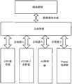
图1为本发明的数字化数据采样装置内部结构图;Fig. 1 is the internal structure diagram of digitized data sampling device of the present invention;
图2为本发明的数字化数据采样装置插件结构图。Fig. 2 is a structural diagram of the plug-in of the digital data sampling device of the present invention.
具体实施方式Detailed ways
本装置主要有AC采样板、FT3串口采样板、Power电源板、CPU板、总线通信背板、液晶显示板。AC板和FT3串口板用来进行数据采样,总线背板用来接入其它板件并实现板件间的总线通信,Power电源板为装置提供电源,CPU板负责数据的处理及组织报文,同时接收IEEE1588对时,向交换机发送GMRP报文用以动态建立VLAN。同时CPU板上还预留有2个网络端口,用来通过GOOSE发送装置的状态及告警信息。整个装置的具体实现流程如下:This device mainly includes AC sampling board, FT3 serial port sampling board, Power board, CPU board, bus communication back board, liquid crystal display board. The AC board and the FT3 serial board are used for data sampling, the bus backplane is used to connect to other boards and realize the bus communication between the boards, the Power board provides power for the device, and the CPU board is responsible for data processing and organizing messages. At the same time, it receives IEEE1588 timing and sends GMRP message to the switch to dynamically establish VLAN. At the same time, 2 network ports are reserved on the CPU board, which are used to send device status and alarm information through GOOSE. The specific implementation process of the whole device is as follows:
装置上电后首先读取配置文件。配置文件分为装置配置文件和9-2报文配置文件两个。装置配置文件用来配置装置的基本参数,如电压电流的一次额定值,串口晶振频率、网口有效标志及通信参数等;9-2报文配置文件用来配置9-2报文所包含的数据属性、目的地址、应用标示等配置信息。若相关的参数配置不正确或者未配置,装置会进行相应的报错处理。因此,配置文件的正确配置以及装置的正确读取是保证装置正常运行的前提。After the device is powered on, the configuration file is first read. Configuration files are divided into device configuration files and 9-2 message configuration files. The device configuration file is used to configure the basic parameters of the device, such as the primary rated value of the voltage and current, the frequency of the serial port crystal oscillator, the valid flag of the network port, and the communication parameters, etc.; the 9-2 message configuration file is used to configure the parameters contained in the 9-2 message. Configuration information such as data attributes, destination addresses, and application labels. If the relevant parameters are configured incorrectly or not configured, the device will report a corresponding error. Therefore, the correct configuration of the configuration file and the correct reading of the device are the prerequisites to ensure the normal operation of the device.
装置采样接收。针对AC板,装置通过中断定时读取采样AD芯片的数据。整个AC采样板能够接入保护的三相电压、电流,测量的三相电流以及保护用的中性点电压等。针对FT3串口采样板,具有7路串口信息,用来接入变电站一个间隔的4路电压和3路电流。装置晶振定时发送采样脉冲,电子式互感器在接收到采样脉冲后将采样数据按照FT3的格式发送给采样装置,整个采样频率由晶振来控制。当装置仅接入一种板件的时候,采样数据按照各自的点号进行处理,当AC板和FT3板同时使用的时候,由于串口通信存在的延迟,根据不同厂家的电子式互感器,存在1-2个点的采样延迟,此时采样数据的点号要以电子式互感器的为准,即电子式互感器的当前采样点与AD采样的前一个或者两个点为组进行后续报文的处理。The device sample is received. For the AC board, the device regularly reads the data of the sampling AD chip through interrupts. The entire AC sampling board can be connected to the protected three-phase voltage and current, the measured three-phase current and the neutral point voltage for protection. For the FT3 serial port sampling board, it has 7 channels of serial port information, which are used to access 4 channels of voltage and 3 channels of current in one interval of the substation. The crystal oscillator of the device sends sampling pulses regularly, and the electronic transformer sends the sampling data to the sampling device in the format of FT3 after receiving the sampling pulses. The entire sampling frequency is controlled by the crystal oscillator. When the device is only connected to one type of board, the sampling data is processed according to their respective point numbers. When the AC board and FT3 board are used at the same time, due to the delay in serial communication, according to the electronic transformers of different manufacturers, there are Sampling delay of 1-2 points. At this time, the point number of the sampling data should be based on the electronic transformer, that is, the current sampling point of the electronic transformer and the previous one or two points of AD sampling are used as a group for follow-up reporting. text processing.
装置报文的处理。数据到达报文处理流程后首先会对数据是否溢出以及是否有效进行判断,并对每个数据的品质进行置位,以表示数据的有效性。然后将数据按照IEC61850-9-2标准的要求,将电压V转变成1mV,电流A转变成10mA。接着报文处理流程会进行报文的组包,此时会根据9-2报文的配置要求组织报文,因此整个9-2报文的长度和数据个数是灵活可变的。最后将采样数据按照9-2报文配置文件中数据的配置顺序进行填放,最后交给底层的发送函数进行报文的发送处理。底层的发送函数也会根据装置的基本配置将相应的一个或者多个9-2报文通过一个或者多个网口进行发送。Device message processing. After the data arrives in the message processing flow, it will first judge whether the data is overflowing and whether it is valid, and set the quality of each data to indicate the validity of the data. Then the data is converted into 1mV for voltage V and 10mA for current A according to the requirements of the IEC61850-9-2 standard. Then the message processing flow will carry out the grouping of the message, and at this time, the message will be organized according to the configuration requirements of the 9-2 message, so the length and the number of data of the entire 9-2 message are flexible and variable. Finally, the sampling data is filled in according to the data configuration sequence in the 9-2 message configuration file, and finally handed over to the underlying sending function for message sending processing. The underlying sending function will also send corresponding one or more 9-2 messages through one or more network ports according to the basic configuration of the device.
装置的对时处理。由于本装置能够接收IEEE1588对时,因此,其对时处理也是较为复杂。整个对时过程是通过多次交互来实现。首先主时钟每隔2s向其发送对时报文,采样装置在第一次接收到对时报文后对时就开始了。通过多次不断的调整,最终装置的时间和主时钟之间的时间误差会降低到1us以下。目前整个装置的对时精度可以控制在400ns左右。Device timing processing. Since the device can receive IEEE1588 time synchronization, its time synchronization processing is relatively complicated. The entire time synchronization process is realized through multiple interactions. First, the master clock sends a time synchronization message to it every 2s, and the sampling device starts time synchronization after receiving the time synchronization message for the first time. Through multiple continuous adjustments, the time error between the time of the final device and the main clock will be reduced to less than 1us. At present, the timing accuracy of the whole device can be controlled at about 400ns.
GMRP报文的处理。为有效降低全站采样网络的通信流量,有效减少通信延迟,每个采样装置定时都会向交换机发送GMRP报文,报文中包含需要采样装置采样数据的设备的MAC地址,交换机在收到这些报文后就将相应的报文转发到接入该设备的端口,从而有效降低了端口通信流量,实现全站VLAN的动态控制。Processing of GMRP packets. In order to effectively reduce the communication traffic of the sampling network in the whole station and effectively reduce the communication delay, each sampling device will send GMRP messages to the switch at regular intervals. Then the corresponding message is forwarded to the port connected to the device, thereby effectively reducing the communication flow of the port and realizing the dynamic control of VLAN in the whole station.
GOOSE报文发送处理。CPU板预留的两个网口用来实现装置状态及告警信息的上送。当采样芯片异常、电源异常或者通信异常的时候,CPU板能够及时将故障信息上送到接收装置或者后台监控系统以及调度终端,进而对采样异常的原因进行定位和分析,便于及时采取相应的补救措施。如此方式能够对装置的整个运行状态进行实时监控,有利于全站的运行管理和维护。GOOSE message sending processing. The two network ports reserved on the CPU board are used to send device status and alarm information. When the sampling chip is abnormal, the power supply is abnormal, or the communication is abnormal, the CPU board can promptly send the fault information to the receiving device or the background monitoring system and dispatching terminal, and then locate and analyze the cause of the sampling abnormality, so as to take corresponding remedies in time measure. In this way, the entire operating status of the device can be monitored in real time, which is beneficial to the operation management and maintenance of the whole station.
装置的液晶面板主要是用来显示装置的采样数据,同时用来查看装置的配置参数,故障信息记录等信息。整个液晶板与总线板相互独立,彼此之间通过总线进行通信。The LCD panel of the device is mainly used to display the sampling data of the device, and at the same time to view the configuration parameters of the device, fault information records and other information. The entire liquid crystal panel and the bus panel are independent of each other, and communicate with each other through the bus.
以上已以较佳实施例公开了本发明,然其并非用以限制本发明,凡采用等同替换或者等效变换方式所获得的技术方案,均落在本发明的保护范围之内。The above has disclosed the present invention with preferred embodiments, but it is not intended to limit the present invention, and all technical solutions obtained by adopting equivalent replacement or equivalent transformation methods fall within the protection scope of the present invention.
Claims (8)
Priority Applications (1)
| Application Number | Priority Date | Filing Date | Title |
|---|---|---|---|
| CN 201010256490CN101951024B (en) | 2010-08-18 | 2010-08-18 | Digital data acquisition device |
Applications Claiming Priority (1)
| Application Number | Priority Date | Filing Date | Title |
|---|---|---|---|
| CN 201010256490CN101951024B (en) | 2010-08-18 | 2010-08-18 | Digital data acquisition device |
Publications (2)
| Publication Number | Publication Date |
|---|---|
| CN101951024Atrue CN101951024A (en) | 2011-01-19 |
| CN101951024B CN101951024B (en) | 2013-04-10 |
Family
ID=43454415
Family Applications (1)
| Application Number | Title | Priority Date | Filing Date |
|---|---|---|---|
| CN 201010256490ActiveCN101951024B (en) | 2010-08-18 | 2010-08-18 | Digital data acquisition device |
Country Status (1)
| Country | Link |
|---|---|
| CN (1) | CN101951024B (en) |
Cited By (9)
| Publication number | Priority date | Publication date | Assignee | Title |
|---|---|---|---|---|
| CN102231568A (en)* | 2011-07-05 | 2011-11-02 | 国电南瑞科技股份有限公司 | Multifunctional intelligent data collecting device |
| CN102611030A (en)* | 2012-03-15 | 2012-07-25 | 邯郸供电公司 | Two-dimensional code state display instrument of intelligent equipment of transformer substation |
| CN102882626A (en)* | 2012-10-24 | 2013-01-16 | 南京澳德思电气有限公司 | B code decoding technology fused institute of electrical and electronic engineers 1588 (IEEE1588) intelligent power grid time transmission method and device |
| CN103034206A (en)* | 2012-12-14 | 2013-04-10 | 昆明理工大学 | Industrial data collection system adopting late binding communication plug-in unit |
| CN103200280A (en)* | 2013-02-20 | 2013-07-10 | 中国电力科学研究院 | Process level interface device of intelligent substation |
| CN104538163A (en)* | 2014-12-09 | 2015-04-22 | 许继电气股份有限公司 | Mutual inductor collection device |
| WO2015070707A1 (en)* | 2013-11-13 | 2015-05-21 | 国家电网公司 | Method for acquiring universal data of intelligent substation |
| CN107255758A (en)* | 2017-06-02 | 2017-10-17 | 中国电力科学研究院 | A kind of broadband multi-frequency electrical quantity unified measurement analysis system and implementation method |
| CN113542043A (en)* | 2020-04-14 | 2021-10-22 | 中兴通讯股份有限公司 | Data sampling method, device, device and medium for network equipment |
Citations (3)
| Publication number | Priority date | Publication date | Assignee | Title |
|---|---|---|---|---|
| CN101498757A (en)* | 2009-03-06 | 2009-08-05 | 深圳市双合电脑系统股份有限公司 | Real-time dynamic monitoring and recording equipment of power system |
| CN101650548A (en)* | 2009-08-31 | 2010-02-17 | 江苏方天电力技术有限公司 | Time setting device for digital substation |
| CN101789627A (en)* | 2010-01-06 | 2010-07-28 | 江苏方天电力技术有限公司 | High-precision Ethernet timing device |
- 2010
- 2010-08-18CNCN 201010256490patent/CN101951024B/enactiveActive
Patent Citations (3)
| Publication number | Priority date | Publication date | Assignee | Title |
|---|---|---|---|---|
| CN101498757A (en)* | 2009-03-06 | 2009-08-05 | 深圳市双合电脑系统股份有限公司 | Real-time dynamic monitoring and recording equipment of power system |
| CN101650548A (en)* | 2009-08-31 | 2010-02-17 | 江苏方天电力技术有限公司 | Time setting device for digital substation |
| CN101789627A (en)* | 2010-01-06 | 2010-07-28 | 江苏方天电力技术有限公司 | High-precision Ethernet timing device |
Cited By (14)
| Publication number | Priority date | Publication date | Assignee | Title |
|---|---|---|---|---|
| CN102231568A (en)* | 2011-07-05 | 2011-11-02 | 国电南瑞科技股份有限公司 | Multifunctional intelligent data collecting device |
| CN102611030A (en)* | 2012-03-15 | 2012-07-25 | 邯郸供电公司 | Two-dimensional code state display instrument of intelligent equipment of transformer substation |
| CN102882626A (en)* | 2012-10-24 | 2013-01-16 | 南京澳德思电气有限公司 | B code decoding technology fused institute of electrical and electronic engineers 1588 (IEEE1588) intelligent power grid time transmission method and device |
| CN103034206A (en)* | 2012-12-14 | 2013-04-10 | 昆明理工大学 | Industrial data collection system adopting late binding communication plug-in unit |
| CN103200280A (en)* | 2013-02-20 | 2013-07-10 | 中国电力科学研究院 | Process level interface device of intelligent substation |
| CN103200280B (en)* | 2013-02-20 | 2016-09-21 | 中国电力科学研究院 | Transformer station process layer interface equipment |
| WO2015070707A1 (en)* | 2013-11-13 | 2015-05-21 | 国家电网公司 | Method for acquiring universal data of intelligent substation |
| CN104538163A (en)* | 2014-12-09 | 2015-04-22 | 许继电气股份有限公司 | Mutual inductor collection device |
| CN104538163B (en)* | 2014-12-09 | 2018-04-06 | 许继电气股份有限公司 | A kind of transformer harvester |
| CN107255758A (en)* | 2017-06-02 | 2017-10-17 | 中国电力科学研究院 | A kind of broadband multi-frequency electrical quantity unified measurement analysis system and implementation method |
| CN107255758B (en)* | 2017-06-02 | 2021-03-23 | 中国电力科学研究院 | Broadband multi-frequency electric quantity unified measurement and analysis system and implementation method |
| CN113542043A (en)* | 2020-04-14 | 2021-10-22 | 中兴通讯股份有限公司 | Data sampling method, device, device and medium for network equipment |
| CN113542043B (en)* | 2020-04-14 | 2024-06-07 | 中兴通讯股份有限公司 | Data sampling method, device, equipment and medium for network equipment |
| US12348395B2 (en) | 2020-04-14 | 2025-07-01 | Zte Corporation | Data sampling method for a network device, device, and medium |
Also Published As
| Publication number | Publication date |
|---|---|
| CN101951024B (en) | 2013-04-10 |
Similar Documents
| Publication | Publication Date | Title |
|---|---|---|
| CN101951024B (en) | Digital data acquisition device | |
| CN106059067B (en) | A kind of remote monitoring system of electric power system | |
| CN102768705B (en) | IEC (International Electrotechnical Commission) 61968-based power distribution network model interoperation and functional verification method | |
| CN103200280B (en) | Transformer station process layer interface equipment | |
| CN103995193B (en) | Digital transformer substation is stood electric energy quality on-line monitoring device entirely | |
| CN106066192A (en) | A kind of low-voltage platform area fault diagnosis system | |
| CN110311711A (en) | An interaction method between intelligent distribution transformer terminal and smart meter based on HPLC communication channel | |
| CN101895152B (en) | Intelligent interface device of digital transformer substation switch | |
| CN106160227A (en) | A kind of intelligent substation entirely stand communication network unified management method | |
| CN105186697A (en) | Remote diagnosis system of IED operating conditions of IEC61850 intelligent substation | |
| CN114726097A (en) | Two-core mode low-voltage intelligent circuit breaker device | |
| CN104009540B (en) | The comprehensive power monitoring system of a kind of metro traction electric substation and monitoring method | |
| CN101964548A (en) | Comprehensive intelligent assembly of power transformer | |
| CN111030910A (en) | Ring network node communication state monitoring method, system, measurement and control device and local module | |
| CN103178542B (en) | Control method of distributed power grid-connection interface system | |
| CN104135066B (en) | Intelligent substation system | |
| CN109633345A (en) | A kind of secondary device on-line monitoring and analytical equipment | |
| CN102832708A (en) | Intelligent transformer substation based on integrated multi-stage server framework | |
| CN102694418B (en) | Alternating-current distribution intelligent monitoring system | |
| CN202197108U (en) | Intelligent integrated reactive power compensation device | |
| CN201608563U (en) | Electric arc light intelligent remote monitoring system | |
| CN203289496U (en) | Intelligent substationprocess layer interface device | |
| CN103516055B (en) | The monitoring method of Intelligent substation merging unit state | |
| CN105141035B (en) | Process layer devices data collection and control system | |
| Xie et al. | Low Voltage Distribution Network Data Sensing and Fault Analysis System |
Legal Events
| Date | Code | Title | Description |
|---|---|---|---|
| C06 | Publication | ||
| PB01 | Publication | ||
| C10 | Entry into substantive examination | ||
| SE01 | Entry into force of request for substantive examination | ||
| C14 | Grant of patent or utility model | ||
| GR01 | Patent grant | ||
| ASS | Succession or assignment of patent right | Owner name:NARI NANJING CONTROL SYSTEM LTD. Effective date:20141128 | |
| C41 | Transfer of patent application or patent right or utility model | ||
| TR01 | Transfer of patent right | Effective date of registration:20141128 Address after:High road high tech Development Zone Nanjing city Jiangsu province 210061 No. 20 Patentee after:NARI Technology Development Co., Ltd. Patentee after:SGCC NARI Nanjing Control System Co., Ltd. Address before:High road high tech Development Zone Nanjing city Jiangsu province 210061 No. 20 Patentee before:NARI Technology Development Co., Ltd. |