CN101951011B - Solar photovoltaic and commercial power combined power supply system and control method thereof - Google Patents
Solar photovoltaic and commercial power combined power supply system and control method thereofDownload PDFInfo
- Publication number
- CN101951011B CN101951011BCN2010102630337ACN201010263033ACN101951011BCN 101951011 BCN101951011 BCN 101951011BCN 2010102630337 ACN2010102630337 ACN 2010102630337ACN 201010263033 ACN201010263033 ACN 201010263033ACN 101951011 BCN101951011 BCN 101951011B
- Authority
- CN
- China
- Prior art keywords
- output
- photovoltaic array
- circuit
- voltage
- converter
- Prior art date
- Legal status (The legal status is an assumption and is not a legal conclusion. Google has not performed a legal analysis and makes no representation as to the accuracy of the status listed.)
- Expired - Fee Related
Links
Images


Classifications
- Y—GENERAL TAGGING OF NEW TECHNOLOGICAL DEVELOPMENTS; GENERAL TAGGING OF CROSS-SECTIONAL TECHNOLOGIES SPANNING OVER SEVERAL SECTIONS OF THE IPC; TECHNICAL SUBJECTS COVERED BY FORMER USPC CROSS-REFERENCE ART COLLECTIONS [XRACs] AND DIGESTS
- Y02—TECHNOLOGIES OR APPLICATIONS FOR MITIGATION OR ADAPTATION AGAINST CLIMATE CHANGE
- Y02B—CLIMATE CHANGE MITIGATION TECHNOLOGIES RELATED TO BUILDINGS, e.g. HOUSING, HOUSE APPLIANCES OR RELATED END-USER APPLICATIONS
- Y02B70/00—Technologies for an efficient end-user side electric power management and consumption
- Y02B70/10—Technologies improving the efficiency by using switched-mode power supplies [SMPS], i.e. efficient power electronics conversion e.g. power factor correction or reduction of losses in power supplies or efficient standby modes
- Y—GENERAL TAGGING OF NEW TECHNOLOGICAL DEVELOPMENTS; GENERAL TAGGING OF CROSS-SECTIONAL TECHNOLOGIES SPANNING OVER SEVERAL SECTIONS OF THE IPC; TECHNICAL SUBJECTS COVERED BY FORMER USPC CROSS-REFERENCE ART COLLECTIONS [XRACs] AND DIGESTS
- Y02—TECHNOLOGIES OR APPLICATIONS FOR MITIGATION OR ADAPTATION AGAINST CLIMATE CHANGE
- Y02E—REDUCTION OF GREENHOUSE GAS [GHG] EMISSIONS, RELATED TO ENERGY GENERATION, TRANSMISSION OR DISTRIBUTION
- Y02E10/00—Energy generation through renewable energy sources
- Y02E10/50—Photovoltaic [PV] energy
- Y02E10/56—Power conversion systems, e.g. maximum power point trackers
- Y—GENERAL TAGGING OF NEW TECHNOLOGICAL DEVELOPMENTS; GENERAL TAGGING OF CROSS-SECTIONAL TECHNOLOGIES SPANNING OVER SEVERAL SECTIONS OF THE IPC; TECHNICAL SUBJECTS COVERED BY FORMER USPC CROSS-REFERENCE ART COLLECTIONS [XRACs] AND DIGESTS
- Y02—TECHNOLOGIES OR APPLICATIONS FOR MITIGATION OR ADAPTATION AGAINST CLIMATE CHANGE
- Y02P—CLIMATE CHANGE MITIGATION TECHNOLOGIES IN THE PRODUCTION OR PROCESSING OF GOODS
- Y02P80/00—Climate change mitigation technologies for sector-wide applications
- Y02P80/10—Efficient use of energy, e.g. using compressed air or pressurized fluid as energy carrier
Landscapes
- Dc-Dc Converters (AREA)
- Control Of Electrical Variables (AREA)
Abstract
Description
Translated fromChinese技术领域technical field
本发明涉及一种供电系统,尤其涉及一种太阳能光伏阵列与市电联合的供电系统及其供电控制方法,属于新能源供电系统领域。 The invention relates to a power supply system, in particular to a power supply system combined with a solar photovoltaic array and mains power and a power supply control method thereof, belonging to the field of new energy power supply systems. the
背景技术Background technique
随着人类生活水平的不断提高,对能源的需求大幅度增加。化石能源作为不可再生能源正日益枯竭,而且它所造成的环境污染日益严重。太阳能光伏供电作为绿色新能源供电方式,其得到了越来越多的应用。它最大的优点是可以再生,对环境没有污染。 With the continuous improvement of human living standards, the demand for energy has increased significantly. As a non-renewable energy source, fossil energy is becoming increasingly exhausted, and the environmental pollution it causes is becoming increasingly serious. As a green new energy power supply method, solar photovoltaic power supply has been more and more applied. Its biggest advantage is that it can be regenerated and has no pollution to the environment. the
太阳能光伏电池的最大特性是外特性曲线随光强和温度的变化而变化,为了能够最大限度地利用太阳能,要求直流变换器能时刻控制太阳能光伏电池的输出,使其工作在最大功率点附近。 The biggest characteristic of solar photovoltaic cells is that the external characteristic curve changes with light intensity and temperature. In order to maximize the use of solar energy, the DC converter is required to control the output of solar photovoltaic cells at all times to make it work near the maximum power point. the
目前提出的太阳能供电系统无法保证负载能持续稳定地工作,因此为了能够充分地使用太阳能,同时又需要保证负载能够时刻正常稳定地工作,所以必须加入一辅助电源,以在太阳能光伏无法满足负载供电需要时作为备用。 The currently proposed solar power supply system cannot guarantee the continuous and stable operation of the load. Therefore, in order to fully use the solar energy and at the same time ensure that the load can work normally and stably at all times, an auxiliary power supply must be added to supply power to the load when the solar photovoltaic cannot meet the requirements. As a backup when needed. the
发明内容Contents of the invention
本发明的目的在于:提出一种以太阳能光伏为主供电电源、市电电源为辅助电源的联合供电系统及其联合供电控制方法。 The object of the present invention is to propose a joint power supply system and its joint power supply control method with solar photovoltaic as the main power supply and mains power as the auxiliary power supply. the
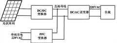
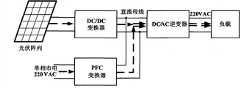
本发明供电系统包括光伏阵列、市电电源、DC/DC变换器、PFC变换器和DC/AC逆变器,其中:光伏阵列的输出通过DC/DC变换器接入直流母线,市电电源的输出通过PFC变换器接入直流母线,DC/AC逆变器的输入端连入直流母线,DC/AC逆变器的输出连接负载。 The power supply system of the present invention includes a photovoltaic array, a mains power supply, a DC/DC converter, a PFC converter and a DC/AC inverter, wherein: the output of the photovoltaic array is connected to the DC bus through the DC/DC converter, and the mains power supply The output is connected to the DC bus through the PFC converter, the input of the DC/AC inverter is connected to the DC bus, and the output of the DC/AC inverter is connected to the load. the
所述DC/DC变换器是由Boost电路、全桥变换器和整流滤波电路依次串接组成,Boost电路的输入连接光伏阵列的输出,整流滤波电路的输出接入直流母线。 The DC/DC converter is composed of a Boost circuit, a full-bridge converter and a rectification and filtering circuit connected in series in sequence. The input of the Boost circuit is connected to the output of the photovoltaic array, and the output of the rectification and filtering circuit is connected to the DC bus. the
所述PFC变换器是由PFC整流电路连接Boost PFC电路组成,PFC整流电路的输入连接市电电源的输出,Boost PFC电路的输出接入直流母线。 The PFC converter is composed of a PFC rectifier circuit connected to a Boost PFC circuit, the input of the PFC rectifier circuit is connected to the output of the mains power supply, and the output of the Boost PFC circuit is connected to the DC bus. the
基于本发明供电系统的供电控制方法,该控制方法所采用的控制电路分为两路,具体为: Based on the power supply control method of the power supply system of the present invention, the control circuit adopted by the control method is divided into two circuits, specifically:
光伏阵列输出电流、电压采样接入MPPT控制器,MPPT控制器的输出接入加法器,加 法器的输出与光伏阵列输出电流采样接入第一减法器,第一减法器的输出依次通过第一电流调节器、第一PWM电路和第一门极驱动电路后连接Boost开关管;电压比较器参考值与直流母线输出电压采样接入第二减法器,第二减法器的输出接入电压调节器,电压调节器的一路输出与正弦馒头波接入乘法器,另一路输出通过阻断二极管接入加法器,乘法器的输出与PFC变换器电感电流采样接入第三减法器,第三减法器的输出依次通过第二电流调节器、第二PWM电路和第二门极驱动电路后连接Boost PFC开关管; The output current and voltage sampling of the photovoltaic array is connected to the MPPT controller, the output of the MPPT controller is connected to the adder, the output of the adder and the output current sampling of the photovoltaic array are connected to the first subtractor, and the output of the first subtractor passes through the first subtractor in turn. A current regulator, the first PWM circuit and the first gate drive circuit are connected to the Boost switching tube; the reference value of the voltage comparator and the output voltage sampling of the DC bus are connected to the second subtractor, and the output of the second subtractor is connected to the voltage regulator One output of the voltage regulator and the sinusoidal steamed bread wave are connected to the multiplier, the other output is connected to the adder through the blocking diode, the output of the multiplier and the PFC converter inductor current sampling are connected to the third subtractor, and the third subtraction The output of the converter passes through the second current regulator, the second PWM circuit and the second gate drive circuit in turn, and then connects to the Boost PFC switch tube;
该控制方法包括如下内容: The control method includes the following contents:
当光伏阵列的最大输出功率大于负载所需功率时,由光伏阵列单独向负载供电,直流母线电压升高,使电压调节器的输出为负,Boost PFC开关管的占空比为0,同时使阻断二极管导通,电压调节器的输出作为调整信号使MPPT控制器中电压给定参考值减小,此时电压调节器与第一电流调节器组成双闭环,使直流母线稳压,处于稳压状态; When the maximum output power of the photovoltaic array is greater than the power required by the load, the photovoltaic array supplies power to the load alone, and the DC bus voltage rises, making the output of the voltage regulator negative, and the duty cycle of the Boost PFC switch is 0. The blocking diode is turned on, and the output of the voltage regulator is used as an adjustment signal to reduce the given reference value of the voltage in the MPPT controller. At this time, the voltage regulator and the first current regulator form a double closed loop to stabilize the DC bus voltage. pressure state;
当光伏阵列的最大输出功率小于负载所需功率时,由光伏阵列和市电电源同时向负载供电,此时电压调节器调节Boost PFC开关管的占空比控制直流母线电压,阻断二极管阻断,两路控制电路独立工作,MPPT控制器计算得到的光伏阵列最大功率点电压值作为第一电流调节器的基准给定,使光伏阵列输出最大功率,不足功率由市电电源提供; When the maximum output power of the photovoltaic array is less than the power required by the load, the photovoltaic array and the mains supply power to the load at the same time. At this time, the voltage regulator adjusts the duty cycle of the Boost PFC switch to control the DC bus voltage, and the blocking diode blocks , the two control circuits work independently, the maximum power point voltage value of the photovoltaic array calculated by the MPPT controller is used as the reference of the first current regulator, so that the photovoltaic array outputs the maximum power, and the insufficient power is provided by the mains power supply;
当光伏阵列无法工作时,关闭DC/DC变换器,由市电电源向负载供电,电压调节器调节Boost PFC开关管的占空比控制直流母线电压,使直流母线电压恒定。 When the photovoltaic array fails to work, the DC/DC converter is turned off, and the load is supplied by the mains power supply. The voltage regulator adjusts the duty cycle of the Boost PFC switch tube to control the DC bus voltage to keep the DC bus voltage constant. the
本发明供电系统以光伏阵列为主要供电电源,根据太阳能光伏电池输出功率的多少,来控制本系统在三种模式下平稳切换,即太阳能单路独立工作、市电单路独立工作、太阳能/市电两路联合工作模式,实现尽可能地利用太阳能,在太阳能不足的情况下以市电辅助供电,保证负载能持续稳定地工作。 The power supply system of the present invention uses the photovoltaic array as the main power supply, and controls the stable switching of the system in three modes according to the output power of the solar photovoltaic cells, that is, the solar single-channel independent work, the mains single-channel independent work, the solar/city The joint working mode of the two circuits of electricity realizes the use of solar energy as much as possible, and in the case of insufficient solar energy, the utility power is used as an auxiliary power supply to ensure that the load can continue to work stably. the
附图说明Description of drawings
图1为本发明供电系统的结构框图。 Fig. 1 is a structural block diagram of the power supply system of the present invention. the
图2为本发明供电系统的电路原理图。 Fig. 2 is a schematic circuit diagram of the power supply system of the present invention. the
图3~图5分别为本发明供电系统的三种工作模态能量流动示意图。 3 to 5 are respectively schematic diagrams of energy flow in three working modes of the power supply system of the present invention. the
图6为本发明供电系统的控制电路结构示意图。 Fig. 6 is a schematic structural diagram of the control circuit of the power supply system of the present invention. the
图7~图9分别为本发明供电系统控制电路的三种工作模态示意图。 7 to 9 are respectively schematic diagrams of three working modes of the control circuit of the power supply system of the present invention. the
上述附图中的主要标号名称:PV为光伏阵列;Vg为电网电压(市电输入电压);Cin1为输入滤波电容;Lf1、Lf2、Lf3、Lf4均为滤波电感;Q1为Boost开关管;Q2为Boost PFC开关管; Tr为隔离变压器;Rld为负载;Vo为系统输出电压;ipv_f为光伏阵列输出电流采样;vpv_f为光伏阵列输出电压采样;vo_f为直流母线输出电压采样;iin2_f为PFC变换器电感电流采样;iin1_ref、iin2_ref分别为第一、第二电流比较器参考值;QD1为Boost开关管(Q1)的驱动信号;QD2为Boost PFC(Q2)的驱动信号。 The main label names in the above drawings: PV is the photovoltaic array; Vg is the grid voltage (mains input voltage); Cin1 is the input filter capacitor; Lf1 , Lf2 , Lf3 , and Lf4 are all filter inductors; Q1 is the Boost switching tube; Q2 is the Boost PFC switching tube; Tr is the isolation transformer; Rld is the load; Vo is the system output voltage; ipv_f is the sampling of the output current of the photovoltaic array; vpv_f is the sampling of the output voltage of the photovoltaic array; vo_f is the DC bus output voltage sampling; iin2_f is the PFC converter inductor current sampling; iin1_ref and iin2_ref are the reference values of the first and second current comparators respectively; QD1 is the driving signal of the Boost switch (Q1 ) ; QD2 is the driving signal of Boost PFC (Q2 ).
具体实施方式Detailed ways
本发明供电系统的结构如图1所示,包括光伏阵列、市电电源、DC/DC变换器、PFC(功率因数校正)变换器和DC/AC逆变器,其中:光伏阵列的输出通过DC/DC变换器接入直流母线,市电电源的输出通过PFC变换器接入直流母线,DC/AC逆变器的输入端连入直流母线,DC/AC逆变器的输出给交流负载供电。 The structure of the power supply system of the present invention is shown in Figure 1, including a photovoltaic array, a mains power supply, a DC/DC converter, a PFC (power factor correction) converter and a DC/AC inverter, wherein: the output of the photovoltaic array is passed through DC The /DC converter is connected to the DC bus, the output of the mains power is connected to the DC bus through the PFC converter, the input end of the DC/AC inverter is connected to the DC bus, and the output of the DC/AC inverter supplies power to the AC load. the
本发明供电系统的具体电路如图2所示。DC/DC变换器是由Boost电路1、全桥变换器2和整流滤波电路3依次串接组成;PFC变换器是由PFC整流电路4连接Boost PFC电路5组成;DC/AC逆变器是由逆变电路6连接滤波输出电路7组成。其中:Boost电路1并联在光伏阵列PV的正负输出端上;全桥变换器2由开关管QR1、QR3串联组成的超前桥臂与开关管QR2、QR4串联组成的滞后桥臂并联组成,隔离变压器Tr的原边两端分别与超前和滞后两桥臂的开关管的串联结点相连接,其副边的同名端与整流滤波电路3的两个二极管DB1、DB3的串联结点相连接,异名端与另两个二极管DB2、DB4的串联结点相连接;整流滤波电路3的结构为:两个二极管DB1、DB3串联组成的串联支路与另两个二极管DB2、DB4串联组成的串联支路并联,滤波电感Lf3与滤波电容Cf3串联后与二极管串联支路并联;PFC整流电路4的结构为:两个二极管DB5、DB7串联组成的串联支路与另两个二极管DB6、DB8串联组成的串联支路并联;Boost PFC电路5由滤波电感Lf2、Boost PFC开关管Q2、续流二极管D2、滤波电容Cf2组成;逆变电路6由开关管QR5、QR7串联组成的超前桥臂与开关管QR6、QR8串联组成的滞后桥臂并联组成;滤波输出电路7是由滤波电感Lf4、滤波电容Cf4及负载Rld组成。上述开关管QR1~QR8我们采用MOSFET,其均带有寄生体二极管。 The specific circuit of the power supply system of the present invention is shown in FIG. 2 . The DC/DC converter is composed of Boost circuit 1, full bridge converter 2 and rectification filter circuit 3 connected in series; the PFC converter is composed of PFC rectifier circuit 4 connected to Boost PFC circuit 5; the DC/AC inverter is composed of The inverter circuit 6 is connected to the filter output circuit 7 to form. Among them: Boost circuit 1 is connected in parallel to the positive and negative output ends of the photovoltaic array PV; full-bridge converter 2 is a leading bridge arm composed of switching tubes QR1 and QR3 connected in series, and a lagging bridge arm composed of switching tubes QR2 and QR4 connected in series Composed in parallel, the two ends of the primary side of the isolation transformer Tr are respectively connected to the series nodes of the switching tubes of the leading and lagging two bridge arms, and the same-named terminal of the secondary side is connected to the two diodes DB1 and DB3 of the rectifying and filtering circuit 3 The series node of the diodesDB2 and DB4 is connected to each other, and the opposite end is connected to the series nodes of the other two diodes DB2 and DB4 ; The other two diodes DB2 , DB4 are connected in parallel in series, and the filter inductance Lf3 and filter capacitor Cf3 are connected in parallel with the diode series branch; the structure of the PFC rectifier circuit 4 is: two diodes DB5 , D The series branch composed ofB7 in series is connected in parallel with the series branch composed of the other two diodes DB6 and DB8 connected in series; Boost PFC circuit 5 consists of filter inductor Lf2 , Boost PFC switch tube Q2 , freewheeling diode D2 , filter capacitor Composedof Cf2 ; the inverter circuit 6 is composed of the leading bridge arm formed by the series connection of the switch tubes QR5 and QR7 and the parallel connection of the lagging bridge arm formed by the series connection of the switch tubes QR6 and QR8 ; The filter capacitor Cf4 and the load Rld are composed. We use MOSFETs for the above switching tubes QR1 -QR8 , all of which have parasitic body diodes.
为了充分利用太阳能、最大限度发挥光伏阵列的效用,必须使光伏阵列时刻工作在最大功率点处,即需要采用最大功率点跟踪技术。目前的太阳能电池最大功率点跟踪技术控制算法有很多种,本发明采用扰动观察法(Perturbation & Observation,P&O)。 In order to make full use of solar energy and maximize the effectiveness of the photovoltaic array, the photovoltaic array must always work at the maximum power point, that is, the maximum power point tracking technology is required. There are many kinds of control algorithms for the current maximum power point tracking technology of solar cells, and the present invention adopts the method of perturbation and observation (Perturbation & Observation, P&O). the
下面根据光伏阵列的输出功率及负载大小,并结合图3~图5叙述本发明供电系统的三种工作模态能量流动情况。 According to the output power of the photovoltaic array and the size of the load, the energy flow of the three working modes of the power supply system of the present invention will be described in conjunction with FIGS. 3 to 5 . the
系统工作模式1[如图3所示]:光伏阵列的最大输出功率大于负载所需功率,控制DC/DC 变换器工作在输入为恒压状态,光伏阵列单独提供负载所需功率,PFC变换器不工作。 System working mode 1 [as shown in Figure 3]: the maximum output power of the photovoltaic array is greater than the power required by the load, and the DC/DC converter is controlled to work in a state of constant input voltage. The photovoltaic array alone provides the power required by the load, and the PFC converter Not working. the
系统工作模式2[如图4所示]:光伏阵列的最大输出功率小于负载所需功率,控制DC/DC变换器工作在MPPT(Maximum Power Point Tracking,MPPT,最大功率点跟踪)状态,同时PFC变换器工作,市电电源提供负载所需剩余功率。 System working mode 2 [as shown in Figure 4]: the maximum output power of the photovoltaic array is less than the power required by the load, and the DC/DC converter is controlled to work in the MPPT (Maximum Power Point Tracking, MPPT, maximum power point tracking) state, while the PFC The converter works, and the mains supply provides the remaining power required by the load. the
系统工作模式3[如图5所示]:光伏阵列无法正常工作,关闭DC/DC变换器,PFC变换器独立工作,由市电单独提供负载所需功率。 System working mode 3 [as shown in Figure 5]: The photovoltaic array cannot work normally, the DC/DC converter is turned off, the PFC converter works independently, and the power required by the load is provided by the mains alone. the
本发明的目的是在保证负载时刻正常工作的情况下最大限度地使用太阳能,这就需要对整个系统的能量进行管理。本发明供电系统的控制电路结构如图6所示,具体结构如下: The purpose of the present invention is to maximize the use of solar energy while ensuring the normal operation of loads at all times, which requires energy management of the entire system. The control circuit structure of the power supply system of the present invention is shown in Figure 6, and the specific structure is as follows:
光伏阵列输出电流、电压采样ipv_f、vpv_f接入MPPT控制器,MPPT控制器的输出(光伏阵列最大功率点电流ipv_m)接入加法器,加法器的输出与光伏阵列输出电流采样ipv_f接入第一减法器,第一减法器依次通过第一电流调节器、第一PWM电路和第一门极驱动电路后输出Boost开关管Q1的驱动信号QD1;电压比较器参考值vo_ref与直流母线输出电压采样vo_f接入第二减法器,第二减法器的输出接入电压调节器,电压调节器的一路输出与正弦馒头波接入乘法器,另一路输出通过阻断二极管Dc接入加法器并接地,乘法器的输出与PFC变换器电感电流采样iin2_f接入第三减法器,第三减法器依次通过第二电流调节器、第二PWM电路和第二门极驱动电路后输出Boost PFC开关管Q2的驱动信号QD2。 The photovoltaic array output current and voltage sampling ipv_f and vpv_f are connected to the MPPT controller, the output of the MPPT controller (the photovoltaic array maximum power point current ipv_m ) is connected to the adder, and the output of the adder is connected to the photovoltaic array output current sampling ipv_f The first subtractor is connected to the first subtractor, and the first subtractor sequentially passes through the first current regulator, the first PWM circuit and the first gate drive circuit to output the driving signal QD1 of the Boost switch tubeQ1 ; the voltage comparator reference value vo_ref The output voltage sampling vo_f of the DC bus is connected to the second subtractor, the output of the second subtractor is connected to the voltage regulator, one output of the voltage regulator and the sine wave are connected to the multiplier, and the other output passes through the blocking diode Dc is connected to the adder and grounded, the output of the multiplier and the PFC converter inductor current sampling iin2_f are connected to the third subtractor, and the third subtractor passes through the second current regulator, the second PWM circuit and the second gate driver in sequence After the circuit, the drive signal QD2 of the Boost PFC switch tube Q2 is output.
下面根据本发明供电系统的工作模态,并结合图7~图9对本系统的能量控制方法进行详细说明。 The energy control method of this system will be described in detail below according to the working modes of the power supply system of the present invention and in conjunction with FIGS. 7 to 9 . the
系统工作在模式1[如图7所示],即光伏阵列的最大输出功率大于负载所需功率,由光伏阵列单独向负载供电。如果保持MPPT控制器中电压给定参考值vin1_ref=vpv_m,则光伏阵列工作在最大功率点,其输出功率大于负载所需功率,导致直流母线电压升高。这时电压调节器的输出为负值,使Boost PFC开关管Q2的占空比为0,同时使Dc导通,电压调节器的输出作为调整信号使vin1_ref减小,即减小太阳能电池的输出电流,此时电压调节器与第一电流调节器组成双闭环,电流环为内环,电压环为外环,调节DC/DC变换器中Boost开关管Q1的占空比使直流母线电压稳定。 The system works in mode 1 [as shown in Figure 7], that is, the maximum output power of the photovoltaic array is greater than the power required by the load, and the photovoltaic array supplies power to the load alone. If the voltage reference value vin1_ref =vpv_m in the MPPT controller is maintained, the photovoltaic array works at the maximum power point, and its output power is greater than the power required by the load, resulting in an increase in the DC bus voltage. At this time, the output of the voltage regulator is a negative value, so that the duty cycle of the Boost PFC switchQ2 is 0, and at the same time,Dc is turned on, and the output of the voltage regulator is used as an adjustment signal to reduce vin1_ref , that is, reduce the solar energy The output current of the battery. At this time, the voltage regulator and the first current regulator form a double closed loop. The current loop is the inner loop, and the voltage loop is the outer loop. Adjust the duty cycle of the Boost switch tubeQ1 in the DC/DC converter to make the DC The bus voltage is stable.
系统工作在模式2[如图8所示],即光伏阵列的最大输出功率小于负载所需功率,由光伏阵列和市电同时向负载供电。此时电压调节器调节Boost PFC开关管Q2的占空比控制直流母线电压,Dc阻断,两路控制电路独立工作。其中MPPT控制器计算得到光伏阵列最大功率点电压值vpv_m作为第一电流调节器的基准给定,使光伏阵列输出最大功率,不足功率由市电提供。 The system works in mode 2 [as shown in Figure 8], that is, the maximum output power of the photovoltaic array is less than the power required by the load, and the photovoltaic array and the mains supply power to the load at the same time. At this time, the voltage regulator adjusts the duty ratio of the Boost PFC switch tubeQ2 to control the DC bus voltage,Dc is blocked, and the two control circuits work independently. The maximum power point voltage value vpv_m of the photovoltaic array calculated by the MPPT controller is used as a reference setting for the first current regulator, so that the photovoltaic array outputs the maximum power, and the insufficient power is provided by the mains.
系统工作在模式3[如图9所示],即在夜晚或阴雨天气的情况下,光伏阵列无法工作时,关闭DC/DC变换器,由市电提供负载所需功率。电压调节器调节Boost PFC开关管Q2的占空比,保证直流母线电压恒定。 The system works in mode 3 [as shown in Figure 9], that is, at night or in rainy weather, when the photovoltaic array cannot work, the DC/DC converter is turned off, and the power required by the load is provided by the mains. The voltage regulator adjusts the duty cycle of the Boost PFC switch tube Q2 to ensure a constant DC bus voltage.
本发明的一个具体实施例数据如下:光伏阵列输入电压VPV=28~37V;市电输入直流电压Vg=220VAC±20%;输出直流母线电压Vbus=380V;系统输出电流(负载电流)Io=5.3A;滤波电感Lf1=90uH、Lf2=300uH、Lf3=290uH;变压器Tr原副边变比:0.231;输出滤波电容Cf1=220uF、Cf2=560uF×3;MOSFET开关管Q1采用IPP111N15N3,Q2采用SPW47N60C3,QR1、QR2、QR3、QR4采用FADP42AN15A;续流二极管D1采用V60200PG,D2采用DSEI30-06A;变压器副边整流二极管DB1、DB2、DB3、DB4采用STPSC806D;PFC整流二极管DB5、DB6、DB7、DB8采用KBPC3508;开关频率fs=100kHz。 The data of a specific embodiment of the present invention are as follows: photovoltaic array input voltage VPV =28-37V; mains input DC voltage Vg =220VAC±20%; output DC bus voltage Vbus =380V; system output current (load current) Io =5.3A; filter inductance Lf1 =90uH, Lf2 =300uH, Lf3 =290uH; transformer Tr primary-to-secondary ratio: 0.231; output filter capacitor Cf1 =220uF, Cf2 =560uF×3; MOSFET The switch tube Q1 adopts IPP111N15N3, Q2 adopts SPW47N60C3, QR1 , QR2 , QR3 , QR4 adopts FADP42AN15A; freewheeling diode D1 adopts V60200PG, D2 adoptsDSEI30-06A ;B2 ,DB3 ,DB4 adopt STPSC806D; PFC rectifier diodesDB5 ,DB6 ,DB7 ,DB8 adopt KBPC3508; switching frequency fs =100kHz.
Claims (1)
Priority Applications (1)
| Application Number | Priority Date | Filing Date | Title |
|---|---|---|---|
| CN2010102630337ACN101951011B (en) | 2010-08-25 | 2010-08-25 | Solar photovoltaic and commercial power combined power supply system and control method thereof |
Applications Claiming Priority (1)
| Application Number | Priority Date | Filing Date | Title |
|---|---|---|---|
| CN2010102630337ACN101951011B (en) | 2010-08-25 | 2010-08-25 | Solar photovoltaic and commercial power combined power supply system and control method thereof |
Publications (2)
| Publication Number | Publication Date |
|---|---|
| CN101951011A CN101951011A (en) | 2011-01-19 |
| CN101951011Btrue CN101951011B (en) | 2013-01-23 |
Family
ID=43454402
Family Applications (1)
| Application Number | Title | Priority Date | Filing Date |
|---|---|---|---|
| CN2010102630337AExpired - Fee RelatedCN101951011B (en) | 2010-08-25 | 2010-08-25 | Solar photovoltaic and commercial power combined power supply system and control method thereof |
Country Status (1)
| Country | Link |
|---|---|
| CN (1) | CN101951011B (en) |
Cited By (1)
| Publication number | Priority date | Publication date | Assignee | Title |
|---|---|---|---|---|
| CN110784011A (en)* | 2019-12-12 | 2020-02-11 | 芜湖倡蓝新能源科技有限责任公司 | Solar energy and commercial power hybrid power supply control air conditioner control mode |
Families Citing this family (86)
| Publication number | Priority date | Publication date | Assignee | Title |
|---|---|---|---|---|
| US10693415B2 (en) | 2007-12-05 | 2020-06-23 | Solaredge Technologies Ltd. | Testing of a photovoltaic panel |
| US11881814B2 (en) | 2005-12-05 | 2024-01-23 | Solaredge Technologies Ltd. | Testing of a photovoltaic panel |
| US8319483B2 (en) | 2007-08-06 | 2012-11-27 | Solaredge Technologies Ltd. | Digital average input current control in power converter |
| US11735910B2 (en) | 2006-12-06 | 2023-08-22 | Solaredge Technologies Ltd. | Distributed power system using direct current power sources |
| US8963369B2 (en) | 2007-12-04 | 2015-02-24 | Solaredge Technologies Ltd. | Distributed power harvesting systems using DC power sources |
| US12316274B2 (en) | 2006-12-06 | 2025-05-27 | Solaredge Technologies Ltd. | Pairing of components in a direct current distributed power generation system |
| US8618692B2 (en) | 2007-12-04 | 2013-12-31 | Solaredge Technologies Ltd. | Distributed power system using direct current power sources |
| US11309832B2 (en) | 2006-12-06 | 2022-04-19 | Solaredge Technologies Ltd. | Distributed power harvesting systems using DC power sources |
| US11569659B2 (en) | 2006-12-06 | 2023-01-31 | Solaredge Technologies Ltd. | Distributed power harvesting systems using DC power sources |
| US9088178B2 (en) | 2006-12-06 | 2015-07-21 | Solaredge Technologies Ltd | Distributed power harvesting systems using DC power sources |
| US11296650B2 (en) | 2006-12-06 | 2022-04-05 | Solaredge Technologies Ltd. | System and method for protection during inverter shutdown in distributed power installations |
| US8013472B2 (en) | 2006-12-06 | 2011-09-06 | Solaredge, Ltd. | Method for distributed power harvesting using DC power sources |
| US11888387B2 (en) | 2006-12-06 | 2024-01-30 | Solaredge Technologies Ltd. | Safety mechanisms, wake up and shutdown methods in distributed power installations |
| US11855231B2 (en) | 2006-12-06 | 2023-12-26 | Solaredge Technologies Ltd. | Distributed power harvesting systems using DC power sources |
| US9130401B2 (en) | 2006-12-06 | 2015-09-08 | Solaredge Technologies Ltd. | Distributed power harvesting systems using DC power sources |
| US8384243B2 (en) | 2007-12-04 | 2013-02-26 | Solaredge Technologies Ltd. | Distributed power harvesting systems using DC power sources |
| US11687112B2 (en) | 2006-12-06 | 2023-06-27 | Solaredge Technologies Ltd. | Distributed power harvesting systems using DC power sources |
| US8947194B2 (en) | 2009-05-26 | 2015-02-03 | Solaredge Technologies Ltd. | Theft detection and prevention in a power generation system |
| US8816535B2 (en) | 2007-10-10 | 2014-08-26 | Solaredge Technologies, Ltd. | System and method for protection during inverter shutdown in distributed power installations |
| US9112379B2 (en) | 2006-12-06 | 2015-08-18 | Solaredge Technologies Ltd. | Pairing of components in a direct current distributed power generation system |
| US8473250B2 (en) | 2006-12-06 | 2013-06-25 | Solaredge, Ltd. | Monitoring of distributed power harvesting systems using DC power sources |
| US8319471B2 (en) | 2006-12-06 | 2012-11-27 | Solaredge, Ltd. | Battery power delivery module |
| WO2009072076A2 (en) | 2007-12-05 | 2009-06-11 | Solaredge Technologies Ltd. | Current sensing on a mosfet |
| WO2009073867A1 (en) | 2007-12-05 | 2009-06-11 | Solaredge, Ltd. | Parallel connected inverters |
| CN105244905B (en) | 2007-12-05 | 2019-05-21 | 太阳能安吉有限公司 | Release mechanism in distributed power device is waken up and method for closing |
| US11264947B2 (en) | 2007-12-05 | 2022-03-01 | Solaredge Technologies Ltd. | Testing of a photovoltaic panel |
| US8111052B2 (en) | 2008-03-24 | 2012-02-07 | Solaredge Technologies Ltd. | Zero voltage switching |
| EP2294669B8 (en) | 2008-05-05 | 2016-12-07 | Solaredge Technologies Ltd. | Direct current power combiner |
| US12418177B2 (en) | 2009-10-24 | 2025-09-16 | Solaredge Technologies Ltd. | Distributed power system using direct current power sources |
| US10230310B2 (en) | 2016-04-05 | 2019-03-12 | Solaredge Technologies Ltd | Safety switch for photovoltaic systems |
| GB2485527B (en) | 2010-11-09 | 2012-12-19 | Solaredge Technologies Ltd | Arc detection and prevention in a power generation system |
| US10673222B2 (en) | 2010-11-09 | 2020-06-02 | Solaredge Technologies Ltd. | Arc detection and prevention in a power generation system |
| US10673229B2 (en) | 2010-11-09 | 2020-06-02 | Solaredge Technologies Ltd. | Arc detection and prevention in a power generation system |
| GB2486408A (en) | 2010-12-09 | 2012-06-20 | Solaredge Technologies Ltd | Disconnection of a string carrying direct current |
| GB2483317B (en) | 2011-01-12 | 2012-08-22 | Solaredge Technologies Ltd | Serially connected inverters |
| US8570005B2 (en)* | 2011-09-12 | 2013-10-29 | Solaredge Technologies Ltd. | Direct current link circuit |
| GB2498365A (en) | 2012-01-11 | 2013-07-17 | Solaredge Technologies Ltd | Photovoltaic module |
| GB2498790A (en) | 2012-01-30 | 2013-07-31 | Solaredge Technologies Ltd | Maximising power in a photovoltaic distributed power system |
| US9853565B2 (en) | 2012-01-30 | 2017-12-26 | Solaredge Technologies Ltd. | Maximized power in a photovoltaic distributed power system |
| GB2498791A (en) | 2012-01-30 | 2013-07-31 | Solaredge Technologies Ltd | Photovoltaic panel circuitry |
| GB2499991A (en) | 2012-03-05 | 2013-09-11 | Solaredge Technologies Ltd | DC link circuit for photovoltaic array |
| US10115841B2 (en) | 2012-06-04 | 2018-10-30 | Solaredge Technologies Ltd. | Integrated photovoltaic panel circuitry |
| CN102856973A (en)* | 2012-09-07 | 2013-01-02 | 浙江工业大学 | Mains supply compensation device for photovoltaic inverter |
| JP2014082867A (en)* | 2012-10-16 | 2014-05-08 | Toshiba Corp | Power supply control system, control apparatus, and control method |
| US9548619B2 (en) | 2013-03-14 | 2017-01-17 | Solaredge Technologies Ltd. | Method and apparatus for storing and depleting energy |
| EP3506370B1 (en) | 2013-03-15 | 2023-12-20 | Solaredge Technologies Ltd. | Bypass mechanism |
| CN104143930A (en)* | 2013-08-27 | 2014-11-12 | 慈溪市源顺光电科技有限公司 | Micro photovoltaic inverter based on stagger cycle PWM |
| CN103457292B (en)* | 2013-09-05 | 2016-08-24 | 孙祯 | A kind of solar grid-connected electricity generation system and control method thereof |
| CN103580502A (en)* | 2013-11-15 | 2014-02-12 | 华为技术有限公司 | Power-switching circuit and method for controlling direct-current-alternating-current circuit |
| CN103606955B (en)* | 2013-11-28 | 2016-07-06 | 浙江工业大学 | A kind of micro-grid power source based on half-sinusoid |
| CN103633665B (en)* | 2013-12-06 | 2015-10-07 | 浙江工业大学 | A kind of micro-grid power source based on sinusoidal wave bus |
| CN105591561A (en)* | 2014-11-25 | 2016-05-18 | 海信(山东)空调有限公司 | Power supply circuit and power supply device |
| CN105990849A (en)* | 2015-02-09 | 2016-10-05 | 广东易事特电源股份有限公司 | A control method and control device for mode switching of a photovoltaic grid-connected inverter |
| CN104980101A (en)* | 2015-07-10 | 2015-10-14 | 广州奥鹏能源科技有限公司 | Intelligent solar cell controller and method |
| CN105089965B (en)* | 2015-08-31 | 2018-08-10 | 上海禧龙科技股份有限公司 | A kind of AC photovoltaic water pump system and its control method |
| CN106899078A (en)* | 2015-12-18 | 2017-06-27 | 三亚中兴软件有限责任公司 | Method for controlling power supply and device |
| CN106922069B (en)* | 2015-12-25 | 2023-05-16 | 四川新力光源股份有限公司 | Power failure prevention lamp box |
| US10599113B2 (en) | 2016-03-03 | 2020-03-24 | Solaredge Technologies Ltd. | Apparatus and method for determining an order of power devices in power generation systems |
| CN107153212B (en) | 2016-03-03 | 2023-07-28 | 太阳能安吉科技有限公司 | Method for mapping a power generation facility |
| US11081608B2 (en) | 2016-03-03 | 2021-08-03 | Solaredge Technologies Ltd. | Apparatus and method for determining an order of power devices in power generation systems |
| US11177663B2 (en) | 2016-04-05 | 2021-11-16 | Solaredge Technologies Ltd. | Chain of power devices |
| US11018623B2 (en) | 2016-04-05 | 2021-05-25 | Solaredge Technologies Ltd. | Safety switch for photovoltaic systems |
| US12057807B2 (en) | 2016-04-05 | 2024-08-06 | Solaredge Technologies Ltd. | Chain of power devices |
| CN107546836B (en)* | 2016-06-23 | 2019-11-26 | 维谛技术有限公司 | A kind of ups power |
| CN106058926B (en)* | 2016-06-28 | 2019-01-08 | 全球能源互联网研究院有限公司 | A kind of photovoltaic power generation grid-connecting system |
| CN107591876A (en)* | 2016-07-07 | 2018-01-16 | 上海博恩世通光电股份有限公司 | Solar mains complementary power supply device and power supply method |
| CN106602907A (en)* | 2016-12-14 | 2017-04-26 | 广东百事泰电子商务股份有限公司 | Intelligent correction wave voltage conversion circuit based on PFC dual full bridge |
| CN106593842A (en)* | 2016-12-29 | 2017-04-26 | 上海新时达电气股份有限公司 | Water pump driving method and device |
| CN106602605B (en)* | 2017-01-03 | 2024-05-03 | 珠海格力电器股份有限公司 | Maximum power point tracking control system of photovoltaic array and photovoltaic air conditioning system |
| CN106679109A (en)* | 2017-01-16 | 2017-05-17 | 广东美的制冷设备有限公司 | Solar air conditioner control device and control method |
| CN107395041B (en)* | 2017-08-24 | 2020-06-12 | 东莞理工学院 | High conversion efficiency isolated micro grid-connected inverter and its control method |
| CN108631616A (en)* | 2018-04-18 | 2018-10-09 | 中国人民解放军海军工程大学 | A kind of high stable, the high-precision programmable power supply of bipolarity |
| CN108964100B (en)* | 2018-06-26 | 2022-03-25 | 江门云天电力设计咨询有限公司 | Photovoltaic circuit control method and device based on circuit current |
| CN108649864A (en)* | 2018-07-10 | 2018-10-12 | 深圳市均益安联光伏系统工程有限责任公司 | High-efficiency photovoltaic control system |
| CN108899989B (en)* | 2018-07-27 | 2024-06-04 | 苏州伟创电气科技股份有限公司 | AC/DC automatic switching power supply system |
| CN111256345B (en)* | 2018-11-30 | 2021-05-07 | 杭州先途电子有限公司 | Photovoltaic air conditioner control method, controller and photovoltaic air conditioner |
| CN109861380A (en)* | 2019-02-28 | 2019-06-07 | 苏州浪潮智能科技有限公司 | DC load power supply system, method, apparatus and computer readable storage medium |
| CN110932313A (en)* | 2019-11-15 | 2020-03-27 | 青岛斑科变频技术有限公司 | Photovoltaic air source heat pump control method and photovoltaic air source heat pump system |
| CN111969716A (en)* | 2020-08-17 | 2020-11-20 | 博阳能源科技有限公司 | Multi-power supply complementary power supply device and control method thereof |
| CN112383127A (en)* | 2020-10-15 | 2021-02-19 | 上海空间电源研究所 | Power-expandable modular portable energy storage power supply and control method thereof |
| CN112366696A (en)* | 2020-10-30 | 2021-02-12 | 浙江佳乐科仪股份有限公司 | Self-coordinated multi-element power supply system and frequency converter thereof |
| CN113972846A (en)* | 2021-11-04 | 2022-01-25 | 珠海格力电器股份有限公司 | Photovoltaic direct-drive induction heating device, equipment and control method |
| CN114709812A (en)* | 2022-03-28 | 2022-07-05 | 北京汇能精电科技股份有限公司 | Control method, device, equipment and storage medium for photovoltaic power supply system |
| CN116424162B (en)* | 2023-04-21 | 2025-08-29 | 中车青岛四方机车车辆股份有限公司 | A method, system, medium, equipment and train for voltage stabilization control in a power outage area |
| CN119891139A (en)* | 2025-03-25 | 2025-04-25 | 美世乐(广东)新能源科技有限公司 | Photovoltaic and mains supply synchronous power supply direct current system and control method thereof |
| CN120546252A (en)* | 2025-07-25 | 2025-08-26 | 深圳市艾晨数字能源有限公司 | An online double-conversion UPS system with photovoltaic input and control method |
Citations (2)
| Publication number | Priority date | Publication date | Assignee | Title |
|---|---|---|---|---|
| CN1742246A (en)* | 2002-12-16 | 2006-03-01 | 国际整流器公司 | One cycle control continuous conduction mode PFC boost converter integrated circuit with integrated power switch and boost converter |
| CN101741133A (en)* | 2009-12-29 | 2010-06-16 | 哈尔滨工业大学 | Optical Network Hybrid Power Supply Uninterruptible Power Supply with Grid-side Power Factor Correction Function |
- 2010
- 2010-08-25CNCN2010102630337Apatent/CN101951011B/ennot_activeExpired - Fee Related
Patent Citations (2)
| Publication number | Priority date | Publication date | Assignee | Title |
|---|---|---|---|---|
| CN1742246A (en)* | 2002-12-16 | 2006-03-01 | 国际整流器公司 | One cycle control continuous conduction mode PFC boost converter integrated circuit with integrated power switch and boost converter |
| CN101741133A (en)* | 2009-12-29 | 2010-06-16 | 哈尔滨工业大学 | Optical Network Hybrid Power Supply Uninterruptible Power Supply with Grid-side Power Factor Correction Function |
Cited By (1)
| Publication number | Priority date | Publication date | Assignee | Title |
|---|---|---|---|---|
| CN110784011A (en)* | 2019-12-12 | 2020-02-11 | 芜湖倡蓝新能源科技有限责任公司 | Solar energy and commercial power hybrid power supply control air conditioner control mode |
Also Published As
| Publication number | Publication date |
|---|---|
| CN101951011A (en) | 2011-01-19 |
Similar Documents
| Publication | Publication Date | Title |
|---|---|---|
| CN101951011B (en) | Solar photovoltaic and commercial power combined power supply system and control method thereof | |
| CN102780221B (en) | System and method for controlling online type photovoltaic power generation microgrid without storage device | |
| CN201563081U (en) | Solar conversion module and power supply system using same | |
| CN110620377B (en) | Three-port DC-DC converter for energy efficient transmission and control method thereof | |
| CN101980436B (en) | Grid-connected photovoltaic inverter device and control method for improving conversion efficiency thereof | |
| CN102299649B (en) | Supply convertor | |
| CN104320048A (en) | Photovoltaic power generation system with energy storage function and coordinated power supply method of photovoltaic power generation system | |
| CN105553249B (en) | Wide voltage range low voltage stress current injection type three-phase power factor correction circuit | |
| CN102255332A (en) | On-grid inverter | |
| CN104092243A (en) | Power conditioning system and method based on public bus | |
| CN103501020A (en) | Hybrid power supply system consisting of mains supply network and photovoltaic assembly and control method thereof | |
| CN104269900A (en) | Main wiring system of electric automobile charging station system | |
| CN106655229A (en) | Topology applicable to low-voltage distribution network energy router | |
| WO2014079268A1 (en) | Bi-directional storing inverter used in grid connected power system | |
| CN102868311B (en) | Inverter input-stage circuit with wide voltage input range and inverter | |
| CN110676865A (en) | Control method of power supply with high-efficiency wide-input energy bidirectional flow | |
| CN105186919A (en) | Non-isolated grid-connected converter, air conditioning system and converter control method | |
| CN204809877U (en) | Control circuit of energy storage equipment | |
| CN102255356B (en) | Efficient uninterruptible power supply | |
| CN201839195U (en) | AC-DC dual-purpose high-voltage DC power supply system | |
| CN104467507A (en) | Module for expanding voltage input range of photovoltaic current transformer and implementation method of module for expanding voltage input range of photovoltaic current transformer | |
| Meneses et al. | Single-stage grid-connected forward microinverter with constant off-time boundary mode control | |
| CN102573226B (en) | Controller for grid-connected generating wind solar complementary street lamp system | |
| CN204131407U (en) | The parallel connection of electronic power transformer and control structure | |
| CN204442168U (en) | A kind of based on without bridge CUK isolated form Three Phase Power Factor Correction Converter |
Legal Events
| Date | Code | Title | Description |
|---|---|---|---|
| C06 | Publication | ||
| PB01 | Publication | ||
| C10 | Entry into substantive examination | ||
| SE01 | Entry into force of request for substantive examination | ||
| C14 | Grant of patent or utility model | ||
| GR01 | Patent grant | ||
| CF01 | Termination of patent right due to non-payment of annual fee | Granted publication date:20130123 Termination date:20200825 | |
| CF01 | Termination of patent right due to non-payment of annual fee |