CN101947508A - Method and apparatus for generating vibration in portable terminal - Google Patents
Method and apparatus for generating vibration in portable terminalDownload PDFInfo
- Publication number
- CN101947508A CN101947508ACN2010102275778ACN201010227577ACN101947508ACN 101947508 ACN101947508 ACN 101947508ACN 2010102275778 ACN2010102275778 ACN 2010102275778ACN 201010227577 ACN201010227577 ACN 201010227577ACN 101947508 ACN101947508 ACN 101947508A
- Authority
- CN
- China
- Prior art keywords
- vibration
- portable terminal
- front surface
- vibrators
- vibrator
- Prior art date
- Legal status (The legal status is an assumption and is not a legal conclusion. Google has not performed a legal analysis and makes no representation as to the accuracy of the status listed.)
- Granted
Links
Images


Classifications
- H—ELECTRICITY
- H04—ELECTRIC COMMUNICATION TECHNIQUE
- H04M—TELEPHONIC COMMUNICATION
- H04M1/00—Substation equipment, e.g. for use by subscribers
- H04M1/02—Constructional features of telephone sets
- H—ELECTRICITY
- H04—ELECTRIC COMMUNICATION TECHNIQUE
- H04M—TELEPHONIC COMMUNICATION
- H04M19/00—Current supply arrangements for telephone systems
- H04M19/02—Current supply arrangements for telephone systems providing ringing current or supervisory tones, e.g. dialling tone or busy tone
- H04M19/04—Current supply arrangements for telephone systems providing ringing current or supervisory tones, e.g. dialling tone or busy tone the ringing-current being generated at the substations
- H04M19/047—Vibrating means for incoming calls
- A—HUMAN NECESSITIES
- A63—SPORTS; GAMES; AMUSEMENTS
- A63F—CARD, BOARD, OR ROULETTE GAMES; INDOOR GAMES USING SMALL MOVING PLAYING BODIES; VIDEO GAMES; GAMES NOT OTHERWISE PROVIDED FOR
- A63F13/00—Video games, i.e. games using an electronically generated display having two or more dimensions
- G—PHYSICS
- G06—COMPUTING OR CALCULATING; COUNTING
- G06F—ELECTRIC DIGITAL DATA PROCESSING
- G06F1/00—Details not covered by groups G06F3/00 - G06F13/00 and G06F21/00
- G06F1/16—Constructional details or arrangements
- G06F1/1613—Constructional details or arrangements for portable computers
- G06F1/1626—Constructional details or arrangements for portable computers with a single-body enclosure integrating a flat display, e.g. Personal Digital Assistants [PDAs]
- G—PHYSICS
- G06—COMPUTING OR CALCULATING; COUNTING
- G06F—ELECTRIC DIGITAL DATA PROCESSING
- G06F3/00—Input arrangements for transferring data to be processed into a form capable of being handled by the computer; Output arrangements for transferring data from processing unit to output unit, e.g. interface arrangements
- G06F3/01—Input arrangements or combined input and output arrangements for interaction between user and computer
- G06F3/016—Input arrangements with force or tactile feedback as computer generated output to the user
- H—ELECTRICITY
- H04—ELECTRIC COMMUNICATION TECHNIQUE
- H04B—TRANSMISSION
- H04B1/00—Details of transmission systems, not covered by a single one of groups H04B3/00 - H04B13/00; Details of transmission systems not characterised by the medium used for transmission
- H04B1/38—Transceivers, i.e. devices in which transmitter and receiver form a structural unit and in which at least one part is used for functions of transmitting and receiving
- A—HUMAN NECESSITIES
- A63—SPORTS; GAMES; AMUSEMENTS
- A63F—CARD, BOARD, OR ROULETTE GAMES; INDOOR GAMES USING SMALL MOVING PLAYING BODIES; VIDEO GAMES; GAMES NOT OTHERWISE PROVIDED FOR
- A63F2300/00—Features of games using an electronically generated display having two or more dimensions, e.g. on a television screen, showing representations related to the game
- A63F2300/30—Features of games using an electronically generated display having two or more dimensions, e.g. on a television screen, showing representations related to the game characterized by output arrangements for receiving control signals generated by the game device
- A63F2300/302—Features of games using an electronically generated display having two or more dimensions, e.g. on a television screen, showing representations related to the game characterized by output arrangements for receiving control signals generated by the game device specially adapted for receiving control signals not targeted to a display device or game input means, e.g. vibrating driver's seat, scent dispenser
- H—ELECTRICITY
- H04—ELECTRIC COMMUNICATION TECHNIQUE
- H04M—TELEPHONIC COMMUNICATION
- H04M1/00—Substation equipment, e.g. for use by subscribers
- H04M1/02—Constructional features of telephone sets
- H04M1/0202—Portable telephone sets, e.g. cordless phones, mobile phones or bar type handsets
- H04M1/026—Details of the structure or mounting of specific components
Landscapes
- Engineering & Computer Science (AREA)
- General Engineering & Computer Science (AREA)
- Theoretical Computer Science (AREA)
- Physics & Mathematics (AREA)
- Multimedia (AREA)
- Human Computer Interaction (AREA)
- General Physics & Mathematics (AREA)
- Signal Processing (AREA)
- Computer Hardware Design (AREA)
- Computer Networks & Wireless Communication (AREA)
- Apparatuses For Generation Of Mechanical Vibrations (AREA)
- Telephone Function (AREA)
- Telephone Set Structure (AREA)
- User Interface Of Digital Computer (AREA)
Abstract
Description
Translated fromChinese技术领域technical field
本发明总地涉及控制便携式终端中产生的振动,更具体地,涉及产生振动以使使用者感觉到便携式终端上的方向感(sense of direction)的方法和装置。The present invention generally relates to controlling vibration generated in a portable terminal, and more particularly, to a method and apparatus for generating vibration so that a user feels a sense of direction on a portable terminal.
背景技术Background technique
便携式终端例如包括诸如手机的移动通信终端、个人数字助理(PDA)、便携数字多媒体广播(DMB)终端、MP3(MPEG layer-3)播放器、便携多媒体播放器(PMP)以及诸如便携式游戏站(PSP)系统的便携式游戏机。起初,在发展的早期便携式终端提供唯一的功能,但是逐渐地它们已经开发为提供多个功能。也就是,单个便携式终端可以提供移动通信功能、游戏功能、多媒体播放功能等。Portable terminals include, for example, mobile communication terminals such as mobile phones, personal digital assistants (PDAs), portable digital multimedia broadcasting (DMB) terminals, MP3 (MPEG layer-3) players, portable multimedia players (PMP), and such as portable game stations ( PSP) system portable game console. Initially, portable terminals provided unique functions in the early stages of development, but gradually they have been developed to provide multiple functions. That is, a single portable terminal can provide a mobile communication function, a game function, a multimedia play function, and the like.
通常,便携式终端装配有振动器,该振动器根据终端的操作控制提供振动从而传递信息给使用者。例如,振动可以用于通知使用者来电话或来消息,或者可以用于通知使用者与在该终端上正在进行的游戏有关的特定事件。当在公共场所使用便携式终端时,振动可以取代声音被频繁使用,作为防止因噪音的出现导致的干扰的一种手段。Generally, a portable terminal is equipped with a vibrator that provides vibrations to transmit information to a user according to an operation control of the terminal. For example, vibration may be used to notify the user of an incoming call or message, or may be used to notify the user of a specific event related to a game being played on the terminal. When a portable terminal is used in a public place, vibration may be frequently used instead of sound as a means of preventing disturbance due to the presence of noise.
使用振动取代特定声音效果在防止出现噪音方面是有效的,另一方面,在进行游戏期间,由于游戏者能直接感觉到物理振动,所以游戏者经历了真实的感受。因此,不仅便携式终端而且游戏手柄或游戏控制器也能装配振动器,从而根据游戏的进程而产生适当的振动。Using vibration instead of a specific sound effect is effective in preventing noise from occurring, and on the other hand, during playing a game, since the player can directly feel the physical vibration, the player experiences a real feeling. Therefore, not only a portable terminal but also a gamepad or a game controller can be equipped with a vibrator so as to generate appropriate vibrations according to the progress of the game.
游戏手柄或游戏控制器趋向于主要提供触觉反馈,从而增加游戏者的真实感。在此情况下,已经提出了一种控制振动的方法,使得使用者能够在感觉简单振动之外还感觉到方向感。Gamepads or game controllers tend to provide primarily tactile feedback, thereby increasing the sense of realism for the gamer. Under the circumstances, a method of controlling vibration has been proposed so that a user can feel a sense of direction in addition to simple vibration.
通常,两个或多个振动器用于实现振动的方向感和运动感。特别地,由于现有的游戏手柄或游戏控制器被使用者双手握持使用,所以振动器被布置在以足够的距离分隔开的位置上而不考虑振动器的类型,并且控制振动的驱动时间和强度,从而实现方向感和运动感。Typically, two or more vibrators are used to achieve a sense of direction and motion in the vibration. In particular, since the existing gamepad or game controller is used by both hands of the user, the vibrators are arranged at positions separated by a sufficient distance regardless of the type of the vibrator, and the driving of the vibration is controlled. Timing and intensity, thereby achieving a sense of direction and movement.
例如,当偏心旋转马达(ERM)用作振动器时,已经提出了几种方法,包括通过在马达旋转时改变两个马达的相位(phase)来实现不同的二维方向的方法,通过改变两个马达的占空比(duty cycle)并采用不同强度驱动马达来产生方向感的方法,以及通过控制x轴振动器和y轴振动器的振动强度来实现二维方向感的方法。For example, when an eccentric rotary motor (ERM) is used as a vibrator, several methods have been proposed, including a method to achieve different two-dimensional orientations by changing the phase of the two motors while the motors are rotating, The duty cycle of a motor and the method of driving the motor with different strengths to generate a sense of direction, and the method of realizing a two-dimensional sense of direction by controlling the vibration strength of the x-axis vibrator and the y-axis vibrator.
已经尝试了将上述振动产生方法应用到便携式终端。这是因为,由于便携式终端已经包括多媒体功能和个人计算机功能,所以触觉反馈应用到诸如触摸屏的结构以实现点击感(sense of click),并且已经尝试了各种方法来增加游戏和服务中的真实感和愉悦感。Attempts have been made to apply the above vibration generating method to portable terminals. This is because, since portable terminals already include multimedia functions and personal computer functions, tactile feedback is applied to structures such as touch screens to realize a sense of click, and various methods have been tried to increase realism in games and services. sense and pleasure.
然而,由于便携式终端通常是小尺寸且是手持的,并且由于简单且纤薄的设计中对相对大的屏幕尺寸的需求增长,所以便携式终端通常具有比游戏手柄或游戏控制器更小的尺寸。因此,难于在便携式终端中安装两个振动器,因为通常不能确保两个振动器之间的足够距离以产生振动的方向感和运动感。However, since portable terminals are generally small-sized and hand-held, and due to increasing demand for a relatively large screen size in a simple and slim design, portable terminals generally have a smaller size than a game pad or game controller. Therefore, it is difficult to install two vibrators in a portable terminal because a sufficient distance between the two vibrators cannot generally be ensured to create a sense of direction and motion of vibration.
此外,便携式终端经常构造得像一个刚体(rigid body),因为外壳由硬塑料或金属材料制成而内部由于纤薄设计而具有紧凑的结构没有间隙。因此,振动器使整个便携式终端振动,从而使用者难以感觉到振动的方向感。Also, the portable terminal is often constructed like a rigid body because the housing is made of hard plastic or metal material and the inside has a compact structure without gaps due to the slim design. Therefore, the vibrator vibrates the entire portable terminal, so that it is difficult for the user to feel the sense of direction of the vibration.
发明内容Contents of the invention
本发明的方面处理至少上述问题和/或缺点,并提供至少下述的优点。因此,本发明的方面提供了振动产生方法和装置,其能在便携式终端中提供给使用者方向感和运动感的感觉,同时保持便携式终端的小尺寸。Aspects of the present invention address at least the above-mentioned problems and/or disadvantages and provide at least the advantages described below. Accordingly, aspects of the present invention provide a vibration generating method and apparatus capable of providing a user with a sense of direction and motion in a portable terminal while maintaining a small size of the portable terminal.
根据本发明的方面,一种用于在便携式终端中产生振动的装置包括:多个振动器,安装在便携式终端上以预定距离彼此分离开的位置处以产生单一方向上的振动,并被驱动为产生单一振动方向上的振动;以及控制器,用于根据便携式终端的控制操作确定多个振动器的各自的振动图样(vibrationpattern),并根据该振动图样驱动多个振动器。According to an aspect of the present invention, an apparatus for generating vibration in a portable terminal includes: a plurality of vibrators mounted on the portable terminal at positions separated from each other by a predetermined distance to generate vibration in a single direction, and driven to generating vibration in a single vibration direction; and a controller for determining respective vibration patterns of the plurality of vibrators according to a control operation of the portable terminal, and driving the plurality of vibrators according to the vibration patterns.
附图说明Description of drawings
从以下结合附图的描述,本发明的实施例的上述和其它的方面、特征以及优点将变得更加明显,附图中:The above and other aspects, features and advantages of embodiments of the present invention will become more apparent from the following description in conjunction with the accompanying drawings, in which:
图1A是示出常规便携式终端的图形;FIG. 1A is a diagram illustrating a conventional portable terminal;
图1B是示出常规便携式终端的振动力分布的图形;FIG. 1B is a graph showing vibration force distribution of a conventional portable terminal;
图2是示出常规便携式终端的不同位置上的振动力的图形;FIG. 2 is a graph showing vibration forces at different positions of a conventional portable terminal;
图3是示出根据本发明实施例的移动通信终端的构造的方框图;3 is a block diagram showing the construction of a mobile communication terminal according to an embodiment of the present invention;
图4A是示出根据本发明实施例的包括多个振动器的移动通信终端的图形;4A is a diagram illustrating a mobile communication terminal including a plurality of vibrators according to an embodiment of the present invention;
图4B和图4C是示出根据本发明实施例的移动通信终端的振动力的分布的图形;4B and 4C are graphs showing the distribution of vibration forces of a mobile communication terminal according to an embodiment of the present invention;
图5A是示出根据本发明另一实施例的包括多个振动器的移动通信终端的图形;5A is a diagram illustrating a mobile communication terminal including a plurality of vibrators according to another embodiment of the present invention;
图5B和图5C是示出根据本发明另一实施例的移动通信终端的振动力分布的图形;5B and 5C are graphs illustrating vibration force distribution of a mobile communication terminal according to another embodiment of the present invention;
图6A和图6B为示出当多个振动器安装在移动通信终端中以实现上下方向感时振动力分布的实际测量数据的图形;6A and 6B are graphs showing actual measurement data of vibration force distribution when a plurality of vibrators are installed in a mobile communication terminal to realize a sense of up and down directions;
图7是示出根据本发明实施例的移动通信终端的操作的流程图;7 is a flow chart illustrating the operation of a mobile communication terminal according to an embodiment of the present invention;
图8A是示出根据本发明另一实施例的移动通信终端的图形;以及FIG. 8A is a diagram illustrating a mobile communication terminal according to another embodiment of the present invention; and
图8B是示出根据本发明实施例的振动移动方向和振动图样的图形。FIG. 8B is a graph showing vibration movement directions and vibration patterns according to an embodiment of the present invention.
在整个附图中,相同的附图标记将理解为指代相同的元件、特征和结构。Throughout the drawings, like reference numerals will be understood to refer to like elements, features, and structures.
具体实施方式Detailed ways
现在将参照附图详细地参考本发明的实施例。以下详细的描述包括特定细节以提供对本发明的透彻理解。然而,本领域技术人员将清楚,本发明可以在没有这些特定细节的情况下实施。Reference will now be made in detail to embodiments of the present invention with reference to the accompanying drawings. The following detailed description includes specific details in order to provide a thorough understanding of the present invention. It will be apparent, however, to one skilled in the art that the present invention may be practiced without these specific details.
常规地,已经提出了在诸如游戏控制器的器件中使用两个或多个马达来实现振动的方向感的方法。然而,这些方法在应用到便携式终端时存在很多问题。振动的方向感指的是当振动局部产生时使用者的感受,因为当使用者握持终端时相对强的振动在终端的特定位置发生。例如,当使用者双手握持游戏控制器时,如果在游戏控制器的右侧的任意点处强烈地产生振动,使用者将感觉到振动仅在右手上。Conventionally, a method of using two or more motors to realize a sense of direction of vibration in a device such as a game controller has been proposed. However, these methods have many problems when applied to portable terminals. The sense of direction of the vibration refers to the user's feeling when the vibration is locally generated because relatively strong vibration occurs at a specific position of the terminal when the user holds the terminal. For example, when a user holds a game controller with both hands, if a vibration is strongly generated at any point on the right side of the game controller, the user will feel the vibration only on the right hand.
由于使用者经常主要通过一只手来使用诸如便携式终端的小尺寸器件并且终端像一个刚体一样活动,所以如果振动器布置在终端的内部中,则振动通过整个终端产生而不是局部地产生。因此,使用者不能清楚地感觉到方向感。这是因为多个振动器被简单地布置而没有考虑到它们的振动特性。Since a user often uses a small-sized device such as a portable terminal mainly with one hand and the terminal moves like a rigid body, if a vibrator is arranged in the interior of the terminal, vibration is generated through the entire terminal rather than locally. Therefore, the user cannot clearly feel a sense of direction. This is because a plurality of vibrators are simply arranged without considering their vibration characteristics.
在便携式终端中,由于对纤薄设计和大屏幕的需求,所以振动器主要位于显示屏的上端或下端。由于便携式终端的扬声器和听筒安装在上端或下端的中间从而传输高质量的声音,所以振动器实际布置在终端的上端或下端的一个拐角处。In a portable terminal, the vibrator is mainly located at the upper or lower end of the display screen due to the demand for a slim design and a large screen. Since the speaker and earpiece of the portable terminal are installed in the middle of the upper or lower end to transmit high-quality sound, the vibrator is actually arranged at one corner of the upper or lower end of the terminal.
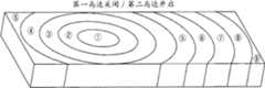
作为在这样的条件下模拟得到的振动力的实际测量结果,振动力的分布显示了在对角线方向上的对称形状,如图1B所示。图1A是当振动器20安装在长方体的便携式终端10的左上侧时便携式终端10的透视图。图1B示出图1A的便携式终端的振动力的分布。在此情况下,振动器20在z轴方向上振动。As an actual measurement result of the vibration force simulated under such conditions, the distribution of the vibration force showed a symmetrical shape in the diagonal direction, as shown in FIG. 1B . FIG. 1A is a perspective view of the
图1B示出了在振动器20如图1A所示布置在便携式终端10的左上侧的情况下,当振动器20产生175Hz频率的1N的力时由便携式终端10产生的振动位移。振动位移与振动力成比例。尽管振动位移根据刚体(也就是,便携式终端10)的重量、尺寸、材料、振动频率和产生的力而变化,但是位移的分布几乎与图1B相同。在图1B中,振动位移部分①示出小位移,振动位移部分⑨示出大位移。也就是,附图示出了位移朝着振动位移部分⑨而变大。图1B能够被理解为振动力在基于便携式终端的前表面的对角线方向上分布。因此,使用者难于察觉振动方向,也就是难于察觉振动从便携式终端的上侧、下侧、左侧和右侧中的哪个部分产生。FIG. 1B shows a vibration displacement generated by the
这是因为便携式终端的内部具有用于多种功能的紧凑结构,其外壳由具有高硬度的塑料或金属材料制成,振动以几km/s的速度很快地传播。因此,振动不是局部的。This is because the interior of the portable terminal has a compact structure for various functions, its housing is made of plastic or metal material with high hardness, and vibrations propagate quickly at a speed of several km/s. Therefore, the vibration is not localized.
图2示出了当线性振动器用作图1A的便携式终端10中的振动器20时在振动产生时在不同位置测量的振动力。测量位置UL、UR、DL和DR表示前表面30的上端和下端的位置,测量位置R1、R2、R3、L1、L2和L3表示前表面30的右侧和左侧的位置。对应于各个测量位置的振动波形从顶部依次表示x轴、y轴和z轴方向的振动力。振动器20的振动方向是z轴方向,也就是基于便携式终端10的显示屏的垂直方向。FIG. 2 shows vibration forces measured at different positions when vibration is generated when a linear vibrator is used as the
通常,当使用者握持便携式终端10时,使用者的手掌不接触便携式终端10的底表面,使用者的手指紧密接触便携式终端10的侧表面。如图2所示,由于振动力的分布趋于如图1B所示在对角线的方向上变化,所以便携式终端10在对角线方向的相对侧强烈地振动,而在对角线方向的中心附近微弱地振动。因此,使用者不能清楚地察觉振动产生的位置。Generally, when a user holds the
提供本发明以解决这些现有技术的问题,并且本发明通过控制多个振动器的驱动时间和强度来提供方向感和运动感。为此,多个振动器布置在便携式终端的内部,使得振动力的分布在一个方向上强而在另一方向上弱。运动感指的是由使用者感觉到的好像振动从便携式终端的特定部分连续移动到其它部分而不是在便携式终端的特定部分固定地产生。The present invention is provided to solve these problems of the prior art, and provides a sense of direction and a sense of movement by controlling the driving time and intensity of a plurality of vibrators. For this, a plurality of vibrators are arranged inside the portable terminal such that the distribution of vibration force is strong in one direction and weak in another direction. The sense of motion refers to a feeling felt by a user as if vibrations are continuously moved from a specific part of the portable terminal to other parts rather than being fixedly generated at a specific part of the portable terminal.
应用本发明的便携式终端的示例在图3中示出。便携式终端是指能够将其握持在一只手中而携带并能在使用者移动时进行输入操作的小尺寸终端器件。例如,便携式终端包括诸如手机的移动通信终端、PDA、便携式DMB终端、MP3播放器、PMP以及诸如PSP系统的便携式游戏机。An example of a portable terminal to which the present invention is applied is shown in FIG. 3 . A portable terminal refers to a small-sized terminal device that can be held in one hand and carried and can perform input operations when the user moves. Portable terminals include, for example, mobile communication terminals such as cell phones, PDAs, portable DMB terminals, MP3 players, PMPs, and portable game machines such as PSP systems.
图3示出了移动通信终端的示例,并包括马达作为振动器。尽管图3示出了移动通信终端,但是本发明的构造可以应用到其它类型的便携式终端。FIG. 3 shows an example of a mobile communication terminal, and includes a motor as a vibrator. Although FIG. 3 shows a mobile communication terminal, the configuration of the present invention can be applied to other types of portable terminals.
移动通信终端100包括存储器110、控制器120、移动通信部分130、多个马达140和150以及显示器160。The
控制器120控制移动通信终端100的整个操作。The
显示器160在控制器120的控制下将从移动通信基站接收或储存在存储器110中的视频信息、数据和图像显示在屏幕上。The
移动通信部分130在控制器120的控制下处理对于移动通信所需的操作和信号。移动通信部分130通过天线将无线信号发送到基站以及从基站接收无线信号。移动通信部分130通过基带处理器调制从控制器120输入的发送信号,并将调制的无线信号通过天线发送。移动通信部分130解调通过天线接收的无线信号,并通过基带处理器将解调的信号传输到控制器120。基带处理器处理被控制器120发送和接收的基带信号。The
第一马达140和第二马达150是线性马达(linear motor)。由于线性马达产生在一个轴的方向上的振动,所以它们的振动特性是简单的。由于线性马达的这种特性,如果线性马达安装为平行于基于便携式终端的前表面的垂直方向(即,z轴方向),则振动力如图1B所示分布在对角线方向上。The
因此,在本发明中,多个振动器安装在以预定距离彼此分离的位置上,使得由终端中的多个振动器产生的振动能够在基于便携式终端的前表面的左右方向(a left and right direction)或上下方向(an up and down direction)中的任一方向上相同;也就是,在x轴方向或y轴方向上。例如,第一马达140和第二马达150可以安装在移动通信终端100中,使得它们的振动方向在左右方向上(即,如图2所示的x轴方向)上相同。Therefore, in the present invention, a plurality of vibrators are installed at positions separated from each other by a predetermined distance, so that vibrations generated by the plurality of vibrators in the terminal can be generated in a left and right direction based on the front surface of the portable terminal. direction) or an up and down direction (an up and down direction); that is, in the x-axis direction or the y-axis direction. For example, the
此示例在图4A中显示,示出了根据本发明实施例第一马达140和第二马达150安装在使得振动在基于移动通信终端100的前表面170的左右方向(即x轴方向)上产生的位置的情况。在图4A中,第一马达140和第二马达150在移动通信终端100的平行表面上对角地定位。因此,第一马达140和第二马达150以预定距离彼此分离,并且它们的振动方向与x轴方向相同。This example is shown in FIG. 4A , which shows that the
图4B和图4C是示出当马达140和150如图4A所示安装时由马达140和150产生的振动位移的分布的图形。图4B示出了当仅第一马达140处于打开状态时的振动位移,图4C示出了当仅第二马达150处于打开状态时的振动位移。图4B和图4C中,振动位移部分⑨表示具有大位移的区域,振动位移部分①表示具有小位移的区域。4B and 4C are graphs showing the distribution of vibration displacements generated by the
参考图4B和图4C,能够理解的是,前表面170的上端和下端的任一方向具有强振动,而相反方向具有弱振动。因此,振动力均匀地分布在上下方向上。Referring to FIGS. 4B and 4C , it can be understood that either direction of the upper and lower ends of the
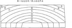
图5A是示出根据本发明另一实施例第一马达140和第二马达150安装在使得振动在基于移动通信终端100的前表面170的上下方向(即y轴方向)上产生的位置的情况。在图5A中,第一马达140和第二马达150位于移动通信终端100的同一表面上,但彼此分隔开预定距离。第一马达140和第二马达150的振动方向与y轴方向相同。FIG. 5A is a diagram illustrating a situation where the
图5B和图5C是示出当马达140和150如图5A所示安装时由马达140和150产生的振动位移的分布的图形。图5B示出当仅第一马达140被驱动时的振动位移,图5C示出当仅第二马达150被驱动时的振动位移。在图5B和图5C中,振动位移部分⑨表示具有大位移的区域,振动位移部分①表示具有小位移的区域。5B and 5C are graphs showing the distribution of vibration displacements generated by the
参照图5B和图5C,能够理解的是,前表面170的左侧和右侧的任一方向具有强振动,而相反方向具有弱振动。因此,振动力在左右方向上均匀分布。Referring to FIGS. 5B and 5C , it can be understood that either direction of the left and right sides of the
换句话说,如果安装线性马达140和150使得振动如常规方法地在前表面170的垂直方向(即z轴方向)上产生,那么振动力的分布在基于前表面170的对角线方向上变弱并在相反方向上变强,使用者不能感觉到方向感。然而,如果安装线性马达140和150使得振动在关于前表面170的水平方向上产生,那么振动的分布在一个方向上强而在另一方向上弱,能够获得左右方向感或者上下方向感。In other words, if the
这种方法不仅可以应用于线性马达还可以应用于能够在单一方向产生振动的所有振动器。即,如果振动器构造为使得振动在关于前表面170的水平方向上产生,则振动器可以与上述示例相同地操作。This approach can be applied not only to linear motors but to all vibrators capable of generating vibration in a single direction. That is, if the vibrator is configured such that vibration is generated in a horizontal direction with respect to the
由模拟结果能够理解的是,如果具有与长度相比相对小的宽度的刚体振动,则最大的振动力在振动产生在短轴方向上(关于宽度的水平方向上)时产生。因此,如果振动在短轴方向上产生,则能够以低功耗实现方向感。It can be understood from the simulation results that if a rigid body having a relatively small width compared to the length vibrates, the maximum vibration force is generated when the vibration is generated in the minor axis direction (horizontal direction with respect to the width). Therefore, if the vibration is generated in the short-axis direction, a sense of direction can be realized with low power consumption.
图6A和图6B是示出当第一马达140和第二马达150安装为实现上下方向感时振动力分布的实际测量数据的图形。在图6A和图6B所示的移动通信终端100中,第一马达140和第二马达150分别安装在基于前表面170的右上侧和右下侧,振动在基于前表面170的左右方向上(即x轴方向上)产生。FIGS. 6A and 6B are graphs showing actual measurement data of vibration force distribution when the
图6A示出当仅第一马达140在175Hz频率和3周期输入(3-cycle input)驱动时振动力分布的实际测量数据(电压:6Vpp,单位:m/s2)。图6B示出当仅第二马达150在320Hz频率和5周期输入驱动时振动力分布的实际测量数据。FIG. 6A shows actual measurement data (voltage: 6 Vpp, unit: m/s2 ) of the vibration force distribution when only the
图6A和图6B中的各个数字表示移动通信终端100与图2的便携式终端的位置UL、UR、L1、L2、L3、R1、R2、R3、DL和DR相对应的各个位置的总加速度。总加速度由三个轴的加速度的平方和的开方计算得到。与每个总加速度相对应的三个波形图样依次表示当实际由正弦波驱动时y轴、z轴和x轴的振动图样。总加速度与振动力成正比。参照图6A和图6B,随着振动在左右方向(即x轴方向)上产生,在上端和下端的振动力之间的差值不变地保持在约3dB,使用者能够识别振动在上端。如果振动器布置在上端和下端并被驱动,能够实现方向感或运动感。Each number in FIGS. 6A and 6B represents the total acceleration of each position of the
如果振动器以此方式布置,则振动在一个方向强而在另一方向弱,从而在振动发生时使用者能够感受到左右方向感或者上下方向感。换句话说,在本发明中,能够表示振动在上侧、下侧、左侧和右侧中的哪一侧产生。如果多个振动器在具有时间差的不同时间点被驱动,甚至能够实现左右运动感或者上下运动感。如果控制各个振动器的强度和驱动时间,则能够实现各种运动感,诸如连续移动的感觉或者步进移动的感觉。If the vibrator is arranged in this way, the vibration is strong in one direction and weak in the other direction, so that the user can feel a left-right direction sense or an up-and-down direction sense when the vibration occurs. In other words, in the present invention, it can be indicated on which side the vibration is generated among the upper side, the lower side, the left side, and the right side. If a plurality of vibrators are driven at different time points with a time difference, it is even possible to realize a left-right motion sense or an up-and-down motion sense. If the strength and driving time of each vibrator are controlled, various motion sensations such as a sense of continuous movement or a sense of step movement can be realized.
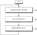
为了实现运动感,控制器120在图7的步骤201中根据终端的控制来确定振动的移动方向和强度。在步骤203中,控制器120根据振动的移动方向和强度来确定各个马达的振动图样。控制器120根据确定的振动图样来驱动马达140和150。In order to realize the sense of movement, the
实现运动感的示例在图8A和图8B中示出。图8A示出当第一马达140和第二马达150安装为使得能够实现上下方向感时的另一示例。第一马达140和第二马达150安装在基于移动通信终端100的前表面170的右上侧和右下侧,振动在基于前表面170的左右方向(即,x轴方向)上产生。An example of realizing a sense of motion is shown in FIGS. 8A and 8B . FIG. 8A shows another example when the
在如上所述构造的移动通信终端100中,如果控制器120根据图8B示出的振动图样315、325、335、345和355来驱动第一马达140和第二马达150,在移动通信终端100中在相应于各个移动图样315、325、335、345和355的移动方向310、320、330、340和350上实现由于振动产生的运动感。In the
控制器120首先根据第一振动图样315驱动第一马达140,并控制振动强度使得强度逐渐变弱。控制器120在振动的强度变弱的时间点上驱动第二马达150,并控制第二马达150的振动强度使得强度逐渐变强。在第一移动方向310上,强振动首先产生在移动通信终端100的上端,强振动接着产生在移动通信终端100的下端。因此,能够实现好像振动从上端移动到下端一样的运动感。The
接着,如果控制器120以与上述示例相反的方法接连驱动第一马达140和第二马达150,也就是如果控制器120根据第三振动图样335驱动马达140和150,能够实现类似于第三移动方向330的运动感,好像振动从上端移动到下端,再从下端移动到上端一样。也就是,由于振动产生的位置根据时间而依次变为上端、下端和上端,所以使用者感觉像是振动从上端移动到下端,再从下端移动到上端一样。在此情况下,一个马达的振动强度逐渐减小,而另一马达的振动强度逐渐增大。Then, if the
作为另一示例,控制器120首先根据第二振动图样325驱动第二马达150并偶尔停止驱动第二马达150同时控制第二马达150的振动强度使得强度逐渐变弱。如果控制器120通过在第二马达150的振动强度变弱的时间点上驱动第一马达140来控制第一马达140的振动强度使得强度逐渐变强并偶然停止驱动第一马达140,能够实现类似于第二移动方向320的运动感,好像强振动首先在移动通信终端100的下端产生然后该振动步进地移动一样。As another example, the
接着,如果控制器120以与上述示例相反的方法接连驱动第一马达140和第二马达150,也就是如果控制器120根据第四振动图样345驱动马达140和150时,能够实现类似于第四移动方向340的运动感,好像振动从下端步进地移动到上端,再从上端步进地移动到下端一样。Then, if the
如果控制器120根据第五振动图样355交替驱动第一马达140和第二马达150,能够实现类似于第五移动方向350的方向感,好像振动交替产生在移动通信终端100的上端和下端一样。If the
根据本发明,通过适当地布置两个振动器并控制振动的发生,使用者能够感受到振动的方向感和运动感。According to the present invention, by properly arranging the two vibrators and controlling the occurrence of vibration, the user can feel the sense of direction and motion of the vibration.
尽管为了说明的目的而描述了本发明的示范性实施例,但是可以有各种修改、添加和替换,而不脱离本发明的由权利要求书所公开的精神和范围。例如,除了移动通信终端100之外,上述实施例可以类似地应用于其它类型的便携式终端。可以使用压电马达或电致动马达(electroactive motor)来代替线性马达作为振动器。多个马达的频率可以相同或不同,多个振动器的共振频率可以不同。在相对高频(250至500Hz)下驱动的线性振动器可以用于使使用者识别硬感、粗糙感和节奏感。因此,本发明的范围不应限于以上实施例的描述,而是由权利要求书及其等同物限定。Although the exemplary embodiments of the present invention have been described for illustrative purposes, various modifications, additions and substitutions are possible without departing from the spirit and scope of the present invention as disclosed by the claims. For example, in addition to the
Claims (15)
Applications Claiming Priority (2)
| Application Number | Priority Date | Filing Date | Title |
|---|---|---|---|
| KR20090063221AKR20110005587A (en) | 2009-07-10 | 2009-07-10 | Method and apparatus for generating vibration of a mobile terminal |
| KR63221/09 | 2009-07-10 |
Publications (2)
| Publication Number | Publication Date |
|---|---|
| CN101947508Atrue CN101947508A (en) | 2011-01-19 |
| CN101947508B CN101947508B (en) | 2015-04-01 |
Family
ID=42668360
Family Applications (1)
| Application Number | Title | Priority Date | Filing Date |
|---|---|---|---|
| CN201010227577.8AExpired - Fee RelatedCN101947508B (en) | 2009-07-10 | 2010-07-12 | Method and apparatus for generating vibration in portable terminal |
Country Status (4)
| Country | Link |
|---|---|
| US (1) | US9120009B2 (en) |
| EP (2) | EP2278431A3 (en) |
| KR (1) | KR20110005587A (en) |
| CN (1) | CN101947508B (en) |
Cited By (11)
| Publication number | Priority date | Publication date | Assignee | Title |
|---|---|---|---|---|
| CN103856616A (en)* | 2012-12-03 | 2014-06-11 | 联想(北京)有限公司 | Method for generating prompt information and electronic device |
| CN104034971A (en)* | 2013-03-04 | 2014-09-10 | 联想(北京)有限公司 | Method and apparatus for charging detection of electronic device |
| CN105511628A (en)* | 2015-12-25 | 2016-04-20 | 魅族科技(中国)有限公司 | Method for controlling motor and terminal |
| CN105635491A (en)* | 2016-03-25 | 2016-06-01 | 广东欧珀移动通信有限公司 | Vibration adjustment method, system and electronic device |
| CN106774853A (en)* | 2016-11-28 | 2017-05-31 | 珠海市魅族科技有限公司 | A kind of seismaesthesia feedback method and terminal |
| CN106873781A (en)* | 2017-03-22 | 2017-06-20 | 信利光电股份有限公司 | A kind of electronic equipment |
| CN109675304A (en)* | 2017-10-19 | 2019-04-26 | 深圳市东上力达科技有限公司 | Mobile phone games synchronous vibrating device |
| CN109901703A (en)* | 2017-12-11 | 2019-06-18 | 北京小米移动软件有限公司 | A terminal, a vibration method for the terminal, and a storage medium |
| CN110121008A (en)* | 2019-05-21 | 2019-08-13 | Oppo广东移动通信有限公司 | vibration method, terminal and storage medium |
| CN110292771A (en)* | 2019-07-04 | 2019-10-01 | 网易(杭州)网络有限公司 | Haptic feedback control method and device, equipment, medium in game |
| CN111371956A (en)* | 2020-05-20 | 2020-07-03 | 北京小米移动软件有限公司 | A method and device for reducing displacement when a mobile phone vibrates |
Families Citing this family (53)
| Publication number | Priority date | Publication date | Assignee | Title |
|---|---|---|---|---|
| KR20110074333A (en)* | 2009-12-24 | 2011-06-30 | 삼성전자주식회사 | Method and apparatus for generating vibration of a mobile terminal |
| JP5887830B2 (en)* | 2010-12-10 | 2016-03-16 | 株式会社ニコン | Electronic device and vibration method |
| US9652944B2 (en)* | 2010-12-28 | 2017-05-16 | Lg Innotek Co., Ltd | Locally vibrating haptic apparatus, method for locally vibrating haptic apparatus, haptic display apparatus and vibrating panel using the same |
| US20120188065A1 (en)* | 2011-01-25 | 2012-07-26 | Harris Corporation | Methods and systems for indicating device status |
| KR101950017B1 (en)* | 2011-05-13 | 2019-02-19 | 엘지이노텍 주식회사 | Actuator for camera module and mobile device using the same |
| US10180722B2 (en)* | 2011-05-27 | 2019-01-15 | Honeywell International Inc. | Aircraft user interfaces with multi-mode haptics |
| KR200457799Y1 (en)* | 2011-09-05 | 2012-01-03 | 임종우 | Food packaging box with integrated finger cap |
| WO2013170099A1 (en)* | 2012-05-09 | 2013-11-14 | Yknots Industries Llc | Calibration of haptic feedback systems for input devices |
| WO2013188307A2 (en) | 2012-06-12 | 2013-12-19 | Yknots Industries Llc | Haptic electromagnetic actuator |
| US20140222437A1 (en)* | 2013-02-01 | 2014-08-07 | Plantronics, Inc. | Out-of-Band Notification of Muting During Voice Activity |
| GB2513884B (en) | 2013-05-08 | 2015-06-17 | Univ Bristol | Method and apparatus for producing an acoustic field |
| US9164587B2 (en) | 2013-11-14 | 2015-10-20 | Immersion Corporation | Haptic spatialization system |
| US9619029B2 (en) | 2013-11-14 | 2017-04-11 | Immersion Corporation | Haptic trigger control system |
| US9612658B2 (en) | 2014-01-07 | 2017-04-04 | Ultrahaptics Ip Ltd | Method and apparatus for providing tactile sensations |
| US20150242037A1 (en) | 2014-01-13 | 2015-08-27 | Apple Inc. | Transparent force sensor with strain relief |
| US20150301602A1 (en)* | 2014-04-16 | 2015-10-22 | International Business Machines Corporation | Multi Axis Vibration Unit In Device For Tactile Feedback |
| US9588586B2 (en)* | 2014-06-09 | 2017-03-07 | Immersion Corporation | Programmable haptic devices and methods for modifying haptic strength based on perspective and/or proximity |
| US10297119B1 (en) | 2014-09-02 | 2019-05-21 | Apple Inc. | Feedback device in an electronic device |
| GB2530036A (en) | 2014-09-09 | 2016-03-16 | Ultrahaptics Ltd | Method and apparatus for modulating haptic feedback |
| JP5956525B2 (en)* | 2014-10-01 | 2016-07-27 | レノボ・シンガポール・プライベート・リミテッド | Input device |
| US10185396B2 (en) | 2014-11-12 | 2019-01-22 | Immersion Corporation | Haptic trigger modification system |
| KR20160088081A (en)* | 2015-01-15 | 2016-07-25 | 삼성전자주식회사 | Haptic interface of image photographing device and method for controlling image photogrqphing device thereof |
| CN107534810B (en) | 2015-02-20 | 2019-12-20 | 超级触觉资讯处理有限公司 | Method for providing improved haptic feedback |
| CA2976312C (en) | 2015-02-20 | 2023-06-13 | Ultrahaptics Ip Limited | Perceptions in a haptic system |
| US9798409B1 (en) | 2015-03-04 | 2017-10-24 | Apple Inc. | Multi-force input device |
| WO2016148182A1 (en)* | 2015-03-18 | 2016-09-22 | 株式会社ニコン | Electronic device and program |
| US10818162B2 (en) | 2015-07-16 | 2020-10-27 | Ultrahaptics Ip Ltd | Calibration techniques in haptic systems |
| CN105204542B (en)* | 2015-09-11 | 2018-02-02 | 小米科技有限责任公司 | The vibration control method and device of motor |
| CN105227003A (en)* | 2015-10-08 | 2016-01-06 | 瑞声光电科技(常州)有限公司 | Many electric machine frequencies control system and control method thereof |
| US11189140B2 (en) | 2016-01-05 | 2021-11-30 | Ultrahaptics Ip Ltd | Calibration and detection techniques in haptic systems |
| US10268275B2 (en) | 2016-08-03 | 2019-04-23 | Ultrahaptics Ip Ltd | Three-dimensional perceptions in haptic systems |
| US10943578B2 (en) | 2016-12-13 | 2021-03-09 | Ultrahaptics Ip Ltd | Driving techniques for phased-array systems |
| CN109279463B (en) | 2017-07-19 | 2021-06-08 | 奥的斯电梯公司 | Intelligent guidance for controlling passengers to enter correct elevator cars |
| KR102518400B1 (en) | 2017-11-22 | 2023-04-06 | 삼성전자주식회사 | Method for providing vibration and electronic device for supporting the same |
| US11531395B2 (en)* | 2017-11-26 | 2022-12-20 | Ultrahaptics Ip Ltd | Haptic effects from focused acoustic fields |
| EP3729418B1 (en) | 2017-12-22 | 2024-11-20 | Ultrahaptics Ip Ltd | Minimizing unwanted responses in haptic systems |
| EP3729417B1 (en) | 2017-12-22 | 2025-09-10 | Ultrahaptics Ip Ltd | Tracking in haptic systems |
| CA3098642C (en) | 2018-05-02 | 2022-04-19 | Ultrahaptics Ip Ltd | Blocking plate structure for improved acoustic transmission efficiency |
| US11098951B2 (en) | 2018-09-09 | 2021-08-24 | Ultrahaptics Ip Ltd | Ultrasonic-assisted liquid manipulation |
| US11378997B2 (en) | 2018-10-12 | 2022-07-05 | Ultrahaptics Ip Ltd | Variable phase and frequency pulse-width modulation technique |
| US12373033B2 (en) | 2019-01-04 | 2025-07-29 | Ultrahaptics Ip Ltd | Mid-air haptic textures |
| EP3906462B1 (en) | 2019-01-04 | 2025-06-18 | Ultrahaptics IP Ltd | Mid-air haptic textures |
| KR102099969B1 (en)* | 2019-02-13 | 2020-05-15 | 엘지이노텍 주식회사 | Mobile device |
| US10852833B2 (en)* | 2019-03-29 | 2020-12-01 | Google Llc | Global and local haptic system and mobile devices including the same |
| US11842517B2 (en) | 2019-04-12 | 2023-12-12 | Ultrahaptics Ip Ltd | Using iterative 3D-model fitting for domain adaptation of a hand-pose-estimation neural network |
| US11553295B2 (en) | 2019-10-13 | 2023-01-10 | Ultraleap Limited | Dynamic capping with virtual microphones |
| US11374586B2 (en) | 2019-10-13 | 2022-06-28 | Ultraleap Limited | Reducing harmonic distortion by dithering |
| US11169610B2 (en) | 2019-11-08 | 2021-11-09 | Ultraleap Limited | Tracking techniques in haptic systems |
| US11715453B2 (en) | 2019-12-25 | 2023-08-01 | Ultraleap Limited | Acoustic transducer structures |
| JP7373445B2 (en)* | 2020-03-27 | 2023-11-02 | ニデックプレシジョン株式会社 | Vibration actuator and its driving method |
| KR102439882B1 (en)* | 2020-04-06 | 2022-09-05 | 엘지이노텍 주식회사 | Mobile device |
| US11816267B2 (en) | 2020-06-23 | 2023-11-14 | Ultraleap Limited | Features of airborne ultrasonic fields |
| US11886639B2 (en) | 2020-09-17 | 2024-01-30 | Ultraleap Limited | Ultrahapticons |
Citations (4)
| Publication number | Priority date | Publication date | Assignee | Title |
|---|---|---|---|---|
| CN1392977A (en)* | 2000-08-08 | 2003-01-22 | 株式会社Ntt都科摩 | Electronic apparatus, vibration generator, vibratory informing method and method for controlling information |
| US20030038776A1 (en)* | 1998-06-23 | 2003-02-27 | Immersion Corporation | Haptic feedback for touchpads and other touch controls |
| CN1955903A (en)* | 2005-10-28 | 2007-05-02 | 索尼株式会社 | Electronic apparatus |
| US20090058829A1 (en)* | 2007-08-30 | 2009-03-05 | Young Hwan Kim | Apparatus and method for providing feedback for three-dimensional touchscreen |
Family Cites Families (13)
| Publication number | Priority date | Publication date | Assignee | Title |
|---|---|---|---|---|
| US6776717B2 (en) | 1997-08-24 | 2004-08-17 | Sony Computer Entertainment, Inc. | Game apparatus, game machine manipulation device, game system and interactive communication method for game apparatus |
| US6680729B1 (en)* | 1999-09-30 | 2004-01-20 | Immersion Corporation | Increasing force transmissibility for tactile feedback interface devices |
| US7182691B1 (en) | 2000-09-28 | 2007-02-27 | Immersion Corporation | Directional inertial tactile feedback using rotating masses |
| US6864877B2 (en) | 2000-09-28 | 2005-03-08 | Immersion Corporation | Directional tactile feedback for haptic feedback interface devices |
| TWI221068B (en)* | 2003-03-27 | 2004-09-11 | Benq Corp | Communication apparatus for demonstrating non-audio message by decoded vibrations |
| US7194099B2 (en) | 2003-06-10 | 2007-03-20 | Motorola, Inc. | Handheld electronics devices with multiple user sensory transducers and methods |
| JP2008182857A (en) | 2007-01-25 | 2008-08-07 | Kyocera Corp | Mobile terminal device |
| KR20080108651A (en) | 2007-06-11 | 2008-12-16 | 크루셜텍 (주) | Haptic Control Method by Cursor Movement |
| KR101425222B1 (en)* | 2007-08-22 | 2014-08-04 | 삼성전자주식회사 | Apparatus and method for vibration control in mobile phone |
| US20090088220A1 (en) | 2007-10-01 | 2009-04-02 | Sony Ericsson Mobile Communications Ab | Cellular terminals and other electronic devices and methods using electroactive polymer transducer indicators |
| US20090091479A1 (en)* | 2007-10-04 | 2009-04-09 | Motorola, Inc. | Keypad haptic communication |
| US8362896B2 (en)* | 2008-03-19 | 2013-01-29 | United Parcel Service Of America, Inc. | Methods and systems for alerting persons of obstacles or approaching hazards |
| KR101602500B1 (en)* | 2009-09-08 | 2016-03-10 | 엘지전자 주식회사 | Mobile Device and Method for Controlling Vibration thereof |
- 2009
- 2009-07-10KRKR20090063221Apatent/KR20110005587A/ennot_activeCeased
- 2010
- 2010-07-09USUS12/833,619patent/US9120009B2/ennot_activeExpired - Fee Related
- 2010-07-12CNCN201010227577.8Apatent/CN101947508B/ennot_activeExpired - Fee Related
- 2010-07-12EPEP20100169217patent/EP2278431A3/ennot_activeCeased
- 2010-07-12EPEP15164221.2Apatent/EP2933704A1/ennot_activeCeased
Patent Citations (4)
| Publication number | Priority date | Publication date | Assignee | Title |
|---|---|---|---|---|
| US20030038776A1 (en)* | 1998-06-23 | 2003-02-27 | Immersion Corporation | Haptic feedback for touchpads and other touch controls |
| CN1392977A (en)* | 2000-08-08 | 2003-01-22 | 株式会社Ntt都科摩 | Electronic apparatus, vibration generator, vibratory informing method and method for controlling information |
| CN1955903A (en)* | 2005-10-28 | 2007-05-02 | 索尼株式会社 | Electronic apparatus |
| US20090058829A1 (en)* | 2007-08-30 | 2009-03-05 | Young Hwan Kim | Apparatus and method for providing feedback for three-dimensional touchscreen |
Cited By (15)
| Publication number | Priority date | Publication date | Assignee | Title |
|---|---|---|---|---|
| CN103856616A (en)* | 2012-12-03 | 2014-06-11 | 联想(北京)有限公司 | Method for generating prompt information and electronic device |
| CN103856616B (en)* | 2012-12-03 | 2016-08-17 | 联想(北京)有限公司 | Method for generating prompt information and electronic device |
| CN106231069A (en)* | 2012-12-03 | 2016-12-14 | 联想(北京)有限公司 | A kind of information generates method and electronic equipment |
| CN104034971A (en)* | 2013-03-04 | 2014-09-10 | 联想(北京)有限公司 | Method and apparatus for charging detection of electronic device |
| CN105511628A (en)* | 2015-12-25 | 2016-04-20 | 魅族科技(中国)有限公司 | Method for controlling motor and terminal |
| CN105635491A (en)* | 2016-03-25 | 2016-06-01 | 广东欧珀移动通信有限公司 | Vibration adjustment method, system and electronic device |
| CN106774853A (en)* | 2016-11-28 | 2017-05-31 | 珠海市魅族科技有限公司 | A kind of seismaesthesia feedback method and terminal |
| CN106873781A (en)* | 2017-03-22 | 2017-06-20 | 信利光电股份有限公司 | A kind of electronic equipment |
| CN109675304A (en)* | 2017-10-19 | 2019-04-26 | 深圳市东上力达科技有限公司 | Mobile phone games synchronous vibrating device |
| CN109901703A (en)* | 2017-12-11 | 2019-06-18 | 北京小米移动软件有限公司 | A terminal, a vibration method for the terminal, and a storage medium |
| CN109901703B (en)* | 2017-12-11 | 2022-05-06 | 北京小米移动软件有限公司 | A terminal, a vibration method for the terminal, and a storage medium |
| CN110121008A (en)* | 2019-05-21 | 2019-08-13 | Oppo广东移动通信有限公司 | vibration method, terminal and storage medium |
| CN110292771A (en)* | 2019-07-04 | 2019-10-01 | 网易(杭州)网络有限公司 | Haptic feedback control method and device, equipment, medium in game |
| CN110292771B (en)* | 2019-07-04 | 2022-09-13 | 网易(杭州)网络有限公司 | Method, device, equipment and medium for controlling tactile feedback in game |
| CN111371956A (en)* | 2020-05-20 | 2020-07-03 | 北京小米移动软件有限公司 | A method and device for reducing displacement when a mobile phone vibrates |
Also Published As
| Publication number | Publication date |
|---|---|
| US20110006888A1 (en) | 2011-01-13 |
| CN101947508B (en) | 2015-04-01 |
| KR20110005587A (en) | 2011-01-18 |
| EP2278431A2 (en) | 2011-01-26 |
| US9120009B2 (en) | 2015-09-01 |
| EP2278431A3 (en) | 2012-09-19 |
| EP2933704A1 (en) | 2015-10-21 |
Similar Documents
| Publication | Publication Date | Title |
|---|---|---|
| CN101947508B (en) | Method and apparatus for generating vibration in portable terminal | |
| CN102111496B (en) | Method and apparatus for generating vibration in portable terminal | |
| US8912693B2 (en) | Broadband linear vibrator and mobile terminal | |
| KR101523796B1 (en) | Directional haptic effects for a handheld device | |
| JP6341417B2 (en) | Vibration generation system, vibration generation program, and vibration generation method | |
| US7656388B2 (en) | Controlling vibrotactile sensations for haptic feedback devices | |
| CN103181090B (en) | Vibration module for portable terminal | |
| WO2011099554A1 (en) | Electronic device | |
| EP3093736A1 (en) | Systems and methods for haptic feedback for modular devices | |
| US8259066B2 (en) | Impact force feedback device and interactive system using the same | |
| CN107797653A (en) | The generation method of tactile actuator, electronic equipment and touch feedback | |
| KR20150048685A (en) | Protective case for mobile terminalproviding real time vibration feedback | |
| CN204810110U (en) | Linear vibration motor | |
| CN104460983A (en) | Orientation adjustable multi-channel haptic device | |
| CN103218104A (en) | Electronic terminal and method for controlling vibration direction of electronic terminal | |
| JP2018206012A (en) | Information processing system, information processing program, information processor, and method for information processing | |
| CN110266856A (en) | Electronic equipment and vibration device, method | |
| WO2001003105A1 (en) | Controlling vibrotactile sensations for haptic feedback devices | |
| WO2001003105A9 (en) | Controlling vibrotactile sensations for haptic feedback devices | |
| CN103853363A (en) | Tactile feedback method and electronic device | |
| JP6837921B2 (en) | Game programs, information processing devices, information processing systems, and information processing methods | |
| KR20160039175A (en) | Method and apparatus for generating vibration in portable terminal | |
| KR20040103621A (en) | Terminal vibration apparatus and method |
Legal Events
| Date | Code | Title | Description |
|---|---|---|---|
| C06 | Publication | ||
| PB01 | Publication | ||
| C10 | Entry into substantive examination | ||
| SE01 | Entry into force of request for substantive examination | ||
| C14 | Grant of patent or utility model | ||
| GR01 | Patent grant | ||
| CF01 | Termination of patent right due to non-payment of annual fee | Granted publication date:20150401 Termination date:20190712 | |
| CF01 | Termination of patent right due to non-payment of annual fee |