CN101946337B - Molded resin product, semiconductor light emitting source, lighting device, and manufacturing method of molded resin product - Google Patents
Molded resin product, semiconductor light emitting source, lighting device, and manufacturing method of molded resin productDownload PDFInfo
- Publication number
- CN101946337B CN101946337BCN2009801054735ACN200980105473ACN101946337BCN 101946337 BCN101946337 BCN 101946337BCN 2009801054735 ACN2009801054735 ACN 2009801054735ACN 200980105473 ACN200980105473 ACN 200980105473ACN 101946337 BCN101946337 BCN 101946337B
- Authority
- CN
- China
- Prior art keywords
- shape
- resin
- resin product
- molded resin
- resin member
- Prior art date
- Legal status (The legal status is an assumption and is not a legal conclusion. Google has not performed a legal analysis and makes no representation as to the accuracy of the status listed.)
- Active
Links
Images


Classifications
- B—PERFORMING OPERATIONS; TRANSPORTING
- B29—WORKING OF PLASTICS; WORKING OF SUBSTANCES IN A PLASTIC STATE IN GENERAL
- B29C—SHAPING OR JOINING OF PLASTICS; SHAPING OF MATERIAL IN A PLASTIC STATE, NOT OTHERWISE PROVIDED FOR; AFTER-TREATMENT OF THE SHAPED PRODUCTS, e.g. REPAIRING
- B29C33/00—Moulds or cores; Details thereof or accessories therefor
- B29C33/0011—Moulds or cores; Details thereof or accessories therefor thin-walled moulds
- B29C33/0016—Lost moulds, e.g. staying on the moulded object
- F—MECHANICAL ENGINEERING; LIGHTING; HEATING; WEAPONS; BLASTING
- F21—LIGHTING
- F21K—NON-ELECTRIC LIGHT SOURCES USING LUMINESCENCE; LIGHT SOURCES USING ELECTROCHEMILUMINESCENCE; LIGHT SOURCES USING CHARGES OF COMBUSTIBLE MATERIAL; LIGHT SOURCES USING SEMICONDUCTOR DEVICES AS LIGHT-GENERATING ELEMENTS; LIGHT SOURCES NOT OTHERWISE PROVIDED FOR
- F21K9/00—Light sources using semiconductor devices as light-generating elements, e.g. using light-emitting diodes [LED] or lasers
- F21K9/20—Light sources comprising attachment means
- F21K9/23—Retrofit light sources for lighting devices with a single fitting for each light source, e.g. for substitution of incandescent lamps with bayonet or threaded fittings
- F21K9/232—Retrofit light sources for lighting devices with a single fitting for each light source, e.g. for substitution of incandescent lamps with bayonet or threaded fittings specially adapted for generating an essentially omnidirectional light distribution, e.g. with a glass bulb
- F—MECHANICAL ENGINEERING; LIGHTING; HEATING; WEAPONS; BLASTING
- F21—LIGHTING
- F21K—NON-ELECTRIC LIGHT SOURCES USING LUMINESCENCE; LIGHT SOURCES USING ELECTROCHEMILUMINESCENCE; LIGHT SOURCES USING CHARGES OF COMBUSTIBLE MATERIAL; LIGHT SOURCES USING SEMICONDUCTOR DEVICES AS LIGHT-GENERATING ELEMENTS; LIGHT SOURCES NOT OTHERWISE PROVIDED FOR
- F21K9/00—Light sources using semiconductor devices as light-generating elements, e.g. using light-emitting diodes [LED] or lasers
- F21K9/60—Optical arrangements integrated in the light source, e.g. for improving the colour rendering index or the light extraction
- F21K9/64—Optical arrangements integrated in the light source, e.g. for improving the colour rendering index or the light extraction using wavelength conversion means distinct or spaced from the light-generating element, e.g. a remote phosphor layer
- F—MECHANICAL ENGINEERING; LIGHTING; HEATING; WEAPONS; BLASTING
- F21—LIGHTING
- F21V—FUNCTIONAL FEATURES OR DETAILS OF LIGHTING DEVICES OR SYSTEMS THEREOF; STRUCTURAL COMBINATIONS OF LIGHTING DEVICES WITH OTHER ARTICLES, NOT OTHERWISE PROVIDED FOR
- F21V3/00—Globes; Bowls; Cover glasses
- F21V3/02—Globes; Bowls; Cover glasses characterised by the shape
- F—MECHANICAL ENGINEERING; LIGHTING; HEATING; WEAPONS; BLASTING
- F21—LIGHTING
- F21V—FUNCTIONAL FEATURES OR DETAILS OF LIGHTING DEVICES OR SYSTEMS THEREOF; STRUCTURAL COMBINATIONS OF LIGHTING DEVICES WITH OTHER ARTICLES, NOT OTHERWISE PROVIDED FOR
- F21V3/00—Globes; Bowls; Cover glasses
- F21V3/04—Globes; Bowls; Cover glasses characterised by materials, surface treatments or coatings
- F21V3/10—Globes; Bowls; Cover glasses characterised by materials, surface treatments or coatings characterised by coatings
- F21V3/12—Globes; Bowls; Cover glasses characterised by materials, surface treatments or coatings characterised by coatings the coatings comprising photoluminescent substances
- F—MECHANICAL ENGINEERING; LIGHTING; HEATING; WEAPONS; BLASTING
- F21—LIGHTING
- F21V—FUNCTIONAL FEATURES OR DETAILS OF LIGHTING DEVICES OR SYSTEMS THEREOF; STRUCTURAL COMBINATIONS OF LIGHTING DEVICES WITH OTHER ARTICLES, NOT OTHERWISE PROVIDED FOR
- F21V17/00—Fastening of component parts of lighting devices, e.g. shades, globes, refractors, reflectors, filters, screens, grids or protective cages
- F21V17/10—Fastening of component parts of lighting devices, e.g. shades, globes, refractors, reflectors, filters, screens, grids or protective cages characterised by specific fastening means or way of fastening
- F—MECHANICAL ENGINEERING; LIGHTING; HEATING; WEAPONS; BLASTING
- F21—LIGHTING
- F21Y—INDEXING SCHEME ASSOCIATED WITH SUBCLASSES F21K, F21L, F21S and F21V, RELATING TO THE FORM OR THE KIND OF THE LIGHT SOURCES OR OF THE COLOUR OF THE LIGHT EMITTED
- F21Y2115/00—Light-generating elements of semiconductor light sources
- F21Y2115/10—Light-emitting diodes [LED]
- H—ELECTRICITY
- H01—ELECTRIC ELEMENTS
- H01L—SEMICONDUCTOR DEVICES NOT COVERED BY CLASS H10
- H01L2224/00—Indexing scheme for arrangements for connecting or disconnecting semiconductor or solid-state bodies and methods related thereto as covered by H01L24/00
- H01L2224/01—Means for bonding being attached to, or being formed on, the surface to be connected, e.g. chip-to-package, die-attach, "first-level" interconnects; Manufacturing methods related thereto
- H01L2224/42—Wire connectors; Manufacturing methods related thereto
- H01L2224/44—Structure, shape, material or disposition of the wire connectors prior to the connecting process
- H01L2224/45—Structure, shape, material or disposition of the wire connectors prior to the connecting process of an individual wire connector
- H01L2224/45001—Core members of the connector
- H01L2224/45099—Material
- H01L2224/451—Material with a principal constituent of the material being a metal or a metalloid, e.g. boron (B), silicon (Si), germanium (Ge), arsenic (As), antimony (Sb), tellurium (Te) and polonium (Po), and alloys thereof
- H01L2224/45138—Material with a principal constituent of the material being a metal or a metalloid, e.g. boron (B), silicon (Si), germanium (Ge), arsenic (As), antimony (Sb), tellurium (Te) and polonium (Po), and alloys thereof the principal constituent melting at a temperature of greater than or equal to 950°C and less than 1550°C
- H01L2224/45144—Gold (Au) as principal constituent
- H—ELECTRICITY
- H01—ELECTRIC ELEMENTS
- H01L—SEMICONDUCTOR DEVICES NOT COVERED BY CLASS H10
- H01L2224/00—Indexing scheme for arrangements for connecting or disconnecting semiconductor or solid-state bodies and methods related thereto as covered by H01L24/00
- H01L2224/01—Means for bonding being attached to, or being formed on, the surface to be connected, e.g. chip-to-package, die-attach, "first-level" interconnects; Manufacturing methods related thereto
- H01L2224/42—Wire connectors; Manufacturing methods related thereto
- H01L2224/47—Structure, shape, material or disposition of the wire connectors after the connecting process
- H01L2224/48—Structure, shape, material or disposition of the wire connectors after the connecting process of an individual wire connector
- H01L2224/4805—Shape
- H01L2224/4809—Loop shape
- H01L2224/48091—Arched
- H—ELECTRICITY
- H01—ELECTRIC ELEMENTS
- H01L—SEMICONDUCTOR DEVICES NOT COVERED BY CLASS H10
- H01L25/00—Assemblies consisting of a plurality of semiconductor or other solid state devices
- H01L25/03—Assemblies consisting of a plurality of semiconductor or other solid state devices all the devices being of a type provided for in a single subclass of subclasses H10B, H10D, H10F, H10H, H10K or H10N, e.g. assemblies of rectifier diodes
- H01L25/04—Assemblies consisting of a plurality of semiconductor or other solid state devices all the devices being of a type provided for in a single subclass of subclasses H10B, H10D, H10F, H10H, H10K or H10N, e.g. assemblies of rectifier diodes the devices not having separate containers
- H01L25/075—Assemblies consisting of a plurality of semiconductor or other solid state devices all the devices being of a type provided for in a single subclass of subclasses H10B, H10D, H10F, H10H, H10K or H10N, e.g. assemblies of rectifier diodes the devices not having separate containers the devices being of a type provided for in group H10H20/00
- H01L25/0753—Assemblies consisting of a plurality of semiconductor or other solid state devices all the devices being of a type provided for in a single subclass of subclasses H10B, H10D, H10F, H10H, H10K or H10N, e.g. assemblies of rectifier diodes the devices not having separate containers the devices being of a type provided for in group H10H20/00 the devices being arranged next to each other
- H—ELECTRICITY
- H01—ELECTRIC ELEMENTS
- H01L—SEMICONDUCTOR DEVICES NOT COVERED BY CLASS H10
- H01L2924/00—Indexing scheme for arrangements or methods for connecting or disconnecting semiconductor or solid-state bodies as covered by H01L24/00
- H01L2924/15—Details of package parts other than the semiconductor or other solid state devices to be connected
- H01L2924/181—Encapsulation
- H—ELECTRICITY
- H10—SEMICONDUCTOR DEVICES; ELECTRIC SOLID-STATE DEVICES NOT OTHERWISE PROVIDED FOR
- H10H—INORGANIC LIGHT-EMITTING SEMICONDUCTOR DEVICES HAVING POTENTIAL BARRIERS
- H10H20/00—Individual inorganic light-emitting semiconductor devices having potential barriers, e.g. light-emitting diodes [LED]
- H10H20/80—Constructional details
- H10H20/85—Packages
- H10H20/851—Wavelength conversion means
- H10H20/8511—Wavelength conversion means characterised by their material, e.g. binder
- H—ELECTRICITY
- H10—SEMICONDUCTOR DEVICES; ELECTRIC SOLID-STATE DEVICES NOT OTHERWISE PROVIDED FOR
- H10H—INORGANIC LIGHT-EMITTING SEMICONDUCTOR DEVICES HAVING POTENTIAL BARRIERS
- H10H20/00—Individual inorganic light-emitting semiconductor devices having potential barriers, e.g. light-emitting diodes [LED]
- H10H20/80—Constructional details
- H10H20/85—Packages
- H10H20/855—Optical field-shaping means, e.g. lenses
Landscapes
- Engineering & Computer Science (AREA)
- General Engineering & Computer Science (AREA)
- Physics & Mathematics (AREA)
- Microelectronics & Electronic Packaging (AREA)
- Optics & Photonics (AREA)
- Mechanical Engineering (AREA)
- Led Device Packages (AREA)
- Casting Or Compression Moulding Of Plastics Or The Like (AREA)
- Non-Portable Lighting Devices Or Systems Thereof (AREA)
- Injection Moulding Of Plastics Or The Like (AREA)
Abstract
Translated fromChinese
Description
Translated fromChinese技术领域technical field
本发明涉及包含用于将由作为光源的半导体发光元件发射的光转换成期望颜色的荧光物质材料的模制树脂产品,用于制造该模制树脂产品的方法,以及使用该模制树脂产品的半导体发光源和照明装置。The present invention relates to a molded resin product containing a fluorescent substance material for converting light emitted by a semiconductor light emitting element as a light source into a desired color, a method for manufacturing the molded resin product, and a semiconductor using the molded resin product Lighting sources and lighting fixtures.
背景技术Background technique
近年来,由于例如LED元件的半导体发光元件的光发射效率已经改善,它们在照明用光源等中的应用已经迅速地发展。In recent years, since the light emission efficiency of semiconductor light emitting elements such as LED elements has been improved, their application to light sources for illumination and the like has been rapidly developed.
图13至15示出其中使用了LED元件的发光源的一个实例。13 to 15 show an example of a light emitting source in which LED elements are used.
如图13中所示,发光源101设有LED元件105,该LED元件作为光源实施在衬底103的主表面上。在LED元件105布置在反射板107的反射孔内的状态下,LED元件105用包含荧光物质材料的树脂来密封。注意,用于密封LED元件105的树脂称为密封树脂构件109。构成反射面107a的圆周表面反射来自LED元件105的光,使得所述光沿预定方向行进(见下文给出的专利文献1)。As shown in FIG. 13 , the
利用上述结构,当从LED元件105发射的光通过密封树脂构件109时,所述光由密封树脂构件109中包含的荧光物质材料转换成期望颜色,随后被直接从发光源101发射,或者被反射面107a反射以沿预定方向行进且随后从发光源101发射。With the above structure, when the light emitted from the
传统上使用环氧树脂、烯烃树脂等作为设于发光源101内的密封树脂构件109的材料。然而,这些树脂存在一个问题,即当这种树脂长时间使用时,由于例如当LED元件105发光时所产生的热,密封树脂构件109的颜色改变,从而导致从发光源101发射的光的数量减少。Conventionally, epoxy resin, olefin resin, or the like is used as a material of the sealing
近年来解决上述问题的典型趋势是,如图14或者15中所示,不包含荧光物质材料的树脂被用作密封LED元件105的树脂(此树脂也是密封树脂构件且由参考数字113和123表示),以及包含荧光物质材料的树脂(此树脂称为荧光物质层且由参考数字115和125表示)也被独立于密封树脂构件113和123而使用,其中诸如硅树脂的凝胶状或者橡胶状树脂被用作荧光物质层115和125(见下文给出的专利文献2)。A typical trend in recent years to solve the above-mentioned problems is that, as shown in FIG. ), and a resin containing a fluorescent substance material (this resin is called a fluorescent substance layer and is indicated by
这里还应注意,荧光物质层115和125可以如图14和15中所示分别制成具有基本上不变厚度的板的形状以及制成圆顶的形状,使得在通过密封树脂构件113或者123之后通过荧光物质层的光的光路径长度(其实例为图14中示出的L3和L4)可以相同,防止出现颜色不均匀。It should also be noted here that the
专利引用1:日本专利申请公开No.2005-311170Patent Citation 1: Japanese Patent Application Publication No. 2005-311170
专利引用2:日本专利申请公开No.2005-166733Patent Citation 2: Japanese Patent Application Publication No. 2005-166733
发明内容Contents of the invention
本发明解决的问题Problems solved by the present invention
然而,这种结构也存在问题。也就是说,当图14和15中示出的荧光物质层115和125是由凝胶状或者橡胶状树脂制成时,荧光物质层115和125形状随时间变化,导致外观的劣化、颜色不匀的扩展等等。However, there are also problems with this structure. That is, when the
为了防止发生此问题,在图14和15中示出的发光源111和121中,密封树脂构件113和123分别填充在LED元件105与荧光物质层115和125之间的空间内。In order to prevent this problem, in
因此本发明的目的是提供一种模制树脂产品、半导体发光源、照明装置以及用于制造该模制树脂产品的方法,该模制树脂产品设有由凝胶状或者橡胶状树脂制成的荧光物质层,而不使用图14和15所示的密封树脂构件,并且可以容易地实施,所述荧光物质层可以长时间保持其形状。It is therefore an object of the present invention to provide a molded resin product, a semiconductor light emitting source, a lighting device and a method for manufacturing the molded resin product provided with a gel-like or rubber-like resin. A fluorescent substance layer, which can maintain its shape for a long time, can be easily implemented without using the sealing resin member shown in FIGS. 14 and 15 .
解决问题的手段means of solving problems
上述目的是通过一种模制树脂产品来达成,该模制树脂产品包含:树脂构件,其由包含荧光物质材料的半透明树脂制成;以及形状保持构件,其由弹性模量高于树脂构件的材料制成,且其设于该树脂构件的内部或者设于该树脂构件的外表面上以保持该树脂构件的形状。The above objects are achieved by a molded resin product comprising: a resin member made of a translucent resin containing a fluorescent substance material; and a shape retaining member made of material, and it is provided inside the resin member or provided on the outer surface of the resin member to maintain the shape of the resin member.
发明效果Invention effect
本发明的模制树脂产品包含位于树脂构件的内部或者位于树脂构件的外表面上的形状保持构件。利用这种结构,树脂构件的形状自动地被长时间地保持住。The molded resin product of the present invention includes a shape retaining member inside the resin member or on the outer surface of the resin member. With this structure, the shape of the resin member is automatically maintained for a long time.
在上述模制树脂产品中,树脂构件可具有凸状部或者凹状部。另外,在用于作为光源的半导体发光元件中的上述模制树脂产品中,树脂构件可具有内部是中空的凸状部,且该凸状部沿纵断面呈圆弧状,且圆弧的半径设置为使得光发射的中心位于圆弧的中心(center of the circular arc)处和位于圆弧中心(circular arc center)附近。In the molded resin product described above, the resin member may have a convex portion or a concave portion. In addition, in the above-mentioned molded resin product used in semiconductor light-emitting elements as light sources, the resin member may have a hollow convex portion inside, and the convex portion has an arc shape along a longitudinal section, and the radius of the arc is Set so that the center of the light emission is at and near the center of the circular arc.
注意,沿纵断面的形状是指在沿与该凸状部凸出的方向垂直的平面截取的断面内的形状。Note that the shape along the longitudinal section means the shape in a section taken along a plane perpendicular to the direction in which the convex-shaped portion protrudes.
在上述模制树脂产品中,形状保持构件可由一个或多个线状构件构成。此外,在上述模制树脂产品中,形状保持构件在平面图内可以是螺旋形状、格子形状、平行线形状和放射线形状中的一种,或者是螺旋形状、格子形状、平行线形状和放射线形状中两种或更多种的组合的形状。In the above molded resin product, the shape maintaining member may be constituted by one or more linear members. Further, in the above-mentioned molded resin product, the shape retaining member may be one of a spiral shape, a lattice shape, a parallel line shape, and a radial shape in plan view, or one of a spiral shape, a lattice shape, a parallel line shape, and a radial shape. A combination of two or more shapes.
注意,在平面图内的形状是指在沿形状保持构件具有最大面积的方向观看时形状保持构件的形状。Note that the shape in plan view means the shape of the shape maintaining member when viewed in the direction in which the shape maintaining member has the largest area.
在上述模制树脂产品中,线状构件可沿线状构件的纵向方向缠绕成线圈形状。此外,在上述模制树脂产品中,树脂构件可具有凝胶状或者橡胶状弹性。另外,在上述模制树脂产品中,树脂构件可具有A80或更小的肖氏硬度。In the molded resin product described above, the wire-like member may be wound in a coil shape along the longitudinal direction of the wire-like member. Furthermore, in the molded resin product described above, the resin member may have gel-like or rubber-like elasticity. In addition, in the above molded resin product, the resin member may have a Shore hardness of A80 or less.
在上述模制树脂产品中,半透明树脂可包含硅树脂和氟树脂中的至少一种。此外,在上述模制树脂产品中,树脂构件可在其内部或者其外表面中包含颜料和光漫射材料中的至少一种。另外,在上述模制树脂产品中,凸状部可在其内部含有光漫射材料,并且在其外部含有荧光物质材料。In the above molded resin product, the translucent resin may contain at least one of silicone resin and fluororesin. Furthermore, in the molded resin product described above, the resin member may contain at least one of a pigment and a light-diffusing material in its interior or in its outer surface. In addition, in the molded resin product described above, the convex portion may contain a light-diffusing material inside thereof and a fluorescent substance material outside thereof.
在上述模制树脂产品中,形状保持构件可由选自包括金属、玻璃、陶瓷和树脂的组中的至少一种材料制成。在上述模制树脂产品中,形状保持框可具有位于其周缘上的外周框。在上述模制树脂产品中,外周框可设有框垫。In the above molded resin product, the shape maintaining member may be made of at least one material selected from the group consisting of metal, glass, ceramics, and resin. In the above-mentioned molded resin product, the shape maintaining frame may have an outer peripheral frame on a peripheral edge thereof. In the above molded resin product, the peripheral frame may be provided with a frame pad.
上述目的还通过一种半导体发光源来达成,该半导体发光源包含:衬底;半导体发光元件,其实施在衬底上;以及如上所述的模制树脂产品。The above object is also achieved by a semiconductor light emitting source comprising: a substrate; a semiconductor light emitting element implemented on the substrate; and a molded resin product as described above.
在上述半导体发光源中,与模制树脂产品不同的荧光物质层可布置在半导体发光元件的附近。In the above semiconductor light emitting source, a fluorescent substance layer different from a molded resin product may be arranged in the vicinity of the semiconductor light emitting element.
上述目的还通过一种照明装置来达成,其特征在于包含上述半导体发光源作为光源。The above object is also achieved by a lighting device, which is characterized by including the above-mentioned semiconductor light emitting source as a light source.
上述目的还通过一种用于制造模制树脂产品的方法来达成,该模制树脂产品包含半透明树脂构件和形状保持构件,该半透明树脂构件具有凸状部或者凹状部,该凸状部和该凹状部中的至少一个包含荧光物质材料,该形状保持构件保持该半透明树脂构件的形状,该方法包含:第一步骤,其中该半透明树脂构件形成为使得该形状保持构件起到该半透明树脂构件的骨架的作用;以及第二步骤,其中由于该第一步骤而包含该形状保持构件的该半透明树脂构件的一部分或者全部被压成凸状或者凹状。The above objects are also achieved by a method for manufacturing a molded resin product comprising a translucent resin member having a convex portion or a concave portion, and a shape maintaining member, the convex portion and at least one of the concave portions contains fluorescent substance material, the shape retaining member retains the shape of the translucent resin member, the method includes: a first step, wherein the translucent resin member is formed such that the shape retaining member functions as the translucent resin member the role of the skeleton of the translucent resin member; and a second step in which part or all of the translucent resin member including the shape maintaining member due to the first step is pressed into a convex shape or a concave shape.
上述目的还通过一种用于制造模制树脂产品的方法来达成,该模制树脂产品包含半透明树脂构件和形状保持构件,该半透明树脂构件具有凸状部或者凹状部,该凸状部和该凹状部中的至少一个包含荧光物质材料,该形状保持构件保持该半透明树脂构件的形状,该方法包含:第一步骤,其中该形状保持构件变形成凸状或者凹状;以及第二步骤,其中该半透明树脂构件形成为使得变形的形状保持构件起到该半透明树脂构件的骨架的作用,其中该第一步骤和该第二步骤按所述顺序依次执行。The above objects are also achieved by a method for manufacturing a molded resin product comprising a translucent resin member having a convex portion or a concave portion, and a shape maintaining member, the convex portion and at least one of the concave portions contains a fluorescent substance material, the shape maintaining member maintains the shape of the translucent resin member, the method comprising: a first step, wherein the shape maintaining member is deformed into a convex shape or a concave shape; and a second step , wherein the translucent resin member is formed such that the deformed shape maintaining member functions as a skeleton of the translucent resin member, wherein the first step and the second step are sequentially performed in the stated order.
附图说明Description of drawings
图1为发明模式1中发光源的透视图,其中荧光物质层被部分地切割以示出其内部。Fig. 1 is a perspective view of a light emitting source in
图2为该发光源的平面图。Fig. 2 is a plan view of the light emitting source.
图3为沿箭头的方向看、沿着图2的A-A线截取的断面图。Fig. 3 is a cross-sectional view taken along line A-A of Fig. 2 viewed in the direction of the arrow.
图4为在荧光物质层已经移除的状态下该发光源的平面图。Fig. 4 is a plan view of the light emitting source in a state where the phosphor layer has been removed.
图5示出用于形成荧光物质层的方法以及在形成期间该荧光物质层的中间状态。FIG. 5 shows a method for forming a phosphor layer and intermediate states of the phosphor layer during formation.
图6示出发明模式2中的照明装置。FIG. 6 shows a lighting device in invention mode 2. As shown in FIG.
图7为变型例1中的发光源的平面图。FIG. 7 is a plan view of a light emitting source in
图8为沿箭头的方向看、沿着图7的B-B线截取的断面图。Fig. 8 is a cross-sectional view taken along line B-B of Fig. 7 viewed in the direction of the arrow.
图9A为变型例2-1中模制树脂产品的纵向断面图。Fig. 9A is a longitudinal sectional view of a molded resin product in Modification 2-1.
图9B为变型例2-2中模制树脂产品的纵向断面图。Fig. 9B is a longitudinal sectional view of a molded resin product in Modification 2-2.
图10示出变型例3中用于制造模制树脂产品的方法。FIG. 10 shows a method for manufacturing a molded resin product in
图11A示出变型例中形状保持构件的结构的一个实例。FIG. 11A shows an example of the structure of a shape maintaining member in a modification.
图11B示出变型例中形状保持构件的结构的一个实例。FIG. 11B shows one example of the structure of a shape maintaining member in a modification.
图11C示出变型例中形状保持构件的结构的一个实例。FIG. 11C shows one example of the structure of a shape maintaining member in a modification.
图11D示出变型例中形状保持构件的结构的一个实例。FIG. 11D shows one example of the structure of a shape maintaining member in a modification.
图11E示出变型例中形状保持构件的结构的一个实例。FIG. 11E shows one example of the structure of a shape maintaining member in a modification.
图11F示出变型例中形状保持构件的结构的一个实例。FIG. 11F shows one example of the structure of a shape maintaining member in a modification.
图12示出发明模式2中的照明装置。Fig. 12 shows a lighting device in invention mode 2.
图13为常规照明装置的正面断面图,Figure 13 is a front sectional view of a conventional lighting device,
图14为常规照明装置的正面断面图。Fig. 14 is a front sectional view of a conventional lighting device.
图15为常规照明装置的正面断面图。Fig. 15 is a front sectional view of a conventional lighting device.
符号说明Symbol Description
1,61 发光源1,61 Light source
7,65 荧光物质层7,65 Phosphor layer
17,67 树脂构件17, 67 resin components
19,66 形状保持构件19, 66 Shape-retaining member
19a 格子状部19a lattice part
19b,68a 外周框19b, 68a peripheral frame
19c,68b 框垫19c, 68b frame pad
20,66a 线状构件20,66a Linear member
51 照明装置51 Lighting device
Dnm LED元件Dnm LED components
Cnm 凸状部Cnm convex part
具体实施方式Detailed ways
发明模式1
参考附图,下文描述本发明的发明模式1中的发光源(对应于本发明的半导体发光源),以及发明模式1中用于制造荧光物质层(对应于本发明的模制树脂产品)的方法。注意,尽管在发明模式1所描述的实例中LED元件被用作半导体发光元件,通过半导体工艺制造的诸如半导体激光器的元件可以用作该半导体发光元件。Referring to the drawings, the following describes the light emitting source (corresponding to the semiconductor light emitting source of the present invention) in the
1.整体结构1. Overall structure
图1为发明模式1中发光源1的透视图,其中荧光物质层7被部分地切割以示出其内部。Fig. 1 is a perspective view of a
发光源1包含衬底3、LED元件、密封构件5和荧光物质层7,其中衬底3在主表面上具有布线图案,LED元件(对应于本发明的半导体发光元件)实施在衬底3的主表面上,密封构件5覆盖和密封LED元件,荧光物质层7将从LED元件发射的光转换成期望颜色。注意,在图1中,设于密封构件5内的LED元件和布线图案没有出现。The
图2为发光源1的平面图。图3为沿箭头的方向看、沿着图2的A-A线截取的断面图。图4为在一种状态下发光源1的平面图,在该状态中荧光物质层7和密封构件5的一部分已被移除以示出密封构件5内的布线图案13以及LED元件Dnm。FIG. 2 is a plan view of the
如图4中所示,衬底3在平面图中为例如方形的形状,并且在其中心处包含实施区域11,LED元件将被实施于该实施区域内。用于电连接所实施的LED元件的布线图案13形成于实施区域11内。As shown in FIG. 4 , the
此外,如图3中所示,衬底3具有由绝缘层3a和金属基底3b构成的双层结构,并且布线图案13形成于绝缘层3a的主表面上。Further, as shown in FIG. 3 ,
在发明模式1中,用符号Dnm表示的九个LED元件以三行乘三列的方形矩阵布置,其中n表示范围为1至3的指示行数的整数,m表示范围为1至3的指示列数的整数。In
布线图案13形成为连接九个LED元件Dnm,例如串联连接。LED元件Dnm为单一表面电极类型,其中P型电极和N型电极均设于例如上表面上。如图3和4中所示,LED元件Dnm经由引线(金引线)15与布线图案13连接。注意,略去了对用于供电到LED元件Dnm的电源端子的说明。The
如图1、3和4中所示,密封构件5覆盖九个LED元件Dnm且呈圆柱体形状,该圆柱体形状在平面图中看呈圆形。As shown in FIGS. 1 , 3 and 4 , the sealing
荧光物质层7包含树脂构件17和形状保持构件19,其中树脂构件17是由凝胶状或者橡胶状的包含荧光物质材料的半透明树脂制成,形状保持构件19用于保持树脂构件17的形状。荧光物质层7形成为圆顶的形状,其中形状保持构件19形成于树脂构件17内部成为其骨架。The phosphor layer 7 includes a
这里,对于荧光物质层7的圆顶形状而言,圆弧的半径被确定为使得圆弧的中心位于光发射的中心。这里提到的光发射中心为在已经布置了所有LED元件的状态下发射的光的中心。Here, for the dome shape of the fluorescent substance layer 7, the radius of the arc is determined such that the center of the arc is located at the center of light emission. The light emission center mentioned here is the center of light emitted in a state where all LED elements have been arranged.
注意,形状保持构件可以嵌在树脂构件内,或者暴露于外部(即,暴露于树脂构件的前表面和/或后表面)。Note that the shape maintaining member may be embedded within the resin member, or exposed to the outside (ie, exposed to the front surface and/or rear surface of the resin member).
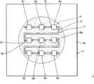
如图2中所示,形状保持构件19包含格子状部19a、外周框19b以及多个(在此实例中,两个)框垫19c。格子状部19a在平面图中呈格子形。外周框19b在平面图中呈圆形。框垫19c用于将荧光物质层7固定到衬底3。As shown in FIG. 2 , the
框垫19c布置在外周框19b的预定位置(在平面图中关于荧光物质层7的中心是对称的位置)。构成格子状部19a的线状构件20的端部附连到外周框19b。用以插入连接螺钉21的通孔23形成于框垫19c内,该连接螺钉将把荧光物质层7固定到衬底3,且螺丝孔25分别形成于衬底3内(见图3)。The
格子状部19a由多个线状构件20构造。在此实例中,总共使用八个线状构件20。线状构件20按下述形成:首先,准备两组四个线状构件20;每组的线状构件相互平行布置且在其间具有预定间隔(等间隔);两组线状构件20相互垂直地组装;并且它们在交叉处被固定。The
2.制造方法2. Manufacturing method
制造具有上述结构的发光源的方法包含实施步骤、密封步骤以及安装步骤。在实施步骤中,LED元件被实施在衬底上(该衬底包含衬底的布线图案与LED元件之间的连接)。在密封步骤中,实施步骤中的LED元件用密封构件密封(实际上,该步骤也是用于形成密封构件的步骤)。在安装步骤中,荧光物质层安装在衬底上。另外,用于形成荧光物质层的形成步骤可以在实施步骤和/或密封步骤之前执行或者与实施步骤和/或密封步骤同时执行。在任一情形中,形成步骤应在安装步骤之前执行。The method of manufacturing the light emitting source with the above structure includes implementing steps, sealing steps and installing steps. In the implementing step, the LED elements are implemented on a substrate (the substrate comprising connections between wiring patterns of the substrate and the LED elements). In the sealing step, the LED element in the implementing step is sealed with a sealing member (actually, this step is also a step for forming the sealing member). In the mounting step, the phosphor layer is mounted on the substrate. In addition, the forming step for forming the fluorescent substance layer may be performed before the implementing step and/or the sealing step or simultaneously with the implementing step and/or the sealing step. In either case, the forming step should be performed before the installing step.
在发光源制造方法的这些步骤中,实施步骤和密封步骤可以使用已知技术来执行。因此,这里将主要描述用于形成荧光物质层的步骤。Among the steps of the light emitting source manufacturing method, the implementing step and the sealing step can be performed using known techniques. Therefore, the steps for forming the phosphor layer will be mainly described here.
图5示出用于形成荧光物质层的方法。图5的左侧列示出荧光物质层的中间状态,图5的右侧列示出用于制作荧光物质层的中间状态的相应方法。FIG. 5 shows a method for forming a phosphor layer. The left column of FIG. 5 shows intermediate states of the phosphor layer, and the right column of FIG. 5 shows a corresponding method for producing the intermediate state of the phosphor layer.
荧光物质层是通过第一形成步骤、变形步骤、第二形成步骤和附连步骤制成。第一形成步骤形成平板状形状保持构件31(其对应于图5中的状态a并且严格来说是形状保持构件的原型),该平板状形状保持构件31是由外周框和格子状部构成,其中格子状部已经通过布置和相互连接多个线状构件而形成。变形步骤使平板状形状保持构件31变形为圆顶状形状保持构件33(其对应于图5中的状态b)。第二形成步骤通过半透明树脂形成树脂构件34(其对应于图5中的状态c)并利用圆顶状形状保持构件33作为骨架。附连步骤在第二形成步骤之后将框垫附连到外周框(略去说明)。The fluorescent substance layer is made through a first forming step, a deforming step, a second forming step and an attaching step. The first forming step forms a flat-plate shape maintaining member 31 (which corresponds to state a in FIG. 5 and is strictly speaking a prototype of the shape maintaining member), which is constituted by an outer peripheral frame and a lattice-like portion, Wherein the lattice portion has been formed by arranging and interconnecting a plurality of linear members. The deforming step deforms the flat plate-shaped shape maintaining member 31 into a dome-shaped shape maintaining member 33 (which corresponds to state b in FIG. 5 ). The second forming step forms the resin member 34 (which corresponds to state c in FIG. 5 ) with a translucent resin and utilizes the dome-shaped shape maintaining member 33 as a skeleton. The attaching step attaches the frame pad to the peripheral frame after the second forming step (illustration omitted).
通过例如压模方法(即,图5所示方法A),使用一对模具39和41,平板状形状保持构件31(状态a)可以转变成圆顶状形状保持构件33(状态b)。也就是说,该对模具39和41分别为阳模具39和阴模具41,其中阳模具39具有对应于圆顶状形状保持构件33的曲面的凸部39a,且阴模具41具有凹部41a。通过将模具39和41放置在一起且平板状形状保持构件31布置在其间,可以获得圆顶状形状保持构件33。By, for example, a compression molding method (ie, method A shown in FIG. 5 ), using a pair of molds 39 and 41, the flat-plate shape maintaining member 31 (state a) can be transformed into the dome shape maintaining member 33 (state b). That is, the pair of molds 39 and 41 are respectively a male mold 39 having a convex portion 39a corresponding to the curved surface of the dome-shaped shape maintaining member 33 and a female mold 41 having a concave portion 41a. The dome-shaped shape-maintaining member 33 can be obtained by placing the molds 39 and 41 together with the flat-plate-shaped shape-maintaining member 31 disposed therebetween.
用于基于圆顶状形状保持构件33(状态b)形成树脂构件34的方法B的一个实例为注模方法(图5所示方法B)。在此方法中,在圆顶状形状保持构件33布置在模具43内部的状态下,在模具43中已经预先形成的空间43a(其形状对应于荧光物质层)用半透明树脂来填充。这形成包含树脂构件34的荧光物质层35,圆顶状形状保持构件33在该树脂构件34中形成为骨架。One example of method B for forming the resin member 34 based on the dome-shaped shape maintaining member 33 (state b) is an injection molding method (method B shown in FIG. 5 ). In this method, in a state where the dome-shaped shape maintaining member 33 is arranged inside the mold 43, a space 43a (whose shape corresponds to the fluorescent substance layer) which has been preliminarily formed in the mold 43 is filled with a translucent resin. This forms the fluorescent substance layer 35 including the resin member 34 in which the dome-shaped shape maintaining member 33 is formed as a skeleton.
在附连步骤中,框垫例如通过焊接附连到外周框以获得荧光物质层7。In the attaching step, the frame pad is attached to the peripheral frame, for example by welding, to obtain the fluorescent substance layer 7 .
3.实例3. Examples
下文将描述具有上述结构的发光源1的实例。An example of the
在衬底3中,诸如绝缘氧化铝的陶瓷衬底用作绝缘层3a,且铝板用作金属基底3b。衬底3呈方形,每边的长度为30mm。注意,绝缘层3a厚0.2mm,金属基底3b厚1.0mm。In the
通过例如将大约10微米厚的铜箔蚀刻成预定图案,将布线图案13形成于绝缘层3a的主表面上。The
每个LED元件Dnm呈长方体形状,其高0.2mm且底面为1.0mm×1.0mm方形,且其为InGaN基LED用以发射蓝色光。沿行方向和列方向布置的邻近LED元件Dnm之间的距离(LED元件Dnm的中心到中心距离)约为5.0mm。Each LED element Dnm is in the shape of a cuboid with a height of 0.2 mm and a square bottom of 1.0 mm×1.0 mm, and it is an InGaN-based LED for emitting blue light. The distance between adjacent LED elements Dnm arranged in the row direction and the column direction (center-to-center distance of the LED elements Dnm) is about 5.0 mm.
密封构件5是由诸如硅树脂的树脂制成,且厚约1.2mm。此外,在平面图中,密封构件5呈直径为20mm的圆形。注意,即使硅树脂用作密封构件5的材料,密封构件5的形状仍得以保持,因为密封构件5本身的形状接近平坦。此外,即使密封构件5变形,也不会出现颜色不均匀,因为密封构件5不包含荧光物质材料。The sealing
在荧光物质层7中,形状保持构件19中的线状构件20是由不锈钢材料制成,树脂构件17是由硅树脂制成。荧光物质层7呈圆顶形状,其直径为25mm,高度为11mm。In the fluorescent substance layer 7, the
树脂构件17的硅树脂中将包含的荧光物质材料为例如发射黄色光的荧光物质材料。利用这种结构,从LED元件Dnm发射的蓝色光被荧光物质材料转换颜色,使得白色光从发光源1输出。对于例如中性白色光的情形,树脂构件17的硅树脂应含有8wt%至10wt%(优选地9.1wt%)的荧光物质材料。这是因为该含量百分比使得有可能减小期望色温随时间的变化。The fluorescent substance material to be contained in the silicone resin of the
构成形状保持构件19的线状构件20直径为0.2mm且垂直弹性模量为190GPa。形状保持构件19的格子形状形成为使得沿相同方向相互平行地延伸的线状构件20之间的距离L1、L2(见图2)为7.0mm。The
树脂构件17中使用的半透明硅树脂为基于甲基的橡胶状硅,其在可见光区域的折射率为1.42且透光效率为85%。树脂构件17厚1.0mm,且肖氏硬度为A20(遵照JISK6253)。The translucent silicone resin used in the
发明模式2Invention Mode 2
图6示出发明模式2中的照明装置。FIG. 6 shows a lighting device in invention mode 2. As shown in FIG.
照明装置51包含在发明模式1中描述的发光源1,安装在发光源1内用以散逸在照明期间来自发光源1的热的热沉53,经由热沉53支持发光源1的支撑物55,供电到发光源1以致使LED元件Dnm发光的照明电路57,在容纳照明电路57的状态下附连到支撑物55的壳体59,附连到壳体59的基底60,以及覆盖发光源1且固定到支撑物55和壳体59的球形灯罩62。The
热沉53是由例如铝制成,且其周缘壁设有用于散热的散热片。The
支撑物55在其一侧上附连着热沉53,在另一侧上附连着照明电路57。在当前实例中,支撑物55呈具有底部的圆柱体形状,其中底部附连着热沉53。The
在多个电子部件64a、64b等已经实施在衬底64c上的状态下,照明电路57以衬底64c通过使用锁定装置、固定装置等附连到支撑物55的方式来固定。In a state where a plurality of
基底60为例如属于E型(所谓的爱迪生类型)的E26型。基底60经由导线(未示出)与照明电路57连接。The
照明电路57为已知电路,其通过使用商业电源致使LED元件Dnm发光。照明电路57包含例如整流器电路和功率调节电路,其中整流器电路将从商业电源供应的交流功率整流为直流功率,功率调节电路调节已经由整流器电路整流的直流功率的电压值。The
球形灯罩62为例如A型。用于漫射从发光源1发射的光的光漫射膜62a形成于球形灯罩62的内表面上。球形灯罩62还具有开口侧端部62b,在开口侧端部62b插入支撑物55的周缘壁和在开口侧围绕该周缘壁的壳体59的端部(与基底相对放置的端部)之间的空间的状态下,该开口侧端部62b由固定剂58固定。注意,凸缘55a形成于支撑物55的整个外周以防止固定剂58流下。The
<变型例><Modification>
1.发光源1. Light source
在发明模式1中,多个(九个)LED元件Dnm由一个密封构件5密封,且荧光物质层7形成为圆顶形状。然而,不限于此,可以采用一个LED元件Dnm用一个密封构件密封的结构。In
(1)变型例1(1)
图7为变型例1中的发光源61的平面图。图8为沿箭头的方向看、沿着图7的B-B线截取的断面图。FIG. 7 is a plan view of a
如在发明模式1中那样,发光源61包含多个(在此实例中为九个)LED元件Dnm(n和m分别为2或者更大的自然数,在发明模式1中也是这样),LED元件Dnm实施于其上的衬底63,用于密封LED元件Dnm的密封构件Rnm,以及荧光物质层65。As in
密封构件Rnm中的n和m分别对应于LED元件Dnm中的n和m。如同在发明模式1中那样,密封构件Rnm是由硅树脂等制成。n and m in the sealing member Rnm correspond to n and m in the LED element Dnm, respectively. As in
如在发明模式1中那样,荧光物质层65包含形状保持构件66和树脂构件67,其中形状保持构件66嵌在树脂构件67内作为其骨架。此外,形状保持构件66包含由不锈钢材料制成的线状构件66a,且树脂构件67由硅树脂制成。As in
如图7和8中所示,荧光物质层65在分别对应于LED元件Dnm的位置处包含凸状部Cnm。凸状部Cnm中的n和m分别对应于LED元件Dnm中的n和m。As shown in FIGS. 7 and 8 , the
每个凸状部Cnm呈圆顶形状。就凸状部Cnm的圆顶形状而言,其圆弧的半径被确定为使得圆弧的中心位于光发射的中心。这里提到的光发射中心为每个LED元件的中心。Each convex portion Cnm has a dome shape. As for the dome shape of the convex portion Cnm, the radius of its arc is determined such that the center of the arc is located at the center of light emission. The light emission center mentioned here is the center of each LED element.
如图7中所示,形状保持构件66包含格子状部、外周框68a和框垫68b。格子状部在平面图中呈格子形状。外周框68a在平面图中呈方形。框垫68b用于将荧光物质层65固定到衬底63。As shown in FIG. 7 , the shape maintaining member 66 includes a lattice portion, an outer
按照框垫68b通过固定螺丝69固定到衬底63的方式,荧光物质层65固定到衬底63。注意,实际上存在的线状构件66a在图7中被B-B线遮住。The
(2)其它(2) Others
在变型例1中,荧光物质层65的密封构件Rnm和凸状部Cnm是与LED元件Dnm一一对应分别形成的。然而,本发明不限于这种结构。例如,多个LED元件可以用一个密封构件密封,且荧光物质层在对应于密封构件的位置处可包含凸状部。作为另一实例,多个LED元件可以用一个密封构件密封,且一个凸状部可以与该密封构件对应地设置。作为又一实例,多个LED元件可以用一个密封构件密封,且多个凸状部可以设在分别对应于多个LED元件的位置处(这导致与LED元件一样多的凸状部)。In
注意,衬底、密封构件、凸状部和荧光物质层的形状不限于在发明模式1和变型例1所描述的形状,而可以是其它形状。Note that the shapes of the substrate, sealing member, convex portion, and fluorescent substance layer are not limited to those described in
2.模制树脂产品(荧光物质层)2. Molded resin product (fluorescent substance layer)
本发明的模制树脂产品不限于上文在发明模式1所述的结构,而是可具有部分地或者完全不同的形状。在上述的发明模式1和变型例1中,荧光物质层包含形状保持构件和树脂构件。然而,不限于此,荧光物质层可另外包含具有其它功能的其它构件。The molded resin product of the present invention is not limited to the structure described above in
(1)变型例2-1(1) Modification 2-1
图9A为变型例2-1中模制树脂产品的纵向断面图。Fig. 9A is a longitudinal sectional view of a molded resin product in Modification 2-1.
如在发明模式1中那样,模制树脂产品70包含形状保持构件71、树脂构件72a和树脂构件72b,其中树脂构件72a由包含荧光物质材料的半透明树脂制成,树脂构件72b包含光漫射材料。例如,包含荧光物质材料的树脂构件72a形成于形状保持构件71内侧(位于LED元件侧),包含光漫射材料的树脂构件72b形成于形状保持构件71外侧,使得树脂构件72a和树脂构件72b的形状由形状保持构件71保持。As in
同样,在模制树脂产品70中,用于将模制树脂产品70固定到衬底的框垫73设于外周框内。在变型例2中,模制树脂产品70整体上呈圆顶形状。然而,如在变型例1那样(同样如在该变型例中描述的其它实例中那样),多个凸状部可分别与密封构件和LED元件相对应地设置。Also, in the molded resin product 70, frame pads 73 for fixing the molded resin product 70 to the substrate are provided in the peripheral frame. In Modification 2, the molded resin product 70 has a dome shape as a whole. However, as in Modification 1 (also as in other examples described in this modification), a plurality of convex portions may be provided corresponding to the sealing member and the LED element, respectively.
在当前变型例2-1中,解释了包含光漫射材料(例如硅石)的树脂构件(72b)。然而,不限于此,该树脂构件可包含其它材料。In the present Modification 2-1, a resin member ( 72 b ) containing a light-diffusing material such as silica is explained. However, not limited thereto, the resin member may contain other materials.
再者,在发明模式1以及变型例1和2-1中,一个树脂构件包含具有一种功能的一种材料(荧光物质材料或者光漫射材料)。然而,一个树脂构件可包含具有多种功能的多种材料。Also, in
(2)凸状部的形状(2) Shape of convex part
在发明模式等中,凸状部呈圆顶形状(圆弧或者椭圆弧)。然而,不限于此,凸状部可以例如呈圆锥体(包含截顶圆锥体)形状或者角锥体(包含截顶角锥体)形状。然而,从防止出现颜色不均匀的角度而言,优选的是,凸状部的形状允许从光源发射并且通过模制树脂产品的光的光路径长度基本上相等。In the invention mode or the like, the convex portion has a dome shape (arc or ellipse). However, not limited thereto, the convex portion may, for example, be in the shape of a cone (including a truncated cone) or a pyramid (including a truncated pyramid). However, from the viewpoint of preventing occurrence of color unevenness, it is preferable that the shape of the convex portion allows the optical path lengths of light emitted from the light source and passed through the molded resin product to be substantially equal.
(3)形状(3) shape
在发明模式等中,模制树脂产品包含凸状部。然而,不限于此,模制树脂产品可以是如图14中所示的平板状形状,或者可以具有凹状部。也就是说,只要模制树脂产品在其内部或者外部包含形状保持构件,无论树脂构件是凝胶状还是橡胶状,模制树脂产品的形状得以保持。In the invention mode and the like, a molded resin product includes a convex portion. However, not limited thereto, the molded resin product may be in a flat plate-like shape as shown in FIG. 14 , or may have a concave portion. That is, as long as the molded resin product contains a shape maintaining member inside or outside thereof, the shape of the molded resin product is maintained regardless of whether the resin member is gel-like or rubber-like.
图9B为变型例2-2中模制树脂产品的纵向断面图。Fig. 9B is a longitudinal sectional view of a molded resin product in Modification 2-2.
如图9B中所示,模制树脂产品76包含凹状部76a,该凹状部与从LED元件105发射的光的光发射方向相对应地弯曲。注意,变型例2-2中的发光源74包含LED元件105、密封构件75和模制树脂产品76。As shown in FIG. 9B , the molded
(4)其它(4) Others
在发明模式1中,使用发射黄色光的荧光物质材料。然而,不限于此,可以使用其它荧光物质材料。注意,LED元件不限于发射蓝色光的LED元件。因此,供使用的荧光物质材料可以依据从LED元件发射的光的颜色来确定。In
在发明模式1等中,使用硅树脂。然而,不限于此,可以使用其它树脂。例如,可以使用氟树脂代替硅树脂,或者可以使用硅树脂和氟树脂二者。In
将凝胶状或者橡胶状树脂用作树脂构件的原因在于,其提供低的应力且在树脂构件的模制期间不易导致破裂,因而容易模制。此外,凝胶状或者橡胶状树脂通常具有高的热阻,不易通过劣化变脆,且由于其柔软性质,其由于劣化而变脆需要很长的时间。注意,为了获得这种效果,优选地半透明树脂的硬度为A80或更小。The reason for using a gel-like or rubber-like resin as the resin member is that it provides low stress and does not easily cause cracks during molding of the resin member, and thus is easy to mold. In addition, gel-like or rubber-like resins generally have high thermal resistance, are not easily made brittle by deterioration, and take a long time to become brittle by deterioration due to their soft nature. Note that in order to obtain this effect, it is preferable that the hardness of the translucent resin is A80 or less.
3.用于制造模制树脂产品的方法3. Method for manufacturing molded resin products
根据在发明模式1中解释的用于制造模制树脂产品的方法,平板状形状保持构件被转变成圆顶状形状保持构件,随后半透明树脂模制成树脂构件,使得圆顶状形状保持构件成为树脂构件的骨架。然而,不限于此方法,模制树脂产品可以通过另外的方法形成。According to the method for manufacturing a molded resin product explained in
(1)变型例3(1)
图10示出变型例3中用于制造模制树脂产品的方法。图10的左侧列示出荧光物质层的中间状态,以及图10的右侧列示出用于制作模制树脂产品的中间状态的相应方法。FIG. 10 shows a method for manufacturing a molded resin product in
模制树脂产品84是通过第一形成步骤、第二形成步骤、变形步骤和附连步骤制成。第一形成步骤形成由外周框77b和格子状部构成的平板状形状保持构件77(其对应于图10中的状态d),其中格子状部已经通过将多个线状构件77a布置并相互连接而形成。第二形成步骤通过半透明树脂形成树脂构件78(其对应于图10中的状态e)并利用平板状的形状保持构件71作为骨架。变形步骤使树脂构件78变形成圆顶形状(其对应于图10中的状态f)。附连步骤在变形步骤之后将框垫附连到外周框77b。The molded
基于平板状形状保持构件77(状态d)形成树脂构件78的方法的一个实例为注模方法(图10所示方法C)。在此方法中,在平板状形状保持构件77布置在模具80中已经预先形成的空间80a内部的状态下,空间80a(其形状对应于在状态e呈平板状的模制树脂产品84的三维形状)用半透明树脂填充。这形成由形状保持构件71支撑的平板状树脂构件81。One example of a method of forming the
通过例如压模方法(即,图10所示方法D),使用一对模具82和83,平板状树脂构件81(状态e)可以转变成圆顶状模制树脂产品84(状态f)。也就是说,该对模具82和83分别为阳模具82和阴模具83,其中阳模具82具有与模制树脂产品84的曲面对应的凸部82a,且阴模具83具有凹部83a。通过将模具82和83放置在一起且平板状树脂构件81布置在其间,可以获得模制树脂产品84。The plate-like resin member 81 (state e) can be transformed into a dome-shaped molded resin product 84 (state f) by, for example, a compression molding method (ie, method D shown in FIG. 10 ) using a pair of
(2)其它(2) Others
在发明模式1和变型例3中,主要使用压模方法和注模方法。然而,不限于这些方法,例如可以使用转移模制方法形成模制树脂产品。再者,在发明模式等中,模制树脂产品经由固定到外周框的框垫而附连到衬底等。然而,不限于这种结构,例如外周框可以直接附连到衬底等。In
用于将外周框直接附连到衬底的方法的一个实例如下。首先准备直径可以减小的字母C形状的外周框。另外,在衬底中的预定附连区域处,形成直径比字母C形状的外周框小的槽,随后通过减小该框的直径而将外周框装配到槽内。One example of a method for directly attaching the perimeter frame to the substrate is as follows. First, a C-shaped outer peripheral frame whose diameter can be reduced is prepared. In addition, at a predetermined attachment area in the substrate, a groove having a smaller diameter than the outer peripheral frame in the shape of a letter C is formed, and then the outer peripheral frame is fitted into the groove by reducing the diameter of the frame.
4.形状保持构件4. Shape-retaining member
(1)材料(1) Material
发明模式1中构成形状保持构件的线状构件是由不锈钢材料制成的。然而,不限于不锈钢材料,形状保持构件可以由可以保持凝胶状或者橡胶状树脂构件的形状的任何其它材料制成。例如,该材料可以是下述中的一种:另一种金属(钨、铁、铜等)、玻璃、陶瓷和树脂,或者它们中两种或更多种的组合。The linear member constituting the shape maintaining member in
此外,由于线状构件嵌在模制树脂产品(荧光物质层)内,它们在接收从发光源发射的光时会形成阴影。因此优选地,线状构件直径为0.4mm或更小。再者,当考虑线状构件所形成的诸如格子形状的形状时,优选地,线状构件直径为0.3mm或更小。当考虑到可加工性时,优选地,线状构件的垂直弹性模量的范围为从130GPa到190GPa,130GPa和190GPa也包含在内。In addition, since the linear members are embedded in the molded resin product (fluorescent substance layer), they form shadows when receiving light emitted from a light emitting source. Therefore preferably, the diameter of the linear member is 0.4 mm or less. Also, when a shape such as a lattice shape formed by the linear member is considered, it is preferable that the linear member has a diameter of 0.3 mm or less. When workability is considered, it is preferable that the vertical elastic modulus of the linear member ranges from 130 GPa to 190 GPa, 130 GPa and 190 GPa are included.
(2)形状(2) shape
在发明模式1中,形状保持构件在平面图中呈格子形状。然而,不限于此,形状保持构件可以为除此之外的其他形状。In
图11A至11F示出变型例中形状保持构件的各种结构。11A to 11F show various structures of the shape maintaining member in modified examples.
图11A所示形状保持构件85具有这样的结构,其中形成为具有不同半径的同心圆的多个(在此实例中为三个)线状构件85a布置成具有相同中心。此结构起到的作用为通过调节圆的位置、节距等,使得尤其是形状需要被保持的部分的力度增大。例如,更多数目的圆可以布置在外周。The shape maintaining member 85 shown in FIG. 11A has a structure in which a plurality (three in this example) of linear members 85a formed as concentric circles having different radii are arranged to have the same center. The role of this structure is to increase the strength of the part where the shape needs to be maintained, especially by adjusting the position and pitch of the circle. For example, a greater number of circles may be arranged on the outer periphery.
图11B所示形状保持构件86具有这样的结构,其中多个(在此实例中为四个)线状构件86a沿圆周方向规则间隔地按放射状布置。此结构产生的效果为增强了对抗从上方(垂直于纸面的方向)施加的应力(压应力)而保持形状的力。The
图11C所示形状保持构件87具有这样的结构,其中多个(在此实例中为七个)线状构件87a和87b被使用,其中形成为具有不同半径的同心圆的三个线状构件87a布置成具有相同中心,其余四个线状构件87b沿圆周方向规则间隔地按放射状布置。此结构产生的效果为增强了对抗从每个方向施加的变形应力而保持形状的力。The
图11D所示形状保持构件88具有这样的结构,其中形成为螺旋形状的一个线状构件88a布置成使得其一个端部靠近中心布置,而线状构件88a围绕中心缠绕而逐渐朝向圆周(即,朝向线状构件的另一个端部)延伸。此结构的效果是通过使用一个线状构件来形成形状保持构件。The
图11E所示形状保持构件89具有这样的结构,其中多个(在此实例中为五个)线状构件89a相互平行地布置。此结构产生的效果为容易形成形状保持构件(容易实施),因为它只需要将线状构件相互平行地布置。The shape maintaining member 89 shown in FIG. 11E has a structure in which a plurality (five in this example) of linear members 89a are arranged in parallel to each other. This structure produces the effect that the shape retaining member is easily formed (easy to implement) because it only needs to arrange the linear members in parallel to each other.
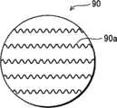
图11F所示形状保持构件90具有与上述图11E所示形状保持构件89的结构相似的结构,只是每个线状构件呈线圈形状。此结构产生的效果为增大了形状保持构件(线状构件)与树脂之间的接触面积,防止出现模制树脂产品破裂或脱落,因而提高了模制树脂产品的可靠性。The
注意,形状保持构件的结构可以是上述六种结构的任意组合。例如,一件图11F所示线圈状的形状保持构件90可以整体上形成为如图11D中所示的螺旋形状。Note that the structure of the shape retaining member may be any combination of the above six structures. For example, a piece of coil-shaped
在这些变型例中,形状保持构件的外周在平面图中呈圆的形状。然而,不限于此,形状保持构件的外周可以是例如三角形的多边形的形状,或者是椭圆形的形状。此外,外周框可以由线状构件或者带状构件来构造。当外周框用线状构件来构造时,该线状构件可能会在厚度、材料(包含弹性模量不同的材料)等方面不同于格子状构件中使用的线状构件。In these modifications, the outer periphery of the shape maintaining member has a circular shape in plan view. However, not limited thereto, the outer periphery of the shape maintaining member may be in the shape of a polygon such as a triangle, or in the shape of an ellipse. In addition, the peripheral frame may be constructed of a wire-shaped member or a belt-shaped member. When the outer peripheral frame is constructed with a linear member, the linear member may be different from the linear member used in the lattice-shaped member in terms of thickness, material (including a material having a different modulus of elasticity), and the like.
5.照明装置5. Lighting device
在发明模式2中,模制树脂产品(荧光物质层)7包含在发光源1内,并且发光源1附连到衬底3。然而,模制树脂产品可以不包含在发光源内。In invention mode 2 , molded resin product (fluorescent substance layer) 7 is contained in light emitting
图12示出发明模式2中的照明装置。Fig. 12 shows a lighting device in invention mode 2.
照明装置91包含发光源92、安装在发光源92内用于散逸在照明期间来自发光源92的热的热沉93、经由热沉93支撑发光源92的支撑物94、供电到发光源92以致使LED元件Dnm发光的照明电路57、在容纳照明电路57的状态下附连到支撑物94的壳体59、附连到壳体59的基底60、覆盖发光源92且固定到支撑物94的模制树脂产品(荧光物质层)95、以及覆盖模制树脂产品95且固定到支撑物94和壳体59的球形灯罩62。The
如上所述,模制树脂产品95附连到支撑物94,发光源92附连到该支撑物94。如图12中所示,模制树脂产品95整体上呈圆的形状。这种结构还允许从发光源92发射且通过模制树脂产品95的光的光路径长度相等,防止出现颜色不均匀。As described above, the molded
工业适用性Industrial applicability
本发明的发光源和照明装置适用于设有由凝胶状或者橡胶状树脂制成的荧光物质层的发光源和照明装置,该荧光物质层可以长时间保持其形状且可以容易地实施。The light emitting source and lighting device of the present invention are suitable for a light emitting source and lighting device provided with a fluorescent substance layer made of gel-like or rubber-like resin, which can maintain its shape for a long time and can be easily implemented.
Claims (19)
Translated fromChineseApplications Claiming Priority (3)
| Application Number | Priority Date | Filing Date | Title |
|---|---|---|---|
| JP2008-087734 | 2008-03-28 | ||
| JP2008087734 | 2008-03-28 | ||
| PCT/JP2009/001175WO2009119038A2 (en) | 2008-03-28 | 2009-03-17 | Molded resin product, semiconductor light-emitting source, lighting device, and method for manufacturing molded resin product |
Publications (2)
| Publication Number | Publication Date |
|---|---|
| CN101946337A CN101946337A (en) | 2011-01-12 |
| CN101946337Btrue CN101946337B (en) | 2012-12-05 |
Family
ID=41036763
Family Applications (1)
| Application Number | Title | Priority Date | Filing Date |
|---|---|---|---|
| CN2009801054735AActiveCN101946337B (en) | 2008-03-28 | 2009-03-17 | Molded resin product, semiconductor light emitting source, lighting device, and manufacturing method of molded resin product |
Country Status (6)
| Country | Link |
|---|---|
| US (1) | US8890186B2 (en) |
| EP (1) | EP2263266B1 (en) |
| JP (1) | JP5341915B2 (en) |
| CN (1) | CN101946337B (en) |
| TW (1) | TW200950024A (en) |
| WO (1) | WO2009119038A2 (en) |
Families Citing this family (55)
| Publication number | Priority date | Publication date | Assignee | Title |
|---|---|---|---|---|
| US9412926B2 (en) | 2005-06-10 | 2016-08-09 | Cree, Inc. | High power solid-state lamp |
| DE102009040148A1 (en) | 2009-09-04 | 2011-03-10 | Osram Opto Semiconductors Gmbh | Conversion medium body, optoelectronic semiconductor chip and method for producing an optoelectronic semiconductor chip |
| JP4790058B2 (en)* | 2009-12-07 | 2011-10-12 | シャープ株式会社 | Lighting device |
| US8466611B2 (en) | 2009-12-14 | 2013-06-18 | Cree, Inc. | Lighting device with shaped remote phosphor |
| US9024517B2 (en) | 2010-03-03 | 2015-05-05 | Cree, Inc. | LED lamp with remote phosphor and diffuser configuration utilizing red emitters |
| US9500325B2 (en) | 2010-03-03 | 2016-11-22 | Cree, Inc. | LED lamp incorporating remote phosphor with heat dissipation features |
| JP2013528893A (en)* | 2010-03-03 | 2013-07-11 | クリー インコーポレイテッド | LED lamp using remote phosphor and diffuser configuration |
| US9057511B2 (en)* | 2010-03-03 | 2015-06-16 | Cree, Inc. | High efficiency solid state lamp and bulb |
| US9275979B2 (en) | 2010-03-03 | 2016-03-01 | Cree, Inc. | Enhanced color rendering index emitter through phosphor separation |
| WO2011109092A2 (en)* | 2010-03-03 | 2011-09-09 | Cree, Inc. | Led lamp with remote phosphor and diffuser configuration |
| US9625105B2 (en) | 2010-03-03 | 2017-04-18 | Cree, Inc. | LED lamp with active cooling element |
| US8562161B2 (en) | 2010-03-03 | 2013-10-22 | Cree, Inc. | LED based pedestal-type lighting structure |
| US9316361B2 (en) | 2010-03-03 | 2016-04-19 | Cree, Inc. | LED lamp with remote phosphor and diffuser configuration |
| US8632196B2 (en) | 2010-03-03 | 2014-01-21 | Cree, Inc. | LED lamp incorporating remote phosphor and diffuser with heat dissipation features |
| CN103003625B (en)* | 2010-03-03 | 2017-03-22 | 克利公司 | Solid state lamp |
| US9062830B2 (en) | 2010-03-03 | 2015-06-23 | Cree, Inc. | High efficiency solid state lamp and bulb |
| US10359151B2 (en) | 2010-03-03 | 2019-07-23 | Ideal Industries Lighting Llc | Solid state lamp with thermal spreading elements and light directing optics |
| US8882284B2 (en) | 2010-03-03 | 2014-11-11 | Cree, Inc. | LED lamp or bulb with remote phosphor and diffuser configuration with enhanced scattering properties |
| US9310030B2 (en) | 2010-03-03 | 2016-04-12 | Cree, Inc. | Non-uniform diffuser to scatter light into uniform emission pattern |
| US8931933B2 (en) | 2010-03-03 | 2015-01-13 | Cree, Inc. | LED lamp with active cooling element |
| JP4932064B2 (en)* | 2010-03-11 | 2012-05-16 | パナソニック株式会社 | Light emitting module, light source device, liquid crystal display device, and method for manufacturing light emitting module |
| USD658603S1 (en)* | 2010-06-15 | 2012-05-01 | Toshiba Lighting & Technology Corporation | Light emitting diode module |
| DE102010030863A1 (en)* | 2010-07-02 | 2012-01-05 | Osram Gesellschaft mit beschränkter Haftung | LED lighting device and method for producing an LED lighting device |
| US8835199B2 (en)* | 2010-07-28 | 2014-09-16 | GE Lighting Solutions, LLC | Phosphor suspended in silicone, molded/formed and used in a remote phosphor configuration |
| US10451251B2 (en) | 2010-08-02 | 2019-10-22 | Ideal Industries Lighting, LLC | Solid state lamp with light directing optics and diffuser |
| WO2012018277A1 (en)* | 2010-08-04 | 2012-02-09 | Общество с ограниченной ответственностью "ДиС ПЛЮС" | Lighting device |
| JP2012074249A (en)* | 2010-09-29 | 2012-04-12 | Panasonic Corp | Lamp |
| US8624271B2 (en)* | 2010-11-22 | 2014-01-07 | Cree, Inc. | Light emitting devices |
| KR101781424B1 (en) | 2010-11-26 | 2017-09-26 | 서울반도체 주식회사 | LED Illumination Equipment |
| USD653366S1 (en) | 2010-12-19 | 2012-01-31 | Cree, Inc. | LED lamp |
| USD660990S1 (en) | 2011-01-19 | 2012-05-29 | Cree, Inc. | LED lamp |
| US9068701B2 (en) | 2012-01-26 | 2015-06-30 | Cree, Inc. | Lamp structure with remote LED light source |
| US9234655B2 (en) | 2011-02-07 | 2016-01-12 | Cree, Inc. | Lamp with remote LED light source and heat dissipating elements |
| US11251164B2 (en) | 2011-02-16 | 2022-02-15 | Creeled, Inc. | Multi-layer conversion material for down conversion in solid state lighting |
| US10098197B2 (en) | 2011-06-03 | 2018-10-09 | Cree, Inc. | Lighting devices with individually compensating multi-color clusters |
| US8922108B2 (en)* | 2011-03-01 | 2014-12-30 | Cree, Inc. | Remote component devices, systems, and methods for use with light emitting devices |
| US20120236532A1 (en)* | 2011-03-14 | 2012-09-20 | Koo Won-Hoe | Led engine for illumination |
| US8754440B2 (en)* | 2011-03-22 | 2014-06-17 | Tsmc Solid State Lighting Ltd. | Light-emitting diode (LED) package systems and methods of making the same |
| WO2013080422A1 (en)* | 2011-11-28 | 2013-06-06 | パナソニック株式会社 | Light emitting module and lamp |
| WO2013088619A1 (en)* | 2011-12-16 | 2013-06-20 | パナソニック株式会社 | Light-emitting module, and illumination light source and illumination device using same |
| EP2639491A1 (en)* | 2012-03-12 | 2013-09-18 | Panasonic Corporation | Light Emitting Device, And Illumination Apparatus And Luminaire Using Same |
| US9488359B2 (en) | 2012-03-26 | 2016-11-08 | Cree, Inc. | Passive phase change radiators for LED lamps and fixtures |
| US9612002B2 (en)* | 2012-10-18 | 2017-04-04 | GE Lighting Solutions, LLC | LED lamp with Nd-glass bulb |
| DE102012220264A1 (en)* | 2012-11-07 | 2014-05-08 | Osram Gmbh | Bulb for reflector lamp, has scattering piston which is arranged equally from base element which supports light emitting component within litter piston, so that scattering piston scatters light diffusely in specific portion |
| US20140198506A1 (en)* | 2013-01-14 | 2014-07-17 | Genesis Photonics Inc. | Lighting device |
| KR102037866B1 (en)* | 2013-02-05 | 2019-10-29 | 삼성전자주식회사 | Electronic device |
| TWI510741B (en)* | 2013-05-27 | 2015-12-01 | Genesis Photonics Inc | Illuminating device |
| CN103367612B (en)* | 2013-07-03 | 2016-04-13 | 深圳雷曼光电科技股份有限公司 | LED encapsulation structure and technique |
| JP6252753B2 (en)* | 2013-12-20 | 2017-12-27 | パナソニックIpマネジメント株式会社 | LIGHT EMITTING DEVICE, LIGHTING DEVICE, AND MOUNTING BOARD |
| US9360188B2 (en) | 2014-02-20 | 2016-06-07 | Cree, Inc. | Remote phosphor element filled with transparent material and method for forming multisection optical elements |
| USD749774S1 (en)* | 2014-12-03 | 2016-02-16 | Anthony I. Provitola | Reflector for hidden light strip |
| USD786808S1 (en) | 2015-05-20 | 2017-05-16 | Citizen Electronics Co., Ltd. | Light-emitting diode |
| USD789308S1 (en)* | 2015-10-23 | 2017-06-13 | Citizen Electronics Co., Ltd. | Light-emitting diode |
| WO2020127163A1 (en)* | 2018-12-21 | 2020-06-25 | Signify Holding B.V. | Filament lamp |
| US11920738B2 (en)* | 2020-06-04 | 2024-03-05 | Xiamen Eco Lighting Co. Ltd. | LED bulb apparatus with substrate having light transmission than 50% |
Citations (1)
| Publication number | Priority date | Publication date | Assignee | Title |
|---|---|---|---|---|
| EP1220332A2 (en)* | 2000-12-22 | 2002-07-03 | Sanken Electric Co., Ltd. | A light permeable fluorescent cover for light emitting diode |
Family Cites Families (29)
| Publication number | Priority date | Publication date | Assignee | Title |
|---|---|---|---|---|
| JPS5936837B2 (en)* | 1977-04-05 | 1984-09-06 | 株式会社東芝 | Optical semiconductor device |
| US4959762A (en)* | 1988-09-08 | 1990-09-25 | General Electric Company | Luminaire containment means for lamp rupturing |
| JP2630075B2 (en)* | 1991-01-22 | 1997-07-16 | 日本電気株式会社 | Optical dome for flying objects |
| US5725303A (en)* | 1996-09-30 | 1998-03-10 | Lin; Shih-Ming | Lampshade and guard netting arrangement of a halogen lamp |
| US6291369B1 (en) | 1998-04-08 | 2001-09-18 | Dai Nippon Printing Co., Ltd. | Resin molding |
| JP4406490B2 (en)* | 2000-03-14 | 2010-01-27 | 株式会社朝日ラバー | Light emitting diode |
| EP1219401A3 (en) | 2000-12-29 | 2004-02-04 | Nokia Corporation | Resin injection molded article with reinforcing or decorative core |
| JP2005166733A (en) | 2003-11-28 | 2005-06-23 | Matsushita Electric Works Ltd | Light emitting device |
| JP4471356B2 (en) | 2004-04-23 | 2010-06-02 | スタンレー電気株式会社 | Semiconductor light emitting device |
| US7855395B2 (en) | 2004-09-10 | 2010-12-21 | Seoul Semiconductor Co., Ltd. | Light emitting diode package having multiple molding resins on a light emitting diode die |
| JP2007335080A (en)* | 2004-09-17 | 2007-12-27 | Light Boy Co Ltd | Lighting device |
| CA2487697A1 (en)* | 2004-11-02 | 2006-05-02 | John C. Borland | Molding thin wall parts in a closed mold |
| JP4608294B2 (en)* | 2004-11-30 | 2011-01-12 | 日亜化学工業株式会社 | RESIN MOLDED BODY, SURFACE MOUNTED LIGHT EMITTING DEVICE AND METHOD FOR PRODUCING THEM |
| JP4591071B2 (en)* | 2004-12-20 | 2010-12-01 | 日亜化学工業株式会社 | Semiconductor device |
| TWI419375B (en) | 2005-02-18 | 2013-12-11 | Nichia Corp | Light-emitting device with lens for controlling light distribution characteristics |
| JP2007035802A (en)* | 2005-07-25 | 2007-02-08 | Matsushita Electric Works Ltd | Light-emitting device |
| WO2007015732A2 (en) | 2005-08-01 | 2007-02-08 | Intex Recreation Corp. | A method of varying the color of light emitted by a light-emitting device |
| JP2007049019A (en)* | 2005-08-11 | 2007-02-22 | Koha Co Ltd | Light emitting device |
| JP3992059B2 (en)* | 2005-11-21 | 2007-10-17 | 松下電工株式会社 | Method for manufacturing light emitting device |
| JP2007180234A (en)* | 2005-12-27 | 2007-07-12 | Matsushita Electric Ind Co Ltd | Luminescent light source and lighting fixture |
| JP4996101B2 (en)* | 2006-02-02 | 2012-08-08 | 新光電気工業株式会社 | Semiconductor device and manufacturing method of semiconductor device |
| JP5130680B2 (en)* | 2006-03-02 | 2013-01-30 | 日亜化学工業株式会社 | Semiconductor device and method for forming the same |
| JP4353196B2 (en)* | 2006-03-10 | 2009-10-28 | パナソニック電工株式会社 | Light emitting device |
| JP2007271834A (en)* | 2006-03-31 | 2007-10-18 | Mitsui Chemicals Inc | Resin composition for reflection plate and reflection plate |
| JP2007305785A (en)* | 2006-05-11 | 2007-11-22 | Nichia Chem Ind Ltd | Light emitting device |
| JP2007311445A (en)* | 2006-05-17 | 2007-11-29 | Stanley Electric Co Ltd | Semiconductor light emitting device and manufacturing method thereof |
| TWI428396B (en) | 2006-06-14 | 2014-03-01 | Shinetsu Chemical Co | Phosphor-filled curable silicone resin composition and cured product thereof |
| US20080029720A1 (en) | 2006-08-03 | 2008-02-07 | Intematix Corporation | LED lighting arrangement including light emitting phosphor |
| TWM313317U (en) | 2006-12-01 | 2007-06-01 | E Pin Optical Industry Co Ltd | LED assembly having molded glass lens |
- 2009
- 2009-03-17CNCN2009801054735Apatent/CN101946337B/enactiveActive
- 2009-03-17WOPCT/JP2009/001175patent/WO2009119038A2/enactiveApplication Filing
- 2009-03-17USUS12/867,728patent/US8890186B2/enactiveActive
- 2009-03-17EPEP09725291.0Apatent/EP2263266B1/ennot_activeNot-in-force
- 2009-03-17JPJP2010543753Apatent/JP5341915B2/enactiveActive
- 2009-03-23TWTW098109345Apatent/TW200950024A/enunknown
Patent Citations (1)
| Publication number | Priority date | Publication date | Assignee | Title |
|---|---|---|---|---|
| EP1220332A2 (en)* | 2000-12-22 | 2002-07-03 | Sanken Electric Co., Ltd. | A light permeable fluorescent cover for light emitting diode |
Also Published As
| Publication number | Publication date |
|---|---|
| JP2011512648A (en) | 2011-04-21 |
| EP2263266B1 (en) | 2015-05-06 |
| TW200950024A (en) | 2009-12-01 |
| EP2263266A2 (en) | 2010-12-22 |
| US20110084297A1 (en) | 2011-04-14 |
| WO2009119038A3 (en) | 2009-12-10 |
| WO2009119038A4 (en) | 2010-02-18 |
| US8890186B2 (en) | 2014-11-18 |
| WO2009119038A2 (en) | 2009-10-01 |
| CN101946337A (en) | 2011-01-12 |
| JP5341915B2 (en) | 2013-11-13 |
Similar Documents
| Publication | Publication Date | Title |
|---|---|---|
| CN101946337B (en) | Molded resin product, semiconductor light emitting source, lighting device, and manufacturing method of molded resin product | |
| CN103180661B (en) | Lamp and lighting device | |
| CN102334202B (en) | Light-emitting module and illumination apparatus | |
| CN102414851B (en) | The manufacture method of light emitting module, light supply apparatus, liquid crystal indicator and light emitting module | |
| CN103339751B (en) | Light emitting module and use the lamp of this light emitting module | |
| JP5459623B2 (en) | Lighting device | |
| CN103649619B (en) | Lighting devices and lighting devices | |
| US20040201025A1 (en) | High power light emitting diode | |
| EP2446190A2 (en) | Led lamp with a wavelength converting layer | |
| WO2014030289A1 (en) | Lamp and lighting device | |
| JPWO2014045523A1 (en) | Illumination light source and illumination device | |
| WO2013024557A1 (en) | Led lamp and lighting device | |
| JP5677806B2 (en) | LED bulb | |
| JP5270991B2 (en) | Light emitting device and lighting apparatus | |
| CN203118993U (en) | Light emitting device and lighting device | |
| JP6508556B2 (en) | lighting equipment | |
| JP2011054340A (en) | Lighting device | |
| JP5718199B2 (en) | Light bulb-type lighting device | |
| JP5839864B2 (en) | LED bulb | |
| JP2012064362A (en) | Lighting system | |
| JP2010199513A (en) | Lighting emitting device and lighting system including the light emitting device | |
| JP5664964B2 (en) | Lamp with lamp and lighting equipment | |
| CN204240087U (en) | Lamp and lighting device | |
| JP5948666B2 (en) | Illumination light source and illumination device | |
| JP2013012453A (en) | Led lamp |
Legal Events
| Date | Code | Title | Description |
|---|---|---|---|
| C06 | Publication | ||
| PB01 | Publication | ||
| C10 | Entry into substantive examination | ||
| SE01 | Entry into force of request for substantive examination | ||
| C14 | Grant of patent or utility model | ||
| GR01 | Patent grant |