CN101944643A - The battery component that is used for motor vehicle driven by mixed power or motor vehicle - Google Patents
The battery component that is used for motor vehicle driven by mixed power or motor vehicleDownload PDFInfo
- Publication number
- CN101944643A CN101944643ACN2010102248291ACN201010224829ACN101944643ACN 101944643 ACN101944643 ACN 101944643ACN 2010102248291 ACN2010102248291 ACN 2010102248291ACN 201010224829 ACN201010224829 ACN 201010224829ACN 101944643 ACN101944643 ACN 101944643A
- Authority
- CN
- China
- Prior art keywords
- battery
- battery module
- storage
- prismatic
- housing
- Prior art date
- Legal status (The legal status is an assumption and is not a legal conclusion. Google has not performed a legal analysis and makes no representation as to the accuracy of the status listed.)
- Granted
Links
Images


Classifications
- H—ELECTRICITY
- H01—ELECTRIC ELEMENTS
- H01M—PROCESSES OR MEANS, e.g. BATTERIES, FOR THE DIRECT CONVERSION OF CHEMICAL ENERGY INTO ELECTRICAL ENERGY
- H01M10/00—Secondary cells; Manufacture thereof
- H01M10/60—Heating or cooling; Temperature control
- H01M10/61—Types of temperature control
- H01M10/613—Cooling or keeping cold
- H—ELECTRICITY
- H01—ELECTRIC ELEMENTS
- H01M—PROCESSES OR MEANS, e.g. BATTERIES, FOR THE DIRECT CONVERSION OF CHEMICAL ENERGY INTO ELECTRICAL ENERGY
- H01M10/00—Secondary cells; Manufacture thereof
- H01M10/60—Heating or cooling; Temperature control
- H01M10/62—Heating or cooling; Temperature control specially adapted for specific applications
- H01M10/625—Vehicles
- H—ELECTRICITY
- H01—ELECTRIC ELEMENTS
- H01M—PROCESSES OR MEANS, e.g. BATTERIES, FOR THE DIRECT CONVERSION OF CHEMICAL ENERGY INTO ELECTRICAL ENERGY
- H01M10/00—Secondary cells; Manufacture thereof
- H01M10/60—Heating or cooling; Temperature control
- H01M10/64—Heating or cooling; Temperature control characterised by the shape of the cells
- H01M10/647—Prismatic or flat cells, e.g. pouch cells
- H—ELECTRICITY
- H01—ELECTRIC ELEMENTS
- H01M—PROCESSES OR MEANS, e.g. BATTERIES, FOR THE DIRECT CONVERSION OF CHEMICAL ENERGY INTO ELECTRICAL ENERGY
- H01M10/00—Secondary cells; Manufacture thereof
- H01M10/60—Heating or cooling; Temperature control
- H01M10/65—Means for temperature control structurally associated with the cells
- H01M10/655—Solid structures for heat exchange or heat conduction
- H01M10/6554—Rods or plates
- H01M10/6555—Rods or plates arranged between the cells
- H—ELECTRICITY
- H01—ELECTRIC ELEMENTS
- H01M—PROCESSES OR MEANS, e.g. BATTERIES, FOR THE DIRECT CONVERSION OF CHEMICAL ENERGY INTO ELECTRICAL ENERGY
- H01M10/00—Secondary cells; Manufacture thereof
- H01M10/60—Heating or cooling; Temperature control
- H01M10/65—Means for temperature control structurally associated with the cells
- H01M10/655—Solid structures for heat exchange or heat conduction
- H01M10/6556—Solid parts with flow channel passages or pipes for heat exchange
- H—ELECTRICITY
- H01—ELECTRIC ELEMENTS
- H01M—PROCESSES OR MEANS, e.g. BATTERIES, FOR THE DIRECT CONVERSION OF CHEMICAL ENERGY INTO ELECTRICAL ENERGY
- H01M50/00—Constructional details or processes of manufacture of the non-active parts of electrochemical cells other than fuel cells, e.g. hybrid cells
- H01M50/10—Primary casings; Jackets or wrappings
- H01M50/102—Primary casings; Jackets or wrappings characterised by their shape or physical structure
- H01M50/103—Primary casings; Jackets or wrappings characterised by their shape or physical structure prismatic or rectangular
- Y—GENERAL TAGGING OF NEW TECHNOLOGICAL DEVELOPMENTS; GENERAL TAGGING OF CROSS-SECTIONAL TECHNOLOGIES SPANNING OVER SEVERAL SECTIONS OF THE IPC; TECHNICAL SUBJECTS COVERED BY FORMER USPC CROSS-REFERENCE ART COLLECTIONS [XRACs] AND DIGESTS
- Y02—TECHNOLOGIES OR APPLICATIONS FOR MITIGATION OR ADAPTATION AGAINST CLIMATE CHANGE
- Y02E—REDUCTION OF GREENHOUSE GAS [GHG] EMISSIONS, RELATED TO ENERGY GENERATION, TRANSMISSION OR DISTRIBUTION
- Y02E60/00—Enabling technologies; Technologies with a potential or indirect contribution to GHG emissions mitigation
- Y02E60/10—Energy storage using batteries
Landscapes
- Engineering & Computer Science (AREA)
- Manufacturing & Machinery (AREA)
- Chemical & Material Sciences (AREA)
- Chemical Kinetics & Catalysis (AREA)
- Electrochemistry (AREA)
- General Chemical & Material Sciences (AREA)
- Secondary Cells (AREA)
- Battery Mounting, Suspending (AREA)
Abstract
Translated fromChinese
Description
Translated fromChinese技术领域technical field
本发明涉及用于混合动力车辆或电动车辆的电池组件,其包括电池模块以及散热装置。The present invention relates to a battery assembly for a hybrid vehicle or an electric vehicle, which includes a battery module and a heat dissipation device.
背景技术Background technique
现代化的混合动力车辆或电动车辆需要蓄电池来存储电能。一般来说,这种蓄电池通过安放入共有的壳体中的单个电池组成的电池组制成。不仅在这种蓄电池充电过程而且在其放电过程中,都会在单个存储电池中产生损耗热。因此对于存储电池的性能与寿命而言重要的是导散损耗热,使得电池能够在定义的温度范围内工作。此外,不仅在单个电池上而且在整个电池组上,温度差不允许变得过大。Modern hybrid or electric vehicles require batteries to store electrical energy. Typically, such accumulators are made from a battery of individual cells housed in a common housing. Loss heat is generated in the individual storage cells not only during the charging of such accumulators but also during their discharging. It is therefore important for the performance and lifetime of a storage battery to dissipate the dissipated heat so that the battery can operate within a defined temperature range. Furthermore, temperature differences must not become too large not only over the individual cells but also over the entire battery pack.
由于在电池内以及周围壳体内电池密度较高,通过对流或辐射的方式向周边环境自然地导散热量并不能符合均匀性的需求。此外,不能在较长时期内超过电池确定的最大工作温度。因此在温暖的天气情况下,需要导散热量以保持在周边环境温度以下的温度水平。为了符合存储电池对温度水平和温度分布的要求,用于混合动力车辆或电动车辆的蓄电池需要主动散热设备。在现有技术中已经有了一些散热体,它们是存储电池组件中不可分割的组成部分。Due to the high density of batteries in the battery and the surrounding casing, the natural heat transfer to the surrounding environment through convection or radiation cannot meet the uniformity requirements. Furthermore, the determined maximum operating temperature of the battery must not be exceeded for extended periods of time. Therefore in warm weather conditions heat dissipation needs to be conducted to maintain the temperature level below the ambient temperature. Batteries used in hybrid or electric vehicles require active cooling in order to comply with the temperature level and distribution requirements of storage batteries. There are some heat sinks in the prior art, which are an integral part of the storage battery assembly.
最近,开发出了更多存储电池,其几何外观不再对应经典的圆柱形构造形态,而是棱柱形的构造形态。使用棱柱形的电池可通过堆栈式的电池布置而比圆柱形电池更好地利用电池壳体的容积。而另一方面,棱柱形的电池常常需要在平行于厚度方向上剧烈地挤压两个大表面。每个模块的相应夹紧装置,也就是说将至少两个电池结合为一个整体的装置,或者整个电池的固定装置会与散热装置的结构空间发生冲突,并由此必须在构造时加以考虑。这些特点使得已知的改造方法,对于圆柱形电池的散热装置虽然不是没有可能的,但是通常不可能充分利用棱柱形的电池的独特优点,即电池布置有效地利用容积的可能性。More recently, more storage cells have been developed whose geometrical appearance no longer corresponds to the classic cylindrical configuration, but to a prismatic configuration. The use of prismatic cells allows for better utilization of the volume of the battery housing through stacked cell arrangements than cylindrical cells. On the other hand, prismatic cells often require two large surfaces to be strongly squeezed parallel to the thickness direction. The corresponding mounting of each module, that is to say the combination of at least two batteries in one piece, or the fixing of the entire battery would interfere with the installation space of the heat sink and must therefore be taken into account during construction. These characteristics make known retrofitting methods, although not impossible for cylindrical battery heat sinks, generally impossible to take full advantage of the unique advantage of prismatic batteries, namely the possibility of efficient use of volumes for battery arrangements.
从DE 10 2004 005 393 A1可了解一种已知电化学能量存储器,其配有热交换单元和多个电化学存储电池,这些电化学存储电池布置在所述热交换单元之间。所述能量存储器原则上基于平板传热器原理。在堆栈构造方式中,存储电池层和散热的平板元件层相互交替。此处,有散热媒介流过的平板元件由多个平行布置的平管所组成,所述平管相应于电池的圆柱形外形波浪形地变形。出版物DE 10 2004 005 393 A1中的图12所示为由两个散热板组成和两个圆柱体存储电池平面组成的堆栈。电池的热量几乎在整个外罩面上放出。A known electrochemical energy store is known from DE 10 2004 005 393 A1, which is equipped with a heat exchange unit and a plurality of electrochemical storage cells which are arranged between the heat exchange units. The energy store is based in principle on the flat-plate heat transfer principle. In the stack configuration, layers of storage cells and flat elements for heat dissipation alternate with each other. Here, the flat element through which the cooling medium flows is composed of a plurality of flat tubes arranged in parallel, which are deformed in a wave-like manner corresponding to the cylindrical outer shape of the battery. Figure 12 in
DE 10 2006 010 063 A1中推荐了用于多个圆柱形存储电池的、其中通过散热媒介的基座支架。这些电池用其底部插入支架中,以便在下端面上以及在外罩面的较窄的下部部分上放出热量。DE 10 2006 010 063 A1 proposes a base support for a plurality of cylindrical storage cells in which a cooling medium is passed. The cells are inserted with their bases into the holder in order to dissipate heat at the lower end face and at the narrower lower part of the housing.
在使用棱柱形的电池的堆栈构造方式的情况下,通过提高的夹紧力可能导致由平管或平板组成的散热元件的损坏,对棱柱形的电池而言所述夹紧力在堆栈的方向上是需要的。在带有棱柱形的电池的基座支架的情况下,在一个模块的电池之间存在着缝隙形的间隙。对于棱柱形的电池而言,这些缝隙必须用额外的材料来填满,为了防止电池模块受挤压产生弯曲现象并由此破坏电池和/或支架。通常电池部件、电池模块和散热装置不被相互分离地制造或者完成。这就增加了电池制造的复杂性,并且在功能验证时构成风险,特别是例如当散热装置的密度检测只能在装配完成的电池上才能进行时。In the case of a stack construction with prismatic cells, damage to the cooling element consisting of flat tubes or plates can result due to the increased clamping force in the direction of the stack for prismatic cells above is needed. In the case of base supports with prismatic cells, there are gaps in the form of gaps between the cells of a module. In the case of prismatic cells, these gaps must be filled with additional material in order to prevent bending of the battery module due to compression and thus damage to the cell and/or holder. Usually battery components, battery modules and heat sinks are not produced or completed separately from each other. This increases the complexity of battery production and poses a risk during functional verification, especially if, for example, density testing of the heat sink is only possible on assembled batteries.
US 2003/0017384A1描述了由大量棱柱形电池组成的电池堆栈,所述棱柱形电池布置成平行且不可分割的束(Bund)。每个棱柱形电池包括一个平板电极组和放入棱柱形电池壳体内的电解质。在棱柱形电池的侧壁上一体地嵌入平行于平板电极组布置的金属板。从棱柱形电池壳体中突出的传热区域被设置到金属板的至少一侧上。提供一个传热器供使用,其方式是传热器的传热表面与一传热区域产生接触,该传热区域从棱柱形电池的棱柱形电池壳体突出。随后固定电池堆栈和传热器。在两个装配板上实现该传热器的固定,同时所述板用来束紧电池堆栈。另外,每对突出部分从棱柱形的电池的两个下端部突出。在电池堆栈中,在装配板的帮助下通过螺丝固定堆叠电池的每一个下端部上的凸起。第二装配板则固定电池的相应另一个端部上的凸起。由此紧密地固定棱柱形的电池,并且接合成电池堆栈。装配板同时充当用于传热器的载体装置。US 2003/0017384 A1 describes a battery stack consisting of a large number of prismatic cells arranged in parallel and indivisible bundles (bund). Each prismatic cell includes a flat plate electrode set and electrolyte placed within a prismatic cell casing. On the side walls of the prismatic cells are integrally embedded metal plates arranged parallel to the flat electrode groups. A heat transfer area protruding from the prismatic battery housing is provided on at least one side of the metal plate. A heat spreader is provided for use in such a way that the heat transfer surface of the heat spreader comes into contact with a heat transfer region protruding from the prismatic battery housing of the prismatic battery. The battery stack and heat spreader are subsequently secured. Fixing of the heat spreader is achieved on two mounting plates, while said plates are used to tighten the battery stack. In addition, each pair of protrusions protrudes from both lower end portions of the prismatic battery. In the battery stack, the projections on each lower end of the stacked batteries are fixed by screws with the aid of the mounting plate. The second mounting plate fixes the protrusion on the corresponding other end of the battery. As a result, the prismatic cells are tightly fixed and joined to form a cell stack. The mounting plate simultaneously serves as a carrier device for the heat exchanger.
DE 10 2007 063 176 A1中所描述的电池带有用于给该电池调节温度的热传导板,所述电池具有多个相互平行和/或串联连接的单个电池,其热传导地与热传导板相连接,该热传导板在单个电池的电极区域中设有空隙,单个电池的电极会突起穿过这些空隙。这里,热传导板具有的电极或电极对的数量相应于空隙的数量,其中一个用于填充电解质的开口被组合在每单个电池的至少一个电极上。The battery described in
在DE 10 2008 016 936 A1中公开了一种电化学能量存储单元,其包括大量的平面电池。所述大量的平面电池以其基本上相互平行布置的扁平侧面以堆栈形式相互布置。这里,将至少一个散热板布置在两个相邻的平面电池之间,其中散热板在至少一个位置上弯曲。此外,设置吸热设备作为散热器,至少一个散热板与该散热器至少有热接触,并在散热板一方有空隙。吸热设备由平管组成,通过这些平管流动着冷却剂或散热剂或者其他的液体,其中设置空隙用于容纳塑料滑轨的销子,该销子随后能形成为铆钉头,以便产生形状锁合的连接。塑料滑轨通过固定夹钳、黏胶或者压力注塑包封安装在各自的散热板上。为了进一步提高稳定性,这些销子可以被导入加强元件中。An electrochemical energy storage unit is disclosed in
发明内容Contents of the invention
本发明的任务是提供一种电池组件,其不仅符合电池、电池模块与电池组对均匀的温度分布的要求,而且也通过一种特别简单的构造来满足有关构造空间、技术的灵活性、简单的可制造性和可装配性并由此降低成本的要求。此外,散热装置应可作为分离的不取决于存储模块或者其他电池组成部分的构件被最终制造完成。The object of the present invention is to provide a battery pack which not only meets the requirements for a uniform temperature distribution of cells, battery modules and batteries, but also satisfies the requirements regarding construction space, technical flexibility, simple Manufacturability and assemblability and thereby reduce cost requirements. In addition, the heat sink should be able to be finally manufactured as a separate component that does not depend on the storage module or other battery components.
本发明任务的解决方式是提供一种用于混合动力车辆或电动车辆的电池组件,其包括:The solution of the task of the present invention is to provide a battery pack for a hybrid or electric vehicle comprising:
-电池模块,包括多个存储电池,每个存储电池都被安放在棱柱形电池壳体中,该棱柱形电池壳体带有两个相互平行布置的大表面以及四个窄侧面,其中- a battery module comprising a plurality of storage cells each housed in a prismatic battery housing with two large surfaces arranged parallel to each other and four narrow sides, wherein
·这些棱柱形电池壳体以其相互平行布置的大表面以相互堆栈放置的方式布置,The prismatic cell housings are arranged on top of each other with their large surfaces arranged parallel to each other,
·棱柱形电池壳体的每个窄侧面形成存储电池的电池壳体底部,以及Each narrow side of the prismatic battery housing forms the bottom of the battery housing for the storage battery, and
·每个存储电池的电池壳体底部各是电池模块底部的一部分;The bottom of the battery case of each storage battery is part of the bottom of the battery module;
-散热装置,包括带有一个或多个空隙的平板形散热体,以及- a heat sink comprising a plate-shaped heat sink with one or more voids, and
-一个或多个固定装置,其组合在电池模块底部中,并与相应数量的散热体空隙相对应,并由此将散热体固定到电池模块中。- One or more fastening means, which are combined in the bottom of the battery module and correspond to the corresponding number of cooling body openings, and thus fasten the cooling body in the battery module.
就趋势而言,棱柱形电池产生的损耗热少于圆柱形电池产生的损耗热。同时,通过巧妙地引入电极-电介质-线圈在电池高度的方向上优化电池的导热性。这使得存储电池的全部损耗热能够单独地通过电池壳体的底部表面导散,而电池内的温度变化过程不会产生不允许的高温差。在这些前提条件下,根据本发明推荐使用由平板形散热体所组成的散热装置,其可被安装在电池模块的底面上。基于本发明的电池组件的主要优势为,这些电池组件通过具有集成的装配装置的平板形散热体结构可节约空间地构造。In terms of trend, prismatic cells generate less heat loss than cylindrical cells. At the same time, the thermal conductivity of the battery is optimized in the direction of the battery height by cleverly introducing the electrode-dielectric-coil. This enables the entire loss heat of the storage battery to be dissipated solely through the bottom surface of the battery housing without the temperature process within the battery producing impermissibly high temperature differences. Given these preconditions, it is recommended according to the invention to use a heat sink consisting of a flat heat sink which can be mounted on the underside of the battery module. A major advantage of the battery packs according to the invention is that they can be constructed in a space-saving manner by means of a flat heat sink structure with integrated mounting devices.
本发明使得平板形散热体能够简单地装配到被预装配的电池模块上,优选地,该电池模块已经通过夹紧装置预夹紧。本发明的另一个优势在于,基于本发明的电池组件相应于结构箱系统,使用这种系统时,主要组成部分与电池模块和电池的大小无关,并且也与散热侧的连接无关。The invention enables a simple assembly of the flat cooling body on a preassembled battery module, which preferably has already been preclamped by means of a clamping device. Another advantage of the invention is that the battery pack according to the invention corresponds to a structural box system, with which the main components are independent of the size of the battery modules and batteries and also independent of the connection on the cooling side.
在基于本发明的电池组件的优选实施方式中,固定装置被组合到电池模块底部中,其方式是电池壳体具有至少一个在底侧组合的固定装置。在壳体底部组合了固定装置的存储电池壳体降低了构件的数量和装配的复杂性,从而也降低了成本,同时提高了装配过程的安全性和提高了工作中功能的可靠性。此处,组合在电池壳体上的固定装置不仅可以是半铆钉,也可以是夹钳、耳柄、接片以及类似物。优选地,所述固定装置与那些在平板形散热体中被形成为穿孔的空隙相对应。In a preferred embodiment of the battery assembly according to the invention, the fastening device is integrated into the bottom of the battery module in that the battery housing has at least one fastening device integrated on the bottom side. The storage battery housing combined with the fastening device at the bottom of the housing reduces the number of components and the complexity of assembly, thereby also reducing costs, while simultaneously increasing the safety of the assembly process and increasing the reliability of the function during operation. Here, the fixing device combined on the battery case can be not only half rivets, but also clamps, lugs, lugs and the like. Preferably, the fixing means correspond to those voids formed as perforations in the flat heat sink.
根据本发明可供选择的设计方案,固定装置组合在电池模块底部中,其方式是通过至少一个布置在两个存储电池之间的隔板扩充电池模块的电池堆栈,该隔板允许至少一个固定装置从电池模块底侧突起。优选地,在这种变型中,突起状固定装置设置有底侧折边。然而,在上述实施例中使用半铆钉同样也是可能的。本发明在其所有实施方式中的一个主要优势为:电池子组件,也就是电池模块和散热装置的生产和装配能够完全分离且相互独立地实现。通过设置隔板,散热设备也能够与电池相容,而不需要组合的固定装置。如果不设置电池模块夹紧装置,则优选地使用带有顶侧卷边的隔板,其中每个卷边都支承在电池壳体的顶侧上。通过带有顶侧卷边的隔板,形成关于未被夹紧的电池模块的相容性。顶侧卷边由此用作拉伸方向上的支座。According to an alternative embodiment of the invention, the fastening device is integrated in the bottom of the battery module in such a way that the cell stack of the battery module is extended by at least one partition arranged between two storage cells, which allows at least one fastening The device protrudes from the bottom side of the battery module. Preferably, in this variant, the protruding fastening means are provided with an underside flap. However, it is equally possible to use half rivets in the embodiments described above. A major advantage of the invention in all its embodiments is that the production and assembly of the battery subassemblies, ie battery modules and heat sinks, can be carried out completely separately and independently of each other. By providing a spacer, the cooling device can also be compatible with the battery without the need for combined fixtures. If no battery module clamping device is provided, preferably a separator is used with top side beads, wherein each bead is supported on the top side of the battery housing. Compatibility with respect to unclamped battery modules is achieved by the separator with the top bead. The top-side bead thus serves as a support in the stretching direction.
在另一个可供选择的实施变化中,将固定装置组合入电池模块底部中,其方式是与自行车轮辐相似,在第一端部上具有螺栓头且在第二端部上具有外螺纹的螺栓式拉伸支架穿过电池模块框架内的通道或者在两个单体存储电池之间的通道导入散热体中。其根据该实施变型设有与空隙相对应的螺纹孔,其中电池模块框架或者电池壳体的顶侧充当用于螺栓式拉伸支架的螺栓头的支座。In a further alternative embodiment, the fastening device is integrated into the base of the battery module in a manner similar to a bicycle spoke, with a screw having a screw head at a first end and an external thread at a second end The type stretching bracket is guided into the cooling body through the channel in the frame of the battery module or the channel between two single storage batteries. According to this embodiment variant, it is provided with threaded holes corresponding to the recesses, wherein the top side of the battery module frame or of the battery housing serves as a support for the screw heads of the screw-type tension brackets.
根据本发明的一个优选设计方案,除了装配装置以外,还为设置了夹紧装置的组合,用于将散热体平面地压紧在电池模块上。为了将散热体平面地压紧在电池模块底部上,在散热体底面上布置一个或多个夹紧元件。这些夹紧元件在此具有穿孔,这些穿孔与电池模块的固定装置相对应,其中除了其材料性质以外每个夹紧元件的高度和横截面取决于每个存储电池或每个隔板的固定装置的宽度和数量,或者如果有的话也会取决于所使用的拉伸支架的数量和宽度。According to a preferred design solution of the present invention, in addition to the assembly device, a combination of clamping devices is also provided for flatly pressing the radiator on the battery module. In order to press the cooling body flat against the bottom of the battery module, one or more clamping elements are arranged on the bottom side of the cooling body. The clamping elements here have perforations which correspond to the fastening means of the battery modules, the height and cross-section of each clamping element depending on the fastening means of each storage cell or each separator apart from its material properties The width and number, or if any, will depend on the number and width of stretch supports used.
通过使用装配和夹紧装置,每个单体存储电池与平板形散热体的热接触通过分离的多个夹紧点来保证。优选的方式为,通过滑动元件实现平板形散热体的简单且同时的固定和夹紧,所述滑动元件不可丢失地预装配在平板形散热体的导轨上。本实施方式的另一个优势为,通过平板形散热体与存储电池的单面夹紧和固定,电池组组件对热膨胀不敏感。By using mounting and clamping devices, the thermal contact of each storage cell with the flat heat sink is ensured by separate clamping points. Advantageously, a simple and simultaneous fastening and clamping of the flat heat sink is achieved by means of sliding elements which are preassembled in a non-removable manner on the guide rails of the flat heat sink. Another advantage of this embodiment is that the battery pack assembly is not sensitive to thermal expansion through the one-sided clamping and fixing of the flat heat sink and the storage battery.
优选地,夹紧元件应当不宽于一个或两个电池的深度,并且要与存储电池的宽度等长。而可供选择地,夹紧元件也能被实现得较宽,以便其能够同时固定多个存储电池或者整个电池模块并且朝着散热体压紧。优选地,夹紧元件有与存储电池或者电池模块上的固定装置相应的穿孔,这些穿孔从侧面过渡到T型槽。通过所述穿孔,夹紧元件能够穿过固定装置平放到散热体上。通过侧向移动夹紧元件,固定装置的顶端能够进入T型槽中。优选地,T型槽的接触面是倾斜地形成(作为斜面)。由此,夹紧元件和固定装置将相应的存储电池或者电池模块被彼此相对拉动。可供选择地,固定装置中可能存在顶端的接触面,或者两个接触面能够以斜面的形式被倾斜地构造。如果夹紧元件已经到达其最终位置,则电池壳体底部和散热体在很大程度上相互挤压的,使得它们的面相互接触并且保证不间断的的热传导。Preferably, the gripping element should be no wider than one or two cells deep and be as long as the storage cell width. Alternatively, however, the clamping element can also be made wider so that it can simultaneously hold several storage cells or the entire battery module and press it against the cooling body. Preferably, the clamping element has perforations corresponding to the fastening means on the storage battery or the battery module, these perforations transitioning from the side into the T-slot. Via the perforation, the clamping element can be placed through the fastening device on the cooling body. By moving the clamping element sideways, the top end of the fixture can enter into the T-slot. Preferably, the contact surface of the T-groove is formed obliquely (as a slope). As a result, the clamping element and the fastening device pull the respective storage battery or battery module relative to each other. Alternatively, there may be an apical contact surface in the fastening device, or both contact surfaces can be formed obliquely in the form of ramps. Once the clamping element has reached its end position, the battery housing base and the cooling body are largely pressed against each other, so that their surfaces touch each other and an uninterrupted heat conduction is ensured.
然而不是在任何情况下都需要电池壳体底部和散热体的直接接触。特别是对其中冷却剂会直接蒸汽化的散热装置来说,所述直接接触可能在开始变热时造成温度分布极不均匀。该现象是基于这样一个事实,即当冷却剂和电池之间有高温度差时,传输的热流不成比例地急剧上升。而升高的热流使冷却剂在流过传热器总长中很短的路程之后就已经完全蒸汽化。在该第一路程上,相应的存储电池丧失了非常多的热量,由此使其产生很剧烈的降温。而在传热器的第二路程上,气态的冷却剂仅能够吸收很少的热量,并且随后由于电池与冷却剂之间的温度平衡,甚至完全不再吸收热量。因此,在第二路程上,相应的存储电池会很剧烈地过度加热。除此之外,蒸发器的过早干燥会导致不成比例地高的压力损耗,这会更加强化所描述的效应。为了在蒸发器或者在平板形散热体中限制存储电池中可以传输的热流,则根据本发明的优选设计方案在存储电池与平板形散热体之间的传热路径中设置额外的夹层。该夹层例如能够由具有相应差的热传导性质的热传导膜形成。能够使用相应材料,尤其是塑料,和/或通过所述层或膜的厚度来实现差的热传导性质。此外,厚的柔性热传导层/热传导垫显示出存储电池与平板形散热体之间公差补偿的优点。However, direct contact between the bottom of the battery housing and the cooling body is not required in every case. Especially for heat sinks where the coolant vaporizes directly, this direct contact can cause a very uneven temperature distribution when it starts to heat up. This phenomenon is based on the fact that when there is a high temperature difference between the coolant and the battery, the transferred heat flow rises disproportionately and sharply. The increased heat flow, on the other hand, completely vaporizes the coolant after only a short distance over the total length of the heat exchanger. During this first run, the corresponding storage cell loses a considerable amount of heat, which causes it to cool down very strongly. On the second path of the heat exchanger, however, the gaseous coolant can absorb only a small amount of heat, and then, due to the temperature balance between the battery and the coolant, not even absorb any heat at all. Consequently, the corresponding storage battery overheats very strongly during the second distance. In addition, premature drying of the evaporator leads to a disproportionately high pressure loss, which further intensifies the described effect. In order to limit the heat flow that can be transmitted in the storage battery in the evaporator or in the flat heat sink, an additional interlayer is provided in the heat transfer path between the storage battery and the flat heat sink according to a preferred design solution of the present invention. The interlayer can be formed, for example, from a heat-conducting film with correspondingly poor heat-conducting properties. Poor thermal conductivity properties can be achieved using corresponding materials, in particular plastics, and/or through the thickness of the layers or films. Furthermore, a thick flexible thermally conductive layer/pad shows the advantage of tolerance compensation between the storage cell and the flat heat sink.
从存储电池到平板形散热体的传热路径在电池壳体底部与散热体之间的接触点处包含有接触电阻,该电阻必须维持较小。一般来说,会为该电阻使用上述导热膜。为了使这种导热膜能够发挥出所需的性质,也还需要确定的压紧力。如上面所描述的,所述压紧力能够通过用于夹紧电池壳体或隔板的器件以及通过相应的夹紧元件施加。如果这种紧固技术和固定技术不能使用的话,则需要备选方案。The heat transfer path from the storage battery to the flat heat sink involves a contact resistance at the contact point between the bottom of the battery housing and the heat sink, which must be kept low. Typically, the thermal film described above would be used for this resistor. In order to enable this thermally conductive film to exhibit the required properties, a certain pressing force is also required. As described above, the pressing force can be exerted by the means for clamping the battery housing or the separator and by corresponding clamping elements. If such fastening and fixing techniques cannot be used, alternatives are required.
为此,如已经描述的,在电池壳体的底部上装配散热体。代替使用导热膜,散热体被凝胶衬垫或者凝胶厚垫盖住。这样一种类似于医疗技术中热/冷纱布垫的凝胶衬垫例如由填充有凝胶的塑料包所组成,该凝胶在大温度范围内,即使在负温度下也具有粘稠的密度。无论如何值得一提的是,这样一个凝胶衬垫或凝胶厚垫的厚度在1到10mm或者更多。关于凝胶厚垫的厚度,从电池底部到平板形散热体的热传导路径的特征能够以有利的方式被精确设定。例如当模块的电池壳体底部不是齐平地处于一个平面上时,凝胶厚垫通过其值得一提的厚度和柔韧性,能够补偿很大的公差。凝胶厚垫的另一个优点是,能够消除借助于电池模块与散热体之间的夹紧元件的固定,或者能够以比较简单方式实现。在本发明实施方式的一个有利设计方案中,与高柔性的凝胶厚垫相连的存储电池或者电池模块的自重对于具有相应较低接触电阻或过渡电阻的不间断导热是足够的。在使用凝胶厚垫时也不排除夹紧元件的使用。可供选择地,为电池设置的壳体的盖子也能够给电池模块施加来自上方的力,该力导致足够的压紧,特别是当出现振动时更是如此。在这种可供选择的特别设计方案中,电池壳体的盖子上的力是通过压力弹簧产生的,以便保证均匀的压紧,并且能够补偿公差。For this purpose, as already described, a cooling body is mounted on the bottom of the battery housing. Instead of using a thermal film, the heat sink is covered with a gel pad or gel pad. Such a gel pad, similar to hot/cold gauze pads in medical technology, for example consists of a plastic pack filled with a gel that has a viscous density over a large temperature range, even at negative temperatures . It is however worth mentioning that such a gel pad or gel pad has a thickness of 1 to 10 mm or more. With regard to the thickness of the gel pad, the characteristics of the heat conduction path from the cell bottom to the flat heat sink can advantageously be precisely set. For example, if the base of the battery housing of the module does not lie flush on one plane, the thick gel pad can compensate for large tolerances through its considerable thickness and flexibility. A further advantage of the gel pad is that fastening by means of clamping elements between the battery modules and the cooling body can be eliminated or can be achieved in a relatively simple manner. In an advantageous refinement of an embodiment of the invention, the self-weight of the storage cell or battery module connected to the highly flexible gel pad is sufficient for uninterrupted heat conduction with a correspondingly low contact or transition resistance. The use of clamping elements is also not excluded when using gel pads. Alternatively, the cover of the housing provided for the battery can also apply a force from above to the battery module which results in sufficient compression, especially when vibrations occur. In this alternative special embodiment, the force on the cover of the battery housing is generated by compression springs in order to ensure a uniform pressing and to compensate for tolerances.
此外,上述连接技术特别适合于夹层的压紧,在使用这种连接技术时,电池模块通过拉伸支架与散热体以旋紧。如上所述,这种拉伸支架是简单的螺栓,或者与自行车轮辐相似。与自行车轮辐相似的螺栓能够通过窄穿孔或者通过被额外设置的电池模块框架中或单个电池之间的通道导入到散热体,所述散热体的底板设有相应的螺纹孔。电池模块框架或者电池壳体可充当用于螺栓头的支座,必要时通过垫片或者等效的结构来传递力。In addition, the above-mentioned connection technology is particularly suitable for the compression of the interlayer. When using this connection technology, the battery module is tightened by stretching the bracket and the heat sink. As mentioned above, such stretch braces are simple bolts, or similar to the spokes of a bicycle wheel. The bolts, similar to the spokes of a bicycle wheel, can be introduced into the heat sink, the base plate of which is provided with corresponding threaded holes, either through narrow perforations or through channels provided additionally in the frame of the battery module or between the individual cells. The battery module frame or the battery housing can act as a support for the screw heads, possibly transmitting forces via washers or equivalent structures.
附图说明Description of drawings
本发明的其他细节、特征和优点可从以下参考附图的实施例描述中得到。其中示出:Further details, features and advantages of the invention can be obtained from the following description of embodiments with reference to the accompanying drawings. which shows:
图1:现有技术中的棱柱形电池,Figure 1: Prismatic cells in prior art,
图2:带有固定元件的棱柱形电池,Figure 2: Prismatic battery with fixing elements,
图3:带有固定元件的隔板,以及多个隔板在电池模块中的布置,Figure 3: Separator with fixing elements, and arrangement of multiple separators in a battery module,
图4:夹紧的电池模块,Figure 4: Clamped battery module,
图5:隔板,其带有突起状固定装置和底侧折边以及带有顶侧卷边,Figure 5: Separator with protruding fastening means and bottom side bead and with top side bead,
图6:带有顶侧卷边的隔板,顶侧卷边作为拉伸方向上的支座用于支持摩擦力,或者作为未受挤压的电池模块的变型,Figure 6: Separator with top-side beading as a support in the direction of tension for supporting frictional forces, or as a variant of an unextruded battery module,
图7:散热体,Figure 7: Heat sink,
图8:散热体在夹紧的电池模块上的放置,Figure 8: Placement of the heat sink on the clamped battery module,
图9a:夹紧元件,Figure 9a: Clamping element,
图9b:使用第一夹紧元件将散热体装配在电池模块上,Figure 9b: Fitting the cooling body on the battery module using the first clamping element,
图10:散热体在电池模块上的装配,以及Figure 10: Assembly of the heat sink on the battery module, and
图11:装配好的电池组件。Figure 11: Assembled battery assembly.
具体实施方式Detailed ways
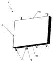
在图1中绘制出根据现有技术的棱柱形存储电池1。该棱柱形存储电池1通常安放在棱柱形电池壳体2中,该电池壳体2带有两个相互平行地布置的大表面3和四个窄侧面4,这些窄侧面以其窄边长定义了电池深度或者说电池厚度。存储电池1的两个电极5从向上指向的侧面4a,即顶面4a突出。A
图2示出存储电池1的带有组合固定装置6的棱柱形电池壳体2,该电池壳体例如以铝制挤压部件的形式得到。在这个实施例中,作为用于固定散热体的装置,棱柱形电池壳体2具有至少一个底侧的固定装置6,即构造在向下指向的、构成电池壳体底部4b的窄侧面4b上的固定装置6,所述窄侧面4b与电池壳体的顶面4a平行地相对置。根据图2中的视图,设置有四个半铆钉7作为固定装置6。FIG. 2 shows the
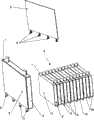
如果相应的装置不应用在该电池壳体上,则如图3所示,电池模块9的电池堆栈扩展出至少一个隔板8,所述隔板允许至少一个固定装置6在电池模块9的底侧突出。图3所示为电池堆栈形式的这种电池模块9,在该电池模块中,棱柱形电池壳体4通过其相互平行地布置的大表面3以相互重叠的堆栈方式布置。另外,在与该棱柱形电池壳体2相邻的存储电池1之间插入隔板8,从而在电池模块2的电池堆栈中,存储电池1和隔板8交替地、互相重叠布置。这里,存储电池1的电池壳体底部4b与隔板8的底面一起形成电池模块底部10,固定装置6从该电池模块底部突出。根据图3中的视图,固定装置6与半铆钉7的轮廓相对应。If the corresponding device is not used on the battery housing, then, as shown in FIG. side prominence. FIG. 3 shows such a
图4示出夹紧的电池模块9。该电池模块9包括多个存储电池1以及插入在存储电池的棱柱形电池壳体之间的隔板8,所述存储电池的棱柱形电池壳体4通过其相互平行地布置的大表面3以相互重叠的堆栈方式布置。棱柱形电池壳体2和隔板8以这种方式形成电池堆栈形式的电池模块9,在所述电池堆栈中,存储电池1的电池壳体2和隔板8交替地、互相重叠地布置。FIG. 4 shows a clamped
电池模块9借助夹紧装置夹紧。根据图4中的视图,该夹紧装置首先包括两个夹紧板11,这些夹紧板各带有三个水平指向的、平行地间隔开的夹紧体11a,这些夹紧体分别位于电池模块1的端面12上,其中,夹紧板11设计成比电池壳体2的大表面3更宽并且在水平方向上于两侧超过电池壳体。在此,夹紧板11的位于电池模块9的相反端面12上的这些夹紧体11a分别通过总共六个夹紧轴13互相连接,这些夹紧轴在两侧(每侧三个夹紧轴)平行于电池模块9的长侧面14延伸。夹紧轴13的两个端部区域15穿过夹紧体11a中的穿孔,其中,两个端部区域15根据图4中的视图构造为外螺纹,其相应于作为夹紧器16的六角形螺母16的内螺纹。通过在两侧平行于电池模块9的长侧面14放置的夹紧轴13的端部区域15与夹紧器16的旋紧,实现了电池模块夹紧的过程,其中根据图4中的视图,在夹紧器16与夹紧体11a之间分别放置垫片17。在电池模块夹紧之后,隔板8力锁合地固定在存储电池1之间,固定装置6因此能够承受电池高度方向上的拉伸力。如果不设置模块夹紧装置,则例如可使用根据图5的带有顶侧卷边18的隔板8。在该可供选择的关于隔板8的变形中,隔板8的突起式板条19形式的固定装置6带有底侧折边20。作为相应的相反支架,如图6所示,隔板8中的交替侧地指向的卷边18位于电池壳体2的顶面4a上。这里,带有顶侧卷边的隔板8充当拉伸方向上的支座以支持摩擦力,或者充当关于未受挤压的电池模块的变型。The
图7所示为用于电池组件的散热体21的结构。根据图7,散热体21能够由带有总管23的宽的多通道平管22组成。此外,该散热体21还有多个穿孔24。在带有穿孔24的位置上要么不存在多通道平管22的通道,要么这些通道通过相应的手段不与总管23接通。对于非常宽的存储电池而言,推荐使用更多窄的多通道平管22,所述平管22由共同的底板25所保持,其简化了装配,但也能够具有热绝缘的性质。FIG. 7 shows the structure of the
另一个用于散热体21的构造形式表现为板形式,正如可从板传热中了解到的一样。然而,这些板不是由两个独具风格的、由板材制成的半壳组成,而最好是独具风格的金属板和平坦的金属板组成。出于密封性原因,两个板最好是互相钎焊或焊接。平坦的板侧面与存储电池的底部有热接触。宽的多通道平管22或者板不排除使用底板25,例如出于强度或热技术的原因。Another embodiment for the cooling
图8表现将夹紧的电池模块和散热体21连接到一起的过程。如此设计散热体21,使得散热媒介的主要流动方向与电池模块9中的存储电池1交叉,或者在电池深度(电池厚度)的方向上定向。如上所述,为了能够有效地导散在存储电池1上出现的损耗热,散热体21具有与模块上的固定装置6(根据图8的半铆钉)的类型相应的穿孔24,使得散热体21能够与所有电池壳体2中的电池壳体底部面4b接触。FIG. 8 shows the process of connecting the clamped battery module and the cooling
将散热体21固定到电池模块9上,或者平面地压紧到电池壳体底部4b上用于无间断地热传导,根据图9a和图9b,通过特别的夹紧元件26来实现,其中图9a示出单个夹紧元件,并且图9b显示了通过第一夹紧元件26将散热体21装配到电池模块9上。根据在图9b中所显示的实施例,夹紧元件26不宽于两个电池深度,并且大约与存储电池1的宽度等长。可供选择地,夹紧元件26也能够被实现得较宽,以便其能够同时固定多个存储电池1或者整个电池模块9,并且朝着散热体21压紧。夹紧元件26的高度和横截面除了取决于材料性质以外,还取决于每个存储电池1或每个隔板8中固定装置6的宽度和数量。夹紧元件26具有与存储电池1/电池模块9上的固定装置相应的穿孔27,所述穿孔侧向地过渡到T型槽28。通过穿孔27,夹紧元件26能够穿过固定装置6平放到散热体21或者其底部25上。通过侧向移动夹紧元件26,固定装置6的顶端能够进入T型槽28中。因为T型槽28的接触面倾斜地(斜面)形成(可供选择地,固定装置6的顶端的接触面,或者这两个面都可以倾斜地形成),夹紧元件26和固定装置6使相应的存储电池1或者电池模块9被彼此相对拉动。如果夹紧元件26到达其最终位置,则电池壳体底部(图9b中未显示,见图8)和散热体21在很大程度上相互挤压,使得它们的表面相互接触并且保证不间断的传热。在另一个未显示的设计方案中,通过滑动元件实现平板形散热体的简单且同时的固定和夹紧,所述滑动元件不可遗失地预装配在平板形散热体的导轨上。所述导轨组合到底板25的底面上,并且在夹紧元件26上设置相应的相对件。The cooling
图10示出使用总共六个夹紧元件26将散热体21装配在电池模块9上。如果这些夹紧元件26由塑料制成并且期望放松在固定装置6与夹紧元件26之间所需平面挤压,则在T型槽28范围中夹紧元件被铺上金属垫片或者弹簧元件。额外地或可供选择地,在T型槽28范围内夹紧元件26具有大量的金属核或插入物。在另一个未显示的设计方案中,夹紧元件26通过T型导轨、燕尾导轨或者类似件与底板25不可遗失地预装配。FIG. 10 shows the mounting of cooling
最后,图11显示了完整装配的、用于混合动力车辆或者电动车辆的电池组件29,其包括电池模块9和散热体21。Finally, FIG. 11 shows a fully assembled
附图标记列表List of reference signs
1 存储电池 14 电池模块9的长侧面1
2 电池壳体 15 (夹紧轴13的)端部区域2
3 大表面 16 夹紧器,螺母3
4 窄侧面 17 垫片4
4a 侧面,顶面 18 (隔板8的)顶侧卷边4a side, top 18 (of partition 8) top side beading
4b 侧面,电池壳体底部 19 突起状板条4b Side, bottom of battery housing 19 Raised slats
5 存储电池的电极 20 (突起状板条的)底侧折边5 Electrodes of storage batteries 20 Bottom side fold (of protruding slats)
6 固定装置 21 散热体6 Fixing
7 半铆钉 22 多通道平管7
8 隔板 23 总管8
9 电池模块 24 (散热体21中的)空隙,穿孔9 battery module 24 (in the cooling body 21) gap, perforation
10 电池模块底部 25 底板10 Bottom of the
11 夹紧板 26 夹紧元件11
11a 夹紧体 27 (夹紧元件26中的)穿孔
12 端面 28 T型槽12 End face 28 T-slot
13 夹紧轴 29 电池组件13 clamping
Claims (10)
Translated fromChineseApplications Claiming Priority (4)
| Application Number | Priority Date | Filing Date | Title |
|---|---|---|---|
| DE102009027465.0 | 2009-07-03 | ||
| DE102009027465 | 2009-07-03 | ||
| DE102010029872ADE102010029872A1 (en) | 2009-07-03 | 2010-06-09 | Battery assembly for hybrid or electric vehicles |
| DE102010029872.7 | 2010-06-09 |
Publications (2)
| Publication Number | Publication Date |
|---|---|
| CN101944643Atrue CN101944643A (en) | 2011-01-12 |
| CN101944643B CN101944643B (en) | 2015-02-18 |
Family
ID=43299295
Family Applications (1)
| Application Number | Title | Priority Date | Filing Date |
|---|---|---|---|
| CN201010224829.1AActiveCN101944643B (en) | 2009-07-03 | 2010-07-05 | Battery unit for hybrid or electric vehicles |
Country Status (3)
| Country | Link |
|---|---|
| US (1) | US8524387B2 (en) |
| CN (1) | CN101944643B (en) |
| DE (1) | DE102010029872A1 (en) |
Cited By (13)
| Publication number | Priority date | Publication date | Assignee | Title |
|---|---|---|---|---|
| CN102437305A (en)* | 2011-12-16 | 2012-05-02 | 淄博国利新电源科技有限公司 | Three-dimensional ventilating battery partition plate |
| CN103178311A (en)* | 2011-12-22 | 2013-06-26 | 三星Sdi株式会社 | Battery module |
| CN103718374A (en)* | 2011-04-15 | 2014-04-09 | 约翰逊控制技术有限责任公司 | Battery system with external thermal management system |
| CN103733375A (en)* | 2011-06-10 | 2014-04-16 | 罗伯特·博世有限公司 | Battery and motor vehicle comprising said battery |
| CN103947004A (en)* | 2011-08-25 | 2014-07-23 | 罗伯特·博世有限公司 | Battery system having temperature control of at least one battery cell, and motor vehicle |
| CN104272498A (en)* | 2012-05-16 | 2015-01-07 | 罗伯特·博世有限公司 | battery pack |
| CN105280980A (en)* | 2014-06-04 | 2016-01-27 | 马勒国际有限公司 | Temperature control device for controlling the temperature of a battery |
| CN108306073A (en)* | 2017-01-12 | 2018-07-20 | 马勒国际有限公司 | Battery temp control device |
| CN108370010A (en)* | 2016-09-19 | 2018-08-03 | 株式会社Lg化学 | Battery pack and vehicle including battery pack |
| CN110556489A (en)* | 2018-05-31 | 2019-12-10 | 本田技研工业株式会社 | battery package |
| CN112736326A (en)* | 2019-10-11 | 2021-04-30 | 罗伯特·博世有限公司 | Battery module |
| CN112787017A (en)* | 2019-11-11 | 2021-05-11 | 奥迪股份公司 | Method for mounting power battery of electric vehicle |
| WO2025095899A1 (en)* | 2023-10-30 | 2025-05-08 | Oyak Renault Otomobi̇l Fabri̇kalari Anoni̇m Şi̇rketi̇ | A modular battery case |
Families Citing this family (41)
| Publication number | Priority date | Publication date | Assignee | Title |
|---|---|---|---|---|
| US7531270B2 (en)* | 2006-10-13 | 2009-05-12 | Enerdel, Inc. | Battery pack with integral cooling and bussing devices |
| CN101855775B (en) | 2007-11-07 | 2014-05-14 | 埃纳德尔公司 | Battery assembly with temperature control device |
| DE102010031462A1 (en)* | 2010-07-16 | 2012-01-19 | Sb Limotive Company Ltd. | Battery cell module, battery and motor vehicle |
| DE102011107075B4 (en)* | 2010-08-30 | 2019-11-28 | Samsung Sdi Co., Ltd. | battery module |
| DE102010046529A1 (en)* | 2010-09-24 | 2012-03-29 | Volkswagen Ag | Frame system for battery cells and battery module |
| WO2012052131A2 (en)* | 2010-10-14 | 2012-04-26 | Magna E-Car Systems Gmbh & Co Og | Rechargeable battery having a bending support and production method therefor |
| KR101890830B1 (en)* | 2010-10-29 | 2018-08-22 | 다나 캐나다 코포레이션 | Heat exchanger and battery unit structure for cooling thermally conductive batteries |
| KR101303426B1 (en)* | 2011-01-12 | 2013-09-05 | 로베르트 보쉬 게엠베하 | Battery module |
| JP2014507760A (en)* | 2011-01-26 | 2014-03-27 | エルジー ケム. エルティーディ. | Cooling member with good assembly efficiency and battery module using the same |
| DE102011003535A1 (en)* | 2011-02-02 | 2012-08-02 | Behr Gmbh & Co. Kg | tensioning devices |
| AT511117B1 (en)* | 2011-03-09 | 2014-11-15 | Avl List Gmbh | ELECTRIC ENERGY STORAGE |
| AT511541A1 (en)* | 2011-05-16 | 2012-12-15 | Avl List Gmbh | RECHARGEABLE BATTERY |
| JP2012248339A (en)* | 2011-05-25 | 2012-12-13 | Sanyo Electric Co Ltd | Power unit for electric power and vehicle with power unit |
| DE102011077331A1 (en)* | 2011-06-10 | 2012-12-13 | Sb Limotive Company Ltd. | Battery module, battery with this battery module and motor vehicle with this battery |
| DE102011077340A1 (en)* | 2011-06-10 | 2012-12-13 | Sb Limotive Company Ltd. | Battery module, battery with this battery module and motor vehicle with this battery |
| DE102011107007A1 (en)* | 2011-07-09 | 2013-01-10 | Volkswagen Aktiengesellschaft | Arrangement of traction battery in motor vehicle, has closed hollow profile which is provided with frames connected with coolant supply |
| DE102011080974B4 (en)* | 2011-08-16 | 2023-06-01 | Robert Bosch Gmbh | battery and motor vehicle |
| DE202012102969U1 (en) | 2011-09-21 | 2012-09-05 | Visteon Global Technologies, Inc. | Battery cooling arrangement |
| US9437903B2 (en)* | 2012-01-31 | 2016-09-06 | Johnson Controls Technology Company | Method for cooling a lithium-ion battery pack |
| US9287536B2 (en) | 2012-08-07 | 2016-03-15 | John E. Waters | Battery module construction |
| DE102012218162B4 (en)* | 2012-10-04 | 2023-12-14 | Bayerische Motorenwerke Aktiengesellschaft | Energy storage arrangement |
| US9450275B2 (en) | 2012-12-28 | 2016-09-20 | Johnson Controls Technology Company | Polymerized lithium ion battery cells and modules with overmolded heat sinks |
| DE102013200774A1 (en) | 2013-01-18 | 2014-07-24 | Robert Bosch Gmbh | Device for controlling temperature of battery module of battery system for e.g. electric vehicle, has chamber formed and filled with coolant such that device expands in region of contact surface with inner pressure rising in chamber |
| JP6114041B2 (en)* | 2013-01-21 | 2017-04-12 | 住友重機械工業株式会社 | Storage module and work machine equipped with storage module |
| US20140356652A1 (en)* | 2013-06-04 | 2014-12-04 | Ford Global Technologies, Llc | Battery thermal management system for electrified vehicle |
| DE102013011692A1 (en)* | 2013-07-12 | 2015-01-29 | Daimler Ag | Energy storage device with a tempering device, method for producing the energy storage device |
| DE102013112732B4 (en)* | 2013-11-19 | 2021-04-29 | Dr. Ing. H.C. F. Porsche Aktiengesellschaft | Motor vehicle battery for the purely electric drive of a motor vehicle |
| JP6172016B2 (en)* | 2014-03-26 | 2017-08-02 | 株式会社デンソー | Battery module and battery pack |
| US9887401B2 (en)* | 2015-08-21 | 2018-02-06 | The Boeing Company | Battery assembly, battery containment apparatus, and related methods of manufacture |
| US10109829B2 (en) | 2015-11-05 | 2018-10-23 | Ford Global Technologies, Llc | Support assembly for traction battery |
| US10476045B2 (en) | 2016-02-22 | 2019-11-12 | Ford Global Technologies, Llc | Extruded battery case |
| DE102016009212A1 (en)* | 2016-08-01 | 2018-02-01 | Audi Ag | Battery module and battery |
| US10446893B2 (en)* | 2017-01-23 | 2019-10-15 | Ford Global Technologies, Llc | Electrified vehicle battery packs with battery attachment features |
| JP7261998B2 (en)* | 2017-07-31 | 2023-04-21 | パナソニックIpマネジメント株式会社 | Battery packs and integrated battery packs |
| US11158890B2 (en) | 2017-08-18 | 2021-10-26 | Hyliion Inc. | Battery pack optimization for thermal management |
| ES2745350B2 (en)* | 2018-08-28 | 2021-11-16 | Torres Martinez M | PRESSURIZED ELECTROCHEMICAL BATTERY AND MANUFACTURING PROCESS OF THE SAME |
| JP7151493B2 (en)* | 2019-01-15 | 2022-10-12 | トヨタ自動車株式会社 | battery device |
| JP7298550B2 (en)* | 2020-06-02 | 2023-06-27 | トヨタ自動車株式会社 | power storage device |
| WO2023014329A1 (en)* | 2021-08-04 | 2023-02-09 | İzmi̇r Yüksek Teknoloji̇ Ensti̇tüsü Rektörlüğü | Thermal management system for a hybrid battery pack |
| CN115602965A (en)* | 2022-10-21 | 2023-01-13 | 中国第一汽车股份有限公司(Cn) | A battery cooling structure, battery assembly, electric vehicle and design method |
| CN116093473B (en)* | 2023-04-10 | 2023-06-23 | 江苏智泰新能源科技有限公司 | Combined lithium ion battery energy storage system |
Citations (4)
| Publication number | Priority date | Publication date | Assignee | Title |
|---|---|---|---|---|
| US5419982A (en)* | 1993-12-06 | 1995-05-30 | Valence Technology, Inc. | Corner tab termination for flat-cell batteries |
| EP1117138A1 (en)* | 2000-01-12 | 2001-07-18 | Matsushita Electric Industrial Co., Ltd. | Modular prismatic battery with cooling structure |
| US20030017384A1 (en)* | 2001-07-19 | 2003-01-23 | Matsushita Electric Industrial Co. | Prismatic battery having cooling structure and battery pack using the same |
| DE102007063176A1 (en)* | 2007-12-20 | 2008-09-11 | Daimler Ag | Battery, particularly for hybrid drive or fuel cell vehicle, has heat conducting plate for tempering battery, which has multiple single cells connected together, in parallel or serially |
Family Cites Families (3)
| Publication number | Priority date | Publication date | Assignee | Title |
|---|---|---|---|---|
| DE102004005393A1 (en)* | 2004-02-04 | 2005-08-25 | Daimlerchrysler Ag | Electrochemical energy storage |
| DE102006010063B4 (en) | 2006-03-04 | 2021-09-02 | Bbp Kunststoffwerk Marbach Baier Gmbh | Cooling device for batteries |
| EP2153487B1 (en) | 2007-04-05 | 2013-06-19 | Behr GmbH & Co. KG | Electrochemical energy storage unit comprising a cooling device |
- 2010
- 2010-06-09DEDE102010029872Apatent/DE102010029872A1/enactivePending
- 2010-07-01USUS12/829,307patent/US8524387B2/ennot_activeExpired - Fee Related
- 2010-07-05CNCN201010224829.1Apatent/CN101944643B/enactiveActive
Patent Citations (4)
| Publication number | Priority date | Publication date | Assignee | Title |
|---|---|---|---|---|
| US5419982A (en)* | 1993-12-06 | 1995-05-30 | Valence Technology, Inc. | Corner tab termination for flat-cell batteries |
| EP1117138A1 (en)* | 2000-01-12 | 2001-07-18 | Matsushita Electric Industrial Co., Ltd. | Modular prismatic battery with cooling structure |
| US20030017384A1 (en)* | 2001-07-19 | 2003-01-23 | Matsushita Electric Industrial Co. | Prismatic battery having cooling structure and battery pack using the same |
| DE102007063176A1 (en)* | 2007-12-20 | 2008-09-11 | Daimler Ag | Battery, particularly for hybrid drive or fuel cell vehicle, has heat conducting plate for tempering battery, which has multiple single cells connected together, in parallel or serially |
Cited By (18)
| Publication number | Priority date | Publication date | Assignee | Title |
|---|---|---|---|---|
| CN103718374B (en)* | 2011-04-15 | 2017-11-03 | 约翰逊控制技术有限责任公司 | Battery system with external thermal management system |
| CN103718374A (en)* | 2011-04-15 | 2014-04-09 | 约翰逊控制技术有限责任公司 | Battery system with external thermal management system |
| CN103733375B (en)* | 2011-06-10 | 2017-05-17 | 罗伯特·博世有限公司 | Battery and motor vehicle comprising said battery |
| CN103733375A (en)* | 2011-06-10 | 2014-04-16 | 罗伯特·博世有限公司 | Battery and motor vehicle comprising said battery |
| CN103947004A (en)* | 2011-08-25 | 2014-07-23 | 罗伯特·博世有限公司 | Battery system having temperature control of at least one battery cell, and motor vehicle |
| CN102437305A (en)* | 2011-12-16 | 2012-05-02 | 淄博国利新电源科技有限公司 | Three-dimensional ventilating battery partition plate |
| CN106935932A (en)* | 2011-12-22 | 2017-07-07 | 三星Sdi株式会社 | Battery module |
| CN103178311A (en)* | 2011-12-22 | 2013-06-26 | 三星Sdi株式会社 | Battery module |
| CN104272498A (en)* | 2012-05-16 | 2015-01-07 | 罗伯特·博世有限公司 | battery pack |
| CN104272498B (en)* | 2012-05-16 | 2019-07-09 | 罗伯特·博世有限公司 | Battery component |
| CN105280980A (en)* | 2014-06-04 | 2016-01-27 | 马勒国际有限公司 | Temperature control device for controlling the temperature of a battery |
| CN108370010A (en)* | 2016-09-19 | 2018-08-03 | 株式会社Lg化学 | Battery pack and vehicle including battery pack |
| CN108306073A (en)* | 2017-01-12 | 2018-07-20 | 马勒国际有限公司 | Battery temp control device |
| CN110556489A (en)* | 2018-05-31 | 2019-12-10 | 本田技研工业株式会社 | battery package |
| CN112736326A (en)* | 2019-10-11 | 2021-04-30 | 罗伯特·博世有限公司 | Battery module |
| CN112787017A (en)* | 2019-11-11 | 2021-05-11 | 奥迪股份公司 | Method for mounting power battery of electric vehicle |
| US11611118B2 (en) | 2019-11-11 | 2023-03-21 | Audi Ag | Method for assembling a traction battery for an electrically operated vehicle |
| WO2025095899A1 (en)* | 2023-10-30 | 2025-05-08 | Oyak Renault Otomobi̇l Fabri̇kalari Anoni̇m Şi̇rketi̇ | A modular battery case |
Also Published As
| Publication number | Publication date |
|---|---|
| CN101944643B (en) | 2015-02-18 |
| US8524387B2 (en) | 2013-09-03 |
| DE102010029872A1 (en) | 2011-01-05 |
| US20110003187A1 (en) | 2011-01-06 |
Similar Documents
| Publication | Publication Date | Title |
|---|---|---|
| CN101944643B (en) | Battery unit for hybrid or electric vehicles | |
| CN103650200B (en) | Electric supply installation | |
| CN104037373B (en) | Series of cells and there is the battery module of this series of cells | |
| CN106785183B (en) | Power battery package and electric automobile | |
| CN102934277B (en) | Device for supplying power, having a cooling assembly | |
| JP6655062B2 (en) | Energy supply module for a voltage supply device provided in a vehicle | |
| US8999548B2 (en) | Liquid-cooled battery module | |
| JP5893159B2 (en) | Batteries and cell blocks for batteries | |
| CN102272975A (en) | Thermally Optimized Automotive Power Supplies | |
| CN106329022A (en) | Motor vehicle battery | |
| JP6019110B2 (en) | Energy storage module comprising a plurality of prismatic storage cells | |
| JP2023501742A (en) | Battery packs and electric vehicles | |
| KR20140078558A (en) | Apparatus for contacting heat exchanger elements with battery modules of motor vehicle | |
| CN214706037U (en) | Thermal pads and battery packs | |
| JP2012204129A (en) | Battery pack | |
| JP2015510230A (en) | Housing for electrical module of battery pack for automobile, and related battery pack | |
| CN111525054A (en) | Battery bracket assembly | |
| KR20110100263A (en) | Heat-stabilized electric battery module | |
| JP2009134901A (en) | Battery system | |
| CN104900822A (en) | Energy storage enclosure | |
| JP2014510381A (en) | Energy storage device with temperature control means | |
| KR20140004830A (en) | Cooling member for battery cell | |
| CN114051673B (en) | Power storage group | |
| KR20150037335A (en) | Battery Module with Cooling Member | |
| CN115336092B (en) | Battery pack and device comprising same |
Legal Events
| Date | Code | Title | Description |
|---|---|---|---|
| C06 | Publication | ||
| PB01 | Publication | ||
| C10 | Entry into substantive examination | ||
| SE01 | Entry into force of request for substantive examination | ||
| ASS | Succession or assignment of patent right | Owner name:HALLA VISTEON CLIMATE CONTROL CORP. Free format text:FORMER OWNER: WESTONE WORLDWIDE TECH. CORP. Effective date:20130922 | |
| C41 | Transfer of patent application or patent right or utility model | ||
| TA01 | Transfer of patent application right | Effective date of registration:20130922 Address after:South Korea Applicant after:Halla Climate Control Corp Address before:American Michigan Applicant before:Visteon Global Tech. Inc | |
| C14 | Grant of patent or utility model | ||
| GR01 | Patent grant | ||
| C56 | Change in the name or address of the patentee | ||
| CP01 | Change in the name or title of a patent holder | Address after:South Korea Patentee after:Hanang System Co., Ltd. Address before:South Korea Patentee before:Halla Climate Control Corp | |
| CP01 | Change in the name or title of a patent holder | ||
| CP01 | Change in the name or title of a patent holder | Address after:Han Guodatianshi Patentee after:HANON SYSTEMS Address before:Han Guodatianshi Patentee before:HANON SYSTEMS |