CN101937232A - Embedded real-time simulation and fault simulation system based on multi-channel data bus - Google Patents
Embedded real-time simulation and fault simulation system based on multi-channel data busDownload PDFInfo
- Publication number
- CN101937232A CN101937232ACN 201010274736CN201010274736ACN101937232ACN 101937232 ACN101937232 ACN 101937232ACN 201010274736CN201010274736CN 201010274736CN 201010274736 ACN201010274736 ACN 201010274736ACN 101937232 ACN101937232 ACN 101937232A
- Authority
- CN
- China
- Prior art keywords
- simulation
- fault
- data
- interrupt
- channel
- Prior art date
- Legal status (The legal status is an assumption and is not a legal conclusion. Google has not performed a legal analysis and makes no representation as to the accuracy of the status listed.)
- Granted
Links
Images


Landscapes
- Management, Administration, Business Operations System, And Electronic Commerce (AREA)
Abstract
Translated fromChineseDescription
Translated fromChinese技术领域technical field
本发明涉及一种基于多路数据总线的嵌入式实时仿真与故障模拟系统,属于航天器冗余系统可靠性测试和验证领域。The invention relates to an embedded real-time simulation and fault simulation system based on a multi-channel data bus, which belongs to the field of reliability testing and verification of spacecraft redundancy systems.
背景技术Background technique
高可靠性是对航天器运行的基本要求,冗余容错技术是保证系统高可靠性的有效设计措施。对于航天器冗余系统,需要有效的测试手段,通过向被测冗余系统注入故障来测试系统的容错能力,验证系统的冗余设计。High reliability is the basic requirement for spacecraft operation, and redundant fault-tolerant technology is an effective design measure to ensure high system reliability. For spacecraft redundant systems, effective testing methods are needed. By injecting faults into the redundant system under test, the fault tolerance of the system can be tested and the redundant design of the system can be verified.
现有的基于故障模拟的航天器冗余系统测试方法主要分为两种。一种方法通过在数据传输通道中串接故障注入装置,实时获取冗余系统数据,然后基于故障仿真方法向原数据中融入故障信息得到故障数据,最后将故障数据输出至容错控制系统实现故障注入。该方法进行测试时需要使用冗余系统中所有真实物理设备,虽然在具有较高的真实性,但却大大降低了测试的灵活性。另一种方法通过实时仿真方式模拟冗余设备数据,然后基于故障仿真方法生成故障数据,最后以与真实设备相同的通信接口实时输出数据。该方法采用实时仿真方式模拟冗余设备,可在缺少真实物理设备的条件下完成测试,既保证了测试的真实性,又提高了测试的灵活性。Existing test methods for spacecraft redundancy systems based on fault simulation are mainly divided into two types. One method obtains redundant system data in real time by connecting a fault injection device in the data transmission channel, then integrates fault information into the original data based on a fault simulation method to obtain fault data, and finally outputs the fault data to a fault-tolerant control system to realize fault injection. This method needs to use all the real physical devices in the redundant system when testing. Although it has high authenticity, it greatly reduces the flexibility of the test. Another method simulates redundant equipment data through real-time simulation, then generates fault data based on the fault simulation method, and finally outputs the data in real time with the same communication interface as the real device. The method uses real-time simulation to simulate redundant equipment, and can complete the test under the condition of lacking real physical equipment, which not only ensures the authenticity of the test, but also improves the flexibility of the test.
对于所述的第二种方法,现有技术通常采用基于设备数学模型的数值计算方式实时模拟设备数据。一方面,由于实时仿真算法严重依赖设备数学模型,因此采用数值计算仿真方式的故障模拟装置通常专用于固定结构的冗余系统测试。若要求对不同冗余系统进行测试,则需要修改底层数值仿真算法来适应被测系统结构及设备类型的变化,通用性较差。另一方面,航天器实际发射任务中积累了大量地面遥测数据,利用这些数据作为实时仿真与故障模拟的数据源将提高仿真数据流的真实性,而采用数值计算仿真方式的故障模拟装置无法实现对遥测数据的利用。For the second method mentioned above, the prior art generally adopts a numerical calculation method based on a mathematical model of equipment to simulate equipment data in real time. On the one hand, since the real-time simulation algorithm relies heavily on the mathematical model of the equipment, the fault simulation device using the numerical calculation simulation method is usually dedicated to the redundant system test of the fixed structure. If it is required to test different redundant systems, it is necessary to modify the underlying numerical simulation algorithm to adapt to changes in the structure of the system under test and the type of equipment, which has poor versatility. On the other hand, a large amount of ground telemetry data has been accumulated in the actual launch mission of the spacecraft. Using these data as a data source for real-time simulation and fault simulation will improve the authenticity of the simulation data flow, but the fault simulation device using numerical calculation simulation method cannot achieve Utilization of Telemetry Data.
另外,基于冗余设计的先进航天器系统结构复杂,设备数量众多(如:32路以上),数据交换频繁(如:1ms传输周期)。对于这类航天器冗余系统进行测试,需要故障模拟装置能够模拟多个设备同时输出数据的过程,这就要求故障模拟装置具备实时控制多路数据总线并行输出故障仿真数据的能力。现有的故障模拟技术通常采用“工业控制计算机+多路同步总线接口卡”的硬件结构实现这一功能。采用这种硬件结构的故障模拟系统存在如下传输不同步问题:①各路同步总线接口卡采用各自时钟独立定时,多路定时器存在时钟偏差,该偏差将随仿真时间增长而变得显著。②工业控制计算机控制各路数据总线启动数据传输的时刻不同步,这将导致各路总线定时起点偏差,该偏差将随总线路数增加而变得显著。In addition, the advanced spacecraft system based on redundant design has a complex structure, a large number of devices (for example: more than 32 channels), and frequent data exchange (for example: 1ms transmission cycle). For the testing of this kind of spacecraft redundancy system, the fault simulator needs to be able to simulate the process of multiple devices outputting data at the same time, which requires the fault simulator to have the ability to control multiple data buses in real time and output fault simulation data in parallel. The existing fault simulation technology usually adopts the hardware structure of "industrial control computer + multi-channel synchronous bus interface card" to realize this function. The fault simulation system using this hardware structure has the following problems of asynchronous transmission: ① Each synchronous bus interface card uses its own independent clock for timing, and the multi-channel timers have clock deviations, which will become significant as the simulation time increases. ② The time when the industrial control computer controls each data bus to start data transmission is not synchronized, which will lead to a deviation in the timing starting point of each bus, and the deviation will become significant as the number of total lines increases.
发明内容Contents of the invention
本发明的目的是为了解决上述问题,提出一种适用于航天器冗余系统测试的基于多路数据总线的嵌入式实时仿真与故障模拟系统。The purpose of the present invention is to solve the above-mentioned problems, and propose an embedded real-time simulation and fault simulation system based on a multi-channel data bus suitable for spacecraft redundancy system testing.
本发明的基于多路数据总线的嵌入式实时仿真与故障模拟系统,包括上位机仿真管理软件与嵌入式实时仿真与故障模拟器。The embedded real-time simulation and fault simulation system based on the multi-channel data bus of the present invention includes a host computer simulation management software and an embedded real-time simulation and fault simulator.
上位机仿真管理软件运行于通用计算机,通过友好的人机界面引导用户针对被测容错控制系统进行仿真配置与故障设置,生成多路冗余设备的故障仿真数据。嵌入式实时仿真与故障模拟器通过多路数据总线实时同步输出故障仿真数据,模拟多路冗余设备发生故障并输出故障数据流的过程。上下位机之间通过以太网进行通信,完成上位机配置信息、故障仿真数据、仿真控制指令的下载与下位机工作状态的上传。已完成文件下载的嵌入式实时仿真与故障模拟器可工作于两种模式下,分别为联机模式和独立模式。联机模式下嵌入式实时仿真与故障模拟器通过以太网与上位机连接,用户通过上位机仿真管理软件发送控制指令遥控仿真进程。独立模式下嵌入式实时仿真与故障模拟器脱机工作,用户通过按键手动控制其仿真进程。The host computer simulation management software runs on a general-purpose computer, guides the user to perform simulation configuration and fault setting for the fault-tolerant control system under test through a friendly man-machine interface, and generates fault simulation data for multi-channel redundant equipment. Embedded real-time simulation and fault simulator output fault simulation data synchronously in real time through multi-channel data bus, and simulate the process of multi-channel redundant equipment failure and output fault data flow. The upper and lower computers communicate through Ethernet to complete the download of configuration information, fault simulation data, and simulation control instructions of the upper computer and upload of the working status of the lower computer. The embedded real-time simulation and fault simulator that has completed the file download can work in two modes, namely online mode and independent mode. In the online mode, the embedded real-time simulation and fault simulator are connected to the host computer through Ethernet, and the user sends control commands to remotely control the simulation process through the host computer simulation management software. In the stand-alone mode, the embedded real-time simulation and fault simulator work offline, and the user manually controls the simulation process by pressing keys.
嵌入式实时仿真与故障模拟器采用读文件方式实时模拟设备故障数据。故障仿真数据由上位机仿真管理软件分两步离线生成:首先由特定数据源按特定插值算法生成仿真数据;然后按照特定故障模拟算法将预设故障注入仿真数据生成故障仿真数据。用于生成仿真数据的数据源既可以是基于数学模型的数值计算结果(数值计算结果指的是根据航天器数学模型进行数值仿真得到的仿真数据,而不是真实数据),也可以是实际航天任务中所记录的真实遥测数据。所提供的插值算法包括:临近点插值、线性插值、三次样条插值以及三次插值。插值计算的目的是利用少量数据得到足量数据,插值计算针对的数据源既可以是数值仿真计算结果,也可以是真实遥测数据,所提供的故障模型及其模拟算法如下:The embedded real-time simulation and fault simulator adopts the method of reading files to simulate equipment fault data in real time. The fault simulation data is generated off-line by the host computer simulation management software in two steps: first, the simulation data is generated by a specific data source according to a specific interpolation algorithm; then, according to a specific fault simulation algorithm, preset faults are injected into the simulation data to generate fault simulation data. The data source used to generate simulation data can be either the numerical calculation results based on the mathematical model (the numerical calculation results refer to the simulation data obtained by numerical simulation based on the spacecraft mathematical model, rather than the real data), or the actual space mission Real telemetry data recorded in . The interpolation algorithms provided include: adjacent point interpolation, linear interpolation, cubic spline interpolation, and cubic interpolation. The purpose of interpolation calculation is to use a small amount of data to obtain sufficient data. The data source for interpolation calculation can be either numerical simulation calculation results or real telemetry data. The provided fault model and its simulation algorithm are as follows:
(1)偏差故障:在原信号上加一恒定或随机信号,该信号幅值不超过原信号幅值;(1) Deviation fault: Add a constant or random signal to the original signal, and the signal amplitude does not exceed the original signal amplitude;
(2)冲击故障:在原信号上加一脉冲信号;(2) Impact failure: add a pulse signal to the original signal;
(3)短路故障:信号接近于零,归一化时用0.1表示;(3) Short-circuit fault: the signal is close to zero, and it is represented by 0.1 when normalized;
(4)开路故障:信号接近最大值,归一化时用0.9表示;(4) Open circuit fault: the signal is close to the maximum value, and it is represented by 0.9 when normalized;
(5)漂移故障:信号以某一速率偏离原信号;(5) Drift fault: the signal deviates from the original signal at a certain rate;
(6)周期性干扰故障:在原信号上叠加某一频率的信号;(6) Periodic interference fault: a signal of a certain frequency is superimposed on the original signal;
上位机仿真管理软件包括:系统配置模块、文件生成模块、通信模块以及工程管理模块。系统配置模块提供清晰完整的人机界面,引导用户对系统结构、仿真参数以及故障信息进行配置。系统配置模块包括系统结构配置子模块、仿真参数配置子模块以及故障信息配置子模块;系统结构配置子模块提供若干设备类型供用户选择,用户从中选择多个设备进行模拟,每个设备类型对应一个由主、备机构成的冗余设备组,针对选定的设备类型,用户配置其冗余方式以及该冗余方式下主、备机所对应的总线端口,冗余方式包括单机、双机以及三机冗余;仿真参数配置子模块引导用户加载用于生成故障仿真数据的数据源,提供插值算法供用户选择,并允许用户配置各个设备的数据传输周期以及总线接口传输参数,从而适应不同数据传输机制的冗余系统的测试要求;故障信息配置子模块提供多种故障类型供用户选择,并允许配置每个故障的发生位置、发生时段、故障类型以及与选定故障类型对应的故障模型参数。文件生成模块利用系统配置模块得到的用户配置信息生成配置文件和多个设备的故障仿真数据文件,其中配置文件用于下位机各路数据总线接口的配置,故障仿真数据文件用于下位机对多个设备故障数据的模拟。文件生成模块还提供配置信息导出功能,将用户配置信息以Word文档形式导出,供用户打印查看。通信模块用于实现与下位机之间的以太网通信,主要负责将文件生成模块生成的配置文件和故障仿真数据文件下载至下位机,在下位机工作于联机模式时还负责发送仿真控制指令。工程管理模块对系统配置过程进行工程化管理,与系统配置模块交互实现用户配置信息的保存和导入操作,方便用户重复配置。The host computer simulation management software includes: system configuration module, file generation module, communication module and project management module. The system configuration module provides a clear and complete man-machine interface to guide users to configure the system structure, simulation parameters and fault information. The system configuration module includes a system structure configuration sub-module, a simulation parameter configuration sub-module and a fault information configuration sub-module; the system structure configuration sub-module provides several device types for users to choose from, and the user selects multiple devices for simulation, and each device type corresponds to a A redundant device group composed of master and backup machines. For the selected device type, the user configures its redundancy mode and the bus ports corresponding to the master and backup machines in this redundancy mode. Redundancy modes include single machine, dual machine and Three-machine redundancy; the simulation parameter configuration sub-module guides users to load the data source used to generate fault simulation data, provides interpolation algorithms for users to choose, and allows users to configure the data transmission cycle of each device and the transmission parameters of the bus interface to adapt to different data The test requirements of the redundant system of the transmission mechanism; the fault information configuration sub-module provides a variety of fault types for users to choose, and allows the configuration of each fault occurrence location, occurrence period, fault type, and fault model parameters corresponding to the selected fault type . The file generation module uses the user configuration information obtained by the system configuration module to generate configuration files and fault simulation data files of multiple devices. Simulation of equipment failure data. The file generation module also provides configuration information export function, which can export user configuration information in the form of Word document for users to print and view. The communication module is used to realize the Ethernet communication with the lower computer. It is mainly responsible for downloading the configuration files and fault simulation data files generated by the file generation module to the lower computer. When the lower computer is working in online mode, it is also responsible for sending simulation control commands. The project management module performs engineering management on the system configuration process, and interacts with the system configuration module to save and import user configuration information, which is convenient for users to configure repeatedly.
嵌入式实时仿真与故障模拟器下位机主要包括:一级CPU、人机接口模块、以太网控制器以及多路数据总线通信模块。一级CPU与所有其它模块连接,控制或协同其它模块运行。人机接口模块包括行列式按键与LCD显示屏,分别用于仿真进程手动控制与系统工作状态实时显示。以太网控制器由一级CPU控制完成与上位机的以太网通信任务。多路数据总线通信模块包含多路FIFO存储器、多路二级CPU、多路总线驱动芯片以及中断管理单元,一路FIFO存储器、一路二级CPU和一路总线驱动芯片组成的一个数据传输信道,每一路负责模拟一个设备的故障数据流,多路数据传输信道由一级CPU定时器统一控制,按各自周期将不同设备的故障仿真数据通过多路总线驱动芯片所提供的总线通信接口同步输出至被测容错控制系统;中断管理单元用于管理多路FIFO存储器“半空”中断,避免多个中断冲突导致中断丢失现象,并按先入先出顺序对中断进行优先级管理,协调一级CPU对多个中断的响应过程;一级CPU连接人机接口模块的行列式按键与LCD控制器,接收用户输入的按键控制指令,通过LCD显示屏输出仿真状态信息;一级CPU连接以太网控制器,接收上位机发送的文件和仿真控制指令并回传下位机状态;一级CPU连接多路数据总线通信模块的多路FIFO存储器和中断管理单元,响应中断管理单元的“半空”中断,将相应故障仿真数据文件中的数据写入FIFO存储器;一级CPU还连接多路数据总线通信模块中多路二级CPU的外部中断管脚,周期性的产生定时器中断信号触发多路二级CPU同步读取并输出故障仿真数据。The lower computer of the embedded real-time simulation and fault simulator mainly includes: a first-level CPU, a human-machine interface module, an Ethernet controller, and a multi-channel data bus communication module. The first-level CPU is connected with all other modules to control or cooperate with other modules to run. The man-machine interface module includes determinant buttons and LCD display, which are used for manual control of the simulation process and real-time display of the system working status. The Ethernet controller is controlled by a first-level CPU to complete the Ethernet communication task with the upper computer. The multi-channel data bus communication module includes multiple channels of FIFO memory, multiple channels of secondary CPU, multiple channels of bus driver chips and interrupt management unit, a data transmission channel composed of one channel of FIFO memory, one channel of secondary CPU and one channel of bus driver chip, each channel It is responsible for simulating the fault data flow of a device. The multi-channel data transmission channel is uniformly controlled by the first-level CPU timer, and the fault simulation data of different devices are synchronously output to the tested device through the bus communication interface provided by the multi-channel bus driver chip according to their respective cycles. Fault-tolerant control system; the interrupt management unit is used to manage the "half-empty" interrupts of the multi-channel FIFO memory, to avoid the phenomenon of interrupt loss caused by multiple interrupt conflicts, and to manage the priority of interrupts in the order of first-in-first-out, and coordinate the first-level CPU to handle multiple interrupts The response process; the first-level CPU is connected to the determinant keys of the man-machine interface module and the LCD controller, receives the key control commands input by the user, and outputs the simulation status information through the LCD display; the first-level CPU is connected to the Ethernet controller, and receives the host computer Send files and simulation control commands and return the status of the lower computer; the first-level CPU connects the multi-channel FIFO memory of the multi-channel data bus communication module and the interrupt management unit, responds to the "half-empty" interrupt of the interrupt management unit, and transfers the corresponding fault simulation data file The data in the FIFO memory is written into the FIFO memory; the primary CPU is also connected to the external interrupt pins of the multiple secondary CPUs in the multi-channel data bus communication module, and periodically generates timer interrupt signals to trigger multiple secondary CPUs to read and output synchronously Fault simulation data.
多路数据总线通信模块中多路FIFO存储器、多路二级CPU、多路总线驱动芯片的各一路组成一路通信子模块,二级CPU收到一级CPU的定时器中断信号后进行中断计数,按其所模拟设备的数据传输周期定时读取FIFO中的数据,并控制与其相连的总线驱动芯片通过总线驱动芯片所支持的总线通信接口将故障仿真数据输出至外部的被测容错控制系统。二级CPU通过对FIFO存储器进行“乒乓”读取实现对一级CPU数据的连续访问,“乒乓”读取过程如下:二级CPU周期性连续读取FIFO存储器;当二级CPU读完FIFO存储器一半存储区时,FIFO存储器将产生“半空”中断;一级CPU向应中断,向FIFO存储器补充新的故障仿真数据。In the multi-channel data bus communication module, the multi-channel FIFO memory, the multi-channel secondary CPU, and the multi-channel bus driver chip each form a communication sub-module. The secondary CPU performs interrupt counting after receiving the timer interrupt signal of the primary CPU. Read the data in the FIFO regularly according to the data transmission cycle of the simulated device, and control the bus driver chip connected to it to output the fault simulation data to the external fault-tolerant control system under test through the bus communication interface supported by the bus driver chip. The second-level CPU realizes continuous access to the first-level CPU data by "ping-pong" reading the FIFO memory. The "ping-pong" reading process is as follows: the second-level CPU periodically and continuously reads the FIFO memory; When the storage area is half, the FIFO memory will generate a "half-empty" interrupt; the first-level CPU should respond to the interrupt, and add new fault simulation data to the FIFO memory.
本发明的优点在于:The advantages of the present invention are:
(1)实时仿真采用实时读取数据文件的方式。与传统的基于设备数学模型的仿真方式相比,本发明所采用的仿真方式既克服了嵌入式测试系统与被测冗余系统对设备数学模型的依赖,提高了测试系统的通用性,又实现了对真实遥测数据的充分利用,提高了实时仿真与故障模拟的真实性;(1) The real-time simulation adopts the method of reading data files in real time. Compared with the traditional simulation method based on the mathematical model of equipment, the simulation method adopted in the present invention not only overcomes the dependence of the embedded test system and the redundant system under test on the mathematical model of the equipment, improves the versatility of the test system, but also realizes Make full use of real telemetry data, improve the authenticity of real-time simulation and fault simulation;
(2)一级CPU为各路二级CPU提供统一定时时钟,二级CPU同步控制各路数据总线按设定周期并行输出数据。与使用多路总线同步接口卡的方式相比,本发明克服了多路总线的时钟偏差问题,提高了同步精度;(2) The first-level CPU provides a unified timing clock for each second-level CPU, and the second-level CPU synchronously controls each data bus to output data in parallel according to the set period. Compared with the method of synchronizing interface cards with multiple buses, the present invention overcomes the clock deviation problem of multiple buses and improves the synchronization accuracy;
(3)仿真管理功能与实时仿真和故障模拟功能分开。上位机软件提供友好人机界面,实现配置的灵活性与易操作性;下位机基于实时操作系统,保证了仿真与故障模拟过程的实时性;(3) The simulation management function is separated from the real-time simulation and fault simulation functions. The upper computer software provides a friendly man-machine interface to achieve configuration flexibility and ease of operation; the lower computer is based on a real-time operating system, which ensures the real-time nature of the simulation and fault simulation process;
(4)采用基于多路数据总线的实时嵌入式系统,与基于工业控制计算机与多路同步总线接口卡的系统相比,其系统成本更低,设备体积重量更小,便携性更好。(4) Compared with the system based on industrial control computer and multi-channel synchronous bus interface card, the real-time embedded system based on multi-channel data bus has lower system cost, smaller equipment volume and weight, and better portability.
附图说明Description of drawings
图1是本发明基于多路数据总线的嵌入式实时仿真与故障模拟系统结构示意图;Fig. 1 is the structural representation of embedded real-time simulation and fault simulation system based on multi-channel data bus of the present invention;
图2是本发明多路RS-485数据通信总线模块组成示意图;Fig. 2 is the composition schematic diagram of multi-channel RS-485 data communication bus module of the present invention;
图3是本发明FIFO存储器中断管理单元工作流程图;Fig. 3 is the work flowchart of FIFO memory interrupt management unit of the present invention;
图4是本发明FIFO存储器的“乒乓”读写流程图;Fig. 4 is " ping-pong " read-write flowchart of FIFO memory of the present invention;
图5是本发明二级CPU定时中断服务子程序流程图;Fig. 5 is the subroutine flow chart of secondary CPU timing interrupt service subroutine of the present invention;
图6是本发明嵌入式实时仿真与故障模拟系统状态转换图;Fig. 6 is a state transition diagram of the embedded real-time simulation and fault simulation system of the present invention;
图中:In the picture:
1000-上位机仿真管理软件 1100-工程管理模块 1200-系统配置模块1000-PC simulation management software 1100-engineering management module 1200-system configuration module
1300-文件生成模块 1400-通信模块 1210-系统结构配置子模块1300-File generation module 1400-Communication module 1210-System structure configuration sub-module
1220-仿真参数配置子模块 1230-故障信息配置子模块1220-Simulation parameter configuration sub-module 1230-Fault information configuration sub-module
2000-嵌入式实时仿真与故障模拟器 2100-一级CPU2000-Embedded real-time simulation and fault simulator 2100-Level 1 CPU
2200-人机接口模块 2300-以太网控制器 2400-多路数据总线通信模块2200-Human-machine interface module 2300-Ethernet controller 2400-Multiple data bus communication module
2210-行列式按键 2220-LCD显示屏 2420-多路FIFO存储器2210-Determinant key 2220-LCD display 2420-Multi-channel FIFO memory
2430-多路二级CPU 2440-多路总线驱动芯片 2410-中断管理单元2430-Multiple secondary CPU 2440-Multiple bus driver chip 2410-Interrupt management unit
2421-FIFO存储器 2431-二级CPU 2441-总线驱动芯片2421-FIFO memory 2431-Secondary CPU 2441-Bus driver chip
2411-中断管理CPU 2412-5-32译码器 2451-RS-485通信子模块2411-Interrupt Management CPU 2412-5-32 Decoder 2451-RS-485 Communication Submodule
3000-以太网 4000-被测容错控制系统3000-Ethernet 4000-The fault-tolerant control system under test
具体实施方式Detailed ways
下面将结合附图和实施例对本发明作进一步的详细说明。The present invention will be further described in detail with reference to the accompanying drawings and embodiments.
本发明是一种基于多路数据总线的嵌入式实时仿真与故障模拟系统,如图1所示,包括上位机仿真管理软件1000和嵌入式实时仿真与故障模拟器2000。The present invention is an embedded real-time simulation and fault simulation system based on multiple data buses, as shown in FIG.
所述数据总线可以是多种类型的串行数据总线,如航天电气系统较为常用RS-485总线、CAN总线、1553B总线等,下面以基于32路RS-485总线的嵌入式实时仿真与故障模拟系统为例本发明的具体实施方式进行说明,所述实施方式同样适用于不同总线种类、不同接口数量的同类系统。The data bus can be various types of serial data buses, such as RS-485 bus, CAN bus, 1553B bus, etc., which are commonly used in aerospace electrical systems. The following uses embedded real-time simulation and fault simulation based on 32 RS-485 buses The system is described as an example of a specific implementation of the present invention, and the implementation is also applicable to similar systems of different types of buses and different numbers of interfaces.
上位机仿真管理软件1000运行于通用计算机,是基于可视化操作系统的图形用户界面软件,上位机仿真管理软件1000包括工程管理模块1100、系统配置模块1200、文件生成模块1300和通信模块1400。工程管理模块1100采用软件工程管理的概念,以工程为单位对每个冗余测试例程进行管理,将所有与工程相关的文件在工程文件夹内部加以组织,支持工程的新建、导入、保存等操作,方便用户对不同仿真测试过程的管理和重复使用。系统配置模块1200提供清晰完整的人机界面,引导用户对系统结构、仿真参数以及故障信息进行配置。系统配置模块1200包括系统结构配置子模块1210、仿真参数配置子模块1220和故障信息配置子模块1230,其中系统结构配置子模块1210提供若干设备类型供用户选择,用户可从中选择多个设备进行模拟。针对选定的设备类型,用户可灵活配置其冗余方式(包括:单机、双机以及三机冗余)以及该冗余方式下主、备机所对应的总线端口,从而适应不同设备构成、不同冗余方式的冗余系统的测试要求。仿真参数配置子模块1220引导用户加载用于生成故障仿真数据的数据源,提供多种插值算法供用户选择,并允许用户在一定范围内任意配置各个设备的数据传输周期以及总线接口传输参数(如:RS-485总线的波特率),从而适应不同数据传输机制的冗余系统的测试要求。故障信息配置子模块1230提供多种故障类型供用户选择,并允许灵活配置每个故障的发生位置、发生时段、故障类型以及与选定故障类型对应的故障模型参数,从而保证故障模拟的真实性和全面性。文件生成模块1300将用户在系统配置模块1200中输入的系统结构参数、数据传输参数统一封装为配置文件,按照指定的数据源、插值算法、传输周期和故障配置信息生成故障仿真数据文件,还可以将系统配置信息生成Word文档供打印输出。通信模块1400通过以太网3000将配置文件和多个设备的故障仿真数据文件下载至下位机,同时负责向下位机发送仿真控制指令。The host computer simulation management software 1000 runs on a general-purpose computer and is a graphical user interface software based on a visual operating system. The host computer simulation management software 1000 includes a project management module 1100, a system configuration module 1200, a file generation module 1300 and a communication module 1400. The project management module 1100 adopts the concept of software project management, manages each redundant test routine in project units, organizes all project-related files in the project folder, and supports project creation, import, and preservation, etc. It is convenient for users to manage and reuse different simulation test processes. The system configuration module 1200 provides a clear and complete man-machine interface to guide users to configure the system structure, simulation parameters and fault information. The system configuration module 1200 includes a system structure configuration sub-module 1210, a simulation parameter configuration sub-module 1220 and a fault information configuration sub-module 1230, wherein the system structure configuration sub-module 1210 provides several equipment types for the user to choose from, and the user can select multiple equipment for simulation . For the selected equipment type, the user can flexibly configure its redundancy mode (including: single machine, dual machine and three machine redundancy) and the bus ports corresponding to the main and standby machines in this redundancy mode, so as to adapt to different equipment configurations, Test requirements for redundant systems with different redundancy methods. The simulation parameter configuration sub-module 1220 guides the user to load the data source used to generate fault simulation data, provides multiple interpolation algorithms for the user to choose, and allows the user to arbitrarily configure the data transmission cycle of each device and the bus interface transmission parameters within a certain range (such as : RS-485 bus baud rate), thus adapting to the test requirements of redundant systems with different data transmission mechanisms. The fault information configuration sub-module 1230 provides a variety of fault types for users to choose, and allows flexible configuration of each fault occurrence location, occurrence period, fault type, and fault model parameters corresponding to the selected fault type, thereby ensuring the authenticity of fault simulation and comprehensiveness. The file generation module 1300 uniformly encapsulates the system structure parameters and data transmission parameters input by the user in the system configuration module 1200 into a configuration file, and generates a fault simulation data file according to the specified data source, interpolation algorithm, transmission cycle and fault configuration information, and can also Generate system configuration information into a Word document for printing. The communication module 1400 downloads configuration files and fault simulation data files of multiple devices to the lower computer through the Ethernet 3000, and is responsible for sending simulation control instructions to the lower computer at the same time.
嵌入式实时仿真与故障模拟器2000硬件包括一级CPU 2100、人机接口模块2200、以太网控制器2300以及多路数据总线通信模块2400。一级CPU 2100与嵌入式实时仿真与故障模拟器2000中所有其它模块连接,控制或协同其它模块运行。人机接口模块2200包括行列式按键2210与LCD显示屏2220,分别用于仿真进程手动控制与系统工作状态实时显示。以太网控制器2300由一级CPU 2100控制完成与上位机的以太网3000通信任务。多路数据总线通信模块2400包含多路FIFO存储器2420、多路二级CPU 2430、多路总线驱动芯片2440和中断管理单元2410,多路FIFO存储器2420、多路二级CPU 2430以及多路总线驱动芯片2440组成的多路数据传输信道,中断管理单元2410用于管理多路FIFO存储器的“半空”中断,多路数据传输信道由一级CPU定时器统一控制,按各自周期将不同设备的故障仿真数据同步输出至被测容错控制系统4000,实现对多路冗余设备故障数据流的实时模拟。The embedded real-time simulation and fault simulator 2000 hardware includes a first-
如图1所示,一级CPU 2100连接人机接口模块2200的行列式按键2210与LCD显示屏2220,接收用户输入的按键控制指令,通过LCD显示屏输出仿真状态信息;连接以太网控制器2300,接收上位机发送的文件和仿真控制指令并回传下位机状态;连接多路数据总线通信模块2400的FIFO存储器中断管理单元2410和FIFO存储器2420,响应中断管理单元的“半空”中断,将相应故障仿真数据文件中的数据写入FIFO存储器;还连接多路数据总线通信模块中所有二级CPU 2430的外部中断管脚,周期性的产生定时器中断信号触发各路数据总线同步输出故障仿真数据。As shown in Figure 1, the first-
一级CPU 2100采用三星公司的ARM9系列微处理器ARM920T。ARM920T具有较大的存储空间,能够一次性存储上位机发送的配置文件与多个故障仿真数据文件;具备一定数量的I/O端口,能够满足32路FIFO存储器2420的寻址要求;内部集成LCD控制器,能够直接控制LCD显示屏2220输出工作状态信息。ARM920T上运行实时嵌入式操作系统VxWorks,具备强实时性和多任务处理能力,能够在向FIFO存储器输出数据的同时与上位机或用户进行交互。The first-
图1中Ⅰ表示仿真控制指令;Ⅱ表示下位机工作状态信息;Ⅲ表示上下位机交互信息;Ⅳ表示多路FIFO存储器“半空”信号;Ⅴ表示多路FIFO存储器写操作使能信号;Ⅵ表示“半空”中断信号;Ⅶ表示半空FIFO存储器所对应的故障仿真数据;Ⅷ表示多路故障仿真数据(并行);Ⅸ表示多路故障仿真数据(串行);Ⅹ表示“配置”中断信号;Ⅺ表示定时器信号。In Figure 1, Ⅰ represents the simulation control command; Ⅱ represents the working status information of the lower computer; Ⅲ represents the interactive information of the upper and lower computers; Ⅳ represents the "half-empty" signal of the multi-channel FIFO memory; "Half-empty" interrupt signal; Ⅶ represents the fault simulation data corresponding to the half-empty FIFO memory; Ⅷ represents the multi-channel fault simulation data (parallel); Ⅸ represents the multi-channel fault simulation data (serial); Ⅹ represents the "configuration" interrupt signal; Ⅺ Indicates a timer signal.
如图2所示,多路数据总线通信模块2400包括一个FIFO存储器中断管理单元2410和32路结构完全相同的RS-485通信子模块2451。FIFO存储器中断管理单元2410对多个FIFO存储器2420的“半空”中断进行捕获,避免多个中断冲突导致的中断丢失现象,并对各个中断进行优先级管理,优先响应先发生的中断。每一路RS-485通信子模块2451连续读取该路RS-485通信子模块2451所模拟设备的故障仿真数据,并通过RS-485总线接口将这些数据实时输出至被测容错控制系统4000。As shown in FIG. 2 , the multi-channel data
如图2所示,FIFO存储器中断管理单元2410由一个中断管理CPU 2411和一个5-32译码器2412组成。中断管理CPU 2411采用Atmel公司的ATmega128单片机,ATmega128具备53路I/O端口,其中的32路(PA0-7、PB0-7、PC0-7、PD0-7)作为输入端口分别连接32路FIFO存储器的“半空”信号输出端,其中5路(PE0-4)作为输出端口将中断源FIFO存储器地址输出至一级CPU和5-32译码器,其中1路(PE5)用作输出端口输出“半空”信号至一级CPU外部中断输入端口,其中1路(PF0)用作输入端口连接一级CPU的“写完”信号输出端。5-32译码器2412可通过级联两片4-16译码器(如:74HC154)实现,其32个输出端分别与32个FIFO存储器的“写入”使能管脚相连,通过片选方式实现32个FIFO存储器对一级CPU输出数据总线的共享。As shown in Figure 2, the FIFO memory interrupt
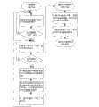
图3所示为FIFO存储器中断管理单元工作流程。FIFO存储器中断管理CPU首先循环扫描与32路FIFO存储器“半空”信号相连的32个I/O端口,直到检测到“半空”信号;然后循环扫描与一级CPU“写完”信号相连的I/O端口,直到检测到“写完”信号,以保证各个FIFO存储器数据输入端所共享的一级CPU数据总线处于空闲状态;中断管理CPU维护一个先入先出的半空FIFO存储器地址队列,从中取出最先产生“半空”信号的FIFO存储器地址,并将该地址输出至一级CPU与5-32译码器,译码器输出端使能相应FIFO存储器的写操作;最后中断管理CPU向一级CPU输出“半空”中断信号。中断管理单元重复上述步骤,处理其它FIFO的“半空”中断。一级CPU响应中断,获取半空FIFO存储器地址,然后将对应设备的故障仿真数据写入FIFO存储器;写完固定周期的数据后一级CPU输出“写完”信号至中断管理CPU。Figure 3 shows the workflow of the FIFO memory interrupt management unit. The FIFO memory interrupt management CPU first cyclically scans the 32 I/O ports connected to the "half empty" signal of the 32-way FIFO memory until the "half empty" signal is detected; then cyclically scans the I/O ports connected to the "write finished" signal of the first-level CPU O port until the "write finished" signal is detected to ensure that the first-level CPU data bus shared by each FIFO memory data input terminal is in an idle state; the interrupt management CPU maintains a first-in-first-out semi-empty FIFO memory address queue, from which it takes out the most First generate the FIFO memory address of the "half-empty" signal, and output the address to the first-level CPU and 5-32 decoder, and the decoder output enables the write operation of the corresponding FIFO memory; finally, interrupt the management CPU to the first-level CPU Output "half empty" interrupt signal. The interrupt management unit repeats the above steps to handle the "half-empty" interrupts of other FIFOs. The first-level CPU responds to the interrupt, obtains the address of the half-empty FIFO memory, and then writes the fault simulation data of the corresponding device into the FIFO memory; after writing the fixed-cycle data, the first-level CPU outputs a "write complete" signal to the interrupt management CPU.
如图2所示,各路RS-485通信子模块结构相同,每路RS-485通信子模块2451包括:FIFO存储器2421、二级CPU 2431以及RS-485总线驱动芯片2441。FIFO存储器2421采用Cypress公司的CY7C4271,所有CY7C4271的数据输入端口连接一级CPU的同一路数据输出端口,各个CY7C4271的数据输出端口分别连接各个二级CPU的数据输入端口,“半空”信号输出端连接中断管理CPU 2411的相应数据输入端,“写入”使能管脚连接中断管理单元中5-32译码器2412的输出管脚。二级CPU 2431采用Atmel公司的ATmega8单片机,每个ATmega8均有两个外部中断输入分别连接至一级CPU的“配置”信号与定时器信号输出端,由一级CPU触发其配置操作与数据实时输出操作。ATmega8的数据输入端口连接相应的FIFO存储器2421的数据输出端口,用于读取FIFO存储器数据;UART异步串口与RS-485总线驱动芯片2441相连,用于串行输出读取的故障仿真数据。总线驱动芯片2441采用Maxim公司的MAX-485,用于将ATmega8单片机UART异步串口输出的TTL电平转换为RS-485电平。As shown in Figure 2, each RS-485 communication sub-module has the same structure, and each RS-485
如图4所示,RS-485通信子模块通过对FIFO存储器的“乒乓”读写方式保证输出数据流的连续性,各个FIFO存储器的“乒乓”读写过程如下:仿真开始前,一级CPU预先向FIFO存储器写入2N周期故障仿真数据,几乎将FIFO存储器写满。图中N为固定整数。N个周期的数据量接近FIFO存储器容量的一半。仿真开始后,二级CPU周期性读取FIFO存储器中的故障仿真数据;当读完FIFO存储器中的一半数据后,FIFO存储器输出“半空”中断信号;FIFO存储器中断管理单元捕获该中断,进行中断处理并最终将中断信号输出至一级CPU;一级CPU响应中断,向FIFO存储器的空半区补充N周期故障仿真数据,几乎将空半区写满。上述“乒乓”读写过程实质上是将整个FIFO存储器动态划分为读、写两个半区,然后通过对两个半区进行同步读写操作,来实现二级CPU对一级CPU数据的连续访问。As shown in Figure 4, the RS-485 communication sub-module ensures the continuity of the output data stream through the "ping-pong" reading and writing method of the FIFO memory. The "ping-pong" reading and writing process of each FIFO memory is as follows: Write 2N cycles of fault simulation data to the FIFO memory in advance, almost filling the FIFO memory. N in the figure is a fixed integer. The amount of data of N cycles is close to half of the FIFO memory capacity. After the simulation starts, the secondary CPU periodically reads the fault simulation data in the FIFO memory; when half of the data in the FIFO memory is read, the FIFO memory outputs a "half-empty" interrupt signal; the FIFO memory interrupt management unit captures the interrupt and interrupts Process and finally output the interrupt signal to the first-level CPU; the first-level CPU responds to the interrupt and supplements the N-period fault simulation data to the empty half of the FIFO memory, almost filling the empty half. The above-mentioned "ping-pong" read and write process is essentially to dynamically divide the entire FIFO memory into two halves for reading and writing, and then perform synchronous read and write operations on the two halves to realize continuous data transfer from the secondary CPU to the primary CPU. access.
各路RS-485通信子模块由一级CPU提供统一定时器,各个二级CPU以软件方式对定时器信号进行分频获得所需要的定时周期,然后按照各自周期读取和输出相应的故障仿真数据,真实模拟多路冗余设备以不同传输周期通过RS-485总线并行输出故障数据的过程。二级CPU定时中断服务子程序流程图如图5所示,二级CPU响应中断后首先进行中断计数,然后对中断计数加以判断:若中断计数所对应的时间达到该路RS-485通信子模块所模拟设备的数据传输周期,则复位中断计数、输出本周期故障仿真数据并预先读取下一周期故障仿真数据;否则不执行上述操作。Each RS-485 communication sub-module is provided with a unified timer by the first-level CPU, and each second-level CPU divides the timer signal by software to obtain the required timing cycle, and then reads and outputs the corresponding fault simulation according to the respective cycle Data, which truly simulates the process of multiple redundant devices outputting fault data in parallel through the RS-485 bus in different transmission cycles. The subroutine flow chart of the secondary CPU timing interrupt service subroutine is shown in Figure 5. After the secondary CPU responds to the interrupt, it first counts the interrupts, and then judges the interrupt count: if the time corresponding to the interrupt count reaches the RS-485 communication submodule of the channel For the data transmission cycle of the simulated device, reset the interrupt count, output the fault simulation data of this cycle, and read the fault simulation data of the next cycle in advance; otherwise, the above operations will not be performed.
如图6所示,嵌入式实时仿真与故障模拟器包含五种工作状态:“复位”、“准备就绪”、“运行”、“暂停”以及“结束”。各状态及其转移过程描述如下:As shown in Figure 6, the embedded real-time simulation and fault simulator contains five working states: "reset", "ready", "running", "pause" and "end". Each state and its transition process are described as follows:
(1)“复位”:该状态下一级CPU未解析文件和分配数据,一级CPU定时器、各路FIFO存储器以及二级CPU均处于复位状态。该状态为系统初始状态,也可通过执行“仿真复位”控制指令转入该状态。(1) "Reset": In this state, the first-level CPU has not parsed the file and allocated data, and the first-level CPU timer, each FIFO memory and the second-level CPU are all in the reset state. This state is the initial state of the system, and it can also be transferred to this state by executing the "simulation reset" control command.
(2)“准备就绪”:该状态下一级CPU已完成配置文件解析与首次数据分配,已完成定时器初始化,FIFO存储器已写入首批数据,各路二级CPU已读取配置信息并完成串口初始化。系统执行“仿真配置”控制指令后转入该状态。(2) "Ready": In this state, the next-level CPU has completed the configuration file analysis and the first data distribution, the timer initialization has been completed, the first batch of data has been written into the FIFO memory, and each secondary CPU has read the configuration information and Complete serial port initialization. The system enters this state after executing the "simulation configuration" control command.
(3)“运行”:该状态下一级CPU定时器运行,一级CPU及时补充各路FIFO存储器中的数据,各路二级CPU实时读取和输出故障仿真数据。系统执行“仿真开始”控制指令后转入该状态。(3) "Run": In this state, the first-level CPU timer runs, the first-level CPU replenishes the data in each FIFO memory in time, and each second-level CPU reads and outputs fault simulation data in real time. The system enters this state after executing the "simulation start" control command.
(4)“暂停”:该状态下一级CPU定时器暂停运行,各路FIFO存储器无存取操作,各路二级CPU处于空闲状态。系统执行“仿真暂停”控制指令后转入该状态。(4) "Pause": In this state, the first-level CPU timer suspends operation, there is no access operation to each FIFO memory, and each second-level CPU is in an idle state. The system enters this state after executing the "simulation pause" control command.
(5)“结束”:该状态下一级CPU定时器停止运行,各路FIFO存储器无存取操作,各路二级CPU处于空闲状态。该状态为系统停止状态,仿真结束后系统自动转入该状态。(5) "End": In this state, the first-level CPU timer stops running, there is no access operation to each FIFO memory, and each second-level CPU is in an idle state. This state is the system stop state, and the system automatically transfers to this state after the simulation ends.
各个仿真控制指令执行情况如下:The execution of each simulation control command is as follows:
(1)“仿真配置”:若当前处于“复位”状态,一级CPU初始化定时器,解析配置文件,为二级CPU分配仿真参数和首批故障仿真数据,并输出中断信号触发二级CPU执行初始化操作。二级MCU初始化完成之后,仿真进入“准备就绪”状态。(1) "Simulation configuration": If it is currently in the "reset" state, the first-level CPU initializes the timer, parses the configuration file, assigns simulation parameters and the first batch of fault simulation data to the second-level CPU, and outputs an interrupt signal to trigger the execution of the second-level CPU Initialize the operation. After the initialization of the secondary MCU is completed, the simulation enters the "ready" state.
(2)“仿真开始”:若当前处于“准备就绪”或“暂停”状态,一级CPU启动定时器,周期性输出定时信号,触发二级CPU通过RS-485串口实时输出故障仿真数据,仿真即进入“运行”状态。(2) "Simulation start": If it is currently in the "ready" or "paused" state, the first-level CPU starts the timer, periodically outputs timing signals, and triggers the second-level CPU to output fault simulation data in real time through the RS-485 serial port. That is, it enters the "running" state.
(3)“仿真暂停”:若当前处于“运行”状态,一级CPU将暂停定时器计数,仿真即进入“暂停”状态。(3) "Simulation Pause": If it is currently in the "running" state, the first-level CPU will suspend the timer counting, and the simulation will enter the "pause" state.
(4)“仿真复位”:若当前未处于“复位”状态,一级CPU将复位定时器以及各路FIFO存储器,仿真即进入“复位”状态。(4) "Simulation reset": If it is not currently in the "reset" state, the first-level CPU will reset the timer and each FIFO memory, and the simulation will enter the "reset" state.
Claims (10)
Translated fromChinesePriority Applications (1)
| Application Number | Priority Date | Filing Date | Title |
|---|---|---|---|
| CN201010274736XACN101937232B (en) | 2010-09-07 | 2010-09-07 | Embedded real-time emulation and fault simulation system based on multiple data buses |
Applications Claiming Priority (1)
| Application Number | Priority Date | Filing Date | Title |
|---|---|---|---|
| CN201010274736XACN101937232B (en) | 2010-09-07 | 2010-09-07 | Embedded real-time emulation and fault simulation system based on multiple data buses |
Publications (2)
| Publication Number | Publication Date |
|---|---|
| CN101937232Atrue CN101937232A (en) | 2011-01-05 |
| CN101937232B CN101937232B (en) | 2012-05-23 |
Family
ID=43390612
Family Applications (1)
| Application Number | Title | Priority Date | Filing Date |
|---|---|---|---|
| CN201010274736XAExpired - Fee RelatedCN101937232B (en) | 2010-09-07 | 2010-09-07 | Embedded real-time emulation and fault simulation system based on multiple data buses |
Country Status (1)
| Country | Link |
|---|---|
| CN (1) | CN101937232B (en) |
Cited By (45)
| Publication number | Priority date | Publication date | Assignee | Title |
|---|---|---|---|---|
| CN102222028A (en)* | 2011-06-28 | 2011-10-19 | 北京电子工程总体研究所 | Signal interface adapter with display device |
| CN103197554A (en)* | 2013-03-18 | 2013-07-10 | 南京航空航天大学 | Spacecraft closed-loop attitude control system based on redundant controller and control method thereof |
| CN103246771A (en)* | 2013-05-10 | 2013-08-14 | 北京航空航天大学 | Fault-tolerant circuit fault effect analytical method based on simulation |
| CN103475547A (en)* | 2013-09-27 | 2013-12-25 | 北京旋极信息技术股份有限公司 | Message transmission method and equipment for GJB5186 test |
| CN103529820A (en)* | 2013-09-26 | 2014-01-22 | 北京航天自动控制研究所 | Fault injection testing system and testing method applied to embedded equipment |
| CN103543714A (en)* | 2013-10-10 | 2014-01-29 | 上海发电设备成套设计研究院 | Module block type control system |
| CN103559112A (en)* | 2013-11-05 | 2014-02-05 | 北京经纬恒润科技有限公司 | Software fault injection method and system |
| CN104391784A (en)* | 2014-08-27 | 2015-03-04 | 北京中电华大电子设计有限责任公司 | Method and device for fault injection attack based on simulation |
| CN104486104A (en)* | 2014-12-03 | 2015-04-01 | 中国航空工业集团公司第六三一研究所 | Fault traffic injection method for airborne network reliability evaluation |
| CN104700686A (en)* | 2013-12-09 | 2015-06-10 | 上海仪电信息网络有限公司 | Real-object simulated maintenance training system for domestic electronic products |
| CN104765709A (en)* | 2015-03-10 | 2015-07-08 | 中国电子科技集团公司第十研究所 | Multi-channel bus data simulation system |
| CN105095129A (en)* | 2015-07-24 | 2015-11-25 | 中国兵器工业集团第二一四研究所苏州研发中心 | Real-time capturing method of multi-channel timer events realized by using hardware |
| CN105550142A (en)* | 2015-12-07 | 2016-05-04 | 中国航空工业集团公司西安航空计算技术研究所 | Data integrity processing method in high and low-speed conversion interface |
| CN105652693A (en)* | 2016-04-15 | 2016-06-08 | 中国工程物理研究院总体工程研究所 | Real-time interpolation method for centrifugal dynamic flight instruction fit for network transmission |
| CN105823909A (en)* | 2015-01-07 | 2016-08-03 | 中国航空综合技术研究所 | Back-driving fault injection interface adapter applicable to electronic products |
| CN103312552B (en)* | 2012-03-12 | 2017-02-08 | 北京泰乐德信息技术有限公司 | Data simulation method, data simulation machine and communication system of data simulation machine |
| CN106444420A (en)* | 2016-08-31 | 2017-02-22 | 中车大连机车研究所有限公司 | Locomotive semi-physical simulation test system and method |
| CN107016206A (en)* | 2017-04-17 | 2017-08-04 | 郑州铁路职业技术学院 | A kind of system and method for emulation for automatic control system |
| CN107102630A (en)* | 2016-02-19 | 2017-08-29 | 同济大学 | A kind of controller board card failure detecting system for magnetic-levitation train |
| CN108572638A (en)* | 2017-03-10 | 2018-09-25 | 雅特生嵌入式计算有限公司 | The stopping of FPGA non-matched data packets for security system |
| CN108665522A (en)* | 2018-05-17 | 2018-10-16 | 北京仿真中心 | A kind of short delay dynamic scene simulation generation system and method for high frame frequency |
| CN108958997A (en)* | 2018-05-23 | 2018-12-07 | 哈尔滨工业大学 | Universal serial bus fault simulation system and analogy method |
| CN109063339A (en)* | 2018-08-03 | 2018-12-21 | 北京航空航天大学 | Digital spacecraft component-level Embedded-system |
| CN109086240A (en)* | 2018-08-28 | 2018-12-25 | 中国科学院长春光学精密机械与物理研究所 | A kind of injected system and method for space loading remote-control data |
| CN109283853A (en)* | 2018-08-28 | 2019-01-29 | 中国科学院长春光学精密机械与物理研究所 | A space payload remote control data transmission system and method |
| CN109614350A (en)* | 2018-10-29 | 2019-04-12 | 中国航空工业集团公司洛阳电光设备研究所 | A kind of interruption system communicated for dual port RAM between processor |
| CN109710551A (en)* | 2018-12-28 | 2019-05-03 | 中国科学院长春光学精密机械与物理研究所 | An injection simulation system based on FMC standard |
| CN109726057A (en)* | 2018-11-19 | 2019-05-07 | 浙江众合科技股份有限公司 | A kind of CPU security system parallel bus failure Real-time and Dynamic Detection method |
| CN109856990A (en)* | 2019-01-17 | 2019-06-07 | 同济大学 | A kind of assemblage on-orbit system of GNSS/INS integrated navigation controller |
| CN110046452A (en)* | 2019-04-25 | 2019-07-23 | 北京世冠金洋科技发展有限公司 | A kind of data/address bus management method, device and electronic equipment |
| CN110286607A (en)* | 2019-07-22 | 2019-09-27 | 中国人民解放军军事科学院国防科技创新研究院 | A kind of spacecraft attitude control jet pipe fault data generation system and method |
| CN110688313A (en)* | 2019-09-26 | 2020-01-14 | 天津津航计算技术研究所 | Fault injection method for software test under VxWorks operating system |
| CN110704315A (en)* | 2019-09-26 | 2020-01-17 | 天津津航计算技术研究所 | Fault injection device for embedded software test |
| CN111294348A (en)* | 2020-01-22 | 2020-06-16 | 北京北方华创微电子装备有限公司 | Data communication method and simulation system of industrial personal computer system and simulation test system |
| CN111443338A (en)* | 2020-05-06 | 2020-07-24 | 中国电子科技集团公司第十四研究所 | An active phased array radar front fault injection device and method |
| CN111625949A (en)* | 2020-05-20 | 2020-09-04 | 北京百度网讯科技有限公司 | Simulation engine system, simulation processing method, device and medium |
| CN111856173A (en)* | 2019-04-26 | 2020-10-30 | 中国北方车辆研究所 | Fault detection device and method for electromagnetic compatibility system |
| CN112000079A (en)* | 2020-08-19 | 2020-11-27 | 北京电子工程总体研究所 | CAN bus node simulation equipment, system and fault simulation method |
| CN112631249A (en)* | 2020-12-15 | 2021-04-09 | 杭州和利时自动化有限公司 | Fault simulation method, device, equipment and computer readable storage medium |
| CN114202990A (en)* | 2021-12-13 | 2022-03-18 | 安胜(天津)飞行模拟系统有限公司 | Fault simulation design method based on eVTOL aircraft |
| CN114239452A (en)* | 2021-12-03 | 2022-03-25 | 海光信息技术股份有限公司 | Design function verification method, system, verification electronic device and storage medium |
| CN114815656A (en)* | 2022-04-11 | 2022-07-29 | 西门子(中国)有限公司 | Stage simulation system and stage simulation method |
| CN115266166A (en)* | 2022-07-20 | 2022-11-01 | 青岛海信日立空调系统有限公司 | An air conditioning test system |
| CN115542931A (en)* | 2021-06-30 | 2022-12-30 | 海鹰航空通用装备有限责任公司 | Flexible configurable digital UAV analog training signal configuration method and application |
| CN118226835A (en)* | 2024-02-05 | 2024-06-21 | 北京蓝天航空科技股份有限公司 | Comprehensive management method and device for flying car simulation experiment |
Citations (4)
| Publication number | Priority date | Publication date | Assignee | Title |
|---|---|---|---|---|
| JP2001117609A (en)* | 1999-10-18 | 2001-04-27 | Accurate Technology Kk | Sequence control simulator |
| US6236332B1 (en)* | 1997-10-22 | 2001-05-22 | Profile Systems, Llc | Control and monitoring system |
| CN101458528A (en)* | 2008-12-23 | 2009-06-17 | 华东理工大学 | On-line fault detection system based on CAN bus |
| CN101782774A (en)* | 2010-01-15 | 2010-07-21 | 许昌开普电器检测研究院 | DC field layer simulation system, digital real-time emulation system and closed loop test system |
- 2010
- 2010-09-07CNCN201010274736XApatent/CN101937232B/ennot_activeExpired - Fee Related
Patent Citations (4)
| Publication number | Priority date | Publication date | Assignee | Title |
|---|---|---|---|---|
| US6236332B1 (en)* | 1997-10-22 | 2001-05-22 | Profile Systems, Llc | Control and monitoring system |
| JP2001117609A (en)* | 1999-10-18 | 2001-04-27 | Accurate Technology Kk | Sequence control simulator |
| CN101458528A (en)* | 2008-12-23 | 2009-06-17 | 华东理工大学 | On-line fault detection system based on CAN bus |
| CN101782774A (en)* | 2010-01-15 | 2010-07-21 | 许昌开普电器检测研究院 | DC field layer simulation system, digital real-time emulation system and closed loop test system |
Non-Patent Citations (1)
| Title |
|---|
| 《宇航学报》 20100831 梁津津 等 基于自适应模糊估计器的卫星容错控制系统 第1970-1975页 1-10 第31卷, 第8期 2* |
Cited By (75)
| Publication number | Priority date | Publication date | Assignee | Title |
|---|---|---|---|---|
| CN102222028A (en)* | 2011-06-28 | 2011-10-19 | 北京电子工程总体研究所 | Signal interface adapter with display device |
| CN103312552B (en)* | 2012-03-12 | 2017-02-08 | 北京泰乐德信息技术有限公司 | Data simulation method, data simulation machine and communication system of data simulation machine |
| CN103197554B (en)* | 2013-03-18 | 2015-07-29 | 南京航空航天大学 | Based on spacecraft closed-loop attitude control system and the control method thereof of redundant manipulator |
| CN103197554A (en)* | 2013-03-18 | 2013-07-10 | 南京航空航天大学 | Spacecraft closed-loop attitude control system based on redundant controller and control method thereof |
| CN103246771A (en)* | 2013-05-10 | 2013-08-14 | 北京航空航天大学 | Fault-tolerant circuit fault effect analytical method based on simulation |
| CN103246771B (en)* | 2013-05-10 | 2017-02-22 | 北京航空航天大学 | Fault-tolerant circuit fault effect analytical method based on simulation |
| CN103529820A (en)* | 2013-09-26 | 2014-01-22 | 北京航天自动控制研究所 | Fault injection testing system and testing method applied to embedded equipment |
| CN103529820B (en)* | 2013-09-26 | 2016-02-10 | 北京航天自动控制研究所 | A kind of direct fault location test macro and method of testing being applicable to embedded device |
| CN103475547A (en)* | 2013-09-27 | 2013-12-25 | 北京旋极信息技术股份有限公司 | Message transmission method and equipment for GJB5186 test |
| CN103543714A (en)* | 2013-10-10 | 2014-01-29 | 上海发电设备成套设计研究院 | Module block type control system |
| CN103543714B (en)* | 2013-10-10 | 2016-08-17 | 上海发电设备成套设计研究院 | A kind of module block type control system |
| CN103559112A (en)* | 2013-11-05 | 2014-02-05 | 北京经纬恒润科技有限公司 | Software fault injection method and system |
| CN103559112B (en)* | 2013-11-05 | 2015-11-25 | 北京经纬恒润科技有限公司 | A kind of software fault injection method and system |
| CN104700686A (en)* | 2013-12-09 | 2015-06-10 | 上海仪电信息网络有限公司 | Real-object simulated maintenance training system for domestic electronic products |
| CN104391784B (en)* | 2014-08-27 | 2017-05-17 | 北京中电华大电子设计有限责任公司 | Method and device for fault injection attack based on simulation |
| CN104391784A (en)* | 2014-08-27 | 2015-03-04 | 北京中电华大电子设计有限责任公司 | Method and device for fault injection attack based on simulation |
| CN104486104A (en)* | 2014-12-03 | 2015-04-01 | 中国航空工业集团公司第六三一研究所 | Fault traffic injection method for airborne network reliability evaluation |
| CN105823909B (en)* | 2015-01-07 | 2018-11-16 | 中国航空综合技术研究所 | A kind of rear-driving type direct fault location interface adapter suitable for electronic product |
| CN105823909A (en)* | 2015-01-07 | 2016-08-03 | 中国航空综合技术研究所 | Back-driving fault injection interface adapter applicable to electronic products |
| CN104765709A (en)* | 2015-03-10 | 2015-07-08 | 中国电子科技集团公司第十研究所 | Multi-channel bus data simulation system |
| CN104765709B (en)* | 2015-03-10 | 2017-12-08 | 中国电子科技集团公司第十研究所 | Multiple bus data simulation system |
| CN105095129B (en)* | 2015-07-24 | 2018-01-30 | 中国兵器工业集团第二一四研究所苏州研发中心 | A kind of hard-wired real-time catching method of multi-path timer event |
| CN105095129A (en)* | 2015-07-24 | 2015-11-25 | 中国兵器工业集团第二一四研究所苏州研发中心 | Real-time capturing method of multi-channel timer events realized by using hardware |
| CN105550142A (en)* | 2015-12-07 | 2016-05-04 | 中国航空工业集团公司西安航空计算技术研究所 | Data integrity processing method in high and low-speed conversion interface |
| CN107102630B (en)* | 2016-02-19 | 2019-12-31 | 同济大学 | Controller card fault detection system for magnetic-levitation train |
| CN107102630A (en)* | 2016-02-19 | 2017-08-29 | 同济大学 | A kind of controller board card failure detecting system for magnetic-levitation train |
| CN105652693A (en)* | 2016-04-15 | 2016-06-08 | 中国工程物理研究院总体工程研究所 | Real-time interpolation method for centrifugal dynamic flight instruction fit for network transmission |
| CN105652693B (en)* | 2016-04-15 | 2018-09-11 | 中国工程物理研究院总体工程研究所 | A kind of centrifugal real-time interpolation method of dynamic flight directive suitable for network transmission |
| CN106444420A (en)* | 2016-08-31 | 2017-02-22 | 中车大连机车研究所有限公司 | Locomotive semi-physical simulation test system and method |
| CN106444420B (en)* | 2016-08-31 | 2019-07-16 | 中车大连机车研究所有限公司 | A kind of locomotive semi-hardware type simulation test system and method |
| CN108572638A (en)* | 2017-03-10 | 2018-09-25 | 雅特生嵌入式计算有限公司 | The stopping of FPGA non-matched data packets for security system |
| CN108572638B (en)* | 2017-03-10 | 2022-02-01 | 雅特生嵌入式计算有限公司 | Stopping of FPGA mismatched data packets for a security system |
| CN107016206A (en)* | 2017-04-17 | 2017-08-04 | 郑州铁路职业技术学院 | A kind of system and method for emulation for automatic control system |
| CN107016206B (en)* | 2017-04-17 | 2020-12-15 | 郑州铁路职业技术学院 | A system and method for simulation of an automatic control system |
| CN108665522B (en)* | 2018-05-17 | 2022-04-19 | 北京仿真中心 | High-frame-frequency short-delay dynamic scene simulation generation system and method |
| CN108665522A (en)* | 2018-05-17 | 2018-10-16 | 北京仿真中心 | A kind of short delay dynamic scene simulation generation system and method for high frame frequency |
| CN108958997A (en)* | 2018-05-23 | 2018-12-07 | 哈尔滨工业大学 | Universal serial bus fault simulation system and analogy method |
| CN108958997B (en)* | 2018-05-23 | 2022-03-04 | 哈尔滨工业大学 | Serial bus fault simulation system and simulation method |
| CN109063339B (en)* | 2018-08-03 | 2023-01-10 | 北京航空航天大学 | Digital spacecraft component-level embedded simulation system |
| CN109063339A (en)* | 2018-08-03 | 2018-12-21 | 北京航空航天大学 | Digital spacecraft component-level Embedded-system |
| CN109283853A (en)* | 2018-08-28 | 2019-01-29 | 中国科学院长春光学精密机械与物理研究所 | A space payload remote control data transmission system and method |
| CN109086240A (en)* | 2018-08-28 | 2018-12-25 | 中国科学院长春光学精密机械与物理研究所 | A kind of injected system and method for space loading remote-control data |
| CN109086240B (en)* | 2018-08-28 | 2020-10-27 | 中国科学院长春光学精密机械与物理研究所 | Injection system and method for space load remote control data |
| CN109614350A (en)* | 2018-10-29 | 2019-04-12 | 中国航空工业集团公司洛阳电光设备研究所 | A kind of interruption system communicated for dual port RAM between processor |
| CN109614350B (en)* | 2018-10-29 | 2022-03-15 | 中国航空工业集团公司洛阳电光设备研究所 | Interrupt system for dual-port RAM communication between processors |
| CN109726057A (en)* | 2018-11-19 | 2019-05-07 | 浙江众合科技股份有限公司 | A kind of CPU security system parallel bus failure Real-time and Dynamic Detection method |
| CN109726057B (en)* | 2018-11-19 | 2022-07-22 | 浙江众合科技股份有限公司 | Real-time dynamic detection method for parallel bus fault of CPU safety system |
| CN109710551B (en)* | 2018-12-28 | 2022-12-06 | 中国科学院长春光学精密机械与物理研究所 | Injection type simulation system based on FMC standard |
| CN109710551A (en)* | 2018-12-28 | 2019-05-03 | 中国科学院长春光学精密机械与物理研究所 | An injection simulation system based on FMC standard |
| CN109856990A (en)* | 2019-01-17 | 2019-06-07 | 同济大学 | A kind of assemblage on-orbit system of GNSS/INS integrated navigation controller |
| CN109856990B (en)* | 2019-01-17 | 2021-09-03 | 同济大学 | In-loop simulation system of GNSS/INS combined navigation controller |
| CN110046452A (en)* | 2019-04-25 | 2019-07-23 | 北京世冠金洋科技发展有限公司 | A kind of data/address bus management method, device and electronic equipment |
| CN111856173A (en)* | 2019-04-26 | 2020-10-30 | 中国北方车辆研究所 | Fault detection device and method for electromagnetic compatibility system |
| CN111856173B (en)* | 2019-04-26 | 2023-07-25 | 中国北方车辆研究所 | Fault detection device and method for electromagnetic compatibility system |
| CN110286607A (en)* | 2019-07-22 | 2019-09-27 | 中国人民解放军军事科学院国防科技创新研究院 | A kind of spacecraft attitude control jet pipe fault data generation system and method |
| CN110286607B (en)* | 2019-07-22 | 2020-04-03 | 中国人民解放军军事科学院国防科技创新研究院 | Spacecraft attitude control spray pipe fault data generation system and method |
| CN110688313A (en)* | 2019-09-26 | 2020-01-14 | 天津津航计算技术研究所 | Fault injection method for software test under VxWorks operating system |
| CN110688313B (en)* | 2019-09-26 | 2022-11-18 | 天津津航计算技术研究所 | Fault injection method for software testing under VxWorks operating system |
| CN110704315A (en)* | 2019-09-26 | 2020-01-17 | 天津津航计算技术研究所 | Fault injection device for embedded software test |
| CN110704315B (en)* | 2019-09-26 | 2022-10-25 | 天津津航计算技术研究所 | Fault injection device for embedded software test |
| CN111294348A (en)* | 2020-01-22 | 2020-06-16 | 北京北方华创微电子装备有限公司 | Data communication method and simulation system of industrial personal computer system and simulation test system |
| CN111294348B (en)* | 2020-01-22 | 2022-06-17 | 北京北方华创微电子装备有限公司 | Data communication method and simulation system of industrial personal computer system and simulation test system |
| CN111443338A (en)* | 2020-05-06 | 2020-07-24 | 中国电子科技集团公司第十四研究所 | An active phased array radar front fault injection device and method |
| CN111625949B (en)* | 2020-05-20 | 2023-09-29 | 北京百度网讯科技有限公司 | Simulation engine system, simulation processing method, device and medium |
| CN111625949A (en)* | 2020-05-20 | 2020-09-04 | 北京百度网讯科技有限公司 | Simulation engine system, simulation processing method, device and medium |
| CN112000079B (en)* | 2020-08-19 | 2021-12-07 | 北京电子工程总体研究所 | CAN bus node simulation equipment, system and fault simulation method |
| CN112000079A (en)* | 2020-08-19 | 2020-11-27 | 北京电子工程总体研究所 | CAN bus node simulation equipment, system and fault simulation method |
| CN112631249A (en)* | 2020-12-15 | 2021-04-09 | 杭州和利时自动化有限公司 | Fault simulation method, device, equipment and computer readable storage medium |
| CN115542931A (en)* | 2021-06-30 | 2022-12-30 | 海鹰航空通用装备有限责任公司 | Flexible configurable digital UAV analog training signal configuration method and application |
| CN114239452A (en)* | 2021-12-03 | 2022-03-25 | 海光信息技术股份有限公司 | Design function verification method, system, verification electronic device and storage medium |
| CN114202990A (en)* | 2021-12-13 | 2022-03-18 | 安胜(天津)飞行模拟系统有限公司 | Fault simulation design method based on eVTOL aircraft |
| CN114202990B (en)* | 2021-12-13 | 2023-12-29 | 安胜(天津)飞行模拟系统有限公司 | eVTOL aircraft-based fault simulation design method |
| CN114815656A (en)* | 2022-04-11 | 2022-07-29 | 西门子(中国)有限公司 | Stage simulation system and stage simulation method |
| CN115266166A (en)* | 2022-07-20 | 2022-11-01 | 青岛海信日立空调系统有限公司 | An air conditioning test system |
| CN118226835A (en)* | 2024-02-05 | 2024-06-21 | 北京蓝天航空科技股份有限公司 | Comprehensive management method and device for flying car simulation experiment |
Also Published As
| Publication number | Publication date |
|---|---|
| CN101937232B (en) | 2012-05-23 |
Similar Documents
| Publication | Publication Date | Title |
|---|---|---|
| CN101937232B (en) | Embedded real-time emulation and fault simulation system based on multiple data buses | |
| CN201886122U (en) | PXI (PCI extension for instrumentation) bus-based digital testing module | |
| CN102360329B (en) | Bus monitoring and debugging control device and methods for monitoring and debugging bus | |
| CN204667101U (en) | A kind of frequency converter controller | |
| WO2016090908A1 (en) | Memory simulation testing board system and testing method for embedded application of intelligent electric meter | |
| CN109194491A (en) | A kind of password evaluation and test pilot system and password evaluate and test test method | |
| CN105357070A (en) | FPGA-based ARINC818 bus analysis and test apparatus | |
| CN112131741B (en) | Real-time dual-kernel single-machine semi-physical simulation architecture and simulation method | |
| CN103984240A (en) | Distributed real-time simulation method based on reflective memory network | |
| CN110838961B (en) | General aviation bus message scheduling system | |
| CN101706762A (en) | Intelligent type signal transfer system | |
| CN103186103A (en) | Satellite-borne equipment simulator and whole satellite simulation system | |
| CN109063339B (en) | Digital spacecraft component-level embedded simulation system | |
| WO2016184170A1 (en) | Smi interface device debugging apparatus and method, and storage medium | |
| CN100422953C (en) | On-line debugging method for SoC system using HDL to expand serial port | |
| CN113438008B (en) | Multi-machine time scale simulation method suitable for attitude and orbit control system multi-machine fault-tolerant architecture | |
| CN114089649A (en) | Automatic test tool system and method | |
| CN110032115B (en) | Internet of things control system and method utilizing near field connection for real-time interaction | |
| CN100555261C (en) | IEEE 1394 communication interface systems of motion controller | |
| CN104867520A (en) | Intelligent data storage unit of exciting magnet apparatus based on ferroelectric random access memory and working method therefor | |
| CN207359076U (en) | A kind of robot control system and robot | |
| CN102722975A (en) | Method and system for reading data of electricity meter based on PROFIBUS | |
| CN107632950A (en) | Processor chips emulator | |
| CN101739338A (en) | Device and method for tracking processor address data | |
| CN204667885U (en) | Based on the excitation unit intelligent data repository unit of ferroelectric memory |
Legal Events
| Date | Code | Title | Description |
|---|---|---|---|
| C06 | Publication | ||
| PB01 | Publication | ||
| C10 | Entry into substantive examination | ||
| SE01 | Entry into force of request for substantive examination | ||
| C14 | Grant of patent or utility model | ||
| GR01 | Patent grant | ||
| CF01 | Termination of patent right due to non-payment of annual fee | ||
| CF01 | Termination of patent right due to non-payment of annual fee | Granted publication date:20120523 Termination date:20170907 |